

Page 1
TR21-WS, TR23-WS, TR21-WK,
TR23-WK, WRECVR
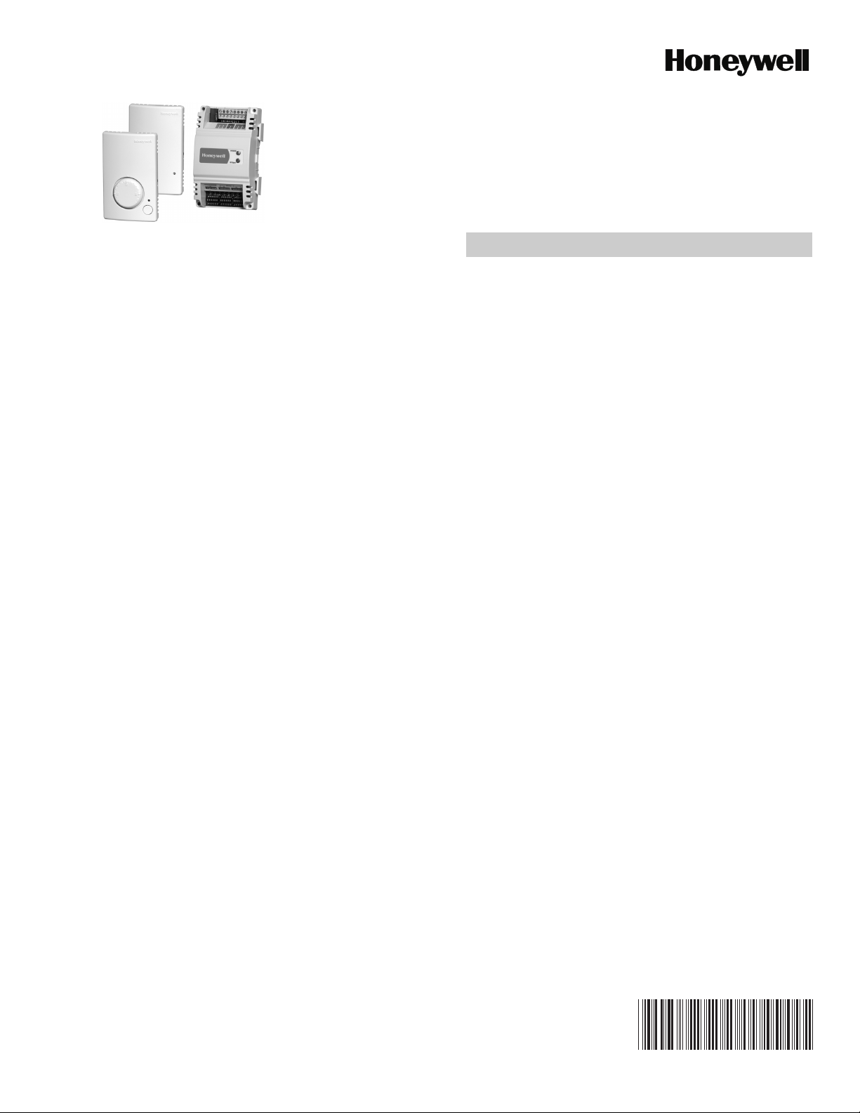
The WRECVR receiver and TR21-WS, TR23-WS, TR21-WK,
and TR23-WK are a family of wireless wall modules and
receiver for use with:
— Spyder Unitary Controllers: PUL, PVL, etc.
— Excel 10 W7750, W7751, W7752, and W7753
controllers
— T7350, T7351, and TB8575 low-voltage SuitePRO™
thermostats
— Will not work with TB7220, TB8220 or TB line voltage
thermostats, XL15s, W7762, W7763 or certain other
XL controllers,
— Will work with WEBs-AX™ I/O Module products if
using a separate transformer
— Compatibility with various other non-Honeywell con-
trollers that accept 10K type2 NTC temperature inputs
SPECIFICATIONS
Models:
TR21-WK: Kit (TR21 and WRECVR bound at factory)
TR23-WK: Kit (TR23 and WRECVR bound at factory)
Replacements:
TR21-WS: Wireless Temperature sensor
TR23-WS: WirelessTemperature sensor, with Setpoint Knobs
(°F, °C, and Relative [warmer to cooler]), O/R Button, and
LED
WRECVR: Receiver
Environmental Ratings:
• Wall Module Operating Temperature: 45° to 99°F (7° to
37°C).
• Receiver Operating Temperature: -40° to 150°F (-40° to
65.5°C).
• Storage Temperature: -40° to 150°F (-40° to 65.5°C).
• Operating Humidity: 5% to 95% RH (non-condensing)
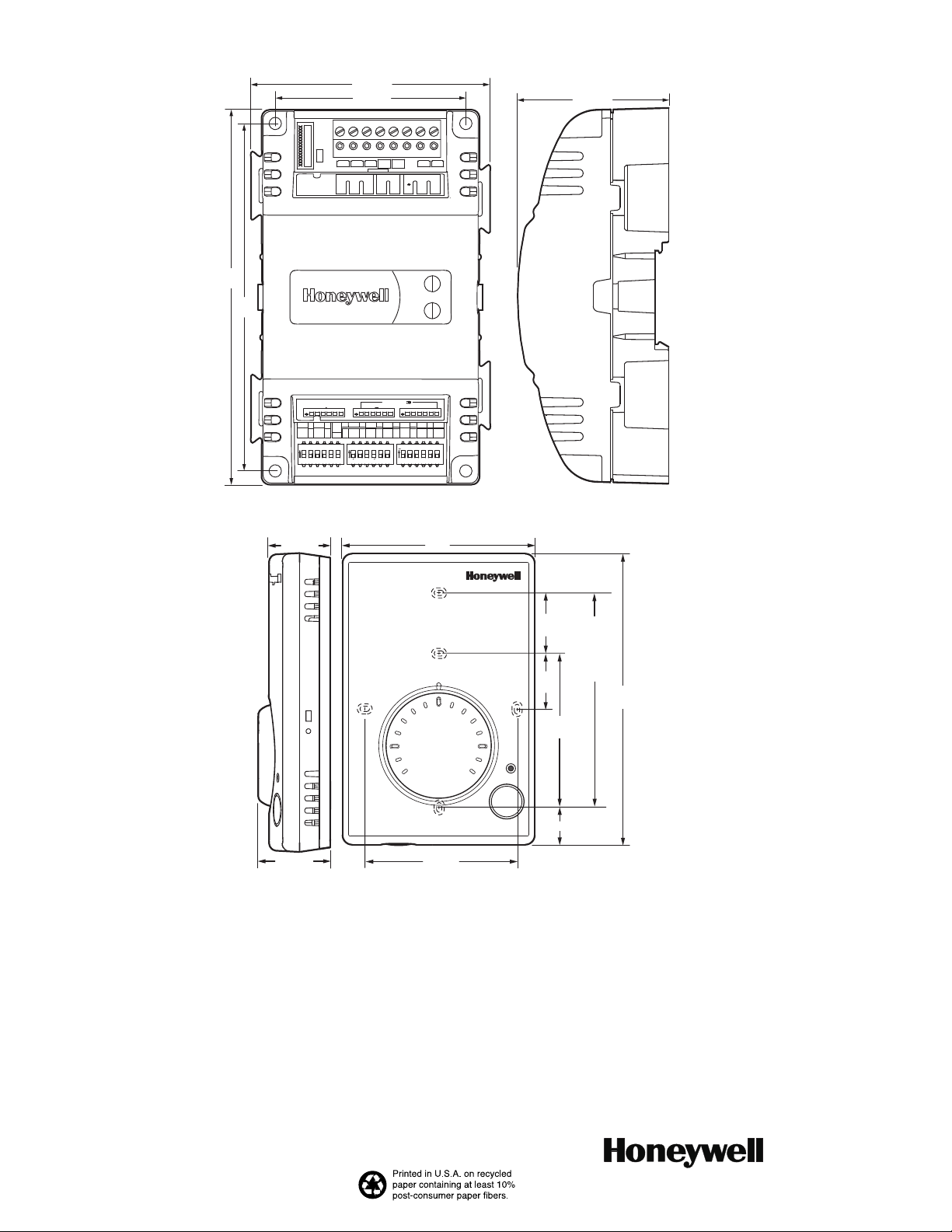
Dimensions: See Fig. 1 and 2.
Accuracy: +/- 1ºF (+/- 0.5ºC) across 12ºC to 30ºC
Setpoint Range for TR23: 56° to 84°F (13° to 29°C)
Accessories: 50007298-001 (pack of 12) medium, cover
plate; 6-7/8 x 5 in. (175 x 127 mm).
Power:
Receiver Voltage: 20 – 30VAC/DC, 50/60Hz; 24VAC typical
Housing:
Wall Module: UL94-HB, Receiver: UL94-5VA
Radio Frequency 2.4 GHz (IEEE Std 802.15.4-2003
compliant)
• Open Range: 3000 feet
• Typical Range: 100 feet
• Output power: 16dBm
• Receiver power consumption: <1.5VA @ 24VAC
• Approximate battery life under normal operating
conditions:
• 5 years with two AA Alkaline batteries (included)
• 7.5 years with two AA Lithium Batteries
Transmission interval: 30 seconds
Pressing override button or signal strength button will force an
immediate transmission.
SPECIFICATION DATA
FEATURES
• Wall module to Receiver (point to point) wireless kits
can replace any standard wired sensor
• Wireless Kits (wall module and receiver) are pre-bound
at the factory for quick installation
• Signal Strength LED built into the wall module
• Low battery indication
• Optional dip switches available to bind any wall
module to any receiver
• Approximate 5 year battery life with AA Alkaline
(included), 7.5 year with Lithium
• Locking screw discourages tampering and battery
theft.
Approvals:
This device complies with Part 15 of the FCC rules. Operation
is subject to the following two conditions:
1) this device may not cause harmful interference, and
2) this device must accept any interference received,
including interference that may cause undesired operation.
General Rules for Installing Wireless Wall Modules
Communication between the wall module and receiver can be
influenced by a number of factors. Type and thickness of
building materials and the way in which they are oriented in
relation to the wall module and receiver will affect
communication.
Do not place either the wall module or receiver inside metal
cabinets or enclosures.Try to orient the wall module and
receiver so that if they are separated by a wall(s), the direction
of signal travel is as perpendicular to the wall(s) as possible.
This reduces the effective wall thickness.
When mounting the receiver on a metal duct, stronger
communication is possible if the wall module is on the same
side of the duct so the signal doesn’t need to travel through
the metal duct.
Reduce as much as possible the amount of metal (ducts, file
cabinets, etc.) between the sensor and the wall module.
Standard drywall (gypsum board) does not greatly affect
signal strength.
63-1332-02
Page 2
TR21-WS, TR23-WS, TR21-WK, TR23-WK, WRECVR
3-13/64 (81)
2-25/32 (71)
8
6
7
TEMP
SETPT
2-13/64 (56)
3
4
OVERRIDE
1
2
24VAC
EGND
COM
5
LOW BAT
5-1/2
(140)
5-3/32
(129)
POWER
RFSignal
CONTROLLER SELECTION
S1
ON
ON ON
1 2 3 4 5 6
ON
1 2 3 4 5 6 1 2 3 4 5 61 2 3 4 5 6
DEVICE
S2 S3
ON
ON
1 2 3 4 5 61 2 3 4 5 6
Fig. 1. Receiver dimensions in in. (mm).
63/64 (25)
3 (77)
70
60
80
7/8
(22)
7/8
(22)
2-3/8
(60)
STANDARD
UTILITY
CONDUIT
BOX (2 X 4)
MOUNTING
HOLES
4-11/16
(119)
M29049
1-5/32 (29)
2-3/8 (60)
Fig. 2. Wall Module subbase dimensions in in. (mm) (TR23 shown)
Automation and Control Solutions
Honeywell International Inc. Honeywell Limited-Honeywell Limitée
1985 Douglas Drive North 35 Dynamic Drive
Golden Valley, MN 55422 Toronto, Ontario M1V 4Z9
customer.honeywell.com
® U.S. Registered Trademark
© 2009 Honeywell International Inc.
63-1332—02 E.K. Rev. 05-09
9/16 (14)
M29050
 Loading...