

AAAA
AAAA
TTTT
TTTT
DDDD
DDDD
oooo
oooo
EEEE
EEEE
uuuu
uuuu
MMMM
MMMM
cccc
cccc
hhhh
hhhh
CCCC
CCCC
CCCC
CCCC
OOOO
OOOO
eeee
eeee
nnnn
nnnn
6666
2222
7777
2222
2222
KKKK
KKKK
SSSS
eeee
eeee
SSSS
yyyy
yyyy
6666
2222
7777
tttt
eeee
rrrr
tttt
eeee
rrrr
User Guide
eeee
eeee
pppp
pppp
rrrr
rrrr
aaaa
aaaa
iiii
eeee
ssss
eeee
dddd
dddd
ssss
ssss
ssss
iiii
800-04705V1 2/10 Rev. A

Table of Contents ( Cont'd)
ABOUT THE TOUCHCENTER.........................................................................5
Introduction...............................................................................................5
The TouchCenter Interface........................................................................ 6
Navigating through the TouchCenter
About Your Home Screen
Customizable Home Screen
Memory C ar d In sertion
Slide Show Application
TouchCenter "Arming" Screen
System Troubles
SYSTEM OVERVIEW ....................................................................................11
Introduction to Your System.....................................................................11
Burglary Protection
Partitions
Zones
............................................................................................... 11
Entry/Exit Delays
Alarms
.............................................................................................. 12
Memory of Alarm
Fire Protection
Carbon Monoxide Protection
User Codes
Extended Functionality
LED Operation
Safe Mode
SECURITY..................................................................................................... 14
Introduction to Security System Operation................................................ 14
............................................................................... 10
.......................................................................................... 11
.............................................................................. 11
.............................................................................. 12
.................................................................................. 12
...................................................................................... 13
.................................................................................. 13
........................................................................................ 13
................................................................... 6
........................................................................ 7
........................................................................ 7
........................................................................... 11
...................................................................... 13
................................................... 6
................................................................ 6
............................................................. 9
............................................................. 12
2

Table of Contents ( Cont'd)
How to Arm the System
How to A rm Mu ltip le Pa rtitions
How to Display Faults
How to Bypass Zones
How to Remove Bypassed Zones
How to Hide a Control Panel Message
How to Disarm the System
How to Check the Status of Other Partitions
Fire Alarm Operation
In Case of Fire Alarm
Silencing and Clearing a Fire Alarm
In Case of Carbon Monoxide Alarm
Silencing and Clearing a Carbon Monoxide Alarm
Advanced System Features
More Choices.......................................................................................... 28
How to Clear a Control Panel Message
Console Emulation Mode
How to Enter Console Emulation Mode
How to View the Event Log
How to Send Emergency Messages......................................................... 32
VOICE MESSAGES....................................................................................... 33
Introduction to Recording and Retrieving Messages..................................33
Recording a Voice Message
Retrieving and Deleting a Voice Message
SETUP .......................................................................................................... 35
Setup...................................................................................................... 35
How to Access Setup
Adjust the Brightness
Adjust the Volume
Disp & Audio Setup................................................................................. 37
.................................................................... 14
........................................................... 15
....................................................................... 17
....................................................................... 18
...................................................... 20
.............................................. 22
................................................................ 22
...................................... 24
......................................................................... 26
........................................................................ 26
................................................... 26
................................................... 27
.............................. 27
.............................................................. 28
............................................. 28
.................................................................. 29
............................................. 29
............................................................... 30
.............................................................. 33
.......................................... 34
........................................................................ 35
........................................................................ 36
............................................................................. 36
3

Table of Contents ( Cont'd)
Operating Modes
Language Selection
Backlight Off Activation Time
Homepage After Time
Auto Slide Show After Time
Clean Screen
Home Setup Button Layout
Routine Care
Reset Home Setup Button Layout
Slide Show Setup....................................................................................45
User Setup..............................................................................................47
Authority Levels
How to Add a User
How to Delete a User
How to Edit a User
Safe Mode
Time/Date Setup
Setting Daylight Savings Time
Setting Current Time and Date
GLOSSARY...................................................................................................61
.............................................................................. 37
.......................................................................... 38
....................................................................... 40
.................................................................................... 42
.................................................................................... 44
................................................................................ 47
............................................................................ 48
........................................................................ 51
............................................................................ 52
........................................................................................ 53
............................................................................... 54
............................................................. 39
............................................................... 41
............................................................... 43
..................................................... 44
........................................................... 55
.......................................................... 57
4

About the TouchCenter
Introduction
Congratulations on your ownership of a Honeywell Security System.
You've made a wise decision in choosing it, for it represents the latest
in security protection technology today.
This security system offers you burglary protection and may provide
fire, carbon monoxide and emergency protection. To realize the full
potential of the system, it is important that you feel comfortable
operating it.
Your system may consist of one or more of the following TouchCenter
Keypads:
• 6272CSV (Color display and Voice feature with silver / black
housing)
• 6272CBV (Color display and Voice feature with black housing)
• 6272CV (Color display and Voice feature with white housing)
• One or more other keypads for system control
• Various sensors for perimeter and interior burglary protection,
plus a selected number of strategically placed smoke, carbon
monoxide or combustion detectors
• Lighting/switching devices.
Note: The 6272 Series devices are certified SIA-compliant devi c es that
meet SIA specific ations for False Alarm Reduction.
The system uses microcomputer technology to monitor all zones, and
provides appropriate information for display on the TouchCenter
and/or other keypads used with the system. Your system may also
have been programmed to automatically transmit alarm or status
messages over the phone lines to a central alarm monitoring station.
The home lighting feat ur e has not been evaluated by UL.
U
L
5

About the TouchCenter (cont'd)
The TouchCenter In ter face
The TouchCenter is an intuitive, graphical interface that combines
security and optionally, home lighting control. With clear, simple
controls on a touch-screen interface, the entire family will find the
TouchCenter both easy to learn and easy to use.
As a security and home-automation interface, the TouchCenter may
be used for:
• Quick and easy security system operation
• Message storage and retrieval
• Home lighting control
Navigating through the TouchCenter
Navigation through the TouchCenter typically begins from the
"Home" screen. This is the TouchCenter’s main default screen
(starting screen) and is the first screen you will see when the
TouchCenter is powered up and initialized. It is from this screen that
you will select from the main menu. Once you have made your
selection, you will navigate through various sub-menus by touching
graphical buttons or icons to perform the function you desire.
About Your Home Screen
Your "Home" screen is the gateway to your TouchCenter Keypad.
From this screen you can:
• control your security system, and optionally,
• control your message center, and
• control the premises lighting.
Your "Home" screen is displayed most of the time and is
customizable. There is also an additional Slide Show feature which
the user can utilize.
Customizable Home Screen
The 6272 offers a Customizable Home Screen that allows the user to
display personal photos via the external MMC/SD card.
It is recommended that you use the MMC/SD card supplied with the
keypad.
NOTE: In everyday handling, memory cards can become susceptible
to malfunction and/or failure due to electrostatic discharges and the
information on the card may be lost. In some extreme cases, the
keypad may need to be reset. Honeywell is not responsible for any
loss of personal information (files, messages, photos, etc.)
6
About the TouchCenter (Cont'd)
Tips for proper memory card handling:
• Avoid touching the contacts on the card
• Quit the slide show application before removing the memory card
• When removing the memory card from external devices
(PC/Camera) make sure the card is removed properly.
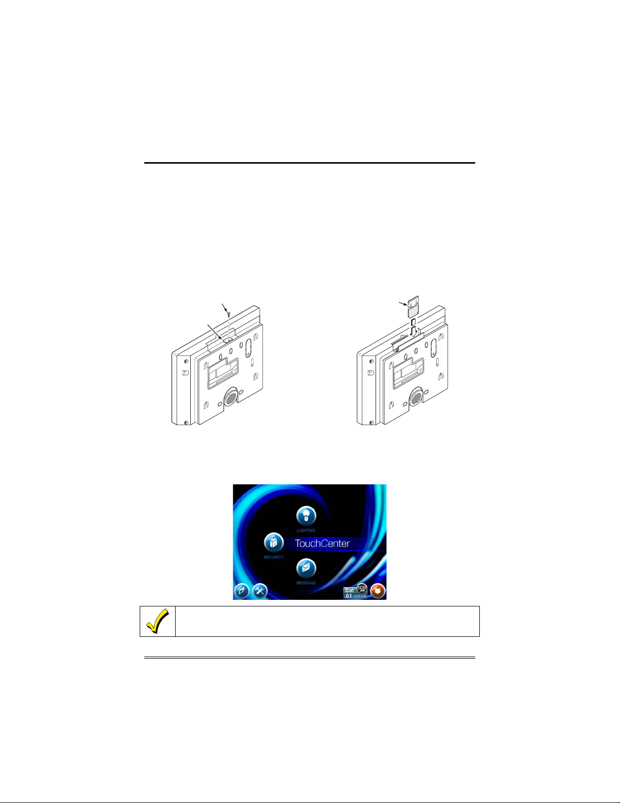
Memory Card Insertion
1. If locking tab is installed and pr ev enting access to the memory
card, remove the screw and the l oc ki ng tab.
2. Lift up and insert memory card, as shown.
SCREW
INSERT CARD
LOCKING TAB
1. REMOVE SCREW AND LOCKING TAB.
2. INSERT MEMORY CARD
6272-007-V0
Slide Show Application
The 6272 offers a Slide Show Application that can be set-up via the
external MMC/SD card. This allows the user to take their personal
photos and display them in a slide show format.
The background and buttons shown on the “Home” screen in this manual are for
example only. Your s yst em ins t aller may hav e ch an ged the actu al backgrou nd
and buttons s h ow n on y our “ Home” scr een.
7
About the TouchCenter (cont'd)
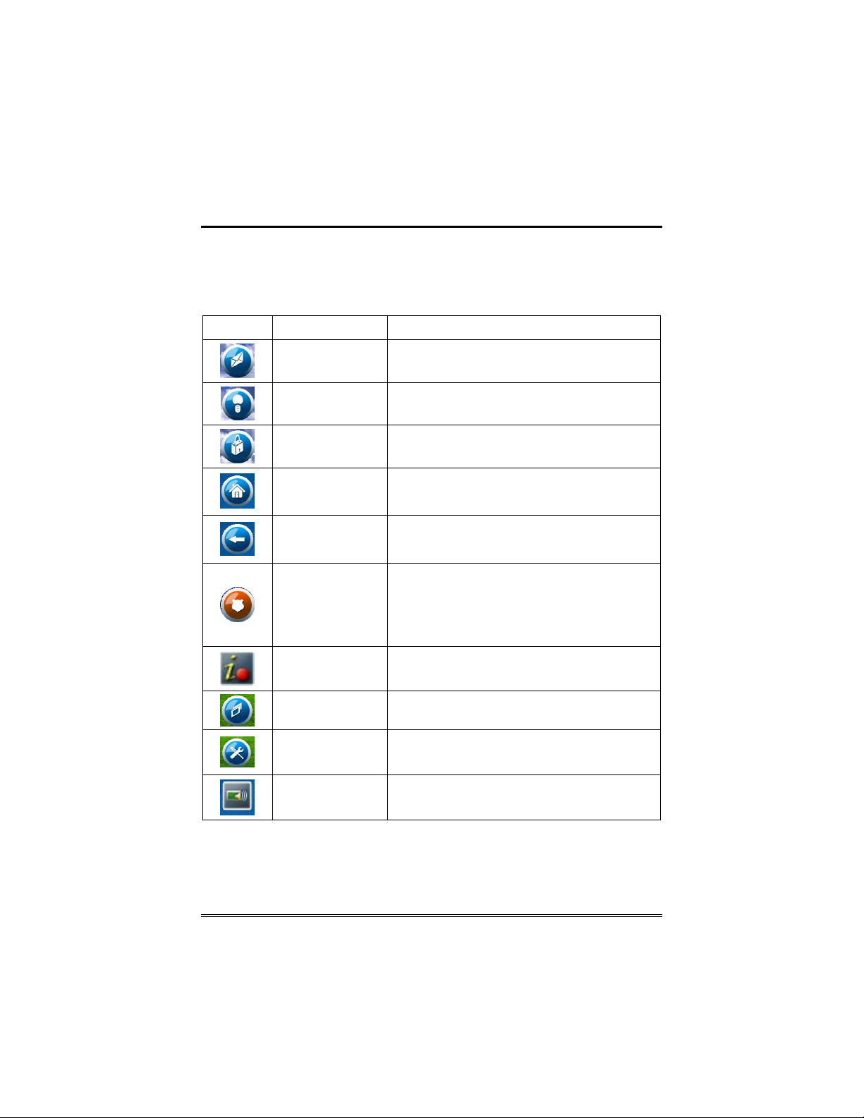
Navigation Icon Descriptions
To aid in the navigation of the TouchCenter, a set of user-friendly
icons has been provided. The appearance, function, and location of
these icons are described below:
ICON LOCATION FUNCTION
"Home" screen
"Home" screen
"Home" screen Acc esses "S ecurity" screen.
Allows you to record and r etrieve v oice
messages.
Allows you to turn certain devices on and off (if
inst al led an d programm ed b y your i ns t al ler. )
Upper left corner
of most scr eens
Upper right corner
of most scr eens
Lower right corner
of screen
Lower right corner
of screen (left of
Date and Time)
Lower le ft corner of
"Home" screen
Lower le ft corner of
"Home" screen
(righ t of Slides how)
Lower le ft corner of
"Security" screen
(right of Partition)
Returns you to the T ouchCenter "Home" screen.
This icon is called the Home button within the
text of this document.
Reverts t o the las t sc r een vi ew ed. T his ic on is
called the Back button w ith i n the t ext of th is
document.
Displays Emergency functions (as programmed by
the installer). This icon is called the Panic but t on
within the text of this d ocu men t.
Note: This ic on is displayed an d ac t i ve on all
screens except while in the Clean Screen mode
and during an LCD Display test in Diagnostics.
This ic on al erts the user to a Contr ol Panel
Message.
"Slideshow" icon. Allows manual start to the slide
show.
"Setup" icon. Allows access to Setup menus.
"Voic e Status " ic on. Allows user to hear sys t em
status.
8
About the TouchCenter (Cont'd)
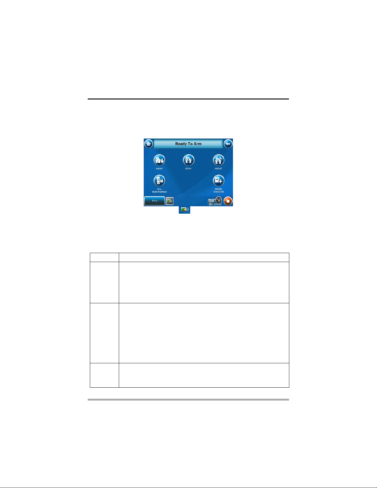
TouchCenter "Arming" Screen
From the "Home" screen, press SECURITY to access the TouchCenter
"Arming" screen. Use this picture and the table that follows to
become familiar with the TouchCenter security functions.
Note: The Voice Status Icon (
indicates the TouchCenter Voice feature. This button causes the
TouchCenter to announce system status if pressed at least 10 seconds
following its last press. Note that Voice must be enabled (by the
installer) for this button to function correctly during an alarm
condition.
ITEM FUNCTION
AWAY Press this but t on to arm when n o one w il l be st ayi ng on the pr emises.
STAY
NIGHT Press this bu tt on to arm when you are staying h om e and do not expe c t
When arm ed in AWAY, the system wi ll s ound an al ar m if a pr ot ect ed d oor
or window is op ened, or if any mov em ent is detect ed ins ide the prem ises.
You may lea ve through t h e entrance door dur i ng the exit del a y p eriod
withou t c aus in g an al arm. You m ay also re-enter t hr ou gh the entr anc e door,
but must disarm the s yst em wit h you r User Code wi thin the entr y d el ay
period or an alarm will occur.
Press th is butt on to arm when you are staying h o m e, bu t might expect
someone to use the entr ance door lat er.
When arm ed in STAY, the system will sound an al arm if a prot ected door or
window is op en ed, b ut you m ay otherwise move fr eel y throughout th e
premises. Late arrivals can enter through the entrance door without causing
an alarm, but they must disarm the system wit h in the entry del ay p eriod or
an alarm wi ll oc c ur.
NOTE: On some residential systems, if you press the Voice Status Icon
while armed in the Stay Mode, the exit delay time will restart (if the feature
was enabl ed by your inst aller).
anyone t o us e the entranc e door .
NIGHT Mode differently; have him/her describe the actual settings of this
mode.
) shown in the above illustration
Your installer may have conf igu red
9
About the TouchCenter (cont'd)
ITEM FUNCTION
Arm MultiPartitions
MORE
CHOICES
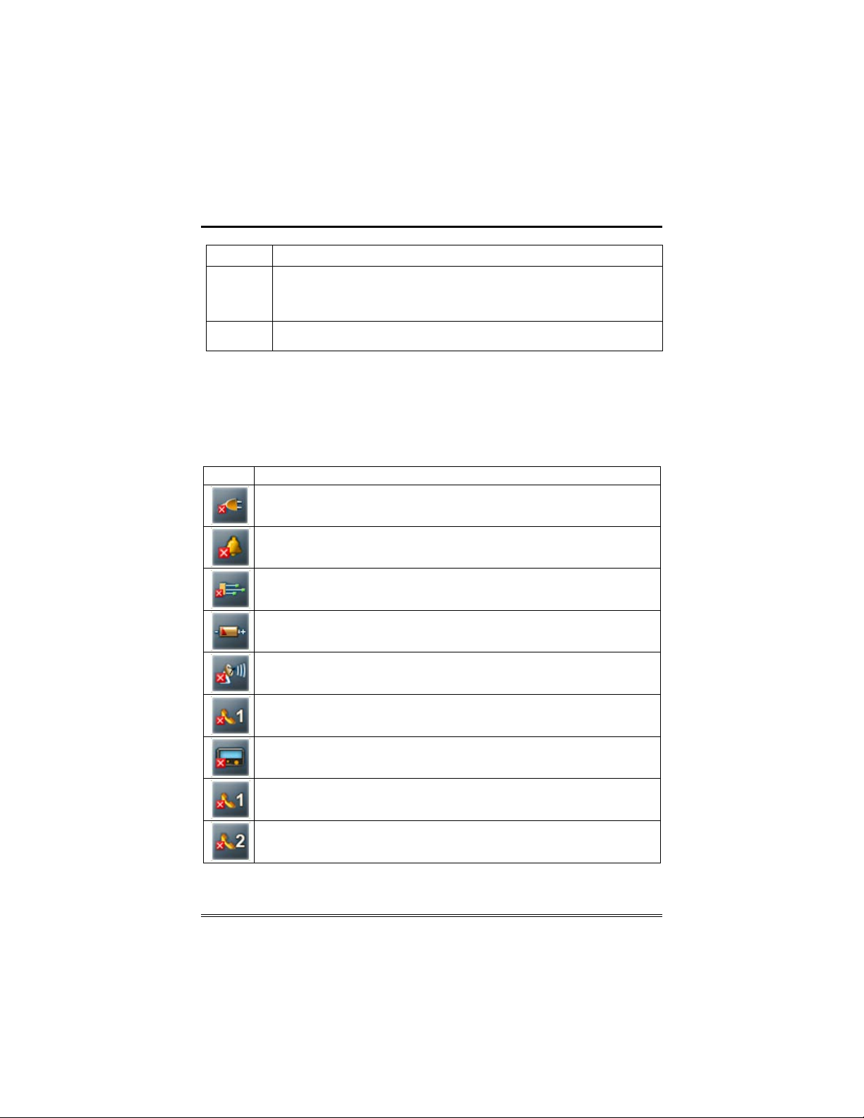
System Troubles
The “Arming” screen also displays an Icon(s) if a system trouble(s)
occurs. The system trouble Icon is displayed to the left of the Panic
button. If a trouble Icon is shown, contact your alarm company. The
following Icons may be shown as applicable to your system:
ICON MEANING
Press this button when y ou wan t to ar m m or e th an one partiti on . All
partitions w ithin the s yst em c an b e ar m ed at on e time (if the user is so
authorized). Note: This option may not be shown for some single partition
systems.
Press this button for more Security, Lighting, and TouchCenter setup
features.
AC Loss – The system is not receiving AC power.
Bell Failure – The system bell or siren has a problem. Note: This Icon will be
displayed when interfacing with residential panels only.
Expand er Fai lure – The syst em h as a failure in an exp ansion m odu l e.
Low Battery – The system battery, that powers the system during an AC
power loss, is low.
LRR Supervision Failure – The Long Range Radio used to communicate with
the central station has a supervision failure
Max Attempts Exceeded – The system has exceeded the maximum attempts
to communicate with the Central Station.
Pager Failure – The system cannot communicate with an assigned pager.
Telco-1 Cut – The system is not able to communicate with the central
monitor ing station o ver t h e primary phon e line.
Telco-2 Cut – The system is not able to communicate with the central
monitor ing station o ver th e s ec ond ary phone lin e.
Note: Fault Icon(s) will sc r oll between all f aults present on th e s ystem, if multip le faults
exist.
10

System Overview
Introduction to Your System
This system offers you burglary protection and may offer fire, carbon
monoxide and emergency protection. Monitoring is accomplished
with various contact and motion sensors for perimeter and interior
burglary protection, plus the system may have strategically placed
smoke, heat, carbon monoxide or combustion detectors.
Burglary Protection
The burglary protection portion of your system must be turned on or
"armed" before it will sense burglary alarm conditions. Your system
provides three modes of burglary protection: Away, Stay, and Night,
and even allows you to “bypass” selected zones of protection while
leaving the rest of the system armed (e.g. this enables you to arm the
system but leave upper-story windows open.)
The system also provides a Chime mode in all keypads, and Voice
mode, for alerting users to the opening and closing of doors and
windows even while the system is disarmed.
Partitions
This system may be configured to arm and disarm more than one
area, each as if it had its own control. These areas are called
partitions. Partitions are used when the user wants to disarm certain
areas while leaving other areas armed, or to limit access to certain
areas to specific individuals. Each user of the system can be
authorized to operate all or only some partitions, and can be given
different privileges in each. Information about Partitions is
presented later in this document.
Zones
Your system's sensing devices have been assigned to various "zones."
For example, the sensing device on your Entry/Exit door may have
been assigned to zone 01, sensing devices on windows in the master
bedroom to zone 02, and so on. These numbers will appear on the
display, along with an alpha descriptor for that zone (if programmed),
when an alarm or trouble condition occurs.
Entry/Exit Delays
Your system has preset time delays, referred to as exit delay and
entry delay. Whenever you arm your system, exit delay gives you
11

System Overview (Cont'd)
time to leave through the designated exit door without setting off an
alarm. Exit delay begins immediately after entering any arming
command, and applies to all modes of arming protection. If
programmed, a slow beeping will sound throughout the exit delay
period. Additionally if programmed, a rapid beeping may sound
during the final 10 seconds of the exit delay period.
Note: On some systems, pressing the Voice Status Icon restarts the
exit delay. Refer to your control panel User Guide to see if this is
applicable on your system.
Entry delay gives you time to disarm the system when you enter
through the designated entrance door. But the system must be
disarmed before the entry delay period ends, or an alarm will occur.
The keypad will beep during the entry delay period, reminding you to
disarm the system. Ask your installer about the delay times
programmed into your system.
Alarms
When an alarm occurs, the TouchCenter (and any other keypads) and
external sounders will sound, and the zone(s) causing the alarm are
displayed. If your system is connected to a central monitoring station,
an alarm message will also be sent. To stop the alarm sounding,
simply disarm the system.
Memory of Alarm
When an alarm condition occurs, the number(s) of the zone(s) that
caused the problem are displayed, along with the type of alarm. These
remain displayed until cleared.
Note: If you change screens, the alarm in memory can be viewed and
cleared by selecting the Display Faults button on the Arming Screen.
Fire Protection
The optional fire protection portion of your security system (if used) is
always on and will sound an alarm if a fire condition is detected.
Note: If a fire or smoke detector develops a low battery, a “Fire
Maintenance” message is displayed. To determine which zone is
causing the problem, go to “Display Faults” to determine which zone
has the low battery indication.
Carbon Monoxide Protection
The optional carbon monoxide protection portion of your security
system (if used) is always on and will sound an alarm if a carbon
monoxide condition is detected.
12
System Overview (Cont'd)
Note: If a carbon monoxide detector develops a low battery, a
“Carbon Monoxide Maintenance” message is displayed. To determine
which zone is causing the problem, go to “Display Faults” to
determine which zone has the low battery indication.
User Codes
Each user must be assigned a name with a corresponding 4-digit user
code in order to gain access to various features and functions. Users
for the system are programmed in a central user setup location that
provides the specific questions for authorization level, partition
assignment, and RF button assignment.
Extended Functionality
Extended functions are advanced functions that can be accessed
through a standard alpha keypad or through the console emulation
mode on your TouchCenter touch screen. Refer to your Control Panel
User Guide for these features.
LED Operation
The TouchCenter has three LEDs labeled - ARMED, READY and
MESSAGE. The ARMED LED is red, READY LED is green and
MESSAGE LED is yellow. Each LED's on and off state has different
meanings as described below.
LED DESCRIPTION
*ARMED
*READY
MESSAGE
(Voice models
only)
*Note: If the EN50131 Displ ay feature is enabled, the "Armed" and
"Ready" status LEDs turn OFF until a valid user code is entered.
Safe Mode
The TouchCenter contains a Safe Mode of operation. In the rare event
that the TouchCenter cannot successfully communicate in its graphic
mode with the control panel, the Safe Mode is a backup mode that
ensures that you can communicate with your system.
ON – Security system is armed.
OF F – S ecurity system is not armed.
ON – Security system is disarmed and ready to arm.
OFF – Securi t y s ys t em is ar m ed or disarmed b ut not ready. If
disarm ed, faults or troub l es are present.
FLASHING – The system contains new message(s) for the
User
OFF – No new messages.
13
Security
Introduction to Security System Operation
You can arm your system in one of three arming modes: Away, Stay,
and Night. The following table lists the three different arming modes
and the results of each.
FEATURES FOR EACH ARMING MODE
Arming
Mode
Away Yes Yes Yes Yes
Stay Yes Yes Yes No
Night* Yes Yes (set for Away or
*Your installer may have configured Night Mode differently; have
your installer write the actual zone settings above.
How to Arm the System
Exit
Delay
Entry
Delay
Stay Mode)
No (set for Instant or
Maximum Mode)
Perimeter
Armed
Yes Yes (set for Away
Interior
Armed
or Maximum
Mode)
No ( set for Stay or
Instant Mode)
Arming the system in any mode is performed in the same way, as
described below.
Note: Close all perimeter windows and doors before arming.
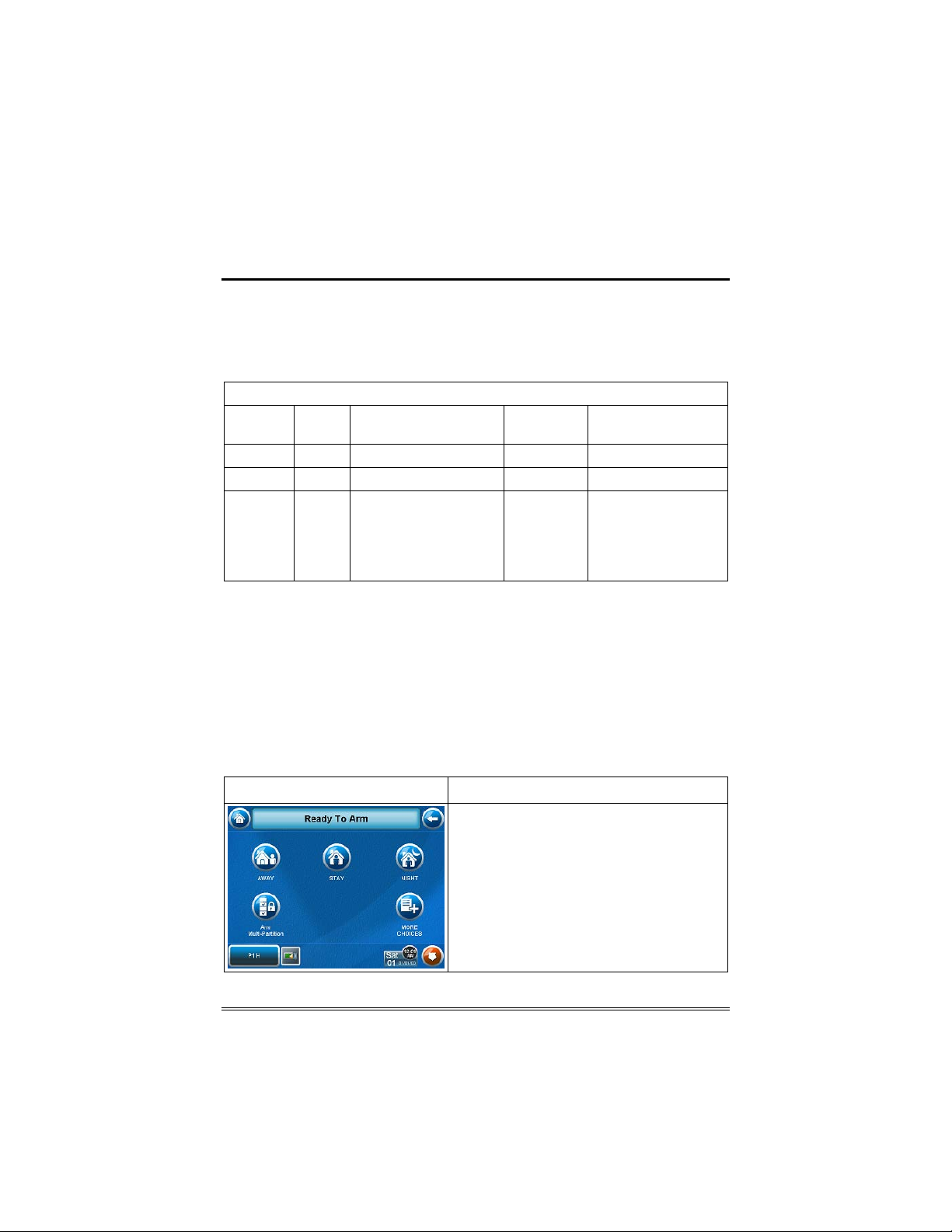
1. F r om t h e "H om e" s creen, p r ess t h e SECURITY but t on. The " Ar min g " s cr een
is displayed.
SCREEN ACTION
2. On the "Arming" screen, press the
selected arming button.
Note: If Quick Arm is Not enabled in your
system, you will rece ive a message to
enter your User Code.
14
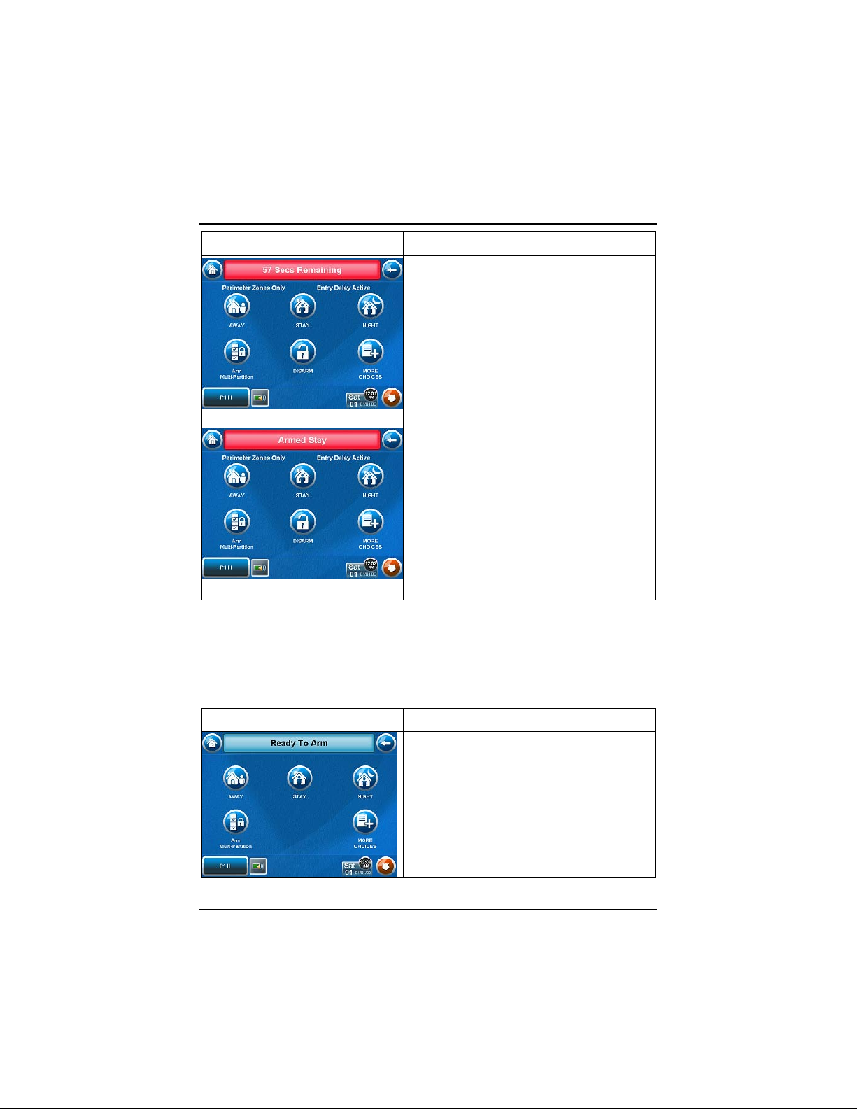
SCREEN ACTION
Arming (typical)
Security (Cont'd)
• The TouchCent er beeps twi ce (Aw ay
and Night Maximum Modes) or 3 times
(Stay and Night Instant Modes)
• a DISARM button appears
• a text message appears stating which
zones are arming and whether or not
there is a n entr y delay
• the screen changes to display the
remaining exit delay time, and
• The exit delay time continues to count
down to one.
Wh en exit delay t i me expi res, t he screen
automatically changes to indicate the
system is "Armed". The system is now
armed in the selected mode.
Armed (typical)
How to Arm Multiple Partitions
Note: Some systems may not have multiple partitions and the “Arm
Multi-Partitions” button may not be displayed.
To arm multiple partitions:
1. F r om t h e "H om e" s creen, p r ess t h e SECURITY but t on. The " Ar min g " s cr een
is displayed.
SCREEN ACTION
2. Press the Arm Multi-Partition button.
15
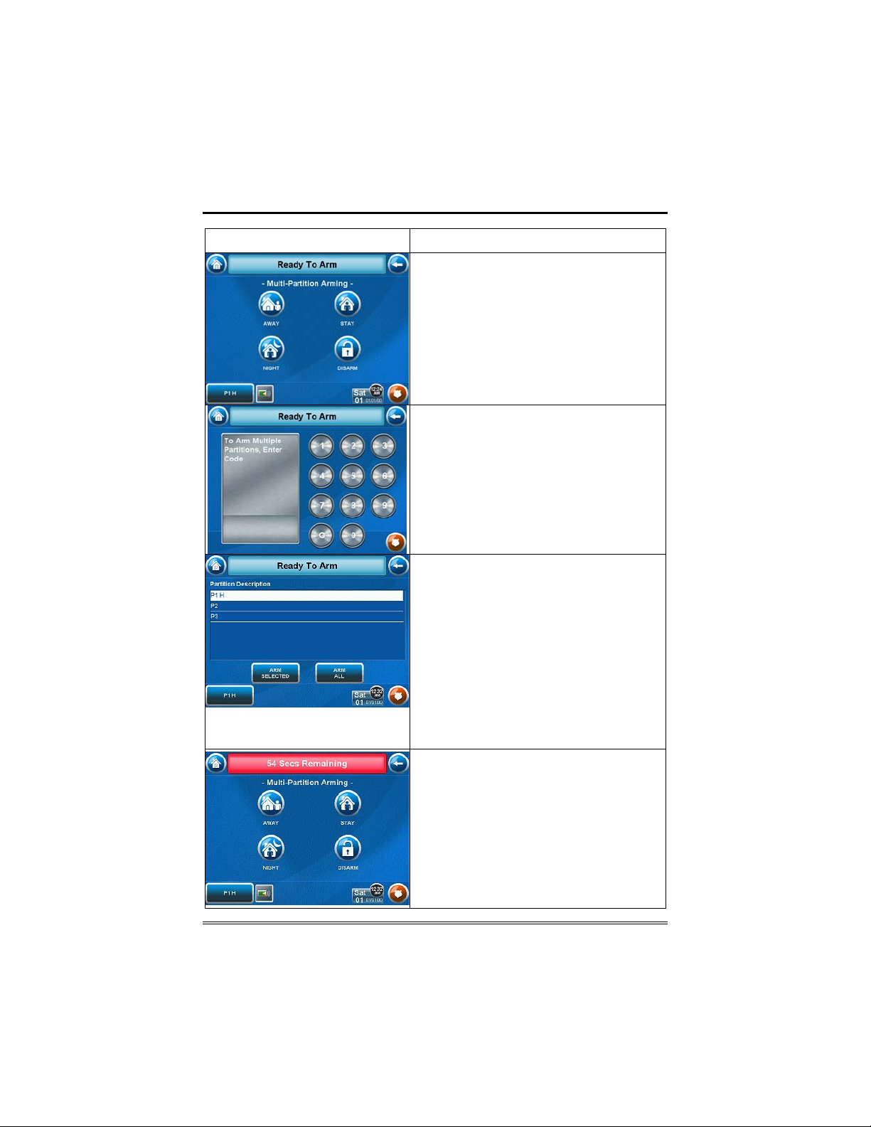
Security (Cont'd)
SCREEN ACTION
3. Press the appropriate arming mode
button.
Note: If any zones are bypassed, a
Display Faults button will also be
displayed on this screen.
4. When prompted , enter th e user code
authorized to access other partition(s).
If the user code is accepted, the system
displays the partitions that the user has
access to.
Note: A user may have access to some or
all of th e available part itio ns.
You have two arming options:
• To arm one or more partitions,
highlight the partition(s) to be armed by
touching it on the screen, then press
ARM SELECTED.
• Press ARM ALL to arm all availa ble
partitions.
• The screen changes to display the
remaining exit delay time, and the exit
delay time continues to count down to
zero.
16
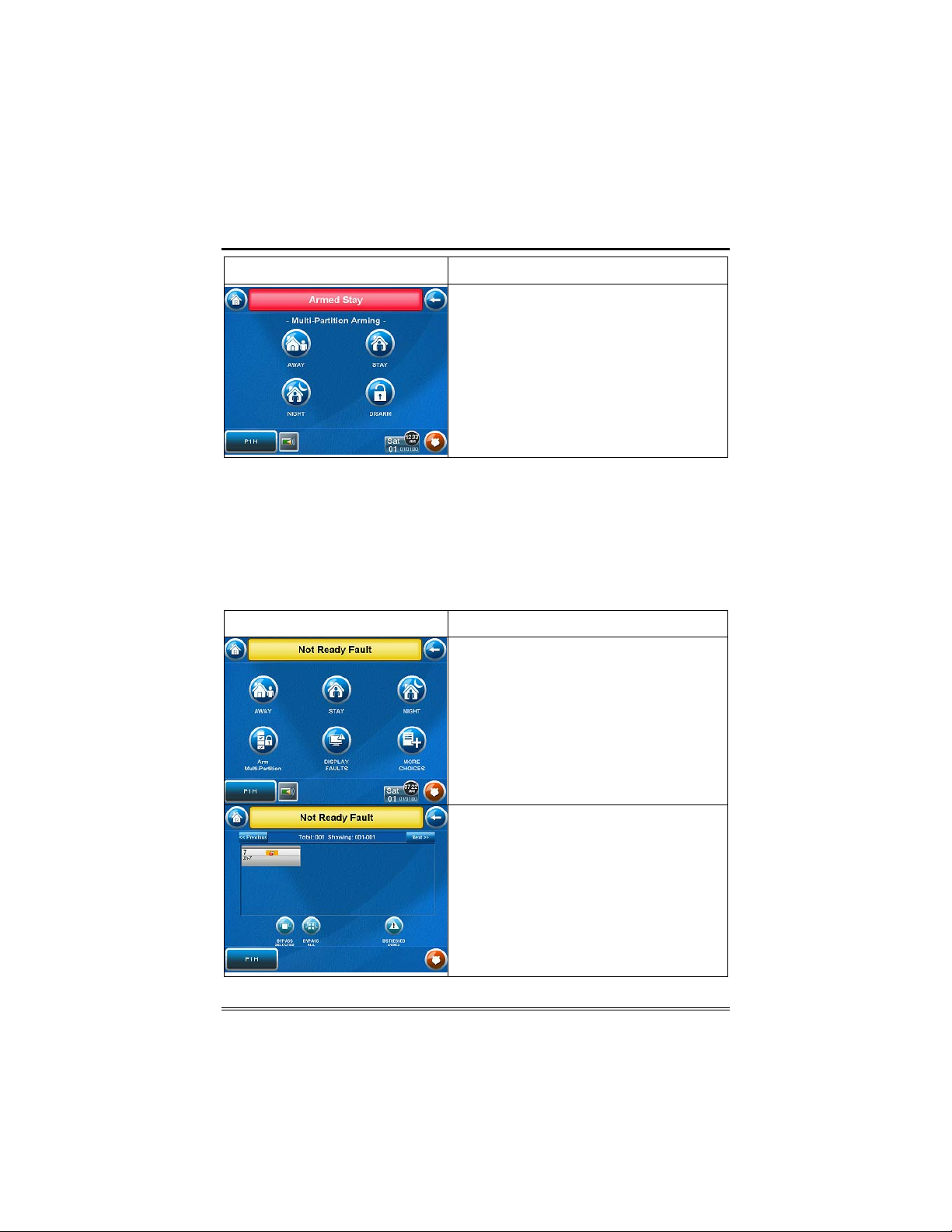
Security (Cont'd)
SCREEN ACTION
• When exit del ay time expir es, th e
screen au tomatica lly changes to
indicate the system is "Armed". The
system is now armed in the selected
mode.
How to Display Faults
The Display Faults function is used when you see a Not Ready Fault
message and want to determine where the fault is and what type of
fault it is.
To display faults do the following:
1. F r om t h e "H om e" s creen, p r ess t h e SECURITY but t on. The " Ar min g " s cr een
is displayed.
SCREEN ACTION
2. Fr om the " Arming" sc reen, press the
Display Faults button. The "Display
Fau l ts" screen is displayed sh owing a
listing of faulted and/or bypassed zones.
3. As applicable, take corrective action
such as closing a window or door to
correct the fault. If the fault cannot be
corrected, you may choose to bypass a
zone by touching the zone to select it and
pressing the BYPASS SELECTED button
or bypass all faulted zones by pressing
the BYPASS ALL button.
17
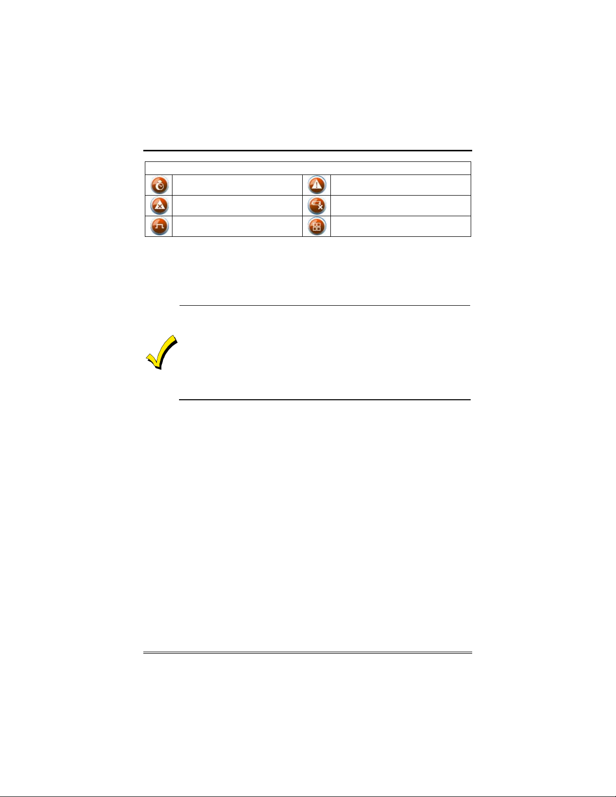
Security (Cont'd)
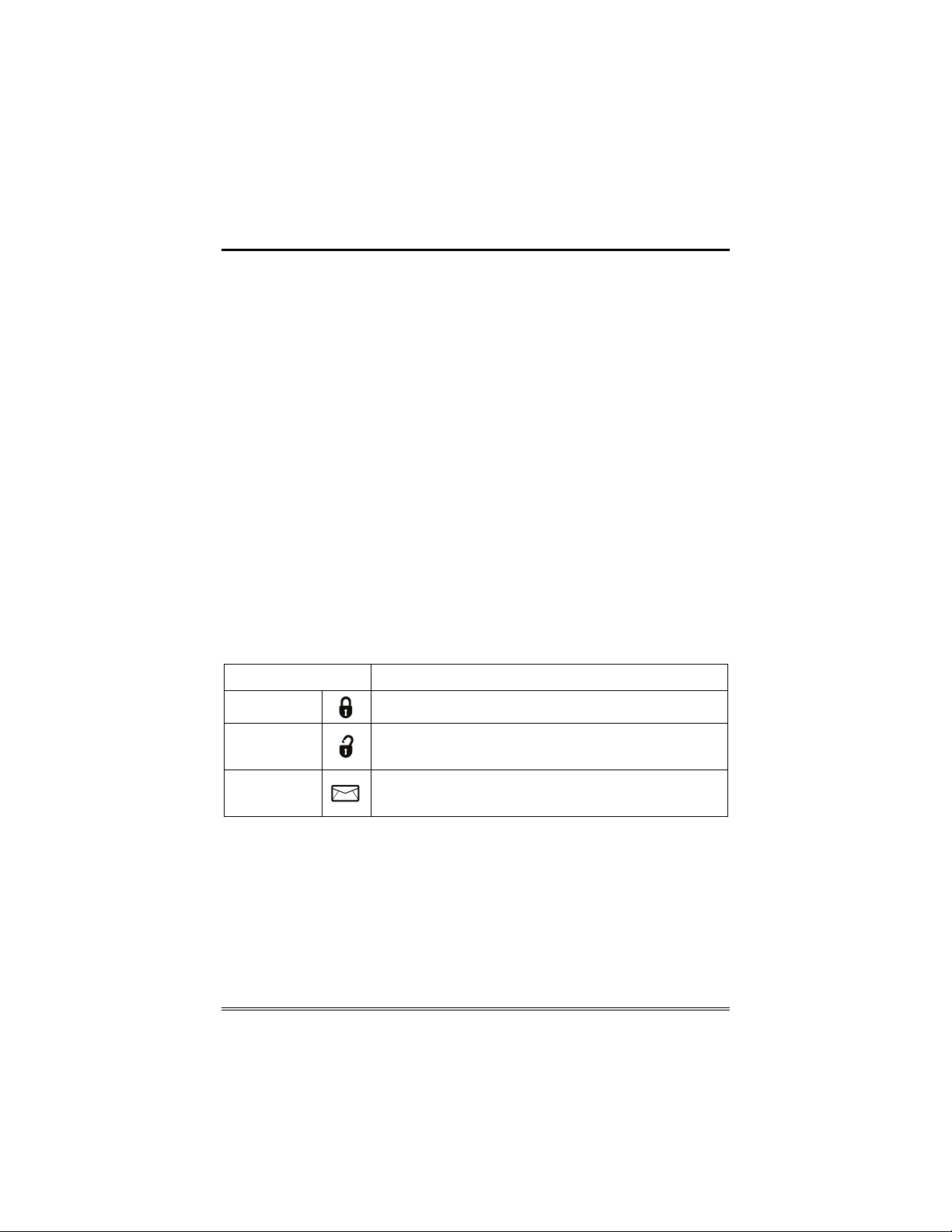
The following symbols may be displayed on the "Display Faults" screen.
Zone in alarm
Zone is faulted
Zone is bypassed
Zone has trouble
Zone has low battery
All
How to Bypass Zones
The Bypass function is used when you want to arm your system with
one or more zones left open. Bypassed zones are unprotected and will
not cause an alarm when violated while your system is armed.
• Residential systems will not allow you to bypass fire, carbon
monoxide or emergency zones. On commercial systems, a specified
user may be allowed to bypass fire, carbon monoxide and system
zones if the user was enabled by your system installer.
• To bypass zones, the system must be disarmed first.
• Limits apply as to how many zones can be bypassed at one time.
These limits are ten zones on residential systems and five zones on
commercial systems.
18
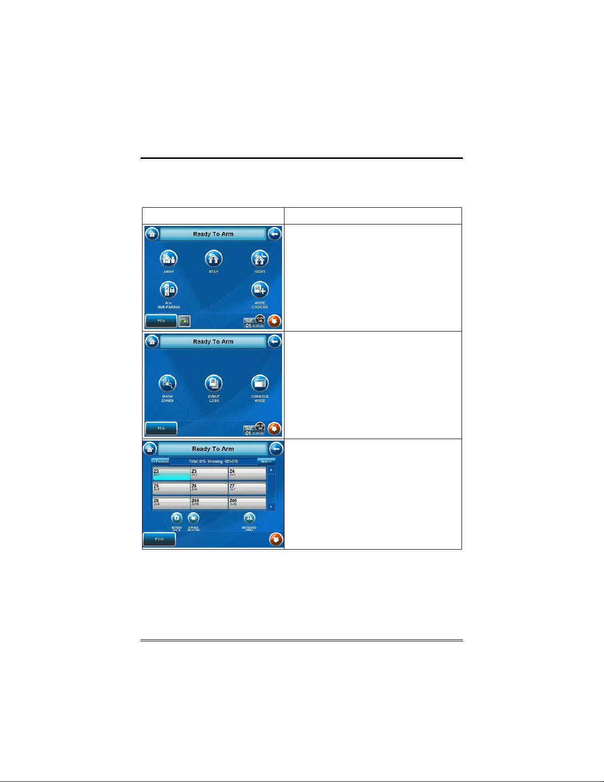
Security (Cont'd)
To bypass zones do the following:
1. F r om t h e "H om e" s creen, p r ess t h e SECURITY but t on. The " Ar min g " s cr een
is displayed.
SCREEN ACTION
2. Fr om the " Arming" sc reen, press the
More Choices button. The "More
Choices" screen is displayed.
Note: If any zones are bypassed or
faulted, a Display Faults button will also
be displayed on this screen.
3. Press the SHOW ZONES button on
the " M ore Ch oic es" scr een.
While the TouchCenter is requesting and
receiving the zone d ata from th e contr ol
panel, the screen displays "Please Wait!".
Then the zones, along with t heir curren t
status, are displayed.
4. Highlight the zone(s) to be bypassed
by touching it on the screen w hen the
zones are displayed.
5. Press the BYPASS SELECTED button.
19
Security (Cont'd)
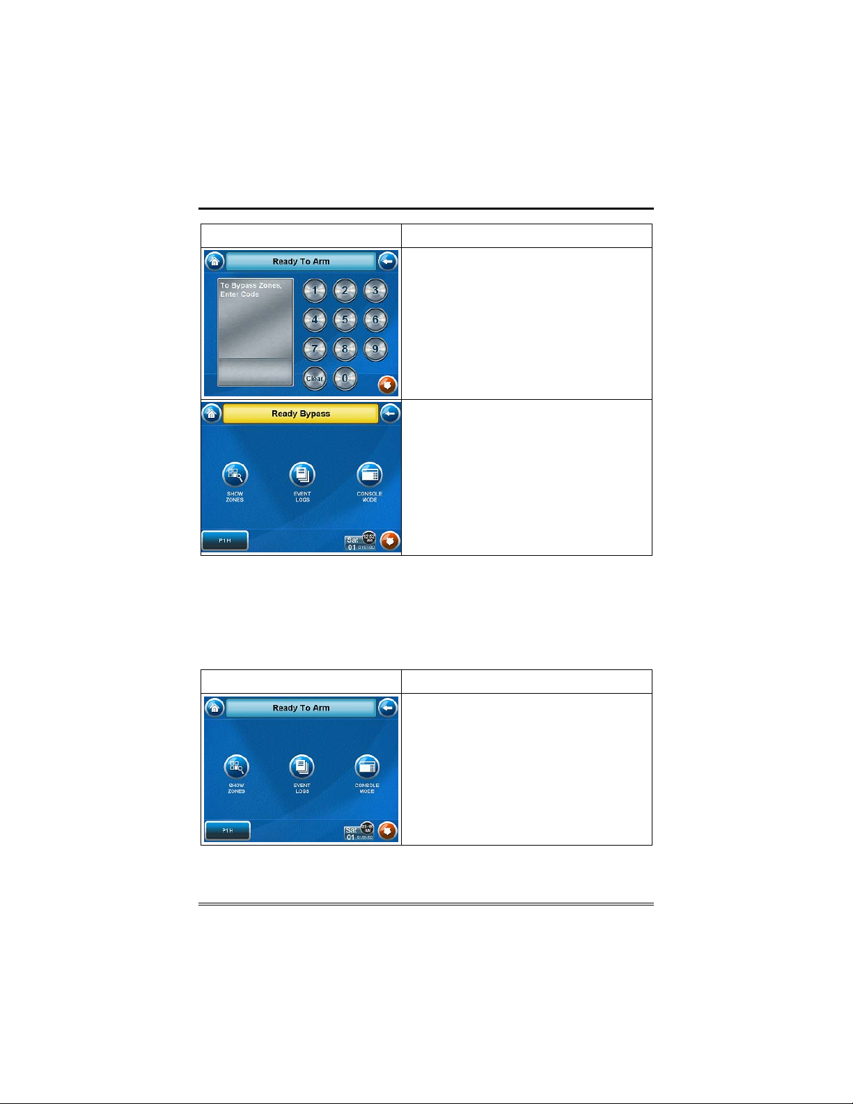
SCREEN ACTION
The "User A uthorizatio n" screen is
displayed with the instructions "To
Bypass Zones, Enter Code".
Note: If zones have already been
bypassed, the top of this screen will
indicate “Rea dy By pass” .
6. Enter your 4-digit user code.
The "More Choices" screen is displayed
showing the syste m status as Ready-
Bypass
7. Press the BACK butto n to return to th e
“Arming”screen .
How to Remove Bypassed Zones
A bypassed zone will automatically be unbypassed when you disarm
the system. If a zone is bypassed, you can remove the bypass as
follows:
SCREEN ACTION
1. View bypassed zones by pressing the
SHOW ZONES button.
While the TouchCenter is requesting and
receiving the zone d ata from th e contr ol
panel, the screen displays "Please Wait!".
Then the zones, along with t heir curren t
status, are displayed.
20
 Loading...