

Page 1

5X10/5X80
5010/80, 5110/80, 5310/80
User’s Guide
Page 2

Disclaimer
Honeywell International Inc. (“HII”) reserves the right to make changes in specifications and other information contained in this document without prior notice,
and the reader should in all cases consult HII to determine whether any such
changes have been made. The information in this publication does not represent a commitment on the part of HII.
HII shall not be liable for technical or editorial errors or omissions contained
herein; nor for incidental or consequential damages resulting from the furnishing, performance, or use of this material.
This document contains proprietary information that is protected by copyright.
All rights are reserved. No part of this document may be photocopied, reproduced, or translated into another language without the prior written consent of
HII.
© 2002-2012 Honeywell International Inc. All rights reserved.
Other product names or marks mentioned in this document may be trademarks
or registered trademarks of other companies and are the property of their
respective owners.
Web Address:
www.honeywellaidc.com
Page 3

FCC/CE
The 5010/5080 or 5110/80 Image Engine, integrated into an OEM device, may
require testing by the OEM to insure compliance with the following federal
regulations:
47 CFR Part 15
EC’s Electromagnetic Compatibility Directive (2004/108/EC) and Low
Voltage Directive (2006/95/EC)
For CE-related inquiries, please contact:
Honeywell Imaging & Mobility - Europe BV
Nijverheidsweg 9-13
5627 BT Eindhoven
The Netherlands
Honeywell shall not be liable for use of our product with equipment (i.e., power
supplies, personal computers, etc.) that is not CE marked and does not comply
with the Low Voltage Directive.
CB Scheme
IEC 60950-1 Second Edition
UL/c-UL (Recognized Component)
UL 60950-1 Second Edition, 2007-03-27
CSA C22.2 No. 60950-1-07, 2nd Edition, 2007-03
LED Safety Statement
LEDs have been tested and classified as “EXEMPT RISK GROUP” to the standard IEC 62471:2006.
Laser Safety Statement
LASER has been tested and classified as a “Class 1 LASER Product” to the
standard IEC 60825-1(2007) Second Edition for 5310/5380 models only.
The Standard also states that the following be included in all user documentation, spec sheets, and brochures, which describe this product:
Caution: Use of controls or adjustments or performance of procedures other
Note: This warning states that altering the inner parts of the laser engine in a
than those specified herein may result in hazardous radiation exposure.
way not specified in the user guide may cause light levels to exceed Class
1 limits. It is not an issue when using under normal conditions.
Legal - i
Page 4

ESD Precautions
The 5X10/80 is shipped in ESD safe packaging. Use care when handling the
scan engine outside its packaging. Be sure grounding wrist straps and properly
grounded work areas are used.
Dust and Dirt
The 5X10/80 must be sufficiently enclosed to prevent dust particles from
gathering on the imager and lens. Dust and other external contaminants will
eventually degrade unit performance.
Legal - ii
Page 5

Table of Contents
Chapter 1 - Getting Started
Introduction ................................................................. 1-1
About This Manual ...................................................... 1-1
Unpacking the Engine ................................................. 1-1
OEM Engine Models ................................................... 1-2
Connecting the Development Engine to the PC.......... 1-3
Chapter 2 - Getting Connected
Plug and Play .............................................................. 2-1
RS-232 .................................................................. 2-1
IBM SurePos ......................................................... 2-1
USB HID................................................................ 2-2
USB COM Port Emulation..................................... 2-2
Chapter 3 - Terminal Interfaces
Terminal ID.................................................................. 3-1
Supported Terminals................................................... 3-1
RS-232 Baud Rate ................................................ 3-2
RS-232 Word Length: Data Bits, Stop Bits,
and Parity .............................................................. 3-3
RS-232 Receiver Time-Out................................... 3-4
RS-232 Handshaking ............................................ 3-4
TTL Level 232 Interface ........................................ 3-5
Chapter 4 - Output
Image VGA.................................................................. 4-1
1
Page 6

Good Read Indicators..................................................4-1
Beeper – Good Read.............................................4-1
Beeper Volume – Good Read................................ 4-2
Beeper Pitch – Good Read....................................4-2
Beeper Duration – Good Read ..............................4-3
LED – Good Read .................................................4-3
LED Good Read Polarity .......................................4-3
Number of Beeps – Good Read ............................4-4
Beep Polarity .........................................................4-5
Good Read Delay ........................................................4-5
User-Specified Good Read Delay................................4-6
Trigger Modes..............................................................4-6
Manual/Serial Trigger ............................................4-6
Snap and Ship .......................................................4-7
Host Notify Mode ...................................................4-8
Scan Stand Mode ........................................................4-8
Scan Stand Symbol ...............................................4-8
Presentation Mode.......................................................4-9
Presentation LED Behavior after Decode..............4-9
Presentation LED Time-Out................................... 4-9
Presentation Sensitivity .......................................4-10
Hands Free Time-Out................................................ 4-10
Reread Delay.............................................................4-11
User-Specified Reread Delay ....................................4-11
LED Power Level....................................................... 4-12
Illumination Lights...................................................... 4-12
Imager Time-Out........................................................4-13
Aimer Delay ...............................................................4-13
User-Specified Aimer Delay................................. 4-13
Aimer Modes..............................................................4-14
Thermal Considerations....................................... 4-15
Centering ...................................................................4-15
Decode Search Mode................................................ 4-17
Output Sequence Overview.......................................4-19
Output Sequence Editor ......................................4-21
Require Output Sequence ...................................4-21
Multiple Symbols........................................................4-22
2
Page 7

No Read .................................................................... 4-23
Print Weight............................................................... 4-24
Video Reverse........................................................... 4-24
Working Orientation .................................................. 4-25
Chapter 5 - Data Editing
Prefix/Suffix Overview ................................................. 5-1
To Add a Prefix or Suffix: ............................................ 5-2
To Clear One or All Prefixes or Suffixes:............... 5-3
To Add a Carriage Return Suffix to All
Symbologies.......................................................... 5-3
Prefix Selections.................................................... 5-4
Suffix Selections.................................................... 5-4
Function Code Transmit........................................ 5-4
Intercharacter, Interfunction, and Intermessage
Delays ......................................................................... 5-5
Intercharacter Delay.............................................. 5-5
User Specified Intercharacter Delay...................... 5-6
Interfunction Delay ................................................ 5-6
Intermessage Delay .............................................. 5-7
Chapter 6 - Data Formatting
Data Format Editor Introduction .................................. 6-1
To Add a Data Format........................................... 6-1
Other Programming Selections ............................. 6-2
Data Format Editor Commands............................. 6-2
Data Format Editor................................................ 6-4
Data Formatter ...................................................... 6-5
Alternate Data Formats ......................................... 6-5
3
Page 8

Chapter 7 - Symbologies
Message Length Description .......................................7-2
Codabar Start/Stop Characters.............................7-3
Codabar Check Character .....................................7-3
Codabar Concatenation.........................................7-4
Codabar Message Length .....................................7-5
Code 39 Start/Stop Characters .............................7-6
Code 39 Check Character .....................................7-6
Code 39 Message Length...................................... 7-7
Code 39 Append....................................................7-8
Code 32 Pharmaceutical (PARAF) ........................7-8
Full ASCII............................................................... 7-9
Code 39 Code Page ............................................7-10
Check Digit ..........................................................7-10
Interleaved 2 of 5 Message Length .....................7-11
Code 93 Message Length.................................... 7-12
Code 93 Code Page ............................................7-13
Straight 2 of 5 Industrial Message Length ...........7-14
Straight 2 of 5 IATA Message Length..................7-15
Matrix 2 of 5 Message Length .............................7-16
Check Digits Required .........................................7-17
Code 11 Message Length.................................... 7-18
ISBT 128 Concatenation...................................... 7-19
Code 128 Message Length.................................. 7-20
Code 128 Code Page ..........................................7-20
Telepen Output ....................................................7-21
Telepen Message Length ....................................7-21
UPC-A Check Digit ..............................................7-22
UPC-A Number System.......................................7-23
UPC-A Addenda ..................................................7-23
UPC-A Addenda Required................................... 7-24
UPC-A Addenda Separator .................................7-24
4
Page 9

UPC-A/EAN-13 with Extended Coupon Code........... 7-24
UPC-E0 Expand.................................................. 7-25
UPC-E0 Addenda Required ................................ 7-26
UPC-E0 Addenda Separator............................... 7-26
UPC-E0 Check Digit............................................ 7-26
UPC-E0 Number System .................................... 7-27
UPC-E0 Addenda................................................ 7-27
EAN/JAN-13 Check Digit..................................... 7-29
EAN/JAN-13 Addenda......................................... 7-29
EAN/JAN-13 Addenda Required......................... 7-30
EAN/JAN-13 Addenda Separator........................ 7-30
ISBN Translate.................................................... 7-30
EAN/JAN-8 Check Digit....................................... 7-31
EAN/JAN-8 Addenda........................................... 7-32
EAN/JAN-8 Addenda Required........................... 7-32
EAN/JAN-8 Addenda Separator.......................... 7-32
MSI Check Character.......................................... 7-33
MSI Message Length .......................................... 7-34
Plessey Message Length .................................... 7-35
RSS Expanded Message Length ........................ 7-37
PosiCode A and B............................................... 7-38
PosiCode Message Length ................................. 7-39
Codablock F Message Length............................. 7-40
Code 16K Message Length................................. 7-41
Code 49 Message Length ................................... 7-42
PDF417 Message Length.................................... 7-43
MicroPDF417 Message Length........................... 7-44
5
Page 10

EAN•UCC Composite Codes.....................................7-44
UPC/EAN Version................................................ 7-45
EAN•UCC Composite Code Message Length ..... 7-45
Postnet................................................................. 7-47
Planet Code .........................................................7-48
British Post........................................................... 7-48
Canadian Post .....................................................7-48
Kix (Netherlands) Post.........................................7-49
Australian Post..................................................... 7-49
Japanese Post .....................................................7-49
China Post Message Length................................ 7-50
Korea Post Message Length ...............................7-51
QR Code Message Length ..................................7-52
Data Matrix Message Length...............................7-53
MaxiCode Message Length .................................7-54
Aztec Code Message Length............................... 7-55
Aztec Runes ........................................................7-55
Chapter 8 - Imaging Commands
Image Snap - IMGSNP................................................ 8-1
IMGSNP Modifiers .................................................8-1
Image Ship - IMGSHP .................................................8-2
IMGSHP Modifiers .................................................8-3
Intelligent Signature Capture - IMGBOX......................8-7
IMGBOX Modifiers.................................................8-7
Chapter 9 - OCR Programming
OCR.............................................................................9-1
OCR Templates........................................................... 9-4
Creating an OCR Template ...................................9-4
Stringing Together Multiple Formats
(Creating “Or” Statements)...............................9-6
OCR User-Defined Variables.......................................9-7
Reading Multi-Row OCR .......................................9-7
6
Page 11

OCR Check Character ................................................ 9-8
OCR Modulo 10 Check Character......................... 9-9
OCR Modulo 36 Check Character......................... 9-9
OCR User-Defined Check Character .......................... 9-9
Weighting Options............................................... 9-10
OCR ISBN Application Example ............................... 9-12
OCR Template Codes............................................... 9-14
Chapter 10 - Utilities
To Add a Test Code I.D. Prefix to All Symbologies... 10-1
Show Software Revision ........................................... 10-1
Show Data Format .................................................... 10-1
Resetting the Standard Product Defaults.................. 10-2
2D PQA (Print Quality Assessment) ......................... 10-2
Visual Menu 2003 ..................................................... 10-3
Installing Visual Menu 2003 from the Web.......... 10-4
Quick*View................................................................ 10-5
Installing Quick*View from the Web .................... 10-5
Chapter 11 - Serial Programming Commands
Conventions .............................................................. 11-1
Menu Command Syntax............................................ 11-1
Query Commands ............................................... 11-2
Concatenation of Multiple Commands ................ 11-2
Responses .......................................................... 11-2
Examples of Query Commands .......................... 11-3
Trigger Commands ................................................... 11-4
Resetting the Standard Product Defaults.................. 11-4
Menu Commands...................................................... 11-5
Chapter 12 - Maintenance
Repairs...................................................................... 12-1
Maintenance.............................................................. 12-1
Cleaning the Imager’s Window............................ 12-1
Inspecting Cords and Connectors....................... 12-1
7
Page 12

Troubleshooting......................................................... 12-2
Chapter 13 - Customer Support
Product Service and Repair.......................................13-1
Technical Assistance................................................. 13-1
Limited Warranty........................................................13-1
Appendix A - Reference Charts
Symbology Chart .........................................................A-1
ASCII Conversion Chart (Code Page 1252)................A-3
Code Page Mapping of Printed Bar Codes..................A-5
8
Page 13

1
Getting Started
Introduction
The 5X10/80 series of products is designed for integration into a wide range of
OEM devices. The engine’s compact mechanical design can drop into many
existing applications, allowing OEMs and third-party manufacturers to integrate
the benefits of image-based scanning into a variety of devices, including
handheld computers (PDTs), medical instrumentation, diagnostic equipment,
and robotics.
Two different decoding configurations provide OEMs the flexibility required to
address various application-specific needs. The 5X10, with linear and PDF417
decoding, delivers "laser-like" reading on linear codes, and point-and-shoot on
stacked codes. The 5X80 full-featured decoder incorporates Honeywell
comprehensive list of decoding capabilities. A Software Developers Kit provides
a simple software interface (APIs) to help ease integration. For software updates
and additional information, visit the Honeywell website at
www.honeywellaidc.com.
About This Manual
This User’s Guide provides demonstration, installation, and programming
instructions for the engine. Product specifications, dimensions, warranty, and
customer support information are also included.
Honeywell’s bar code engines are factory programmed for the most common
terminal and communications settings. If you need to change these settings,
programming is accomplished by scanning the bar codes in this guide.
An asterisk (*) next to an option indicates the default setting.
Unpacking the Engine
After you open the shipping carton containing the OEM Engine, take the
following steps:
• Check to make sure everything you ordered is present.
• Save the shipping container for later storage or shipping.
• Check for damage during shipment. Report damage immediately to the
carrier who delivered the carton.
1 - 1
Page 14

OEM Engine Models
There are three models of the OEM Engine, which may be used with many
interfaces described in this manual. Refer to the chart below to determine the
models that can be used with your interface.
The following interfaces apply to all OEM Engine focal distances and decoding
options.
Models Interface Decoding Capability
a
5X10XX-XXX2
5X10XX-XXX4
5X10XX-XXX3 USB 1.1 Linear
5X80XX-XXX2
5X80XX-XXX4
5X80XX-XXX3 USB 1.1 Linear
a. This output format allows direct connection to a PC RS-232 serial port.
TTL Level 232 inverted
non-inverted
TTL Level 232 inverted
non-inverted
Note: The 5X80 decoded out image engine can be used by customers to
evaluate the 5X00 non decoded out image engine. Refer to the 5X00
Integration Manual for detailed part numbers and integration information.
Linear
Stacked Linear
Stacked Linear
Linear
Stacked Linear
Matrix
Stacked Linear
Matrix
1 - 2
Page 15
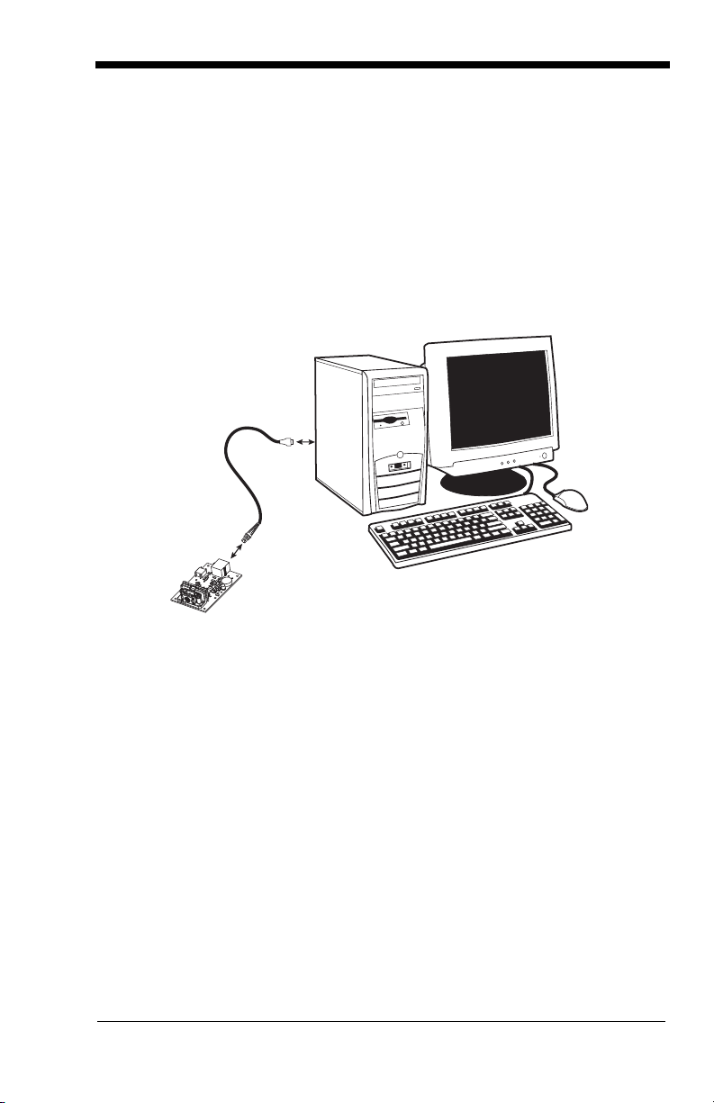
Connecting the Development Engine to the PC
The development OEM Engine can connect to a PC for evaluation.
1. Turn off power to the terminal/computer.
2. If using a USB connection, connect the included interface cable to the
engine and to the matching USB port on the back of the computer. Skip to
step 5.
Note: For additional USB programming and technical information, refer to
Honeywell’s “USB Application Note,” available at
www.honeywellaidc.com
.
1 - 3
Page 16

3. If using an RS-232 connection, connect the serial interface cable to the
RS-232 Interface
engine and to the matching port on the back of the computer.
4. Connect the power supply connector to the serial interface cable. Plug in the
power supply.
5. Turn the terminal/computer power back on. The engine beeps.
6. If connecting the Development Engine using an RS-232 interface, all
communication parameters between the imager and terminal must match for
correct data transfer through the serial port using RS-232 protocol. Scan
the RS-232 interface bar code below. This programs the Development
Engine for an RS-232 interface at 115,200 baud, parity–none, 8 data bits, 1
stop bit, and adds a suffix of a CR LF.
7. Verify the engine operation by scanning a bar code from the Sample
Symbols in the back of this manual. The engine beeps once when a bar
code is successfully decoded.
To connect an 5X10/80 engine to your host system, please refer to the
Integration Manual.
1 - 4
Page 17

Reading Techniques
Linear bar code 2D Matrix symbol
The engine has a view finder that projects a bright red or green aiming beam that
corresponds to the engine’s horizontal field of view. The aiming beam should be
centered over the bar code, but it can be positioned in any direction for a good
read.
The aiming beam is smaller when the engine is closer to the code and larger
when it is farther from the code. Symbologies with smaller bars or elements (mil
size) should be read closer to the unit. Symbologies with larger bars or elements
(mil size) should be read farther from the unit. To read single or multiple
1 - 5
Page 18

symbols (on a page or on an object), hold the engine at an appropriate distance
from the target, send a trigger command, and center the aiming beam on the
symbol. If the code being scanned is highly reflective (e.g., laminated), it may
be necessary to tilt the code +
5° to prevent unwanted reflection.
1 - 6
Page 19

2
RS-232 Interface
IBM SurePos
(USB Handheld Imager)
Interface
IBM SurePos
(USB Tabletop Imager)
Interface
Getting Connected
Plug and Play
Plug and Play bar codes provide instant engine set up for commonly used
interfaces.
Note: After you scan one of the codes, power cycle the host terminal to have
the interface in effect.
RS-232
The RS-232 Interface bar code is used when connecting to the serial port of a
PC or terminal. The following RS-232 Interface bar code also programs a
carriage return (CR) and a line feed (LF) suffix, baud rate, and data format as
indicated below:
Option Setting
Baud Rate 115200 bps
Data Format 8 data bits, no parity bit, 1 stop bit
IBM SurePos
Scan one of the following “Plug and Play” codes to program the OEM Engine for
IBM SurePos (USB Handheld imager) or IBM SurePos (USB Tabletop imager).
Note: After scanning one of these codes, you must power cycle the cash
register.
2 - 1
Page 20

Each bar code above also programs the following suffixes for each symbology:
USB HID Bar Code Imager
USB COM Port Emulation
Symbology Suffix
EAN-8 0C
EAN-13 16
UPC-A 0D
UPC-E 0A
Code 39 00 0A 0B
Interleaved 2 of 5 00 0D 0B
Code 128 00 18 0B
Note: The following USB “Plug and Play” codes (USB Keyboard - PC, USB
Keyboard - Mac, and USB HID) are supported on specific OEM Engine
models. Refer to OEM Engine Models on page 1-2 to determine if this
interface applies to your engine.
USB HID
Scan the following code to program the OEM Engine for USB HID bar code
imagers. Scanning this code changes the terminal ID to 131.
USB COM Port Emulation
Scan the following code to program the OEM Engine to emulate a regular RS232-based COM port. If you are using a Microsoft
to download a driver from the Honeywell website www.honeywellaidc.com
driver will use the next available COM port number. Apple® Macintosh
computers recognize the engine as a USB CDC class device and automatically
use a class driver. Scanning the code below changes the terminal ID to 130.
®
Windows® PC, you will need
). The
Note: No extra configuration (e.g., baud rate) is necessary.
2 - 2
Page 21
RS-232 True and RS-232 TTL
RS-232 True and RS-232 TTL
USB PC Keyboard
USB Mac Keyboard
USB SurePOS (Handheld Imager)
USB IBM SurePOS (Tabletop Imager)
USB PC Keyboard
USB Mac Keyboard
IBM SurePOS (Handheld Imager)
USB IBM SurePOS (Tabletop Imager)
2 - 3
Page 22
USB HID POS
USB HID POS
USB Japanese Keyboard (PC)
On
* Off
On
* Off
USB Japanese Keyboard
CTS/RTS Emulation
ACK/NAK Mode
2 - 4
Page 23

3
Terminal ID
Save
Terminal Interfaces
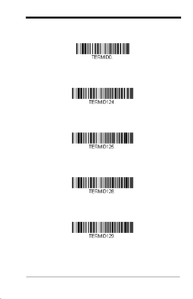
Terminal ID
If you want to change the pre-programmed interface of your image engine, refer
to Supported Terminals, below.
For example, a USB HID POS device has a Terminal ID of 131. You would scan
the Terminal ID bar code, then 1, 3, 1 from the Programming Chart inside the
back cover of this manual, then Save. If you make an error while scanning the
digits (before scanning Save), scan the Discard code on the Programming
Chart, scan the Terminal ID bar code, scan the digits, and the Save code again.
Note: After scanning one of these codes, you must power cycle your computer.
Supported Terminals
Ter mi nal Model(s)
IBM SurePOS USB Handheld Imager
IBM SurePOS USB Tabletop Imager
RS-232 True
RS-232 TTL
USB COM Port Emulation
USB PC Keyboard
USB Mac Keyboard
USB HID POS
USB Japanese Keyboard
Termi nal
ID
128
129
000
000
130
124
125
131
134
3 - 1
Page 24
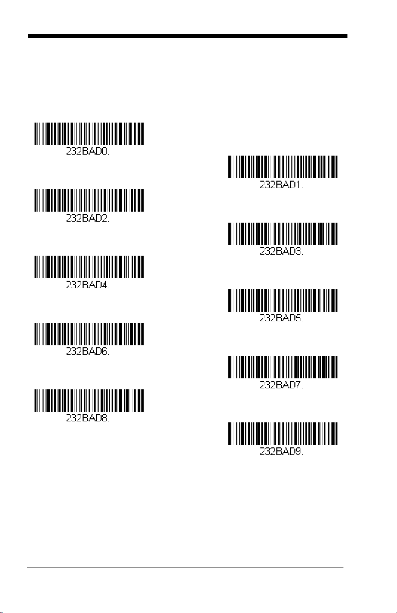
RS-232 Baud Rate
300
2400
600
1200
4800
38400
9600
19200
* 115,200
57,600
Baud Rate sends the data from the imager to the terminal at the specified rate.
The host terminal must be set for the same baud rate as the imager.
Default = 115,200
.
3 - 2
Page 25
RS-232 Word Length: Data Bits, Stop Bits, and Parity
7 Data, 1 Stop, Parity Even
7 Data, 1 Stop, Parity None
7 Data, 1 Stop, Parity Odd
7 Data, 2 Stop, Parity Odd
7 Data, 2 Stop, Parity Even
7 Data, 2 Stop Parity None
* 8 Data, 1 Stop, Parity None
8 Data, 1 Stop, Parity Even
8 Data, 1 Stop, Parity Odd
Data Bits
application requires only ASCII Hex characters 0 through 7F decimal (text, digits,
and punctuation), select 7 data bits. For applications which require use of the
full ASCII set, select 8 data bits per character.
Stop Bits
Parity
Default = None.
sets the word length at 7 or 8 bits of data per character. If an
sets the stop bits at 1 or 2.
provides a means of checking character bit patterns for validity.
Default = 8.
Default = 1.
3 - 3
Page 26

RS-232 Receiver Time-Out
RS-232 Receiver Time-Out
The unit stays awake to receive data until the RS-232 Receiver Time-Out
expires. A trigger command resets the time-out. When an RS-232 receiver is
sleeping, a character may be sent to wake up the receiver and reset the timeout. A transaction on the CTS line will also wake up the receiver. The receiver
takes 300 milliseconds to completely come up. Change the RS-232 receiver
time-out by scanning the bar code below, then scanning digits from the inside
back cover of this manual, then scanning
Save
. The range is 0 to 300 seconds.
Default = 0 seconds (no time-out - always on).
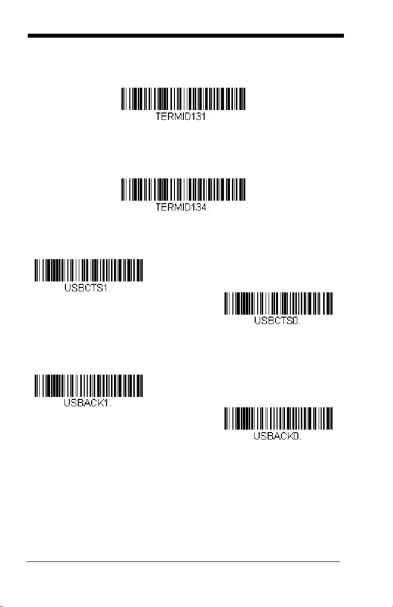
RS-232 Handshaking
RS-232 handshaking is a set of rules concerning the exchange of data between
serially communicating devices.
If using RTS/CTS handshaking, the imager issues an active RTS signal to the
receiving device. The imager waits to send its data until it detects an active CTS
signal from the receiving device. The imager then sends its data while checking
the CTS signal before the transmission of each data character. If an inactive
CTS signal is detected at any time, the imager halts transmission until it detects
another active CTS signal. When the imager has finished transmitting data, it
issues an inactive RTS signal to the receiving device.
XON/XOFF Off, and ACK/NAK Off.
Default = RTS/CTS Off,
3 - 4
Page 27
TTL Level 232 Interface
RTS/CTS On
* XON/OFF Off
* RTS/CTS Off
XON/XOFF On
ACK/NAK On
* ACK/NAK Off
The 5X80 provides a TTL level serial 232 communication link. TTL Level 232
Inverted is the “normal” mode that allows direct communication from the 5X80 to
a standard PC RS-232 serial port with the use of cable (part number 42206139-
04).
Non-Inverted serial TTL communication is provided to allow direct connection to
a TTL UART port, or to an RS-232 driver integrated circuit. Note that if theTTL
Level 232 Non-Inverted bar code is scanned, the 5X80 will no longer
communicate with a standard PC RS-232 port.
TTL Level 232 Inverted with Polarity Override allows direct communication from
the 5X80 to a standard PC RS-232 serial port with the use of cable (part number
42206139-04). This setting also allows you to override the polarity externally.
Note: For further information on the TTL Level 232 Interface, refer to the 5X10/
80 Integration Manual.
3 - 5
Page 28

Default = TTL Level 232 Inverted with Polarity Override.
TTL Level 232 Inverted
TTL Level 232 Non-Inverted
* TTL Level 232 Inverted
with Polarity Override
3 - 6
Page 29

4
Off
* On
* On
Off
Output
Image VGA
You can set the image size to a VGA resolution, if necessary, to accommodate
older applications that require a smaller image size. When Image VGA is set to
On, the resultant image is 640x480 pixels. When Image VGA is Off, your image
is 752x480 pixels.
Good Read Indicators
Beeper – Good Read
The beeper may be programmed On or
this option off, only turns off the beeper response to a good read indication. All
error and menu beeps are still audible.
Note: Changes to Beep Polarity (see page 4-5) also affect the Beeper-Good
Read signal.
Default = On.
Off
in response to a good read. Turning
Default = On.
4 - 1
Page 30
Beeper Volume – Good Read
High
Medium
Off
Low
Low (1600 Hz)
* Medium (3250 Hz)
High (4200 Hz)
The beeper volume codes modify the volume of the beep the imager emits on a
good read.
Default = Medium for the 5X10, High for the 5X80.
Beeper Pitch – Good Read
The beeper pitch codes modify the pitch (frequency) of the beep the imager
emits on a good read.
Default = Medium.
4 - 2
Page 31

Beeper Duration – Good Read
* Normal Beep
Short Beep
* On
Off
The beeper duration codes modify the length of the beep the imager emits on a
good read.
Default = Normal.
LED – Good Read
The LED indicator can be programmed On or
Default = On.
Note: Changes to LED Good Read Polarity (see page 4-3) also affect the LED
Good Read signal.
Off
in response to a good read.
LED Good Read Polarity
LED Good Read Polarity sets the idle and active states of the LED signal. When
set to
Active High
When set to
low.
, the LEDs turn on when the signal shifts from low to high.
Active Low
, the LEDs turn on when the signal shifts from high to
4 - 3
Page 32

If the LED is enabled for a good read (see LED – Good Read on page 4-3), the
Active High
* Active Low
Number of Pulses
polarity change takes effect after the next successful decode or a power cycle.
If the LED is disabled, a polarity change only takes effect after a power cycle.
Default = Active Low.
Note: LED Good Read Polarity sets the LED signal voltage level to either high
(Active Low) or low (Active High). This will affect LED-Good Read setting.
If the LED has been disabled, make sure it is not turned on accidentally
by a polarity change.
Number of Beeps – Good Read
The number of beeps of a good read can be programmed from 1 - 9. The same
number of beeps will be applied to the beeper and LED in response to a good
read. For example, if you program this option to have five beeps, there will be
five beeps and five LED flashes in response to a good read. The beeps and LED
flashes are in sync with one another. To change the number of beeps, scan the
bar code below and then scan a digit (1-9) bar code and the
the Programming Chart inside the back cover of this manual.
Save
bar code on
Default = One.
4 - 4
Page 33

Beep Polarity
Active High
* Active Low
* No Delay
Short Delay (500 ms)
Medium Delay (1,000 ms)
Long Delay (1,500 ms)
Beep Polarity sets the idle and active states of the beeper signal. When set to
Active High
set to
If the beeper is enabled for a good read (see Beeper – Good Read on page 4-
1), the polarity change takes effect after the next successful decode or a power
cycle. If the beeper is disabled, a polarity change only takes effect after a power
cycle.
Note: Beep Polarity sets the beeper signal voltage level to either high (Active
, the beeper sounds when the signal shifts from low to high. When
Active Low
Default = Active Low.
Low) or low (Active High). This will affect Beeper-Good Read settings. If
the beeper has been disabled, make sure it is not turned on accidentally
by a polarity change.
, the beeper sounds when the signal shifts from high to low.
Good Read Delay
This sets the minimum amount of time before the imager can read another bar
code.
Default = No Delay.
4 - 5
Page 34

User-Specified Good Read Delay
User-Specified Good Read Delay
* Manual/Serial Trigger
Read Time-Out
If you want to set your own length for the good read delay, scan the bar code
below, then set the delay (from 0-30,000 milliseconds) by scanning digits from
the inside back cover, then scanning
Save
.
Trigger Modes
Manual/Serial Trigger
You can activate the imager either by providing an external hardware trigger, or
using a serial trigger command (see Trigger Commands on page 11-4). When
in manual trigger mode, the imager scans until a bar code is read, or until the
hardware trigger is released.
When in serial mode, the imager scans until a bar code has been read or until
the deactivate command is sent. In serial mode, the imager can also be set to
turn itself off after a specified time has elapsed (see Read Time-Out, which
follows).
Read Time-Out
Use this selection to set a time-out (in milliseconds) of the imager’s trigger when
using serial commands to trigger the imager, or if the imager is in manual trigger
mode. Once the imager has timed out, you can activate the imager either by
pressing the trigger or using a serial trigger command. After scanning the
Time-Out
scanning digits from the inside back cover, then scanning
(infinite, or no time-out).
bar code, set the time-out duration (from 0-300,000 milliseconds) by
Save
.
Read
Default = 0
4 - 6
Page 35

Manual Trigger, Low Power
Manual Trigger, Low Power
Low Power Time-Out
Snap and Ship
Note: For RS-232 and HHLC mode only.
The imager powers down until the trigger is pulled. When the trigger is pulled,
the imager powers up and operates until there is no triggering for the time set
with the
second in operation when the imager is first triggered, but there is no delay when
operating in low power time-out mode.
Low Power Time-Out
bar code below. There is a delay of up to one
Low Power Time-Out Timer
Note: For RS-232 and HHLC mode only.
Scan the Low Power Time-Out bar code to change the time-out duration (in
seconds). Then scan the time-out duration (from 0-300 seconds) from the inside
back cover, and
If the unit remains idle during the low power time-out interval, the unit goes into
low power mode. Whenever the trigger is enabled, the low power time-out timer
is reset.
Save
.
Default = 120 seconds.
Note: This time-out does not begin until the imager time-out setting has expired.
Snap and Ship
Snap and Ship mode allows you to bypass the decoder and ship an image
directly to the host. In this mode, an image is taken and shipped upon each
trigger pull, instead of being sent to the decoder. Snap and Ship is useful when
you are using your own decoder.
Note: Snap and Ship mode only works if the imager is connected via an RS-232
serial port or via a USB keyboard (see Plug and Play on page 2-1). If you
use Snap and Ship when the imager is connected to another interface, it
calls the decoder after each image ship, but only to look for menu codes.
4 - 7
Page 36

Host Notify Mode
Host Notify Mode
Scan Stand Mode
FNC3
Scan Stand Symbol
Note: For RS-232 and USB communications only.
Host Notify Mode bypasses the decoder and notifies the host that there has been
a hardware trigger pull. When in Host Notify Mode, it is up to the host to initiate
an Image Snap and/or an Image Ship command (see Imaging
Commands beginning on page 8-1). It is also up to the host to switch to another
trigger mode.
Scan Stand Mode
When a unit is in Scan Stand mode, it remains idle as long as it sees the Scan
Stand symbol. (See
is presented, the Imager is triggered to read the new code.
Note: The imager automatically adjusts the illumination LEDs to the lowest light
level possible to maintain a good lock on the Scan Stand symbol. When
a symbol is presented, the imager’s light levels adjust to the saved setting
(see Hands Free Time-Out on page 4-10).
Scan Stand Symbol
that follows.) When a different code
Scan Stand Symbol
When a unit is in Scan Stand mode, the LEDs shine at the Scan Stand symbol
on the base of the stand which tells it to remain idle.
symbol is covered, the imager turns the LEDs on at the configured power level
(Default High) and attempts to find and decode bar codes in its field of view.
Scan Stand Symbol is a function code 3 using Code 128 symbology.
When the Scan Stand
The
4 - 8
Page 37
Presentation Mode
Presentation Mode
* LEDs On
LEDs Off
LED Time-Out Duration
This programs the imager to work in Presentation mode. The LEDs are either
off or at the lowest power for ambient conditions until a bar code is presented to
the imager. Then the LEDs turn on automatically to read the code. Presentation
Mode uses ambient light to detect the bar codes. If the light level in the room is
not high enough, Presentation Mode may not work properly.
Presentation LED Behavior after Decode
When an imager is in presentation mode, the LEDs remain on and continue
scanning for a short time after a bar code is decoded. If you wish to turn the
LEDs off immediately after a bar code is decoded, scan the LEDs Off bar code,
below. (If you want the LEDs to remain off for a length of time after the decode,
use Presentation LED Time-Out, below.)
Default = LEDs On.
Presentation LED Time-Out
When using Presentation LED Behavior after Decode (above), you may want to
set the time the LEDs remain off after a decode. To set the duration of this delay,
scan the bar code below, then set the time-out by scanning digits (0 - 9,999 ms)
from the Programming Chart on the inside the back cover of this manual, then
scanning Save.
resume scanning.
Once the unit has completed this time-out, it will immediately
4 - 9
Page 38

Presentation Sensitivity
Sensitivity
Hands Free Time-Out
Presentation Sensitivity is a numeric range that increases or decreases the
imager's reaction time to bar code presentation. To set the sensitivity, scan the
Sensitivity
inside back cover, and
sensitive.
bar code, then scan the degree of sensitivity (from 0-20) from the
Default = 1.
Save
. 0 is the most sensitive setting, and 20 is the least
Hands Free Time-Out
The Scan Stand and Presentation Modes are referred to as “hands free” modes.
If a trigger command is sent, or the hardware trigger is pulled when using a
hands free mode, the imager changes to manual trigger mode. You can set the
time the imager should remain in manual trigger mode by setting the Hands Free
Time-Out. Once the time-out value is reached, (if there have been no further
trigger pulls) the imager reverts to the original hands free mode.
Scan the
0-300,000 milliseconds) from the inside back cover, and
ms.
Hands Free Time-Out
bar code, then scan the time-out duration (from
Save
.
Default = 5,000
4 - 10
Page 39

Reread Delay
Short (500 ms)
* Medium (750 ms)
Long (1000 ms)
Extra Long (2000 ms)
User-Specified Reread Delay
This sets the time period before the imager can read the
time. Setting a reread delay protects against accidental rereads of the same bar
code. Longer delays are effective in minimizing accidental rereads at POS (point
of sale). Use shorter delays in applications where repetitive bar code scanning
is required.
Reread Delay only works when in Presentation Mode (see page 4-9)).
Default = Medium.
same
bar code a second
User-Specified Reread Delay
If you want to set your own length for the reread delay, scan the bar code below,
then set the delay (from 0-30,000 milliseconds) by scanning digits from the inside
back cover, then scanning
Save
.
4 - 11
Page 40

LED Power Level
Off
Low (50%)
* High (100%)
Lights Off
* Lights On
This selection allows you to adjust LED and aimer brightness.
no illumination is needed.
default) is the brightest setting.
If you have an aimer delay programmed (see Aimer Delay on page 4-13), the
aimer will be at 100% power during the delay, regardless of the LED Power
Level.
Note: If you scan the Off bar code, both the aimer and illumination lights turn
off, making it difficult to scan bar codes in low light. To turn the LED
Power Level back on, move to a brightly lit area and scan either the Low
or the High bar code below.
Low
is used if low illumination is sufficient.
Off
is used when
High
(the
Illumination Lights
If you want the illumination lights on while reading a bar code, scan the Lights
On bar code, below. However, if you want to turn just the lights off, scan the
Lights Off bar code.
Note: This setting does not affect the aimer light. The aiming light can be set
using Aimer Modes (page 4-14).
4 - 12
Page 41

Imager Time-Out
Imager Time-Out
400 milliseconds
* Off
(no delay)
200 milliseconds
Delay Duration
Imager Time-Out powers down the imager after the unit has been idle for the
specified time. To prevent the imager from powering down, set this time-out to
0. Scan the bar code below, then set the time-out by scanning digits (from 0 999,999 ms) from the inside back cover, then scanning
Save
.
Default = 1 ms.
Aimer Delay
The aimer delay allows a delay time for the operator to aim the imager before the
picture is taken. Use these codes to set the time between when the trigger is
activated and when the picture is taken. During the delay time, the aiming light
will appear, but the LEDs won’t turn on until the delay time is over.
User-Specified Aimer Delay
If you want to set your own length for the duration of the delay, scan the bar code
below, then set the time-out by scanning digits (0 - 4,000 ms) from the
Programming Chart inside the back cover of this manual, then scan Save.
4 - 13
Page 42

Aimer Modes
Concurrent
Off
* Interlaced
Interlaced In interlaced mode, the illumination and aiming timing is
Concurrent Concurrent mode is provided for backwards compatibility with the
Select
automatically synchronized to the imager exposure period by the
Image Engine. The engine turns illumination on while the image is
being exposed, and it turns the aiming off at all other times. The
interlaced mode provides the lowest overall current draw and is
recommended for most applications. It also provides the brightest
aimer in most applications. The Image Engine software
automatically maintains an approximate 25% aimer duty cycle,
even when the imager exposure time is at its maximum in dark
operating environments.
4X00 Image Engine series, and is not recommended for most
applications. In concurrent mode, the illumination LEDs are on
continuously, while the aimer LEDs turn off during the imager
exposure period, and on while the imager is not exposing.
Concurrent mode is used to eliminate any flicker of the illumination
LEDs that may be objectionable to the user, especially when
running the engine at 12 MHz. The illumination LED current is
reduced compared to interlaced mode to limit engine peak current.
The image engine software automatically maintains an
approximate 25% aimer duty cycle, even when the imager
exposure time is at its maximum in dark operating environments.
Concurrent mode provides the brightest appearance of the
illumination LEDs of any of the imager operating modes. This
mode may be useful for applications when an operator is using the
illumination LEDs for aiming, such as in fixed mount, kiosk, or autotrigger applications.
Off
if you don’t want to use either aimer mode.
4 - 14
Page 43

Thermal Considerations
Care must be taken when designing the Image Engine into any system. Internal
heating of the Image Engine can occur in high duty cycle scanning applications
in several ways. The high visibility aimer dissipates a significant amount of
power as heat. The illumination and aiming LEDs also release heat, and are a
major contributor to thermal increases in high use or in presentation mode.
An increase in temperature around an Image Engine can cause noise levels on
the imager, degrading image quality. The thermal rise can also affect the laser
diode. In a continuous scanning or high use environment, the Image Engine
temperature can rise 15° to 20°C. Under high ambient temperature conditions,
the laser diode is at risk of thermal breakdown and possible failure. The image
quality and decode performance will also degrade.
The Power Control PWM can be used to reduce the effect of the illumination
LEDs on thermal rise, however, this also reduces the intensity of the illumination.
Reducing the intensity of the illumination reduces total power used but can also
reduce the depth of field in low light environments.
Centering
Use Centering to narrow the scanner’s field of view to make sure that when the
scanner is hand-held, it reads only those bar codes intended by the user. For
instance, if multiple codes are placed closely together, centering will insure that
only the desired codes are read. (Centering can be used in conjunction with
Aimer Delay on page 4-13 for the most error-free operation in applications where
multiple codes are spaced closely together. Using the Aimer Delay and
Centering features, the scanner can emulate the operation of older systems,
such as linear laser bar code scanners.)
If a bar code is not touched by a predefined window, it will not be decoded or
output by the scanner. If centering is turned on by scanning Centering On, the
scanner only reads codes that pass through the centering window you specify
using the Top of Centering Window, Bottom of Centering Window, Left, and
Right of Centering Window bar codes.
4 - 15
Page 44

In the example below, the gray box indicates the centering window. The
centering window has been set to 20% left, 30% right, 25% top, and 42% bottom.
Since Bar Code 1 passes through the centering window, it will be read. Bar
Code 2 does not pass through the centering window, so it will not be
read.
Note: A bar code needs only to be touched by the centering window in order to
be read. It does not need to pass completely through the centering
window.
4 - 16
Page 45
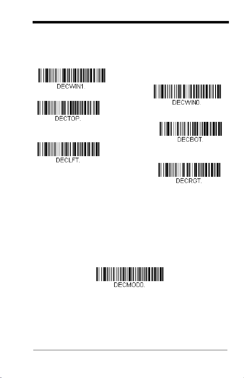
Scan
Left of Centering Window
Top of Centering Window
Right of Centering Window
Bottom of Centering Window
* Centering Off
Centering On
Full Omnidirectional
Centering On
bottom, left, or right of the centering window. Then scan the percent you want to
shift the centering window using digits on the inside back cover of this manual.
Save
Scan
Right.
.
, then scan one of the following bar codes to change the top,
Default Centering = 40% for Top and Left, 60% for Bottom and
Decode Search Mode
There are three selectable decode (scanning) modes:
Full Omnidirectional
of an image, and searches to the image’s limits. This mode reads all
symbologies (including OCR), in any orientation. The Full Omnidirectional
search is very thorough which may slow performance time.
Note: This search mode is the default setting for the 2D OEM Engines.
- Searches for bar code features beginning at the center
4 - 17
Page 46

Quick Omnidirectional
Quick Omnidirectional
Advanced Linear Decoding
around the center region of an image. This mode quickly reads all symbologies
in any orientation. The Quick Omnidirectional mode may miss some off-center
symbols, as well as larger Data Matrix and QR Code symbols.
- This is an abbreviated search for bar code features
Advanced Linear Decoding
band of the image. This mode is
and stacked bar codes. Advanced Linear Decoding cannot read 2D, OCR, or
Postal symbols.
- Performs quick horizontal linear scans in a center
not
omnidirectional, but does quickly read linear
Note: This search mode is the default setting for the point-and-shoot PDF OEM
Engines.
4 - 18
Page 47

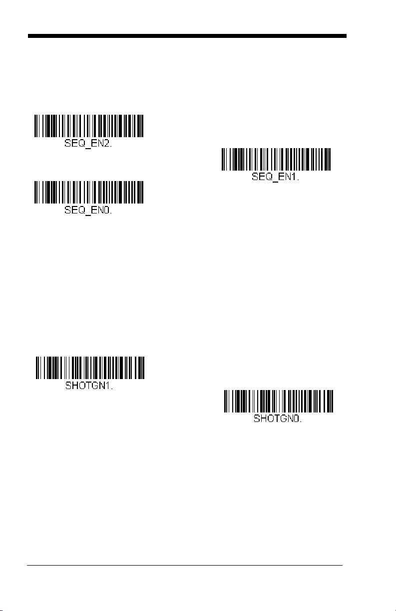
Output Sequence Overview
Require Output Sequence
When turned off, the bar code data will be output to the host as the Imager
decodes it. When turned on, all output data must conform to an edited sequence
or the Imager will not transmit the output data to the host device.
Note: This selection is unavailable when the Multiple Symbols Selection is
turned on.
Output Sequence Editor
This programming selection allows you to program the Imager to output data
(when scanning more than one symbol) in whatever order your application
requires, regardless of the order in which the bar codes are scanned. Reading
Default Sequence
the
shown below. These are the defaults. Be certain you want to delete or clear all
formats before you read the
Note: To make Output Sequence Editor selections, you’ll need to know the code
I.D., code length, and character match(es) your application requires. Use
the Alphanumeric symbols (inside back cover) to read these options.
Note: You must hold the trigger while reading each bar code in the sequence.
To Add an Output Sequence
symbol programs the Imager to the Universal values,
Default Sequence
symbol.
1. Scan the
21).
2. Code I.D.
On the Symbology Chart on page A-1, find the symbology to which you want
to apply the output sequence format. Locate the Hex value for that symbology and scan the 2 digit hex value from the Programming Chart (inside back
cover).
3. Length
Specify what length (up to 9999 characters) of data output will be acceptable
for this symbology. Scan the four digit data length from the Programming
Chart. (Note: 50 characters is entered as 0050. 9999 is a universal number, indicating all lengths.) When calculating the length, you must count any
programmed prefixes, suffixes, or formatted characters as part of the length
(unless using 9999).
4. Character Match Sequences
On the ASCII Conversion Chart (Code Page 1252), page A-3, find the Hex
value that represents the character(s) you want to match. Use the Programming Chart to read the alphanumeric combination that represents the ASCII
characters. (99 is the Universal number, indicating all characters.)
5. End Output Sequence Editor
Scan
to save your entries.
Enter Sequence
F F
to enter an Output Sequence for an additional symbology, or
symbol (see Require Output Sequence, page 4-
Save
4 - 19
Page 48

Other Programming Selections
A - Code 39
B - Code 128
C - Code 93
•
Discard
This exits without saving any Output Sequence changes.
Output Sequence Example
In this example, you are scanning Code 93, Code 128, and Code 39 bar codes,
but you want the imager to output Code 39 1st, Code 128 2nd, and Code 93 3rd,
as shown below.
Note: Code 93 must be enabled to use this example.
You would set up the sequence editor with the following command line:
SEQBLK62999941FF6A999942FF69999943FF
The breakdown of the command line is shown below:
SEQBLK sequence editor start command
62 code identifier for Code 39
9999 code length that must match for Code 39, 9999 = all lengths
41 start character match for Code 39, 41h = “A”
FF termination string for first code
6A code identifier for Code 128
9999 code length that must match for Code 128, 9999 = all lengths
42 start character match for Code 128, 42h = “B”
FF termination string for second code
69 code identifier for Code 93
4 - 20
Page 49

9999 code length that must match for Code 93, 9999 = all lengths
Enter Sequence
Default Sequence
43 start character match for Code 93, 43h = “C”
FF termination string for third code
To program the previous example using specific lengths, you would have to
count any programmed prefixes, suffixes, or formatted characters as part of the
length. If you use the example on page 4-20, but assume a <CR> suffix and
specific code lengths, you would use the following command line:
SEQBLK62001241FF6A001342FF69001243FF
The breakdown of the command line is shown below:
SEQBLK sequence editor start command
62 code identifier for Code 39
0012 A - Code 39 sample length (11) plus CR suffix (1) = 12
41 start character match for Code 39, 41h = “A”
FF termination string for first code
6A code identifier for Code 128
0013 B - Code 128 sample length (12) plus CR suffix (1) = 13
42 start character match for Code 128, 42h = “B”
FF termination string for second code
69 code identifier for Code 93
0012 C - Code 93 sample length (11) plus CR suffix (1) = 12
43 start character match for Code 93, 43h = “C”
FF termination string for third code
Output Sequence Editor
Require Output Sequence
When an output sequence is
sequence or the imager will not transmit the output data to the host device.
When it’s
conform to an edited sequence, but if it cannot, the imager transmits all output
data to the host device as is.
On/Not Required
Required
, the imager will attempt to get the output data to
, all output data must conform to an edited
4 - 21
Page 50
When the output sequence is
Required
On/Not Required
*Off
On
* Off
imager decodes it.
Note: This selection is unavailable when the Multiple Symbols Selection is
turned on.
Off
, the bar code data is output to the host as the
Multiple Symbols
Note: This feature does not work when the Imager is in Low Power mode.
When this programming selection is turned On, it allows you to read multiple
symbols when the trigger is activated. If you press and hold the trigger, aiming
the Imager at a series of symbols, it reads unique symbols once, beeping (if
turned on) for each read. The imager attempts to find and decode new symbols
as long as the trigger is activated. When this programming selection is turned
Off
, the Imager will only read the symbol closest to the aiming beam.
4 - 22
Page 51

No Read
On
* Off
With No Read turned On, the Imager notifies you if a code cannot be read. If
using a Quick*View Scan Data Window, an “NR” appears when a code cannot
be read. If No Read is turned
If you want a different notation than “NR,” for example, “Error,” or “Bad Code,”
you can edit the output message using the Data Formatter (page 6-5). The hex
code for the No Read symbol is 9C.
Off
, the “NR” will not appear.
4 - 23
Page 52

Print Weight
Set Print Weight
* Default
On
* Off
VIDREV0.
Print Weight is used to adjust the way the imager reads Matrix symbols. If a
imager will be seeing consistently heavily printed matrix symbols, then a print
weight of 6 may improve the reading performance. For consistently light printing,
a print weight of 2 may help. After scanning the
the print weight (from 1-7) by scanning digits from the inside back cover, then
scanning
Save
.
Default = 4
.
Set Print Weight
bar code, set
Video Reverse
Video Reverse is used to allow the imager to read bar codes that are inverted.
The “Off” bar code below is an example of this type of bar code. If additional
menuing is required, Video Reverse must be disabled to read the menu bar
codes and then re-enabled after menuing is completed.
Note: Images downloaded from the unit will not be reversed. This is a setting
for decoding only.
4 - 24
Page 53

Working Orientation
Upright:
Rotate Clockwise 90°:
Upside Down:
Rotate
Counterclockwise 90°:
* Upright
Rotate Clockwise 90°
Upside Down
Rotate Counterclockwise 90°
Some bar codes are direction-sensitive. For example, Kix codes and OCR can
misread when scanned sideways or upside down. Use the working orientation
settings if your direction-sensitive codes will not usually be presented upright to
the scanner.
Default = Upright.
4 - 25
Page 54

4 - 26
Page 55

5
Data Editing
Prefix/Suffix Overview
When a bar code is scanned, additional information is sent to the host computer
along with the bar code data. This group of bar code data and additional,
user-defined data is called a “message string.” The selections in this section are
used to build the user-defined data into the message string.
Prefix and Suffix characters are data characters that can be sent before and after
scanned data. You can specify if they should be sent with all symbologies, or
only with specific symbologies. The following illustration shows the breakdown
of a message string:
Prefix
alpha numeric
characters
Scanned Data
variable length1-11
Suffix
1-11
alpha numeric
characters
Points to Keep In Mind
• It is not necessary to build a message string. The selections in this chapter
are only used if you wish to alter the default settings.
Default suffix = None
• A prefix or suffix may be added or cleared from one symbology or all
symbologies.
• You can add any prefix or suffix from the ASCII Conversion Chart (Code Page
1252), page A-3, plus Code I.D. and AIM I.D.
• You can string together several entries for several symbologies at one time.
• Enter prefixes and suffixes in the order in which you want them to appear on
the output.
• When Setting up for specific symbologies, instead of All Symbologies, the
symbology ID value counts as an added prefix or suffix character.
.
Default prefix = None.
5 - 1
Page 56

To Add a Prefix or Suffix:
Step 1. Scan the Add Prefix or Add Suffix symbol (page 5-4).
Step 2. Determine the 2 digit Hex value from the Symbology Chart (included in
Appendix A) for the symbology to which you want to apply the prefix or
suffix. For example, for Code 128, Code ID is “j” and Hex ID is “6A”.
Step 3. Scan the 2 hex digits from the Programming Chart inside the back
cover of this manual or scan 9, 9 for all symbologies.
Step 4. Determine the hex value from the ASCII Conversion Chart (Code
Page 1252), page A-3, for the prefix or suffix you wish to enter.
Step 5. Scan the 2 digit hex value from the Programming Chart inside the back
cover of this manual.
Step 6. Repeat Steps 4 and 5 for every prefix or suffix character.
Step 7. To add the Code I.D., scan 5, C, 8, 0.
To add AIM I.D., scan 5, C, 8, 1.
To add a backslash (\), scan 5, C, 5, C.
Note: To add a backslash (\) as in Step 7, you must scan 5C twice – once to
create the leading backslash and then to create the backslash itself.
Step 8. Scan Save to exit and save, or scan Discard to exit without saving.
Repeat Steps 1-6 to add a prefix or suffix for another symbology.
Example: Add a Suffix to a specific symbology
To send a CR (carriage return)Suffix for UPC only:
Step 1. Scan Add Suffix.
Step 2. Determine the 2 digit hex value from the Symbology Chart (included in
Appendix A) for UPC.
Step 3. Scan 6, 3 from the Programming Chart inside the back cover of this
manual.
Step 4. Determine the hex value from the ASCII Conversion Chart (Code
Page 1252), page A-3, for the CR (carriage return).
Step 5. Scan 0, D from the Programming Chart inside the back cover of this
manual.
Step 6. Scan Save, or scan Discard to exit without saving.
5 - 2
Page 57

To Clear One or All Prefixes or Suffixes:
Add CR Suffix
All Symbologies
You can clear a single prefix or suffix, or clear all prefixes/suffixes for a
symbology. When you Clear One Prefix (Suffix), the specific character you
select is deleted from the symbology you want. When you Clear All Prefixes
(Suffixes), all the prefixes or suffixes for a symbology are deleted.
Step 1. Scan the Clear One Prefix or Clear One Suffix symbol.
Step 2. Determine the 2 digit Hex value from the Symbology Chart (included in
Appendix A) for the symbology from which you want to clear the prefix
or suffix.
Step 3. Scan the 2 digit hex value from the Programming Chart inside the back
cover of this manual or scan 9, 9 for all symbologies.
Your change is automatically saved.
To Add a Carriage Return Suffix to All Symbologies
Scan the following bar code if you wish to add a carriage return suffix to all
symbologies at once. This action first clears all current suffixes, then programs
a carriage return suffix for all symbologies.
5 - 3
Page 58

Prefix Selections
Add Prefix
Clear One Prefix
Clear All Prefixes
Add Suffix
Clear One Suffix
Clear All Suffixes
* Enable
Disable
Suffix Selections
Function Code Transmit
When this selection is enabled and function codes are contained within the
scanned data, the imager transmits the function code to the terminal.
Enable.
5 - 4
Default =
Page 59

Intercharacter, Interfunction, and Intermessage
1 2345
Intercharacter Delay
Prefix Scanned Data Suffix
Intercharacter Delay
Delays
Some terminals drop information (characters) if data comes through too quickly.
Intercharacter, interfunction, and intermessage delays slow the transmission of
data, increasing data integrity.
Each delay is composed of a 5 millisecond step. You can program up to 99 steps
(of 5 ms each) for a range of 0-495 ms.
Intercharacter Delay
An intercharacter delay of up to 495 milliseconds may be placed between the
transmission of each character of scanned data. Scan the Intercharacter Delay
bar code below, then scan the number of milliseconds and the SAVE bar code
using the Programming Chart inside the back cover of this manual.
To remove this delay, scan the Intercharacter Delay bar code, then set the
number of steps to 0. Scan the SAVE bar code using the Programming Chart
inside the back cover of this manual.
Note: Intercharacter delays are not supported in USB serial emulation.
5 - 5
Page 60

User Specified Intercharacter Delay
Delay Length
Character to Trigger Delay
Interfunction Delays
Prefix Scanned Data Suffix
1 2345STX HT CR LF
Interfunction Delay
An intercharacter delay of up to 495 milliseconds may be placed after the
transmission of a particular character of scanned data. Scan the Delay Length
bar code below, then scan the number of milliseconds and the SAVE bar code
using the Programming Chart inside the back cover of this manual.
Next, scan the Character to Trigger Delay bar code, then the 2-digit hex value
for the ASCII character that will trigger the delay ASCII Conversion Chart (Code
Page 1252), page A-3.
To remove this delay, scan the Delay Length bar code, and set the number of
steps to 0. Scan the SAVE bar code using the Programming Chart inside the
back cover of this manual.
Interfunction Delay
An interfunction delay of up to 495 milliseconds may be placed between the
transmission of each segment of the message string. Scan the Interfunction
Delay bar code below, then scan the number of milliseconds and the SAVE bar
code using the Programming Chart inside the back cover of this manual.
To remove this delay, scan the Interfunction Delay bar code, then set the
number of steps to 0. Scan the SAVE bar code using the Programming Chart
inside the back cover of this manual.
5 - 6
Page 61

Intermessage Delay
2nd Scan Transmission1st Scan Transmission
Intermessage Delay
Intermessage Delay
An intermessage delay of up to 495 milliseconds may be placed between each
scan transmission. Scan the Intermessage Delay bar code below, then scan
the number of milliseconds and the SAVE bar code using the Programming
Chart inside the back cover of this manual.
To remove this delay, scan the Intermessage Delay bar code, then set the
number of steps to 0. Scan the SAVE bar code using the Programming Chart
inside the back cover of this manual.
5 - 7
Page 62

5 - 8
Page 63

6
Data Formatting
Data Format Editor Introduction
You may use the Data Format Editor to change the imager’s output. For
example, you can use the Data Format Editor to insert characters at certain
points in bar code data as it is scanned. The selections in the following pages
are used only if you wish to alter the output.
Normally, when you scan a bar code, it gets outputted automatically; however
when you do a format, you must use a “send” command (see Send Commands
on page 6-2) within the format program to output data.
Multiple formats may be programmed into the imager. They are stacked in the
order in which they are entered. However, the following list presents the order
in which formats are applied:
1. Specific Term ID, Actual Code ID, Actual Length
2. Specific Term ID, Actual Code ID, Universal Length
3. Specific Term ID, Universal Code ID, Actual Length
4. Specific Term ID, Universal Code ID, Universal Length
5. Universal Term ID, Actual Code ID, Actual Length
6. Universal Term ID, Actual Code ID, Universal Length
7. Universal Term ID, Universal Code ID, Actual Length
8. Universal Term ID, Universal Code ID, Universal Length
Default Data Format setting = None.
If you have changed data format settings, and wish to clear all formats and return
to the factory defaults, scan the Default Data Format code on page 6-4.
To Add a Data Format
Step 1. Scan the Enter Data Format symbol (page 6-4).
Step 2. Primary/Alternate Format
Determine if this will be your primary data format, or one of 3 alternate
formats. (Alternate formats allow you “single shot” capability to scan
one bar code using a different data format. After the one bar code has
been read, the imager reverts to the primary data format. See page 6-
5.) If you are programming the primary format, scan 0 using the
Programming Chart inside the back cover of this manual. If you are
programming an alternate format, scan 1, 2, or 3, depending on the
alternate format you are programming.
Step 3. Terminal Type
Refer to Supported Terminals (page 3-1) and locate the Terminal ID
number for your PC. Scan three numeric bar codes on the inside back
6 - 1
Page 64

cover to program the imager for your terminal ID (you must enter 3 digits). For example, scan 0 0 0 for RS-232.
Note: The wildcard for all terminal types is 099.
Step 4. Code I.D.
In Appendix A, find the symbology to which you want to apply the data
format. Locate the Hex value for that symbology and scan the 2 digit
hex value from the Programming Chart inside the back cover of this
manual.
Step 5. Length
Specify what length (up to 9999 characters) of data will be acceptable
for this symbology. Scan the four digit data length from the
Programming Chart inside the back cover of this manual. (Note: 50
characters is entered as 0050. 9999 is a universal number, indicating
all lengths.)
Step 6. Editor Commands
Refer to Data Format Editor Commands (page 6-2). Scan the symbols
that represent the command you want to enter. 94 alphanumeric characters may be entered for each symbology data format.
Step 7. Scan Save from the Programming Chart inside the back cover of this
manual to save your entries.
Other Programming Selections
• Clear One Data Format
This deletes one data format for one symbology. If you are clearing the
primary format, scan 0 from the Programming Chart inside the back cover of
this manual. If you are clearing an alternate format, scan 1, 2, or 3, depending
on the alternate format you are clearing. Scan the Terminal Type and Code
I.D. (see Supported Terminals on page 3-1), and the bar code data length for
the specific data format that you want to delete. All other formats remain
unaffected.
• Save from the Programming Chart inside the back cover of this manual
This exits, saving any Data Format changes.
• Discard from the Programming Chart inside the back cover of this manual
This exits without saving any Data Format changes.
Data Format Editor Commands
Send Commands
F1 Send all characters followed by “xx” key or function code, starting from cur-
rent cursor position.
ASCII code, see ASCII Conversion Chart (Code Page 1252), page A-3.)
F2 Send “nn” characters followed by “xx” key or function code, starting from
current cursor position.
Syntax = F1xx
Syntax = F2nnxx
(xx stands for the hex value for an
(nn stands for the numeric value
6 - 2
Page 65

(00-99) for the number of characters and xx stands for the hex value for an
ASCII code. See ASCII Conversion Chart (Code Page 1252), page A-3.)
F3 Send up to but not including “ss” character (Search and Send) starting from
current cursor position, leaving cursor pointing to “ss” character followed by
“xx” key or function code.
hex values for ASCII codes, see ASCII Conversion Chart (Code Page
1252), page A-3.)
F4 Send “xx” character “nn” times (Insert) leaving cursor in current cursor posi-
E9 Send all but the last “nn” characters, starting from the current cursor posi-
Syntax = F4xxnn
tion.
ASCII Conversion Chart (Code Page 1252), page A-3, and nn is the
numeric value (00-99) for the number of times it should be sent.)
Syntax = E9nn
tion.
characters that will not be sent at the end of the message.)
Syntax = F3ssxx
(xx stands for the hex value for an ASCII code, see
(nn is the numeric value (00-99) for the number of
(ss and xx both stand for the
Move Commands
F5 Move the cursor ahead “nn” characters from current cursor position.
Syntax = F5nn
characters the cursor should be moved ahead.)
F6 Move the cursor back “nn” characters from current cursor position.
Syntax = F6nn
characters the cursor should be moved back.)
F7 Move the cursor to the beginning of the data string.
EA Move the cursor to the end of the data string.
(nn stands for the numeric value (00-99) for the number of
(nn stands for the numeric value (00-99) for the number of
Syntax = F7.
Syntax = EA
Search Commands
F8 Search ahead for “xx” character from current cursor position, leaving cursor
pointing to “xx” character.
an ASCII code, see see ASCII Conversion Chart (Code Page 1252), page
A-3.)
F9 Search back for “xx” character from current cursor position, leaving cursor
pointing to “xx” character.
an ASCII code, see see ASCII Conversion Chart (Code Page 1252), page
A-3.)
E6 Search ahead for the first non “xx” character from the current cursor posi-
tion, leaving cursor pointing to non “xx” character.
stands for the hex value for an ASCII code, see ASCII Conversion Chart
(Code Page 1252), page A-3.
E7 Search back for the first non “xx” character from the current cursor position,
leaving cursor pointing to non “xx” character.
the hex value for an ASCII code, see ASCII Conversion Chart (Code Page
1252), page A-3.)
Syntax = F8xx
Syntax = F9xx
(xx stands for the hex value for
(xx stands for the hex value for
Syntax = E6xx
Syntax = E7xx
(xx
(xx stands for
Miscellaneous Commands
FB Suppress all occurrences of up to 15 different characters, starting at the
current cursor position, as the cursor is advanced by other commands.
When the FC command is encountered, the suppress function is termi-
nated. The cursor is not moved by the FB command. Syntax = FBnnxxyy
. .zz where nn is a count of the number of suppressed characters in the list
6 - 3
Page 66

and xxyy .. zz is the list of characters to be suppressed. (xx stands for the
Enter Data Format
* Default Data Format
Clear One Data Format
Save
Discard
Clear All Data Formats
hex value for an ASCII code, see ASCII Conversion Chart (Code Page
1252), page A-3.)
FC Disables suppress filter and clear all suppressed characters.
Syntax = FC.
E4 Replaces up to 15 characters in the data string with user specified charac-
ters. Replacement continues until the E5 command is encountered.
tax = E4nnxx
1xx2yy1yy2
...zz1zz
characters to be replaced plus replacement characters; xx
ters to be replaced and xx
through zz
and zz2.
1
2
E5 Terminates character replacement.
where nn is the total count of both
2
1
defines replacement characters, continuing
Syntax = E5.
defines charac-
Syn-
FE Compare character in current cursor position to the character “xx.” If char-
acters are equal, increment cursor. If characters are not equal, no format
match.
Syntax = FExx
(xx stands for the hex value for an ASCII code, see
ASCII Conversion Chart (Code Page 1252), page A-3.)
EC Check to make sure there is an ASCII number at the current cursor posi-
tion. If character is not numeric, format is aborted.
Syntax = EC
.
ED Check to make sure there is a non-numeric ASCII character at the current
cursor position. If character is numeric, format is aborted.
Syntax = ED
.
Data Format Editor
6 - 4
Page 67
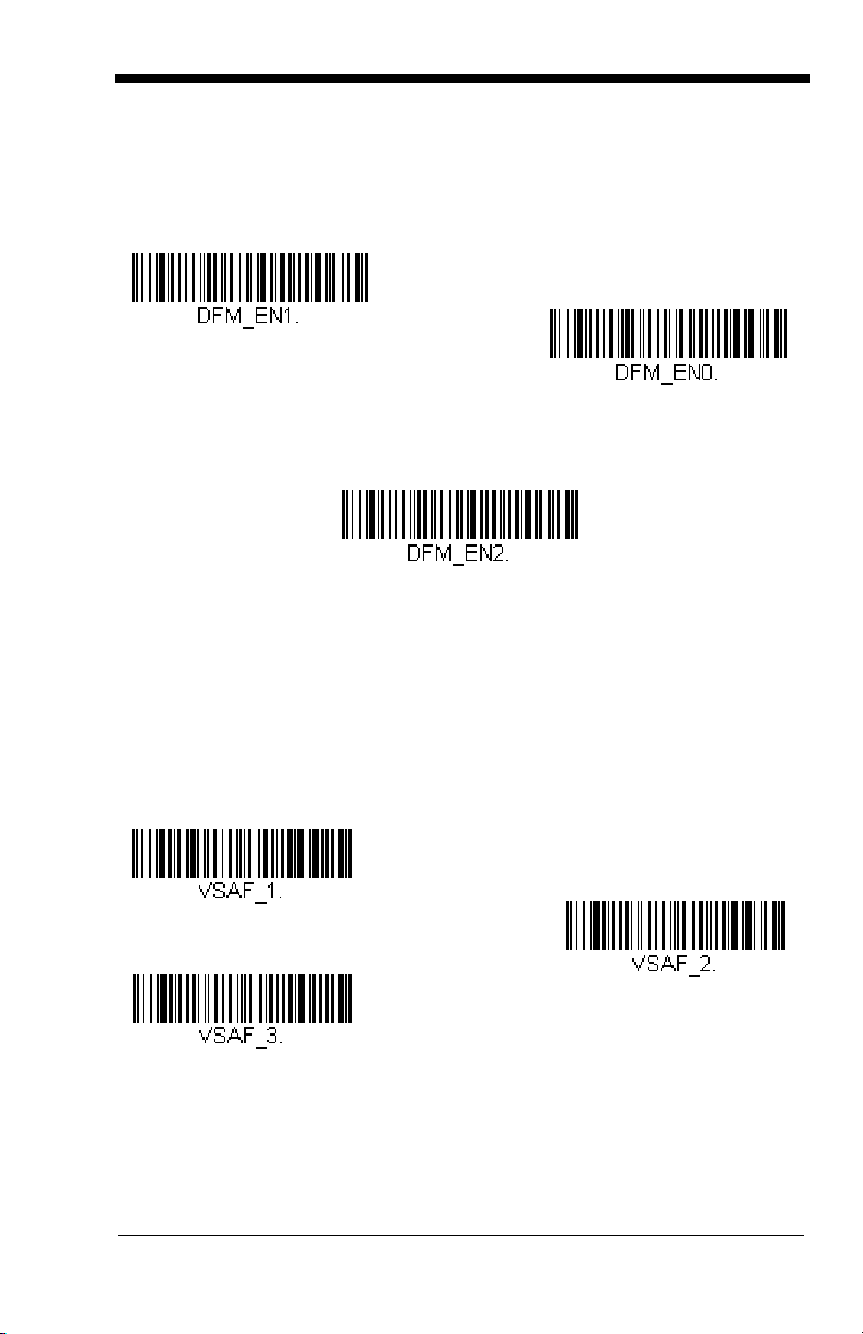
Data Formatter
Data Formatter Off
* Data Formatter On,
but Not Required
Data Format On, Format Required
Alternate Data Format 1
Alternate Data Format 2
Alternate Data Format 3
When Data Formatter is turned off, the bar code data is output to the host as read
(including prefixes and suffixes). Choose one of the following options.
Default
= Data Formatter On, but Not Required.
When Data Formatter is required, all input data must conform to an edited format
or the imager does not transmit the input data to the host device.
Alternate Data Formats
Alternate formats allow you “single shot” capability to scan one bar code using a
different data format than your primary format. When data formats are
programmed (see page 6-1), you must input whether you are programming the
primary format, or an alternate format numbered 1, 2, or 3.
An alternate format is initiated by scanning one of the 3 alternate format bar
codes below. The imager will scan the next bar code, formatting the data with
the selected alternate format, then revert immediately to the primary format.
6 - 5
Page 68

6 - 6
Page 69

7
Symbologies
This programming section contains the following menu selections. Refer to
Chapter 11 for settings and defaults.
• All Symbologies • Japanese Post
• Australian Post
• Aztec Code • Korea Post
• British Post • Matrix 2 of 5
• Canadian Post • MaxiCode
• China Post • MicroPDF417
• Codabar • MSI
• Codablock F • PDF417
• Code 11 • Planet Code
• Code 128 • Plessey Code
• Code 16K • PosiCode A and B
• Straight 2 of 5 Industrial • Postnet
• Code 39 • QR Code
• Code 49 • RSS Expanded
• Code 93 • RSS Limited
• Data Matrix • RSS-14
• EAN/JAN-13
• EAN/JAN-8 • Telepen
• EAN•UCC Composite Codes • UPC-A
• Straight 2 of 5 IATA
• Interleaved 2 of 5
• Kix (Netherlands)
Post
• TCIF Linked Code 39
(TLC39)
• UPC-A/EAN-13 with
Extended Coupon
Code
7 - 1
Page 70

All Symbologies
All Symbologies On
All Symbologies Off
If you want to decode all the symbologies allowable for your imager, scan the
Symbologies On
particular symbology, scan All Symbologies Off followed by the On symbol for
that particular symbology.
code. If on the other hand, you want to decode only a
All
Message Length Description
You are able to set the valid reading length of some of the bar code symbologies.
If the data length of the scanned bar code doesn’t match the valid reading length,
the imager will issue an error beep. You may wish to set the same value for
minimum and maximum length to force the imager to read fixed length bar code
data. This helps reduce the chances of a misread.
EXAMPLE: Decode only those bar codes with a count of 9-20 characters.
EXAMPLE: Decode only those bar codes with a count of 15 characters.
For a value other than the minimum and maximum message length defaults,
scan the bar codes included in the explanation of the symbology, then scan the
digit value of the message length and Save bar codes on the Programming Chart
inside the back cover of this manual. The minimum and maximum lengths and
the defaults are included with the respective symbologies.
Min. length = 09 Max. length = 20
Min. length = 15 Max. length = 15
7 - 2
Page 71
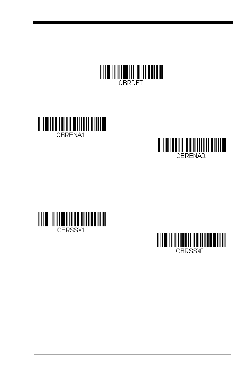
Codabar
* On
Off
Transmit
* Don’t Transmit
<Default All Codabar Settings>
Codabar
Codabar Start/Stop Characters
Start/Stop characters identify the leading and trailing ends of the bar code. You
may either transmit, or not transmit Start/Stop characters.
Default = Don’t Transmit
.
Codabar Check Character
Codabar check characters are created using different “modulos.” You can
program the imager to read only Codabar bar codes with Modulo 16 check
characters.
No Check Character
data with or without a check character.
When Check Character is set to
read Codabar bar codes printed with a check character, and will transmit this
character at the end of the scanned data.
Default = No Check Character.
indicates that the imager reads and transmits bar code
Validate and Transmit
, the imager will only
7 - 3
Page 72

When Check Character is set to
* No Check Character
Validate Modulo 16
and Transmit
Validate Modulo 16, but
Don’t Transmit
A12D D34A
Codabar
Character
Stop Start StopStart
* On
Off
Require
read Codabar bar codes printed
Validate, but Don’t Transmit
with
a check character, but will not transmit the
, the unit will only
check character with the scanned data.
Codabar Concatenation
Codabar supports symbol concatenation. When you enable concatenation, the
imager looks for a Codabar symbol having a “D” start character, adjacent to a
symbol having a “D” stop character. In this case the two messages are
concatenated into one with the “D” characters omitted.
Default = On.
Select Require to prevent the imager from decoding a single “D” Codabar
symbol without its companion. This selection has no effect on Codabar symbols
without Stop/Start D characters.
7 - 4
Page 73

Codabar Message Length
Minimum Message Length
Maximum Message Length
Scan the bar codes below to change the message length. Refer to Message
Length Description (page 7-2) for additional information. Minimum and
Maximum lengths = 2-60. Minimum Default = 4, Maximum Default = 60.
7 - 5
Page 74

Code 39
* On
Off
Transmit
* Don’t Transmit
< Default All Code 39 Settings >
Code 39
Code 39 Start/Stop Characters
Start/Stop characters identify the leading and trailing ends of the bar code. You
may either transmit, or not transmit Start/Stop characters.
Transmit.
Default = Don’t
Code 39 Check Character
No Check Character indicates that the imager reads and transmits bar code
data with or without a check character.
7 - 6
Page 75
When Check Character is set to Validate, but Don’t Transmit, the unit only
Validate, but Don’t Transmit
* No Check Character
Validate and Transmit
Minimum Message Length
Maximum Message Length
reads Code 39 bar codes printed with a check character, but will not transmit the
check character with the scanned data.
When Check Character is set to Validate and Transmit, the imager only reads
Code 39 bar codes printed with a check character, and will transmit this
character at the end of the scanned data.
Default = No Check Character.
Code 39 Message Length
Scan the bar codes below to change the message length. Refer to Message
Length Description (page 7-2) for additional information. Minimum and
Maximum lengths = 0-48. Minimum Default = 0, Maximum Default = 48.
7 - 7
Page 76

Code 39 Append
* Off
On
* Off
On
This function allows the imager to append the data from several Code 39 bar
codes together before transmitting them to the host computer. When this
function is enabled, the imager stores those Code 39 bar codes that start with a
space (excluding the start and stop symbols), and does not immediately transmit
the data. The imager stores the data in the order in which the bar codes are
read, deleting the first space from each. The imager transmits the appended
data when it reads a Code 39 bar code that starts with a character other than a
space.
Default = Off.
Code 32 Pharmaceutical (PARAF)
Code 32 Pharmaceutical is a form of the Code 39 symbology used by Italian
pharmacies. This symbology is also known as PARAF.
Note: Trioptic Code (page 7-39) must be turned off while scanning Code 32
Pharmaceutical codes.
7 - 8
Page 77
Full ASCII
* Full ASCII Off
Full ASCII On
If Full ASCII Code 39 decoding is enabled, certain character pairs within the bar
code symbol will be interpreted as a single character. For example: $V will be
decoded as the ASCII character SYN, and /C will be decoded as the ASCII
character #.
Default = On
.
NUL %U DLE $P
SOH $A
STX $B
ETX $C
EOT $D
ENQ $E
ACK $F
BEL $G
BS $H
HT $I
LF $J
VT $K
FF $L
CR $M
SO $N
SI $O
DC1 $Q !/A 11AA QQa+Aq+Q
DC2 $R “/B 22BBRRb+Br+R
DC3 $S #/C 33CCSS c+Cs+S
DC4 $T $/D 44 DDTTd+Dt+T
NAK $U %/E 55EEUUe+Eu+U
SYN $V &/F 66 FFVVf+Fv+V
ETB $W ‘/G77GGWW g+Gw+W
CAN $X (/H 88HHXX h+Hx+X
EM $Y )/I 99 IIYYi+Iy+Y
SUB $Z */J :/ZJJZZ j+Jz+Z
ESC %A +/K ;%FKK[%Kk+K{%P
FS %B ,/L <%GLL\%Ll+L|%Q
GS %C -- =%HMM]%Mm+M}%R
RS %D .. >%INN^%Nn+N~%S
US %E //O?%JOO_%Oo+ODEL %T
SP SPACE
00@%VPP‘%Wp+P
Character pairs /M and /N decode as a minus sign and period respectively.
Character pairs /P through /Y decode as 0 through 9.
7 - 9
Page 78
Code 39 Code Page
Code 39 Code Page
* On
Off
Code pages define the mapping of character codes to characters. If the data
received does not display with the proper characters, it may be because the bar
code being scanned was created using a code page that is different from the
one the host program is expecting. If this is the case, scan the bar code below,
select the code page with which the bar codes were created (see Code Page
Mapping of Printed Bar Codes on page A-5), and scan the value and the Save
bar code from the Programming Chart on the inside the back cover of this
manual. The data characters should then appear properly.
Interleaved 2 of 5
< Default All Interleaved 2 of 5 Settings >
Interleaved 2 of 5
Check Digit
No Check Digit indicates that the imager reads and transmits bar code data with
or without a check digit.
When Check Digit is set to Validate, but Don’t Transmit, the unit only reads
Interleaved 2 of 5 bar codes printed with a check digit, but will not transmit the
check digit with the scanned data.
7 - 10
Page 79
When Check Digit is set to Validate and Transmit, the imager only reads
Validate, but Don’t Transmit
* No Check Digit
Validate and Transmit
Minimum Message Length
Maximum Message Length
Interleaved 2 of 5 bar codes printed with a check digit, and will transmit this digit
at the end of the scanned data.
Default = No Check Digit.
Interleaved 2 of 5 Message Length
Scan the bar codes below to change the message length. Refer to Message
Length Description (page 7-2) for additional information. Minimum and
Maximum lengths = 2-80. Minimum Default = 4, Maximum Default = 80.
7 - 11
Page 80

Code 93
* On
Off
Minimum Message Length
Maximum Message Length
< Default All Code 93 Settings >
Code 93
Code 93 Message Length
Scan the bar codes below to change the message length. Refer to Message
Length Description (page 7-2) for additional information. Minimum and
Maximum lengths = 0-80. Minimum Default = 0, Maximum Default = 80.
7 - 12
Page 81

Code 93 Code Page
Code 93 Code Page
Code pages define the mapping of character codes to characters. If the data
received does not display with the proper characters, it may be because the bar
code being scanned was created using a code page that is different from the
one the host program is expecting. If this is the case, scan the bar code below,
select the code page with which the bar codes were created (see Code Page
Mapping of Printed Bar Codes on page A-5), and scan the value and the Save
bar code from the Programming Chart on the inside the back cover of this
manual. The data characters should then appear properly.
7 - 13
Page 82

Straight 2 of 5 Industrial (three-bar start/stop)
On
* Off
Minimum Message Length
Maximum Message Length
<Default All Straight 2 of 5 Industrial Settings>
Straight 2 of 5 Industrial
Straight 2 of 5 Industrial Message Length
Scan the bar codes below to change the message length. Refer to Message
Length Description (page 7-2) for additional information. Minimum and
Maximum lengths = 1-48. Minimum Default = 4, Maximum Default = 48.
7 - 14
Page 83

Straight 2 of 5 IATA (two-bar start/stop)
On
* Off
Minimum Message Length
Maximum Message Length
<Default All Straight 2 of 5 IATA Settings>
Straight 2 of 5 IATA
Straight 2 of 5 IATA Message Length
Scan the bar codes below to change the message length. Refer to Message
Length Description (page 7-2) for additional information. Minimum and
Maximum lengths = 1-48. Minimum Default = 4, Maximum Default = 48.
7 - 15
Page 84

Matrix 2 of 5
On
* Off
Minimum Message Length
Maximum Message Length
<Default All Matrix 2 of 5 Settings>
Matrix 2 of 5
Matrix 2 of 5 Message Length
Scan the bar codes below to change the message length. Refer to Message
Length Description (page 7-2) for additional information. Minimum and
Maximum lengths = 1-80. Minimum Default = 4, Maximum Default = 80.
7 - 16
Page 85
Code 11
On
* Off
One Check Digit
* Two Check Digits
<Default All Code 11 Settings>
Code 11
Check Digits Required
This option sets whether 1 or 2 check digits are required with Code 11 bar codes.
Default = Two Check Digits.
7 - 17
Page 86

Code 11 Message Length
Minimum Message Length
Maximum Message Length
Scan the bar codes below to change the message length. Refer to Message
Length Description (page 7-2) for additional information. Minimum and
Maximum lengths = 1-80. Minimum Default = 4, Maximum Default = 80.
7 - 18
Page 87

Code 128
* On
Off
* Off
On
<Default All Code 128 Settings>
Code 128
ISBT 128 Concatenation
In 1994 the International Society of Blood Transfusion (ISBT) ratified a standard
for communicating critical blood information in a uniform manner. The use of
ISBT formats requires a paid license. The ISBT 128 Application Specification
describes 1) the critical data elements for labeling blood products, 2) the current
recommendation to use Code 128 due to its high degree of security and its
space-efficient design, 3) a variation of Code 128 that supports concatenation of
neighboring symbols, and 4) the standard layout for bar codes on a blood
product label. Use the bar codes below to turn concatenation on or off.
=Off.
Default
7 - 19
Page 88

Code 128 Message Length
Minimum Message Length
Maximum Message Length
Code 128 Code Page
Scan the bar codes below to change the message length. Refer to Message
Length Description (page 7-2) for additional information. Minimum and
Maximum lengths = 0-80. Minimum Default = 0, Maximum Default = 80.
Code 128 Code Page
Code pages define the mapping of character codes to characters. If the data
received does not display with the proper characters, it may be because the bar
code being scanned was created using a code page that is different from the
one the host program is expecting. If this is the case, scan the bar code below,
select the code page with which the bar codes were created (see Code Page
Mapping of Printed Bar Codes on page A-5), and scan the value and the Save
bar code from the Programming Chart on the inside the back cover of this
manual. The data characters should then appear properly.
Default = 2.
Telepen
7 - 20
<Default All Telepen Settings>
Page 89
Telepen
On
* Off
Original Telepen Output
* AIM Telepen Output
Minimum Message Length
Maximum Message Length
Telepen Output
Using AIM Telepen Output, the imager reads symbols with start/stop pattern 1
and decodes them as standard full ASCII (start/stop pattern 1). When Original
Telepen Output is selected, the imager reads symbols with start/stop pattern 1
and decodes them as compressed numeric with optional full ASCII (start/stop
pattern 2).
Telepen Message Length
Scan the bar codes below to change the message length. Refer to Message
Length Description (page 7-2) for additional information. Minimum and
Maximum lengths = 1-60. Minimum Default = 1, Maximum Default = 60.
Default = AIM Telepen Output.
7 - 21
Page 90

UPC-A
* On
Off
* On
Off
<Default All UPC-A Settings>
UPC-A
UPC-A Check Digit
This selection allows you to specify whether the check digit should be
transmitted at the end of the scanned data or not.
Default = On
.
7 - 22
Page 91

UPC-A Number System
Off
* On
* 5 Digit Addenda Off
5 Digit Addenda On
* 2 Digit Addenda Off
2 Digit Addenda On
The numeric system digit of a U.P.C. symbol is normally transmitted at the
beginning of the scanned data, but the unit can be programmed so it will not
transmit it.
Default = On.
UPC-A Addenda
This selection adds 2 or 5 digits to the end of all scanned UPC-A data.
Default = Off for both 2 Digit and 5 Digit Addenda.
7 - 23
Page 92

UPC-A Addenda Required
* Not Required
Required
Off
* On
On
* Off
When
Required
have addenda. You must then turn on a 2 or 5 digit addenda listed on page 7-
Default = Not Required.
23.
is scanned, the imager will only read UPC-A bar codes that
UPC-A Addenda Separator
When this feature is on, there is a space between the data from the bar code and
the data from the addenda. When turned off, there is no space.
Default = On.
UPC-A/EAN-13 with Extended Coupon Code
Use the following codes to enable or disable UPC-A and EAN-13 with Extended
Coupon Code.
7 - 24
Default = On.
Page 93
UPC-E0
* UPC-E0 On
UPC-E0 Off
* Off
On
<Default All UPC-E Settings>
UPC-E0
Most U.P.C. bar codes lead with the 0 number system. For these codes, use the
UPC-E0 selection. If you need to read codes that lead with the 1 number system,
use UPC-E1 (page 7-28).
UPC-E0 Expand
UPC-E Expand expands the UPC-E code to the 12 digit, UPC-A format.
Default = Off.
Default = On.
7 - 25
Page 94

UPC-E0 Addenda Required
* Not Required
Required
Off
* On
Off
* On
When Addenda Required is set to on, the imager will only read UPC-E bar codes
that have addenda.
Default = Not Required.
UPC-E0 Addenda Separator
When this feature is on, there is a space between the data from the bar code and
the data from the addenda. When turned off, there is no space.
Default = On.
UPC-E0 Check Digit
Check Digit specifies whether the check digit should be transmitted at the end of
the scanned data or not.
Default = On.
7 - 26
Page 95

UPC-E0 Number System
Off
* On
* 5 Digit Addenda Off
5 Digit Addenda On
* 2 Digit Addenda Off
2 Digit Addenda On
The numeric system digit of a U.P.C. symbol is normally transmitted at the
beginning of the scanned data, but the unit can be programmed so it will not
transmit it.
Default = On.
UPC-E0 Addenda
This selection adds 2 or 5 digits to the end of all scanned UPC-E data.
Default = Off for both 2 Digit and 5 Digit Addenda.
7 - 27
Page 96

UPC-E1
UPC-E1 On
* UPC-E1 Off
Most U.P.C. bar codes lead with the 0 number system. For these codes, use
UPC-E0 (page 7-25). If you need to read codes that lead with the 1 number
system, use the UPC-E1 selection.
Default = Off.
EAN/JAN-13
<Default All EAN/JAN Settings>
7 - 28
Page 97

EAN/JAN-13
* On
Off
Off
* On
* 5 Digit Addenda Off
5 Digit Addenda On
* 2 Digit Addenda Off
2 Digit Addenda On
EAN/JAN-13 Check Digit
This selection allows you to specify whether the check digit should be
transmitted at the end of the scanned data or not.
EAN/JAN-13 Addenda
This selection adds 2 or 5 digits to the end of all scanned EAN/JAN-13 data.
Default = Off for both 2 Digit and 5 Digit Addenda.
Default = On.
7 - 29
Page 98

EAN/JAN-13 Addenda Required
* Not Required
Required
Off
* On
* Off
On
When Addenda Required is set to on, the imager will only read EAN/JAN-13 bar
codes that have addenda.
Default = Not Required.
EAN/JAN-13 Addenda Separator
When this feature is on, there is a space between the data from the bar code and
the data from the addenda. When turned off, there is no space.
Default = On.
Note: If you want to enable or disable EAN13 with Extended Coupon Code,
refer to UPC-A/EAN-13 with Extended Coupon Code (page 7-24).
ISBN Translate
This selection causes EAN-13 Bookland symbols to be translated into their
equivalent ISBN number format.
7 - 30
Default = Off.
Page 99

EAN/JAN-8
* On
Off
Off
* On
<Default All EAN/JAN-8 Settings>
EAN/JAN-8
EAN/JAN-8 Check Digit
This selection allows you to specify whether the check digit should be
transmitted at the end of the scanned data or not.
Default = On.
7 - 31
Page 100

EAN/JAN-8 Addenda
* 5 Digit Addenda Off
5 Digit Addenda On
* 2 Digit Addenda Off
2 Digit Addenda On
* Not Required
Required
Off
* On
This selection adds 2 or 5 digits to the end of all scanned EAN/JAN-8 data.
Default = Off for both 2 Digit and 5 Digit Addenda.
EAN/JAN-8 Addenda Required
When Addenda Required is set to on, the imager will only read EAN/JAN-8 bar
codes that have addenda.
Default = Not Required.
EAN/JAN-8 Addenda Separator
When this feature is on, there is a space between the data from the bar code and
the data from the addenda. When turned off, there is no space.
Default = On.
7 - 32
 Loading...