

Page 1
32003532-005
Dual Auxiliary Switch Package
INSTALLATION INSTRUCTIONS
APPLICATION
The Dual Auxiliary Switch Package contains two
independent 360 degree rotary switch cams for use in
conjunction with Direct Coupled Actuators (DCA). See
Table 1. It provides an on/off signal at two adjustable
points in the actuator stroke. This signal can be routed to
a controller or used to control equipment external to the
actuator (for example, electric reheat coils and fan). As
the device mounts over the DCA hub and setscrews, it
can be added to an already-installed DCA.
IMPORTANT
1. The 32003532-005 housing is made of a material designed to survive UL555(S) Smoke and
Fire Damper/Actuator testing.
2. Switches are not designed to function at the
extreme temperatures of the UL555(S) test for
extended periods.
Table 1. Switch and Actuator Compatibility.
Compatible Direct Coupled Actuator Models
ML4105 ML4202 ML8105 MS4209
ML4115 ML4302 ML8115 MS4309
ML4125 ML4702 ML8125 MS4709
ML4135 ML4802 ML8135 MS4809
ML8202 MS8209
ML8302 MS8309
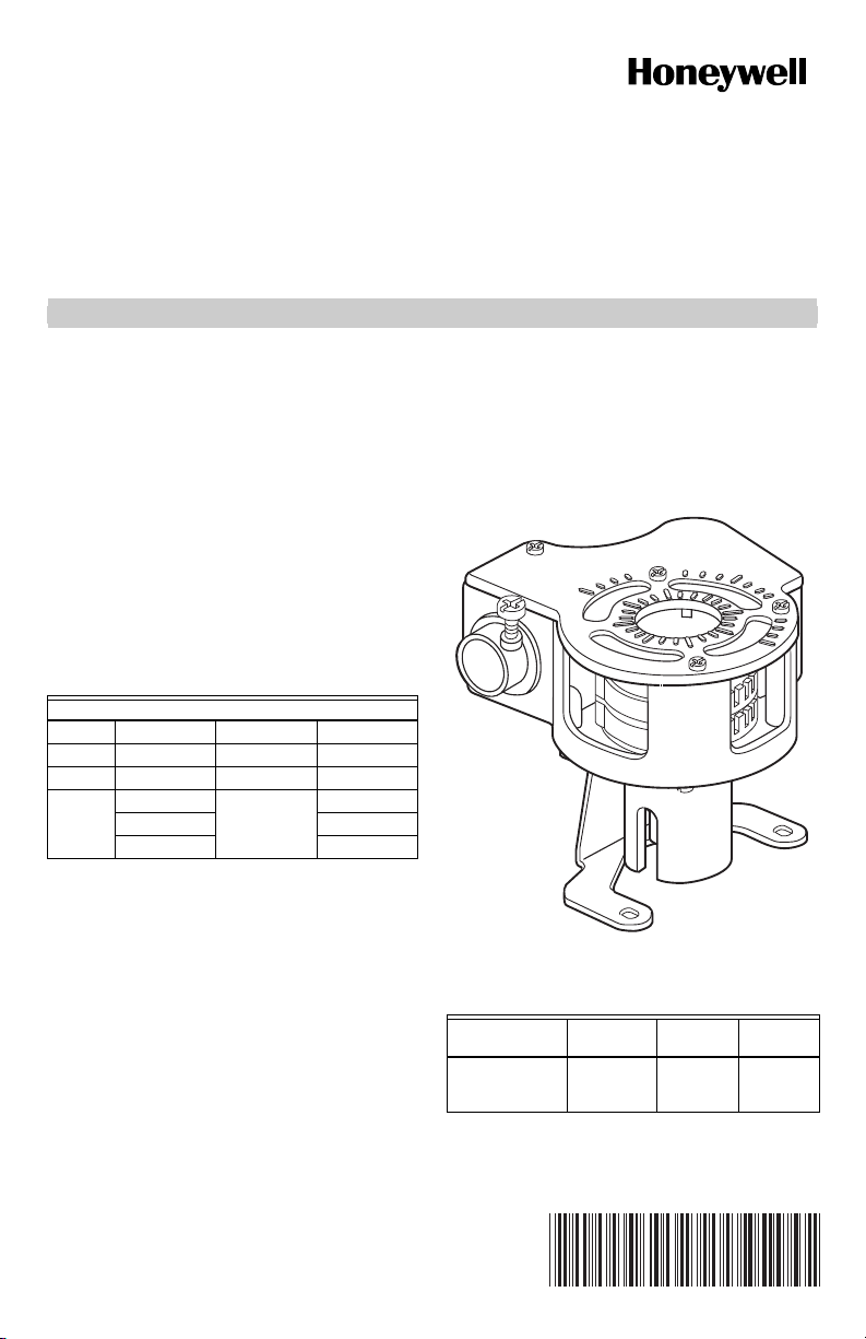
Package Contents (see Fig. 1):
Self-tapping mounting screws (2).
Switch assembly.
1m, 6-conductor cable.
3/8 in. flexible conduit connector.
Mounting bracket.
Dimensions: See Fig. 2.
Conduit (not included): 3/8 in. flexible.
Electrical Switch Ratings: See Table 2.
Operating Temperature: -40 to 130°F (-40 to 54°C).
Switch Differential: Three angular degrees maximum.
Switching: Two single-pole, double-throw (spdt) micro
switches.
Ratings and Approvals:
Underwriters Laboratories Inc. Listed: File No. E4436.
UL94-5V Plenum rating.
NEMA2.
Cable: UL Style 1180 rated 300V, 200°C, 18 gauge.
Fig. 1. Auxiliary switch.
Table 2. Electrical Switch Ratings.
Vol tag e
(maximum)
32003532-005 24 Vac
Class 2–
240 Vac
Resistive
Load
8A 2A
M22537
Inductive
Load
62-0212-01
Page 2
32003532-005 DUAL AUXILIARY SWITCH PACKAGE
4
(102)
3-5/8 (92)
3
(76)
M17518
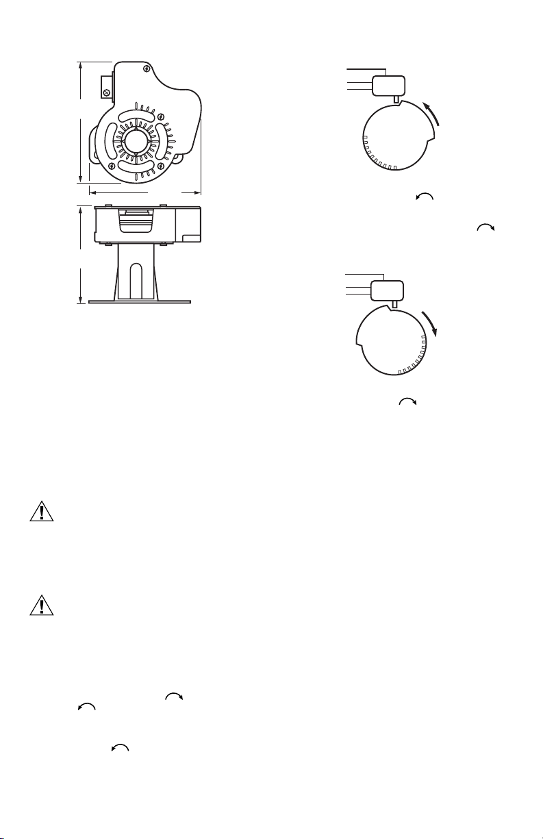
Fig. 2. Dimensions in in. (mm).
COM
NO
NC
CCW
M2160
Fig. 3. Switching configuration (top view)
for counterclockwise rotation.
Conversely, with the switch cam as shown in Fig. 4, the
normally closed contact opens during clockwise
rotation and the normally open switch closes.
COM
NO
NC
CW
INSTALLATION
When Installing this Product...
1. Read instructions carefully. Failure to follow them
could damage the product or cause a hazardous
condition.
2. Check ratings and descriptions given in
Specifications to make sure product is suitable for
your application.
3. Installer must be a trained, experienced service
technician.
4. After installation is complete, check out product
operation as provided in these instructions.
CAUTION
Electrical Shock or Equipment Damage
Hazard.
Can shock individuals or short equipment
circuitry.
Disconnect power supply before installation and
always keep device assembled.
CAUTION
Actuator Damage Hazard.
Turning motor output hub by hand or wrench
can damage internal gears.
Forcibly turning the motor shaft damages the gear
train.
1. Determine desired switching action (if switch is to
energize during clockwise or counterclockwise rotation).
NOTE: With switch cam as shown in Fig. 3, the
normally closed contact opens during counterclockwise rotation and the normally open
switch closes.
M2161
Fig. 4. Switching configuration (top view)
for clockwise rotation.
NOTE: Switches can be set prior to installation on the
actuator if angular switch positions are known.
2. Align the switch hub with the set screws on the
actuator. See Fig. 5.
3. If the conduit location is not appropriate for your
application, adjust the bracket as follows:
a. Remove and set aside the four bracket screws.
b. Rotate the bracket 90, 180, or 270 degrees.
c. Replace the bracket screws.
4. Mount the switch on the actuator and tighten the
two screws.
5. Determine switch position settings based on the
angular indications molded into the housing.
NOTES:
— Interior angular indications appear in
15 degree increments (see Fig. 6).
— Exterior angular indications appear in
10 degree increments (see Fig. 6).
— Four 10 degree indications are not on the
cover (see Fig. 6).
6. Move each cam inside switch assembly to the
appropriate position. Remember the direction
of travel of the cam for switching purposes (see Fig.
3 and 4). Monitor the switch closure with an ohmmeter for a continuity check. See Table 3.
IMPORTANT
Make certain that the switch activates at the
desired degree of stroke.
62-0212—01 2
Page 3

32003532-005 DUAL AUXILIARY SWITCH PACKAGE
10°
M17520
Fig. 5. ML4125 DCA with Auxiliary Switch.
Table 3. Proper continuity measurements.
Switch Normally Open Normally Closed
Activated Zero ohms Infinite ohms
Not Activated Infinite ohms Zero ohms
15°
Fig. 6. Auxiliary switch angular indications.
Wiring
CAUTION
Electrical Shock or Equipment Damage
Hazard.
Can shock individuals or short equipment
circuitry.
Disconnect power supply before installation and
always keep device assembled.
NOTE: See Table 4 for wiring information.
Table 4. Auxiliary Switch Wiring Connections.
Connection Upper Switch Lower Switch
Common Black/Red White/Red
Normally Closed Black/Yellow White/Yellow
Normally Open Black/Blue White/Blue
M17517
3 62-0212—01
Page 4

32003532-005 DUAL AUXILIARY SWITCH PACKAGE
By using this Honeywell literature, you agree that Honeywell will have no liability for any damages
arising out of your use or modification to, the literature. You will defend and indemnify Honeywell,
its affiliates and subsidiaries, from and against any liability, cost, or damages, including attorneys’
fees, arising out of, or resulting from, any modification to the literature by you.
Automation and Control Solutions
Honeywell International Inc. Honeywell Limited-Honeywell Limitée
® U.S. Registered Trademark
© 2008 Honeywell International Inc.
62-0212—01 M.S. Rev. 06-08
 Loading...