

Page 1

301EM
MODULE D’EXPANSION
EXPANSION MODULE
Manuel d’utilisateur
User Manual
Page 2

Page 3

Gas Detection Device
301EM
User Manual
ERP 512720
2/09
Page 4

Page 5

Notices and Trademarks
Copyright by Honeywell International Inc.
Release 512720 February 2009
While this information is presented in good faith and believed to be accurate,
Honeywell disclaims the implied warranties of merchantability for a particular
purpose and makes no express warranties except as may be stated in its written
agreement with and for its customers.
In no event is Honeywell liable to anyone for any indirect, special or consequential
damages. The information and specifications in this document are subject to
change without notice.
Honeywell Analytics
4005 Matte Blvd, Unit G
Brossard, Quebec, Canada, J4Y 2P4
301EM User Manual iii
Page 6

Page 7
Symbol Definitions
The following table lists the symbols used in this document to denote
certain conditions:
Symbol Definition
ATTENTI ON: Identifies information that requires
special consideration
TIP: Identifies advice or hints for the user, often
in terms of performing a task
REFERENCE _ INTERNAL: Identifies an
additional source of information within the
bookset.
Indicates a situation which, if not avoided, may
CAUTION
result in equipment or work (data) on the system
being damaged or lost, or may result in the
inability to properly operate the process.
CAUTION: Indicates a potentially hazardous
situation which, if not avoided, may result in minor
or moderate injury. It may also be used to alert
against unsafe practices.
CAUTION: Symbol on the equipment refers the
user to the product manual for additional
information. The symbol appears next to required
information in the manual.
WARNING: Indicates a potentially hazardous
situation which, if not avoided, could result in
serious injury or death.
WARNING symbol on the equipment refers the
user to the product manual for additional
information. The symbol appears next to required
information in the manual.
301EM User Manual v
Page 8

Page 9

Contents
INTRODUCTION ..............................................................9
Description ............................................................................................... 9
Intended Use ............................................................................................9
Unpacking ................................................................................................ 9
INSTALLATION INSTRUCTIONS .................................10
Installation Guidelines .......................................................................10
Wall Mount Installation ......................................................................10
Recommended Sensor Installation Heights ...........................................11
Determining the Number of Transmitters ..........................................12
Range and Alarm Levels ........................................................................13
Installing Optional Remote Sensors .......................................................14
WIRING DETAILS ..........................................................16
System Wiring ...................................................................................16
Power Connections ................................................................................17
Connecting sensors to transmitter .........................................................18
Communication to Controller .................................................................19
Relay Outputs ........................................................................................19
24 Vdc Output ........................................................................................20
4-20 mA Configuration ...........................................................................20
4-20 Output Configuration ......................................................................22
CALIBRATION / PROGRAMMING ................................ 27
User Interface ....................................................................................27
Operating Mode .....................................................................................27
Pushbutton Definitions ...........................................................................28
Programming the Unit ........................................................................29
Accessing the Programming Menus ..................................................30
Setting the Unit’s Address .................................................................31
Configuring a Sensor .........................................................................32
Changer the Sensor Address .................................................................32
Adding a new Sensor .............................................................................33
Removing a Sensor ...............................................................................34
301EM User Manual vii
Page 10

Adding Remote Panels ......................................................................34
Using the Service Menu ....................................................................35
Using the SetEvent Menu ..................................................................36
Changing Event Configurations .............................................................37
Using the SetRelay Menu ..................................................................40
Deactivating the Buzzer .....................................................................41
Configuring the Unit’s Alarms ............................................................42
Setting the Unit’s Analog Outputs ......................................................43
Calibrating the Unit ............................................................................44
Connecting the Hardware ......................................................................44
Adjusting the Zero (If Required) .............................................................45
Calibrating the Sensor ...........................................................................46
301EM Specifications ......................................................................48
301IRFS Specifications .....................................................................49
Maintenance ......................................................................................51
Replacement Parts ................................................................................51
Cleaning .................................................................................................51
APPENDIX A ..................................................................52
Available Pre-programmed configurations ........................................52
Type 1 CND (B-52 Canadian Standard for R123) .................................52
Type 2 CND (B-52 Canadian Standard for other Refrigerants) .............52
Type 3 US (ASHRAE 15 Standard for Refrigerants) .............................53
Type 4 (Default configuration - other than B-52 and ASHRAE 15) ........54
LIMITED WARRANTY ................................................... 55
Limited Warranty ....................................................................................55
Re-Stocking Policy .................................................................................55
Exclusions ..............................................................................................56
Warranty Limitation and Exclusion .........................................................56
Disclaimer of Unstated Warranties ........................................................57
Limitation of Liability ...............................................................................57
viii 301EM User Manual
Page 11

Introduction
Introduction
Description
Honeywell introduces a breakthrough innovation in refrigerant, toxic and
combustible gas monitoring as part of our continued commitment to
cutting-edge technology and customer satisfaction.
The result of extensive research and design, the 301EM uses the latest in
infrared technology. The 301EM can have up to 20 sensors connected to
allow for accurate monitoring of even the lowest gas concentration.
The 301EM (with an LCD display and keypad) can be installed in a
location separate from the detection area, making it safer to monitor gas
readings.
The 301EM also offers 4-20mA outputs, relay outputs, Modbus
communication, audible alarm options and is compatible with our 301C
controller.
Intended Use
The availability and costs associated with refrigerant gases make
monitoring a necessity for managing equipment rooms. A Honeywell
refrigerant detector provides early warning of refrigerant leaks, which
enhancing the refrigerant conservation strategy by monitoring
equipement room refrigerant gas concentrations. Toxic and combustible
sensors can be linked to the 301EM, allowing it to meet the broadest
range of customer requirements. The 301EM Expansion Module has
been carefully designed with several factory programmed configurations
that meet or exceed ASHRAE B-52 or 15-2201 standards.
Unpacking
After opening the package, remove the equipment and components.
Please make sure that all the items described on the order form or bill of
lading are actually in the box and are undamaged.
301EM User Manual 9
Page 12
Installation Instructions
Installation Guidelines
Installation Instructions
Installation Guidelines
These guidelines must be strictly observed to ensure that the equipment
will work properly. If they are not applied, Honeywell will not recognize any
liability in case of improper operation:
Make sure to locate all units easily accessible for proper service.
• Avoid any location where units could be subject to vibrations.
• Avoid any location close to any electromagnetic interference.
• Avoid any location where there are large temperature swings.
• Verify local requirements and existing regulations which may affect
the choice of location.
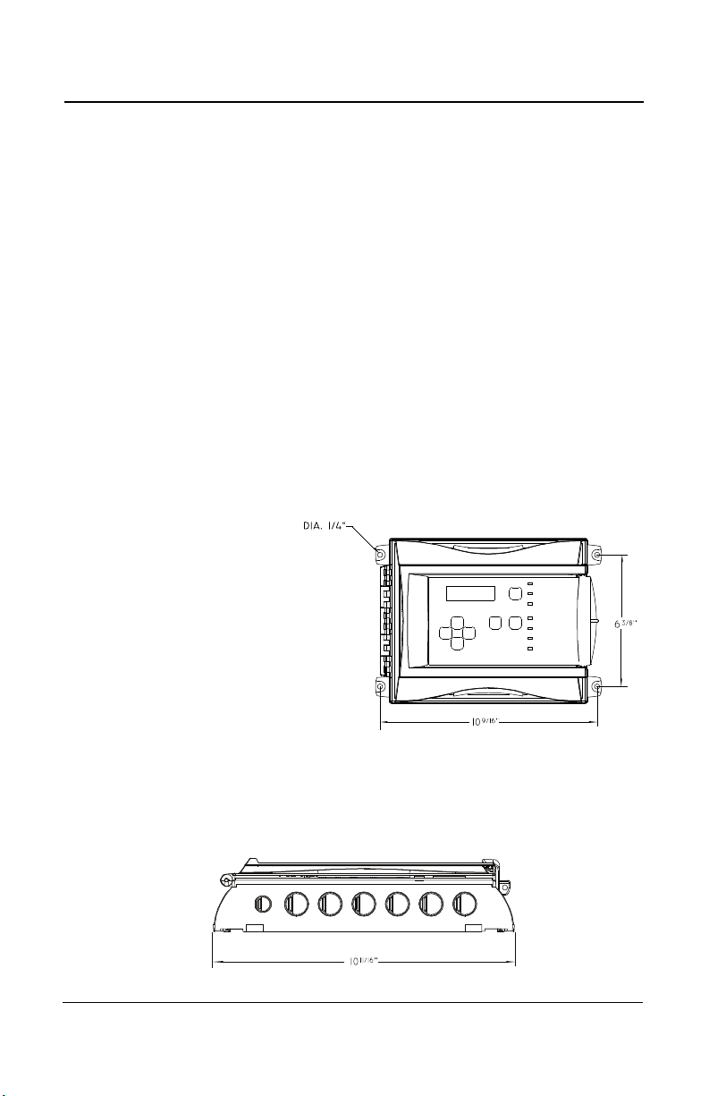
Wall Mount Installation
We recommend installing the
monitor at a height of 1.5 m
(4.9 ft) from the ground (eye
level).
• Mark two holes 162mm (6
3/8”) apart in height
• Mark two holes268.3mm
(10 9/16”) apart in width
• Drill 6.35mm (1/4”) holes
and prepare as necessary
• Mount unit with appropriate screws
Remember to pass all wiring through knock-outs at base of unit, using the
appropriate conduit.
10 301EM User Manual
Page 13

Installation Instructions
Wall Mount Installation
Recommended Sensor Installation Heights
The installation heights recommended represent general guidelines.
Always confirm with local laws and regulations before proceeding, as
these take precedence over manufacturer's recommendations.
Detected Gas
CO Carbon Monoxide 0.968 1 - 1.5 m (3 - 5 ft.) from floor
*NO2 Nitrogen Dioxide 1.58 (cold) 30 cm -1 m (1-3 ft.) from ceiling
H2 Hydrogen 0.07 30 cm (1 ft.) from ceiling
CL2 Chlorine 2.50 30 cm (1 ft.) from floor
H2S Hydrogen Sulfide 1.19 30 cm (1 ft.) from floor
O2 Oxygen 1.43 1 - 1.5 m (3 - 5 ft.) from floor
HCL Hydrogen Chloride 1.30 30 cm (1 ft.) from floor
HCN Hydrogen Cyanide 0.932 30 cm (1 ft.) from ceiling
ETO Ethylene Oxide 1.50 30 cm (1 ft.) from floor
SO2 Sulfur Dioxide 2.25 30 cm (1 ft.) from floor
R11 Refrigerants 5.04 30 cm (1 ft.) from floor
R12 Refrigerants 4.20 30 cm (1 ft.) from floor
R13B1 Refrigerants 5.14 30 cm (1 ft.) from floor
R114 Refrigerants 5.9 30 cm (1 ft.) from floor
R22 Refrigerants 3.11 30 cm (1 ft.) from floor
R123 Refrigerants 5.27 30 cm (1 ft.) from floor
R125 Refrigerants 4.14 30 cm (1 ft.) from floor
R134A Refrigerants 3.52 30 cm (1 ft.) from floor
R227 Refrigerants 5.90 30 cm (1 ft.) from floor
R245A Refrigerants 30 cm (1 ft.) from floor
R404A Refrigerants 3.43 30 cm (1 ft.) from floor
R407C Refrigerants 3.0 30 cm (1 ft.) from floor
R410A Refrigerants 3.0 30 cm (1 ft.) from floor
R507 Refrigerants 3.43 30 cm (1 ft.) from floor
R508b Refrigerants 30 cm (1 ft.) from floor
COMB Most combustibles are heavier than air, with the exception of methane,
hydrogen,ethylene and acetylene. Sensors for gases that are heavier than
air should be installed approximately 30 cm (1 foot) from the floor. For
combustibles that are lighter than air, sensors should be installed 30 cm (1
foot) from the ceiling, close to the potential leak source.
Relative Density
(air = 1)
Installation Height
* May differ in certain applications. Hot NO2 from exhaust systems is lighter than ambient air.
301EM User Manual 11
Page 14

Installation Instructions
Determining the Number of Transmitters
Determining the Number of Transmitters
The number of units required to protect an area is determined by the
unit’s detection radius, which depends on the type of gas detected, as
shown in the following table.
Gas Detected
CO Carbon monoxide 15 m (50 ft)
NO2 Nitrogen dioxide 15 m (50 ft)
Others 7 m (23 ft)
Surveillance
Radius
Area Covered
2
707 m
(7610 ft2)
2
707 m
(7610 ft2)
154 m2 (1658 ft2)
12 301EM User Manual
Page 15

Installation Instructions
Determining the Number of Transmitters
Range and Alarm Levels
Gas Detected Range Alarm A Alarm B Alarm C
CL2 Chlorine 0-15 ppm 0.5 ppm 1 ppm 13,5 ppm
CO Carbon monoxide 0-250 ppm 25 ppm 200 ppm 225 ppm
2S Hydrogen sulfide 0-50 ppm 10 ppm 15 ppm 45 ppm
H
2 Nitrogen dioxide 0-10 ppm 0.72 ppm 2 ppm 9 ppm
NO
O
2 Oxygen 0-25% Vol. 19.5% Vol. 22% Vol. 22,5% Vol.
SO2 Sulfur dioxide 0-10 ppm 2 ppm 5 ppm 9 ppm
R-123 Refrigerant 0-1000 ppm 50 ppm 500 ppm 900 ppm
R-11 Refrigerant 0-1000 ppm 250 ppm 500 ppm 900 ppm
R-12 Refrigerant 0-1000 ppm 250 ppm 500 ppm 900 ppm
R13B1 Refrigerant 0-1000 ppm 250 ppm 500 ppm 900 ppm
R114 Refrigerant 0-1000 ppm 250 ppm 500 ppm 900 ppm
R-22 Refrigerant 0-1000 ppm 250 ppm 500 ppm 900 ppm
R-125 Refrigerant 0-1000 ppm 250 ppm 500 ppm 900 ppm
R134A Refrigerant 0-1000 ppm 250 ppm 500 ppm 900 ppm
R227 Refrigerant 0-1000 ppm 250 ppm 500 ppm 900 ppm
R245A Refrigerant 0-1000 ppm 250 ppm 500 ppm 900 ppm
R404A Refrigerant 0-1000 ppm 250 ppm 500 ppm 900 ppm
R407C Refrigerant 0-1000 ppm 250 ppm 500 ppm 900 ppm
R410A Refrigerant 0-1000 ppm 250 ppm 500 ppm 900 ppm
R507 Refrigerant 0-1000 ppm 250 ppm 500 ppm 900 ppm
R508b Refrigerant 0-1000 ppm 250 ppm 500 ppm 900 ppm
Comb Combustibles 0-100% LEL 25% LEL 50% LEL 90% LEL
A different alarm level may have been programmed in order to satisfy the
constraints of a particular application.
Deadband and Accuracy
(Refrigerant detection)
The deadband is the area of signal or detection range where no action
occurs. The IRF deadband is 20 ppm.
301EM User Manual 13
Page 16
Installation Instructions
A
(white)
Power Comm.
sensor #5
sensor #6
sensor #7
sensor #8
External
Power
Supply
To next
sensors
B
(green)
V+ (red)
V- (black)
HPTV5DC8,
Input: 115 VAC 1A,
Output: 4.0A@6 and
12VDC, 2.5A@
24VDC
From
301EM
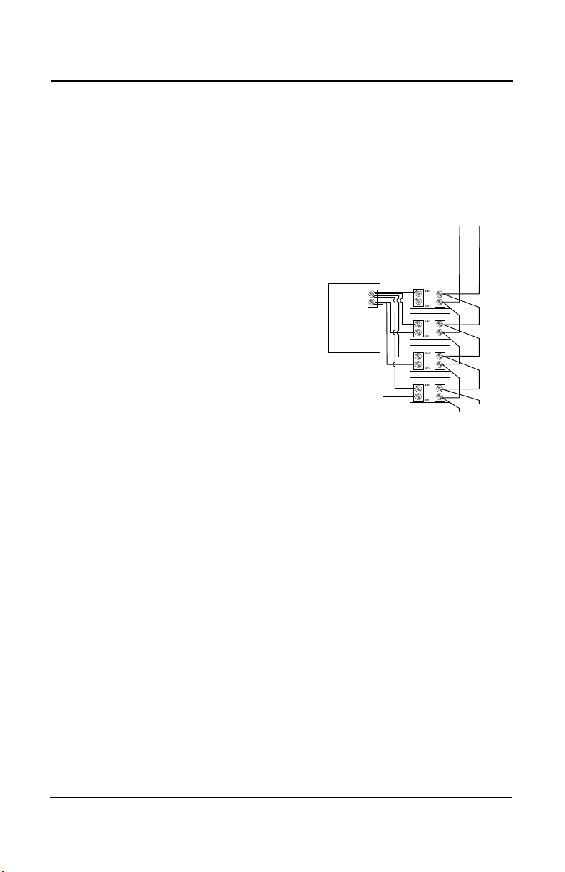
Determining the Number of Transmitters
Installing Optional Remote Sensors
301IRFS Sensor
The refrigerant sensor should be installed at the recommended height,
which is 30 cm (1 foot) from the floor.
Communication cables should be 2-24
AWG, twisted and shielded (Belden 9841
or equivalent), which should be connected
in a daisy chain from the 301EM (as
shown).
Power cables should be 14 AWG cable,
maximum length of 60 m (200 ft). The first
four sensor power cables may be wired
directly to the 301EM. Additional sensors
require an external power supply (one per
group of four sensors, to a maximum of 20
sensors in total), using the same rated
cable as units wired to the 301EM.
14 301EM User Manual
Page 17
Installation Instructions
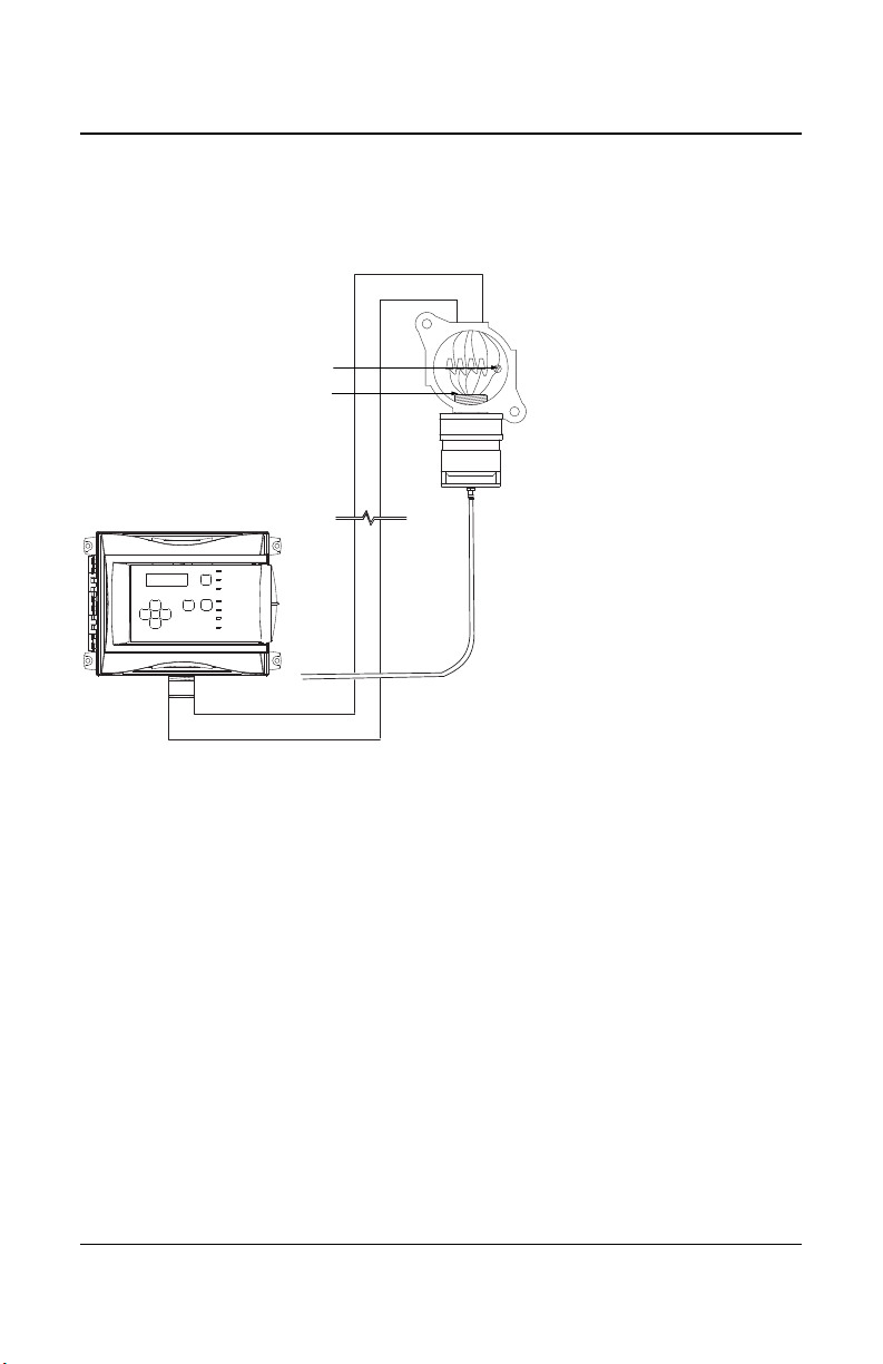
Monitor
Shielding must be grounded at the terminal
This housing not included
Calibration tubing
Thread dimension
3/4
Determining the Number of Transmitters
S301D2 Remote Sensor
The drawing below illustrates the connection for a 301D2 sensor with the
D2RS-PC option.
Communication: Use 224 AWG, twisted and
shielded cable (Belden
9841 or equivalent)
Power: Use 2-18 AWG
cable, maximum length of
160 m (500 ft).
301EM User Manual 15
Page 18
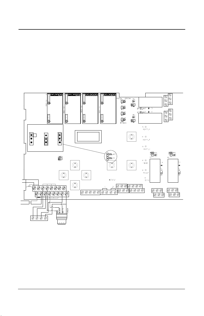
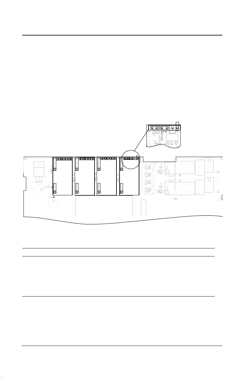
WIRING DETAILS
Contact
input
LCD screen
J8 J9
EOL Positions
Disabled
R
RC
GND BLACK WHITE
GREEN
ABAB
A
B
SHIELD
+-+-
J10
J1
6
J17
OUT #1
OUT #2
OUT #3
4@20
(4)
4@20
(3)
4@20
(2)
4@20
(1)
+ 4@20
- 4@20
N.O. N.C. N.O. N.C.
N.O.
N.C.
N.O.
N.C.
J6
J1
+VDC RED
V+
V+ V-
V-
24 IN
24
IN
DOWN
SW8
ESC
SW6
UP
SW2
ENTER
SW7
SW3
FAN
SW4
RESET
SILENCE
SW1
Sensor #1 IRF
ABV+ V-
Terminal J17
see page 20 for complete sensor wiring details
J13 J14
Terminals J8, J9
see pages 22, 25 and 27
for complete 4-20 wiring
details
Terminals J13, J14, J1, J6
See page 21 for complete
relay wiring instructions
Terminal J10
Used for communication
connections to a control
unit (such as 301C)
Terminal J16
Used (normally) to
connect a breakglass
switch (see page 23)
Sensor #2 GasPoint2
System Wiring
WIRING DETAILS
System Wiring
Both GasPoint II (301D2) and IRFS sensors can be linked to the 301EM
system. The drawing below illustrates an overview of PCB terminal
wiring.
.
16 301EM User Manual
Page 19
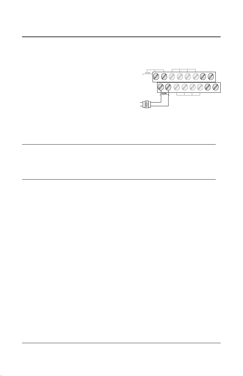
Power Connections
+VDC RED
V+ V-
24
IN
24
IN
The power requirement range is 22-27
Vac, 29-38 Vdc, 2.0 A max. The polarity is
not important. The system must be
grounded on the transformer.
A dedicated circuit-breaker must be
used.
Separate power supplies must be
provided for each group of 4 sensors
The 301EM requires a 100VA transformer that must be
installed near the unit to prevent voltage loss. If there is no
CAUTION
transformer, or if the transformer capacity is insufficient, 24
Vdc outputs will not have sufficient power, which will have an
impact on RFS/RFSA and other device options.
WIRING DETAILS
System Wiring
301EM User Manual 17
Page 20
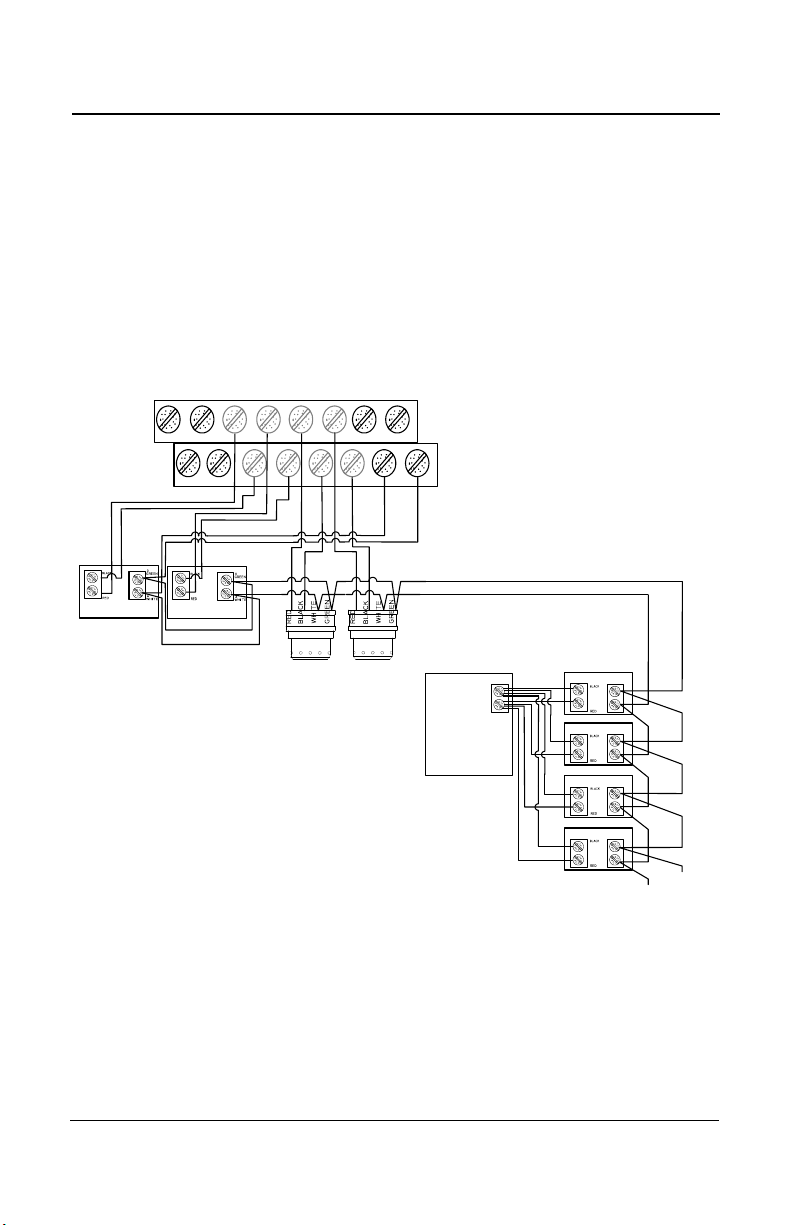
WIRING DETAILS
GND
BLACK
WHITE
GREEN
A
B
J17
+VDC RED
V+
V-
24
IN
sensor #3
S
e
n
s
o
r
#
1
S
e
n
s
o
r
#
2
S
e
n
s
o
r
#
3
S
e
n
s
o
r
#
4
A
(white)
Power Comm.
sensor #5
sensor #6
sensor #7
sensor #8
External
Power
Supply
To next
sensors
sensor #1
sensor #4
POWER:
Maximum 4 power
connections direct to unit.
Additional power sources
required for every group of 4
sensors.
COMMUNICATION:
Communication must be
connected in daisy chain
configuration.
B
(green)
V+ (red)
V- (black)
A
sensor #2
HPTV5DC8,
Input: 115 VAC 1A,
Output: 4.0A@6 and
12VDC, 2.5A@ 24VDC
System Wiring
Connecting sensors to transmitter
Connect the sensor to the transmitter as shown in the diagram below. The
maximum distance between sensor and power supply is 200 ft. (60 m) for
refrigerant and 500 ft. (160 m) for toxic and combustible gases. Color
coding (black, red, green, white) must be respected.
The first four sensors can be connected directly to the 301EM. Additional
sensors must have external power supplies (T300VA, 120/24Vac-300VA
Transformer) for every group of 4 sensors and communication must be in
daisy-chain connection
Note: Use 2-18 AWG wire gauge for toxic and explosives sensor power
wiring. Use 14 AWG wire gauge for refrigerant sensor power
wiring.
18 301EM User Manual
Page 21
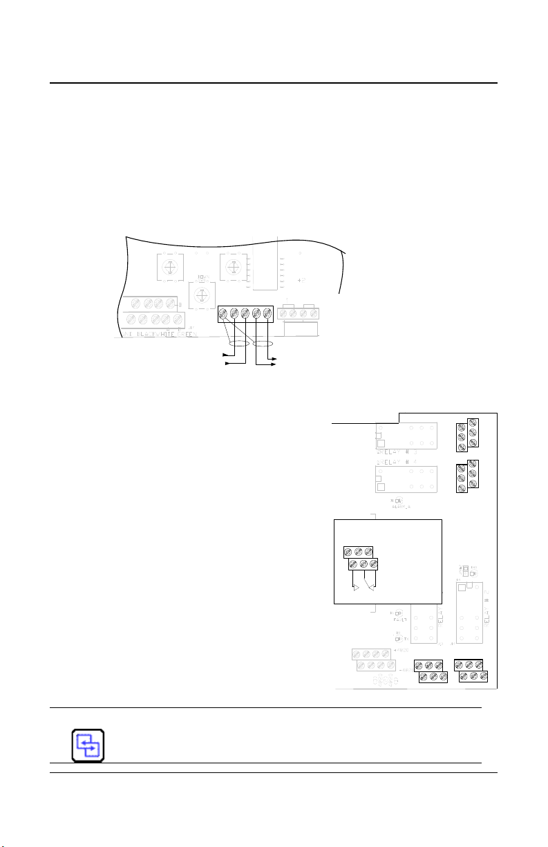
WIRING DETAILS
Previous
Next
Contact
input
J16
Communication Wire Gauge:
2-24 AWG (Belden 9841)
Twisted and shielded cable
2000 feet (600 m) per channel
T-tap: 65 feet (20 m) / T-tap
130 feet (40 m) total
COMMUNICATION
SHIELD A B A B
J10
N.O. N.C.
N.O. N.C.
N.O.
N.C.
N.O.
N.C.
RELAY OUTPUTS
3+5
4+6
1+3
2+4
Normally
open
Normally
closed
5
31
642
System Wiring
Communication to Controller
Terminal J10 is for communication connections from the 301EM to the
301C Controller. The cables must be grounded using the shield terminal.
The network can be up to 2000 ft. (609 m) per channel. The length of a Ttap can be a maximum of 65 feet (20 m). A maximum of 130 ft. (40 m) for
all the T-taps must be respected.This diagram illustrates network
communication wiring on terminal J10; wires come in from a previous
device and go out to the next device.
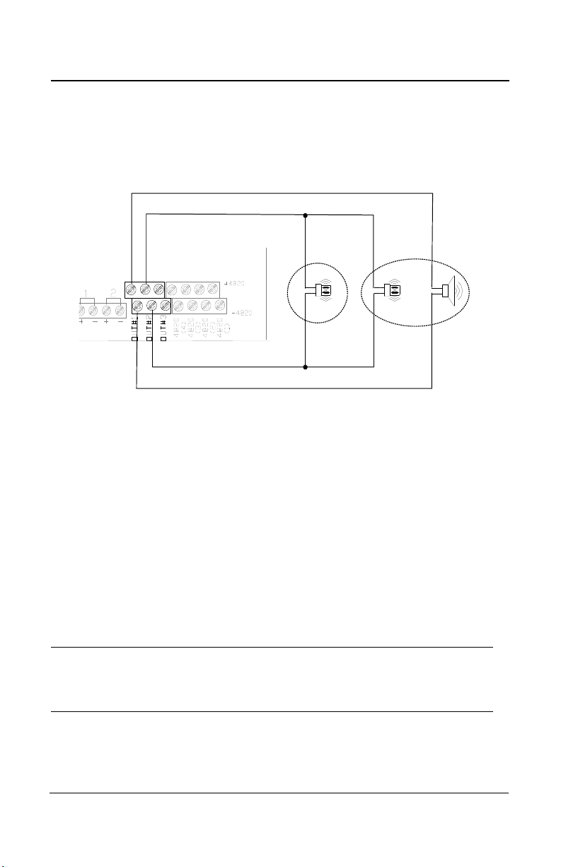
Relay Outputs
The relay outputs will withstand up to 5 amps
at 30 Vdc or 250 Vac (resistive load only).
They can be used to activate horns, strobes,
etc. Refer to the drawing for proper wiring.
Failsafe Relay Outputs
When power is applied to the 301EM, these
relays are also powered up. The devices
connected to these outputs will be triggered
when power is cut, which allows detection of
power failures or interruptions.
The 301EM is factory configured in Normal
mode, which means that the relay outputs
are not in failsafe mode.
See the APPENDIX section for more details about B-52 and
ASHRAE 15 standard configurations.
301EM User Manual 19
Page 22
WIRING DETAILS
Contact
input
J8 J9
RFS
RFSA
System Wiring
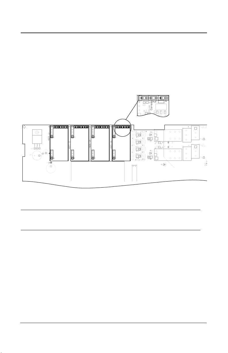
24 Vdc Output
The three 24 Vdc / 250 mA outputs are provided to activate DC horn,
strobe, etc.
Note: Terminal connectors labeled OUT #1 and OUT #2 must be
dedicated to RFSA use only, if applicable.
Terminal connector labeled OUT #3 must be used for RFS only, if
applicable.
RFS: Optional built-in stobe
RFSA: Optional built-in stobe and horn
4-20 mA Configuration
Output 4-20 mA, J9
The 4-20 mA output option will provide a real time analog readout of the
gas concentration read by the 301EM for each of its sensors. It can be
connected to a third party controller, DDC, BMS, etc.
Polarity must be observed.
CAUTION
20 301EM User Manual
Do not apply electrical power to the 301EM until all
connections are made. Significant damage can result from
incorrect wiring.
Page 23
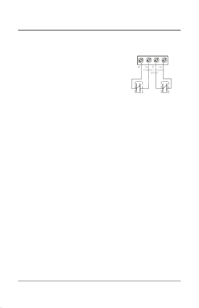
Contact Input, J16
Contact 1
Contact 2
J16
The contact input is mainly used to connect a
manual break glass switch to comply with the
mechanical code. It is also possible to
connect a third break glass switch in series if
needed.
The drawing illustrates the ASHRAE 15
configuration where:
Contact 1 = Electrical shut down (ASHRAE 15
config.)
Contact 2 = Fan activation (ASHRAE 15 config.)
WIRING DETAILS
System Wiring
301EM User Manual 21
Page 24
WIRING DETAILS
System Wiring
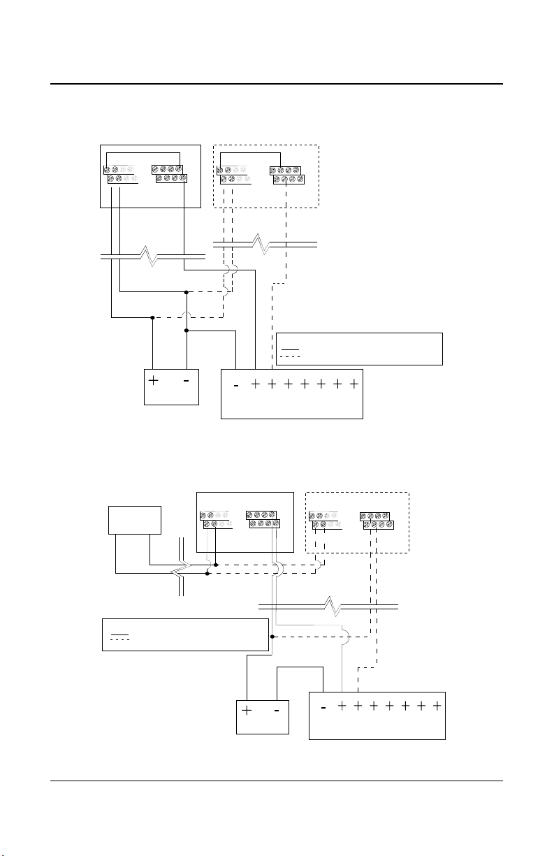
4-20 Output Configuration
4-20 mA Current Sourcing Output Configuration
The transmitter supplies the loop current. The maximum impedance
supported by the loop is 400 ohms. Set jumpers on JP4 at 1-2, 3-4 and 5-
6.
A dedicated power supply must be used with each 301EM.
CAUTION
22 301EM User Manual
Considerable damage may occur if this condition is not strictly
followed.
Page 25
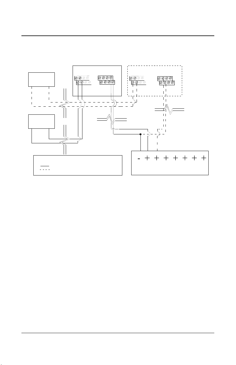
Current Sourcing Output Configuration
DDC SYSTEM
24 VAC
24 VAC
24 VAC
24 VAC
4-20 mA
4-20 mA
- MORE THAN ONE TRANSMITTER CONNECTED
- ONE TRANSMITTER CONNECTED
LEGEND
TRANSMITTER 1
TRANSMITTER X
J9 J9J16J16
V+
V-
V+
V-
+4@20
-4@20
+4@20
-4@20
Sensor #1
Sensor #2
Sensor #3
Sensor #4
Sensor #1
Sensor #2
Sensor #3
Sensor #4
WIRING DETAILS
System Wiring
301EM User Manual 23
Page 26
WIRING DETAILS
System Wiring
Output Loop-Powered Operation
(Factory Setting)
The 4-20 mA output is factory set for loop-powered operation and
requires a power source of 12 Vdc to 30 Vdc. The overall impedance
depends on the voltage supplied at the 4-20 mA loop. Set jumpers on
JP4 at 2-3, 4-5 and 6 for this type of configuration.
Permitted Impedance in the 4-20 mA Loop
Voltage Source Applied Total Impedance
12 Vdc 400 Ohms
16 Vdc 600 Ohms
20 Vdc 800 Ohms
24 Vdc 1,000 Ohms
30 Vdc 1,300 Ohms
24 301EM User Manual
Page 27
3 Wire Configuration
DDC SYSTEM
24 VDC
24 VAC 24 VAC 4-20 mA4-20 mA
MORE THAN ONE TRANSMITTER CONNECTED
ONE TRANSMITTER CONNECTED
LEGEND
TRANSMITTER 1
TRANSMITTER X
J9 J9J16J16
V+
V-
V+
V-
+4@20
-4@20
+4@20
-4@20
Sensor #1
Sensor #2
Sensor #3
Sensor #4
Sensor #1
Sensor #2
Sensor #3
Sensor #4
DDC SYSTEM
24 VDC
24 VAC 24 VAC 4-20 mA4-20 mA
- MORE THAN ONE TRANSMITTER CONNECTED
- ONE TRANSMITTER CONNECTED
LEGEND
TRANSMITTER 1
TRANSMITTER X
24 VAC
J9 J9J16J16
V+
V-
V+
V-
+4@20
-4@20
+4@20
-4@20
Sensor #1
Sensor #2
Sensor #3
Sensor #4
Sensor #1
Sensor #2
Sensor #3
Sensor #4
4 Wire Configuration
WIRING DETAILS
System Wiring
301EM User Manual 25
Page 28

Page 29

Programming and Calibration
User Interface
Programming and Calibration
User Interface
When power is initially applied, the unit’s LCD screen will display the
product’s name and firmware version.
Operating Mode
Normal Mode When the 301EM is in Normal mode, no user
intervention is required. The display will scroll to
display (gas and concentration) readings from up to 20
sensors. The Tx LED will blink when there is a
transmission on the communication channel (if the unit
is connected to a controller)
Alarm Mode Red LEDs light according to the alarm level detected
(Alarm A, B or C). If the unit is equipped with a horn or
strobe, these will also be activated with the
corresponding alarm.
Fault Mode If a sensor has communication problems, the yellow
Fault LED lights. This LED will also light when the
service alarm is activated.
Programming The programming mode is password protected.
Mode Only qualified technicians should access this mode.
The enter key provides access to programming and
confirms an entry, while the arrow keys allow
technicians to increase or decrease values and scroll
throughout the menus.
301EM User Manual 27
Page 30
Programming and Calibration
User Interface
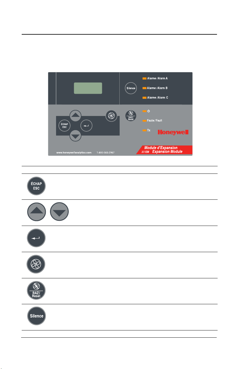
Pushbutton Definitions
The 301EM has “pushbuttons” that serve as an interface to the unit’s
programming functions. Below is a description for each button’s function:
Key Description
Used to exit the menus or cancel an input. Also used to
stop the alternating reading between the connected
sensors.
Used to scroll through the sensor data displays or through
menus or to change a specific value.
Serves as an “enter” key and is used to access a
programming field or to confirm a specific value.
Fan start switch (For B-52 or ASHRAE 15 programming).
See the Events table
Used to reset all outputs after system returns to normal
operating mode (linked to the Reset function in the Events
menu).
Turns off the buzzer and horns
28 301EM User Manual
Page 31

Programming and Calibration
Programming the Unit
Programming the Unit
The 301EM is equipped with a programming menu that allows users to
modify certain parameters and to calibrate the unit.
Menu Option Description
Password Provides password restricted access to programming
menus
Set Adr. Lets users select a specific address for the device
Mem SD Inactive option: Reserved for technicians’ use only
Sensor Lets users add or remove a sensor
Set #RP Lets users add up to ten 301EMRP units
Service Lets users specify different Service alarm settings
SetEvent Lets users configure specific events for some or all sensor
types
SetRelay Lets users specify whether a relay will be set to failsafe
Buzzer Lets users activate or deactivate the silence button
Set Alr Lets users set specific minimum and maximum alarm levels
(for alarms A, B and C)
SetAnOut Lets users adjust the 4-20 outputs
Set Zero Lets users adjust the sensor zero
Set Span Lets users calibrate each sensor
Quit Lets users exit the programming menus
301EM User Manual 29
Page 32

Programming and Calibration
PASSWORD
A
A
Accessing the Programming Menus
Accessing the Programming Menus
Acces to the 301EM’s programming is password protected for security
reasons. The password is “VA”.
• Press the enter key to access the programming menus. The
PASSWORD screen is displayed
• The first letter is underlined. Press the up or down arrow to change
the letter until V is displayed
• Press Enter to confirm. The next letter is underlined. Press the up or
down arrow until A is displayed
• Press Enter to confirm the password and access the menus
30 301EM User Manual
Page 33

Programming and Calibration
Menu
Set Adr.
Set ADR
M001 V01
Setting the Unit’s Address
Setting the Unit’s Address
The 301EM is shipped with the default address set to 1. If you are using
the unit in a network, this menu lets you select a specific address,
according to your network configuration.
• Access the menu and use the arrows to scroll to the Set Adr. menu
and press enter to select
• The Set Adr. menu is displayed. Use the arrows to change the
address and press enter when the desired address (Modbus
addresses M001 to M254 and Vulbus addresses V01 to V30) is
displayed.
• The screen returns to the main menu
Make certain that no two devices share an address as this
may result in network conflicts
301EM User Manual 31
Page 34

Programming and Calibration
Menu
Sensor
Sensor
Chg Adr.
NO2 #1
SD #1
Configuring a Sensor
Configuring a Sensor
The Sensor menu option allows users to add a new sensor, to scan for
new sensors or to remove a sensor. Access the menu and use the arrows
to scroll to the Sensor menu and press enter to select.
There are now 4 possible actions available: NewSens?, Chg Adr., Scan
SD, Disable. Use the arrows to scroll up or down through these options
and press enter to select.
Note: The NewSens? menu is reserved for and should only be used
by qualified technicians.
Changer the Sensor Address
This menu lets users change the sensor’s address (position) in the
301EM. Pay special attention when changing a sensor’s address that you
do not change to an address that is already in use as this will replace the
existing sensor.
• Scroll to the Chg Adr. menu and press enter to select.
• The screen displays the sensor gas type, sensor # and its address.
Use the arrows to scroll through the sensors until the desired sensor
is displayed.
32 301EM User Manual
Page 35

Programming and Calibration
NO2 #1
For #2 ?
Sensor
Scan SD
Scan sd
sd3 164
Configuring a Sensor
• Press enter to select the sensor. The screen displays the sensor gas
type and its address. Use the arrows to scroll to the address desired
(between 1 and 20) and press enter to confirm.
The sensor’s address has been changed.
Adding a new Sensor
This menu lets users add new sensors (to expand the network or to
replace an expired sensor).
When adding new sensors, it is important to add one sensor
at a time to ensure proper address assignment.
• Scroll to the Scan SD menu option and press enter to select.
The device searches for any new sensor and assigns the new sensor the
first available address. The screen displays a wait message while the
device searches for the sensor.
When the device has found the sensor, it displays the sensor device
address (its position in the 301EM) and its firmware version.
301EM User Manual 33
Page 36

Programming and Calibration
Sensor
Disable?
Menu
Set #RP
Set #RP
0 EMRP
Adding Remote Panels
Removing a Sensor
This menu lets users remove a sensor from the 301EM.
• Scroll to the Disable? menu option and press enter to select.
Adding Remote Panels
The Set #RP menu lets users add up to 10 remote panels (301EMRP) to
the 301EM’s network.
• Scroll to the Set #RP menu option and press enter to select.
• In the Set #RP screen, use the arrows to scroll the the desired
number (since you can add up to ten remote panels you can select a
number between 1 and 10) and press enter to select.
Once entered into the 301EM’s network, the remote panels will display or
announce the status of the 301EM’s sensors.
34 301EM User Manual
Page 37

Programming and Calibration
Menu
Service
Service
Set Act
Set Time
12 Month
Using the Service Menu
Using the Service Menu
The Service menu allows users to configure several service related
options, such as when and how to activate service alarms. Service alarms
are used to signal when a sensor needs to be replaced or calibrated.
This menu contains two options: Set Act and Set Time.
The Set Act menu lets users select the action that will be taken. Available
options are: Fault, OFF or Visual
Fault: A service alarm will be activated whenever there is a fault
status
OFF: No service alarm will be triggered at any time (factory default
setting)
Visual: Only a visual service alarm will be activated
The Set Time menu lets users configure a specific deadline at which a
service alarm will be activated.
Use the arrows to scroll between 12 to 24 months to trigger a service
alarm after the specified number of months in service. Select the Reset
option to turn off the Service alarm for a period of 100 days (after the
alarm was triggered).
301EM User Manual 35
Page 38

Programming and Calibration
Menu
SetEvent
SetEvent
Type1CND
Using the SetEvent Menu
Using the SetEvent Menu
Although the 301EM is fully configured with specific event configurations
(see the tables in Appendix A for details on available configurations), it is
nonetheless possible to modify events to suit different applications.
• Scroll to the SetEvent menu and press enter to select.
If this is the initial setup and no previous events have been configured,
you must select the event configuration (Type) from the menu (see the
tables in Appendix A for details).
• Use the arrows to scroll through the options and press enter to select.
The available options (described in greater detail in Appendix A) are:
Type1 CND, Type2 CND, Type3 US, Type # 4 and OTHER.
Note: Selecting the “OTHER” event type creates an event with all fields
and events blank. Therefore, no events will appear when pressing
the arrows. Events must be created before they appear in the scroll
list.
Once the configuration type has been selected, it can no
longer be changed without erasing ALL events and
reconfiguring the system anew. Consult the tables in
Appendix A to make certain that the appropriate event
configuration is selected.
36 301EM User Manual
Page 39

Programming and Calibration
Type1CND
Event# 1
Event# 1
SD All
EraseALL
No?
Using the SetEvent Menu
Changing Event Configurations
The various event menus allow users to modify standard configurations or
to create completely customized event configurations, based on their
needs. Each event menu provides a set of four options, which also
contain a subset of options, as described below.
The first screen that appears is the main event screen. Press enter to
select the event displayed or use the arrows to scroll through the event
numbers to select a specific event.
The first event screen lets users specify which sensors will be linked to
the event. The screen displays SD All (the default value). Press enter to
enable the field and use the arrows to scroll through the available options.
When the desired option is displayed press enter to select.
SD All: Applies the event action to all sensors
SD #1: (through SD #4) Applies the event action to only the selected
sensor
ManSW#1:(through ManSW#2) Applies the event action to the selected
switch
SD #---: Displays the EraseALL screen. When “Yes?” is
selected from the Event #1 menu, all
configuration data for events will be erased.
Note that when “SD #---” is selected at any other event
number, the EraseALL screen does not appear and only the
data for the active event number will be erased (and events
will change numbers, moving up one).
When you have selected the option and pressed enter, the field is
disabled and you can proceed to the next screen. Use the arrows to
move ahead one screen.
301EM User Manual 37
Page 40

Programming and Calibration
Event# 1
= ALRA
EraseALL
No?
Using the SetEvent Menu
The second event screen lets users specify what will trigger an event. The
screen displays ALRA (the default value).
• Press enter to enable the field and use the arrows to scroll through
the options:
= ALRA: (through ALRC) Links the event to Alarm A, B or C
= Fault: Links the event to a fault condition
= ALL: Links the event to all conditions (alarm and fault)
= ---: Displays the EraseALL screen. When “Yes?” is
selected from the Event #1 menu, all configuration
data for events will be erased.
Note that when “---” is selected at any other event number, the
EraseALL screen does not appear and the data for the active
event number will be erased (and events will change numbers,
moving up one).
If ManSW#1(or #2) was selected at the previous step this
screen will only have 2 options: Open or Closed.
Set to Open if the output is set to Normally Closed, or to
Closed if the output is set Normally Open.
When you have selected the option and pressed enter, the field is
disabled and you can proceed to the next screen. Use the arrows to
move ahead one screen.
38 301EM User Manual
Page 41

Programming and Calibration
Event# 1
REL #1
EraseALL
No?
Event# 1
RESET N?
Using the SetEvent Menu
The third event screen lets users specify the actions linked to the event.
The screen displays REL #1 (the default value).
• Press enter to enable the field and use the arrows to scroll through
the options:
REL #1: (through REL #4)Triggers the devices connected to the
selected relay
OUT #1: (through OUT #3)Triggers the devices connected to the
selected Output
BUZZER: Triggers the audible alarm for this event
---: Displays the EraseALL screen. When “Yes?” is
selected from the Event #1 menu, all configuration
data for events will be erased.
Note that when “---” is selected at any other event number, the
EraseALL screen does not appear and the data for the active
event number will be erased (and events will change numbers,
moving up one).
When you have selected the option and pressed enter, the field is
disabled and you can proceed to the next screen. Use the arrows to
move ahead one screen.
The final screen, RESET, lets users specify that an event will remain
active, even after it has returned to normal.
• Press enter to enable the field and use the arrows to scroll to Y?.
• Press enter once again to activate the Reset function.
Note: The Reset key on the front panel lets you deactivate the event
301EM User Manual 39
Page 42

Programming and Calibration
Menu
SetRelay
Using the SetRelay Menu
Using the SetRelay Menu
The SetRelay menu lets users specify whether the the relay for the event
will be in failsafe mode and whether the Silence button on the user
interface (front of housing) will be enabled for this event.
Press enter to select the menu and use the arrows to scroll through the
options:
FAILSAFE? Puts the relay in Failsafe mode (the default setting is no
failsafe).
Silence Enables the Silence button function of the user
interface for this event.
When you have selected the option and pressed enter, the field is
disabled and you can proceed to the next screen. Use the arrows to
move to the next menu.
40 301EM User Manual
Page 43

Programming and Calibration
Menu
Buzzer
Silence
Yes?
Key Beep
No?
Deactivating the Buzzer
Deactivating the Buzzer
The 301EM is shipped with the buzzer function activated by default. This
menu lets you activate or deactivate the Silence button on the keypad and
to silence or activate the key beep function.
• Access the menu and use the arrows to scroll to the Buzzer menu
and press enter to select. The display moves to the next screen.
•The Silence screen displays Yes?, press enter to select (or scroll to
No? to disable the Silence button). The keypad Silence button is
enabled; when the buzzer sounds, pressing the silence button will
turn the buzzer off.
• The next screen, Key Beep, allows you to activate a sound for any
key activation. Use the arrows to display either Yes or No and press
enter to confirm.
• The screen returns to the main menu
301EM User Manual 41
Page 44

Programming and Calibration
Menu
Set Alr
H2S #1
SD #1
H2S #1
Min AlrA
Min AlrA
9.0 PPM
Configuring the Unit’s Alarms
Configuring the Unit’s Alarms
Although the 301EM is shipped with the default alarm settings, this menu
allows you to set specific minimum and maximum levels for alarms A, B
and C.
• Access the menu and use the arrows to scroll to the Set Alr. menu
and press enter to select
• The menu displays the first sensor’s information screen. Use the up or
down arrows to scroll between sensors and press enter when the
desired sensor is displayed.
• The next six screens let you modify both the minimum and maximum
alarm setting for all alarm levels (A, B, C). Use the arrows to scroll
and press enter to select the desired alarm.
• In the selected alarm screen, use the arrows to increase or decrease
the value and press enter to confirm the desired value.
• The screen returns to the first sensor menu
Repeat these steps for each alarm level to modify.
42 301EM User Manual
Page 45

Programming and Calibration
Menu
SetAnOut
SetAnOut
Set Min 1
Set Min1
AdjAnOut
Set Min1
*WAIT*
Setting the Unit’s Analog Outputs
Setting the Unit’s Analog Outputs
This menu lets you adjust each of the four analog outputs, minimum and
maximum (e.g. the 4 and the 20).
Note that this menu does not display how the output is being
adjusted. The Output must be connected (to an ammeter or
to the DDC) for readings to be viewed.
• Access the menu and use the arrows to scroll to the SetAnOut. menu
and press enter to select.
•The SetAnOut menu is displayed. In this menu, you can scroll to
select the output (from Min 1 to Min 4 and Max 1 to Max 4) and press
enter to select.
•The AdjAnOut screen appears. Press on the up arrow to increase
the analog output value or the down arrow to decrease (the 301EM’s
screen does not change or display any changes; the value will only be
visible on the connected meter).
• When the desired output value is reached, press enter to confirm.
The screen displays *WAIT* while the unit is reinitialized.
• The screen returns to the main menu.
Repeat these steps for each output to adjust.
301EM User Manual 43
Page 46

Programming and Calibration
or
17 Liter
Span
Calibration
Gas Cylinder
103 Liter
Span
Calibration
Gas Cylinder
Refrigerant sensor calibration
Calibrating the Unit
Calibrating the Unit
Honeywell provides its customers with specialized gas detection
equipment. Beyond the warranty period, the systems must be maintained
and calibrated on a regular basis (normally twice a year).
If unit span or zero cannot be adjusted, the sensor may be approaching
its end-of-life and must be replaced. Keep an operation log of all
maintenance, calibrations and alarm events.
The unit requires warm-up time before being put into service and
calibrated. The warm-up time required depends on the type of sensor,
however a standard minimum of fifteen (15) minutes is recommended.
Connecting the Hardware
1. Plug the calibration adaptor onto the gas sensor inlet.
2. Screw the regulator to the appropriate calibration gas cylinder (for
either span or zero adjustment) and set the flow rate (see Table I on
page 47).
3. Connect the tubing to the regulator outlet and to the calibration
adaptor or to calibration port.
44 301EM User Manual
Page 47

Programming and Calibration
PASSWORD
A
A
Menu
Set Zero
H2S #1
SD #1
H2S #1
GoCalib?
Menu
*Quit*
Calibrating the Unit
Adjusting the Zero (If Required)
When the unit displays 0 %/ppm in an area with no presence of the target
gas, proceed to “Calbibrating the Sensor” on the following page.
To adjust the zero, inject zero gas (nitrogen) at the specified flow rate.
The gas must be allowed to flow into the unit for a minimum of 2.5 minutes
before beginning and then throughout the adjustment.
1. Press enter to access the programming menu.
Since the menus are password protected you
must first enter the password in the PASSWORD
screen
2. Use the up or down button to change each letter
until VA is displayed. Press enter after each letter
to confirm and to access the menus.
3. Use the up or down arrow to scroll to the Set Zero
menu screen and press enter to select.
4. Use the up or down arrow to select the sensor to
be calibrated and press enter to select.
5. Press enter again when the screen displays
GoCalib to start the zero adjustment
6. The Wait screen is displayed throughout the
adjustment and the menu returns to the main
menu screen when the adjustment is complete.
7. Use the up or down arrow to scroll to the Quit
menu and press enter to exit the programming
menus.
301EM User Manual 45
Page 48

Programming and Calibration
PASSWORD
A
A
Menu
Set Span
H2S #1
SD #1
SetGas
25.0 PPM
Menu
*Quit*
Calibrating the Unit
Calibrating the Sensor
To calibrate the sensor, inject the calibration gas at the specified flow rate.
The gas must be allowed to flow into the unit for a minimum of 2.5 minutes
before beginning and then throughout the calibration.
1. Press enter to access the programming menu.
Since the menus are password protected you
must first enter the password in the PASSWORD
screen
2. Use the up or down button to change each letter until VA is displayed.
Press enter after each letter to confirm and to access the menus.
3. Use the up or down arrow to scroll to the Set Span
menu screen and press enter to select.
4. Use the up or down arrow to select the sensor to
be calibrated and press enter to select.
5. The next screen, SetGas, allows users to specify
a calibration gas value. Use the up or down arrow
to increase or decrease the value and press enter
to confirm.
6. Press enter again when the screen displays
GoCalib to start the calibration
7. The gas concentration is displayed throughout the
calibration and the menu returns to the main
menu screen when the adjustment is complete.
8. Use the up or down arrow until the Quit menu is
displayed and press enter to exit the programming
menus.
46 301EM User Manual
Page 49

Programming and Calibration
Calibrating the Unit
Table I - Calibration Information
Gas Scale Warm-up Flow Rate Notes
Combustible 0 - 102% LEL 15 min. 500 ml/min 1% Volume CH4 =
20% LEL CH4.
CL2 0 - 15.3 ppm 15 min. 500 ml/min
CO 0 - 255 ppm N/A 500 ml/min
H2S 0 - 51.0 ppm 15 min. 500 ml/min
* HF 0 - 10.2 ppm 15 min. 500 ml/min Nitrogen dioxide is
a surrogate gas for
HF
NO2 0 - 10.2 ppm 15 min. 500 ml/min
O2 0 - 25.5% N/A 500 ml/min
SO2 0 -10.2 ppm 15 min. 500 ml/min
Refrigerant
Rxxx
0 - 1000 ppm 15 min 100 ml/min Replace the xxx by
the required
refrigerant
* Discontinued products: Only existing sensors will be supported.
301EM User Manual 47
Page 50

Programming and Calibration
301EM Specifications
301EM Specifications
Power 22-27 Vac, 50/60 Hz
29-38Vdc, 2 A@ 29 Vdc
Standard Outputs: 4 DPDT relays
3 Outputs at 24 Vdc @ 250 mA each
Optional Outputs: 4-20 mA for each sensor
Communication RS-485: Modbus or Vulbus
Audible Alarm: 65 dBA @ 1 m (3 ft)
Display : Backlit LCD
Visual Indicators: Green LED: Normal operation
Red LEDs: Alarm A, B and C
Yellow LED: Fault/service alarm
Amber LED: Tx (Activated in network mode)
Length of lines: Up to 2000 feet (609 m) between 301EM
and controller
T-tap: 65 ft. (20 m) maximum per t-tap, to a
total of 130 ft. (40 m)
Relay Output Rating: 5A, 30Vdc or 250Vac (resistive load)
Circuit Protection: Long Time-Lag Polyswitch Type TT
Overvoltage Category: II
Operating Environment: Indoor Use
Operating Temperature Range: 0 to 40°C (32°F to 100°F)
Operating Humidity Range: 0 to 95% RH (non-condensing)
Operating Altitude: Up to 3000m (9843 feet)
Enclosure: NEMA 4X ABS - Polycarbonate indoor
Pollution Degree: 2
Size (HxWxD): 20.3 x 28 x 7 cm
7.99” x 11.02” x 2.76”
Weight: 1.02 kg (2.26 lbs)
Certifications ANSI/UL 61010-1
CAN/CSA C22.2 No. 61010-1
Optional Horn: 105dBA, 4-28V, 2800Hz (RFSA)
Min. Voltage 80 dB(A) min. @ 2 ft and 6 Vdc
Max Voltage 90 dB(A) min. @ 2 ft and 28
Vdc
Optional Strobe: STAS flashing LED
48 301EM User Manual
Page 51

Programming and Calibration
301IRFS Specifications
301IRFS Specifications
Gases Detected: R11, R12, R13B1, R22, R114, R123,
R125, R134a, R227, R245A, R404A,
R407C, R410A, R507, R508b
Sensor power requirements: 8.5 - 12.5 Vdc, 1A@10 Vdc Maximum
Sensing Technology: Infrared sensor
Measurement Range: 0-1000 ppm
Resolution: 1 ppm
Deadband: 20 ppm
Accuracy: ±10ppm à 50 ppm / ±40ppm à 500 ppm
Response Time (T90): 60 seconds
Warmup time 15 minutes
Operating Environment: Indoor Use
Operating Temperature Range: 0 to 40°C (32°F to 100°F)
Operating Humidity Range: 0 to 95% RH (non-condensing)
Enclosure: ABS - Polycarbonate
Size (HxWxD): 10.2 x 28 x 6.3 cm
4.02” x 11.02” x 2.48”
Weight: 0.603 kg (2.33 lbs)
The 301EM sensor LED has 2 functions. If the sensor is working properly,
the LED will blink according to the sensor addresses on the 301EM. In
that case, the LED will blink as shown:
Address 1 = The LED blinks 2 times during 2,8 seconds
Address 2 = The LED blinks 3 times during 2,8 seconds
Address 3 = The LED blinks 4 times during 2,8 seconds
Address 4 = The LED blinks 5 times during 2,8 seconds
Addresses 5 to 20 = The LED blinks once during 2,8 seconds
If the sensor is connected to a 301IRF, the LED will be on during 0,2
seconds and off during 2,6 seconds (blinking). If the sensor has a
problem (failsense), the LED will remain on.
301EM User Manual 49
Page 52

Programming and Calibration
301IRFS Specifications
301D2 Sensor Specifications
Sensing technology: Electrochemical (toxic)
Catalytic combustion (combustible)
Diffusion fuel cell (oxygen)
Sensor power requirements:
Length of lines: Up to 160m (500 feet ) between 301EM
Operating Temperature Range: Toxic: -40 to 40°C (-40°F to 100°F)
Operating Humidity Range: 0% to 95% RH, non-condensing
Operating Altitude: Up to 3000m (9843 feet )
Enclosure: Class 1, Division 1, Groups B, C, D
Toxic: 7 - 9 Vdc, 25mA@ 8 Vdc
Combustible : 7 - 9 Vdc, 100mA@ 8 Vdc
and sensor (toxic and combustible)
Combustible: -40 to 50°C (-40°F to 112°F)
50 301EM User Manual
Page 53

Programming and Calibration
Maintenance
Maintenance
The 301EM requires no maintenance. Transmitters, however, require
regular inspection and calibration.
Replacement Parts
LED replacement instructions for RFS or RFSA option:
• Turn the cap until the diamond shape aligns with the triangle outline
shape
• Pull off the cap
• Use the insertion tool to remove the LED;
• Use the insertion tool to put in the new LED;
• Put the cap back on (press down firmly)
• Turn the cap until the diamond is aligned with the white triangle
shape.
Due to the continuous evolution of our products, please contact our
service department for ordering parts or for more details.
Technical Support Line: 1-800-563-2967
Cleaning
Clean the exterior with a soft, damp cloth. Do not use solvents, soaps or
polishers.
301EM User Manual 51
Page 54

APPENDIX A
Available Pre-programmed configurations
APPENDIX A
Available Pre-programmed configurations
Type 1 CND (B-52 Canadian Standard for R123)
SetEvent Input Status Output Reset Silence
Event # 1 SD All Alr A Relay #1 Yes No
Event # 2 SD All Alr A Relay #4 Yes No
Event # 3 SD All Alr A Out 1 Yes Yes
Event # 4 SD All Alr A Out 2 Yes No
Event # 5 SD All Alr A Out 3 Yes No
Event # 6 SD All Alr A Buzzer Yes Yes
Event # 7 SD All Alr A Relay #2 Yes Yes
Event # 8 SD All Alr A Relay #3 Yes No
Event # 9 SD All Fault Relay #3 Yes No
Event #10 SD All Alr B Relay #1 No No
Event #11 SD All Alr C Relay #1 No No
Type 2 CND (B-52 Canadian Standard for other Refrigerants)
Event Input Status Output Reset Silence
Event # 1 SD All Alr A Relay #1 Yes No
Event # 2 SD All Alr A Out 1 Yes Yes
Event # 3 SD All Alr A Out 2 Yes No
Event # 4 SD All Alr A Out 3 Yes No
Event # 5 SD All Alr A Buzzer Yes Yes
Event # 6 SD All Alr A Relay #2 Yes Yes
Event # 7 SD All Alr B Relay #4 Yes No
Event # 8 SD All Alr A Relay #3 Yes No
Event # 9 SD All Fault Relay #3 Yes No
Event #10 SD All Alr C Relay #1 No No
52 301EM User Manual
Page 55

APPENDIX A
Available Pre-programmed configurations
Type 3 US (ASHRAE 15 Standard for Refrigerants)
Event Input Status Output Reset Silence
Event # 1 SD All Alr A Relay #1 Yes No
Event # 2 SD All Alr A Out 1 Yes Yes
Event # 3 SD All Alr A Out 2 Yes No
Event # 4 SD All Alr A Out 3 Yes No
Event # 5 SD All Alr A Buzzer Yes Yes
Event # 6 SD All Alr A Relay #2 Yes Yes
Event # 7 SD All Alr B Relay #4 No No
Event # 8 SD All Alr A Relay #3 Yes No
Event # 9 SD All Fault Relay #3 No No
Event #10 ManSw #1* Open Relay #1 Yes No
Event #11 ManSw #1* Open Relay #4 Yes No
Event #12 ManSw #1* Open Out 1 Yes Yes
Event #13 ManSw #1* Open Out 2 Yes No
Event #14 ManSw #1* Open Out 3 Yes No
Event #15 ManSw #1* Open Buzzer Yes Yes
Event #16 ManSw #1* Open Relay #2 Yes Yes
Event #17 ManSw #1* Open Relay #3 Yes No
Event #18 SD All Alr C Relay #1 No No
Event #19 ManSw #2** Open Relay #1 No No
*Mansw #1 Trigger an electrical shut down.
**ManSw #2 Trigger relay #1.
301EM User Manual 53
Page 56

APPENDIX A
Available Pre-programmed configurations
Type 4 (Default configuration - other than B-52 and ASHRAE 15)
Event Input Status Output Reset Silence
Event # 1 SD All Alr A Relay #1 No No
Event # 2 SD All Alr B Relay #2 No Yes
Event # 3 SD All Alr C Relay #3 No No
Event # 4 SD All Fault Relay #4 No No
Event # 5 SD All Alr B Out 1 No Yes
Event # 6 SD All Alr A Out 2 No No
Event # 7 SD All Alr C Out 3 No No
Event # 8 SD All Alr B Buzzer No Yes
54 301EM User Manual
Page 57

Limited Warranty
Limited Warranty
Limited Warranty
Honeywell Analytics, Inc. warrants to the original purchaser and/or
ultimate customer ("Purchaser") of Vulcain products ("Product") that if any
part thereof proves to be defective in material or workmanship within
twelve (12) months, such defective part will be repaired or replaced, free
of charge, at Honeywell Analytics' discretion if shipped prepaid to
Honeywell Analytics at 4005 Matte Blvd., Unit G, Brossard, Quebec,
Canada, J4Y 2P4, in a package equal to or in the original container. The
Product will be returned freight prepaid and repaired or replaced if it is
determined by Honeywell Analytics that the part failed due to defective
materials or workmanship. The repair or replacement of any such
defective part shall be Honeywell Analytics' sole and exclusive
responsibility and liability under this limited warranty.
Re-Stocking Policy
The following re-stocking fees will apply when customers return products
for credit:
• 15% re-stocking fee will be applied if the product is returned within 1
month following the shipping date
• 30% re-stockingfee will be applied if the product is returned within 3
months following the shipping date
A full credit (less re-stocking fee) will only be issued if the product is in
perfect working condition. (If repairs are required on the returned product,
the cost of these repairs will be deducted from the credit to be issued.)
No credits will be issued beyond the three month period.
301EM User Manual 55
Page 58

Limited Warranty
Exclusions
a.If Gas sensors are part of the Product, the gas sensor is covered by
a twelve (12) month limited warranty of the manufacturer.
b.If gas sensors are covered by this limited warranty, the gas sensor
is subject to inspection by Honeywell Analytics for extended exposure
to excessive gas concentrations if a claim by the Purchaser is made
under this limited warranty. Should such inspection indicate that the
gas sensor has been expended rather than failed prematurely, this
limited warranty shall not apply to the Product.
c.This limited warranty does not cover consumable items, such as
batteries, or items subject to wear or periodic replacement, including
lamps, fuses, lves, nes, sensor elements, cartridges, or filter
elements.
Warranty Limitation and Exclusion
Honeywell Analytics will have no further obligation under this limited
warranty. All warranty obligations of Honeywell Analytics are
extinguishable if the Product has been subject to abuse, misuse,
negligence, or accident or if the Purchaser fails to perform any of the
duties set forth in this limited warranty or if the Product has not been
operated in accordance with instructions, or if the Product
serial number has been removed or altered.
301EM User Manual 56
Page 59

Limited Warranty
Disclaimer of Unstated Warranties
The warranty printed above is the only warranty applicable to this
purchase. All other warranties, express or implied, including, but not
limited to, the implied warranties of merchantability or fitness for a
particular purpose are hereby disclaimed.
Limitation of Liability
It is understood and agreed that Honeywell Analytics’ liability, whether in
contract, in tort, under any warranty, in negligence or otherwise shall not
exceed the amount of the purchase price paid by the purchaser for the
product and under no circumstances shall Honeywell Analytics be liable
for special, indirect, or consequential damages. The price stated for the
product is a consideration limiting honeywell analytics' liability. No action,
regardless of form, arising out of the transactions under this warranty may
be brought by the purchaser more than one year after the cause of
actions has occurred.
301EM User Manual 57
Page 60

Page 61

Dispositif de détection de gaz
301EM
Manuel d’utilisateur
ERP 512720
2/09
Page 62

Page 63

Avis et marques de commerce
Tous droits réservés par Honeywell International Inc.
Parution 512720 février 2009
Quoique cette information est présentée en bonne foi et est présumée exacte,
Honeywell décline la garantie tacite de la qualité marchande pour un emploi
particulier et offre aucune garantie exprès, à l’exception des conventions écrites
avec et pour ses clients.
Honeywell ne sera, sous aucune circonstance, responsable à qui que ce soit pour
des dommages spéciaux ou indirectes. Les informations et les spécifications
dans ce document sont susceptibles d’être modifiées sans préavis.
Honeywell Analytics
4005 Matte Blvd, Local G
Brossard, Québec, Canada, J4Y 2P4
Manuel de l’utilisateur 301EM iii
Page 64

Page 65

Définitions des symboles
Le tableau suivant contient la liste des symboles utilisés dans ce
document pour indiquer certaines conditions :
Symbole Définition
ATTENTI ON: Identifie une information demandant
une attention spéciale
Truc: Identifie un conseil ou un truc pour
l’utilisateur, souvent concernant une tâche
RÉFÉRENCE- INTERNE Indique une source
d’information supplémentaire à l’intérieur du
document.
Indique une situation à éviter pouvant entraîner des
ATTENTION
dommages au système ou la perte de travail
(documents) ou pouvant prévenir l’opération
normale du système.
ATTENTI ON : Indique une situation potentiellement
dangereuse qui peut entraîner des blessures
mineures ou modérées si pas évité. Peut
également signaler des actions dangereuses
ATTENTI ON: Un symbole sur l’équipement qui
réfère l’utilisateur à la documentation pour de plus
amples informations. Ce symbole apparaît à côté
des informations nécessaires dans le manuel.
AVERTISSEMENT : Indique une situation
potentiellement dangereuse qui peut entraîner des
blessures majeures ou la mort si pas évité.
AVERTISSEMENT Un symbole sur l’équipement
qui réfère l’utilisateur à la documentation pour de
plus amples informations. Ce symbole apparaît à
côté des informations nécessaires dans le manuel.
Manuel de l’utilisateur 301EM v
Page 66

Page 67

Table des matières
INTRODUCTION ...........................................................11
Description ........................................................................................11
Application visée ...............................................................................12
Déballage .........................................................................................12
INSTRUCTIONS D’INSTALLATION .............................13
Directives générales .............................................................................13
Installation murale ..................................................................................13
Hauteurs d’installation recommandées ..................................................14
Déterminer le nombre de transmetteurs ...........................................15
Plage de détection et niveaux d’alarmes ...........................................16
Installation des sondes à distances ..................................................17
DÉTAILS DE CONNEXION ...........................................19
Câblage du système ..........................................................................19
Connexion d’alimentation .......................................................................20
Connexion des sondes .........................................................................21
Communication ......................................................................................22
Sorties relais ..........................................................................................22
Sorties 24 Vcc ........................................................................................23
Configurations 4-20mA ..........................................................................23
Configuration sortie 4-20 mA .................................................................25
Manuel de l’utilisateur 301EM vii
Page 68

ÉTALONNAGE / PROGRAMMATION ...........................29
Interface usager ................................................................................29
Modes d’opération .................................................................................29
Description des touches .........................................................................30
Comment programmer l’unité ............................................................31
Comment accéder au menu de programmation ................................31
Comment désactiver l’alarme sonore ................................................32
Comment configurer l’adresse de l’unité ...........................................33
Comment configurer les alarmes .......................................................34
Comment configurer les sorties analogiques ....................................35
Comment étalonner l’unité .................................................................36
Brancher les régulateurs ........................................................................36
Étalonnage du zero (si requis) ...............................................................37
Étalonnage du gain ................................................................................38
Spécifications 301EM ........................................................................40
Spécifications sonde 301IRFS .........................................................41
Spécifications sonde 301D2 .............................................................42
Entretien ............................................................................................43
Pièces de remplacement ......................................................................43
Nettoyage ..............................................................................................43
ANNEXE ........................................................................44
Configurations pré-programmées disponibles ..................................44
GARANTIE LIMITÉE ......................................................47
Garantie limitée ......................................................................................47
Politique de Retour ................................................................................47
Exclusions ..............................................................................................47
Limitation et exclusion de la garantie .....................................................48
Dénégation de responsabilité d’autres garanties ...................................49
Limitation de responsabilité ...................................................................49
viii Manuel de l’utilisateur 301EM
Page 69

Introduction
INTRODUCTION
Description
À la recherche de technologies de pointe et de la satisfaction du client,
Honeywell présente une innovation dans le contrôle des gaz frigorigènes,
toxiques et explosifs.
Fruit de la recherche et d'une conception poussée, le 301EM utilise la
technologie infrarouge la plus avancée. Le 301EM peut gérer jusqu’à 20
détecteurs, ce qui permet la mesure précise d’infimes concentrations de
gaz. La sonde peut être placée à une distance allant jusqu'à 500 pi. de la
source d’alimentation pour le contrôle de gaz toxique et 200 pi. pour le
gaz frigorigène.
L'émetteur, équipé d'un affichage à CL rétroéclairé et d’un clavier de
touches, peut être installé à la hauteur des yeux dans un emplacement
différent de la zone de lecture des gaz frigorigènes. La surveillance se fait
donc d'un site sûr et éloigné.
Le 301EM offre également des sorties 4-20 mA et des relais, une
communication Modbus, des options d'alarmes sonores et il est
compatible avec notre contrôleur 301C.
Application visée
En raison de la disponibilité et des coûts croissants des gaz frigorigènes,
il devient nécessaire d’effectuer une surveillance accrue dans les salles
mécaniques. Le détecteur de frigorigène Honeywell fournit un
avertissement rapide lors de fuite de gaz et indique les concentrations de
gaz de la salle mécanique, ce qui permet d’améliorer la stratégie de
conservation du frigorigène. De plus, des sondes toxiques et
combustibles peuvent être jumelées au 301EM afin de rencontrer un plus
large éventail d’exigences pour la clientèle. Offert dans une configuration
spéciale, le module d'expansion 301EM a été soigneusement conçu pour
rencontrer et même dépasser les normes ASHRAE B-52 et 15-2201.
Déballage
Dès l’ouverture de l’emballage, assurez-vous que vous avez reçu
l’équipement et les composantes tels qu’indiqués sur le bon de
connaissement et que l’ensemble de la commande n’est pas
endommagé.
Manuel de l’utilisateur 301EM 9
Page 70

Instructions d’installation
Directives générales
INSTRUCTIONS D’INSTALLATION
Directives générales
Ces directives doivent être strictement respectées pour assurer le bon
fonctionnement de l’équipement. Si elles ne sont pas respectées,
Honeywell ne se tiendra aucunement responsable des incidents pouvant
en découller:
• Localiser chaque unité à un endroit facile d’accès pour un technicien.
• Éviter toute localisation des unités près des sources de vibrations.
• Évitez d’installer les unités près d’équipements émettant des
interférences électromagnétiques.
• Évitez les emplacements où la température change rapidement.
• Avant de débuter l’installation, vérifiez tous les codes, normes ou
législations pouvant affecter le choix de l’emplacement.
Installation murale
Nous recommandons d’installer
le moniteur à 1.5 m (4.9 pi) du
sol.
Mesurer les distances, tel
qu’indiqué :
• Distance en hauteur entre les
trous 162mm (6 3/8”)
• Distance en largeur entre les
trous 268.3mm
(10 9/16”)
• Perçer les trous 6.35mm (1/
4”) et fixer l’unité avec les vis
appropriées.
Le câblage de l’unité doit être enfiler dans les trous de pastilles
poinçonnées (knock-out) situés en dessous de l’unité.
10 Manuel de l’utilisateur 301EM
Page 71

Instructions d’installation
Directives générales
Hauteurs d’installation recommandées
Les hauteurs d'installation de détecteurs recommandées représentent des directives
générales. Toujours vérifier les normes et les lois locales avant de procéder à
l'installation. Celles-ci ont préséance sur les recommandations du fabricant.
Gaz Détectés Densité relative
CO Monoxyde de carbone 0.968 1-1.5 m (1-1.5 pi) du sol
NO2 Dioxyde d’azote 1.58 (froid)* 30 cm -1 m (1-3 pi) du plafond
H2 Hydrogène 0.07 30 cm (1 pi) du plafond
CL2 Chlore 2.50 30 cm (1 pi) du sol
H2S Sulfure d’hydrogène 1.19 30 cm (1 pi) du sol
O2 Oxygène 1.43 1 - 1.5 m (1 - 1.5 pi) du plancher
HCL Chlorure d’hydrogène 1.30 30 cm (1 pi) du sol
HCN Acide cyanidrique 0.932 30 cm (1 pi) du plafond
ETO Oxyde d’éthylène 1.50 30 cm (1 pi) du sol
SO2 Bioxyde de souffre 2.25 30 cm (1 pi) du sol
R11 Frigorigènes 5.04 30 cm (1 pi) du sol
R12 Frigorigènes 4.20 30 cm (1 pi) du sol
R13B1 Frigorigènes 5.14 30 cm (1 pi) du sol
R114 Frigorigènes 5.9 30 cm (1 pi) du sol
R22 Frigorigènes 3.11 30 cm (1 pi) du sol
R123 Frigorigènes 5.27 30 cm (1 pi) du sol
R125 Frigorigènes 4.14 30 cm (1 pi) du sol
R134A Frigorigènes 3.52 30 cm (1 pi) du sol
R227 Frigorigènes 5.90 30 cm (1 pi) du sol
R245A Frigorigènes
R404A Frigorigènes
R407C Frigorigènes
R410A Frigorigènes
R507 Frigorigènes
R508b Frigorigènes
La plupart des combustibles sont plus lourds que l’air, excepté le méthane,
l’hydrogène, l’éthylène et l’acétylène. Pour les gaz plus lourd que l’air, des
Comb
* Peut varier dans certaines applications. Le NO2 chaud sortant d’un dispositif d'échappement est plus
léger que l’air ambient.
capteurs devraient être installés à environ 30 cm du sol. Pour les
combustibles plus légers que l’air, des capteurs devraient être installés à
30 cm du plafond, près de la source potentielle de fuite.
(air = 1)
3.43
3.0
3.0
3.43
Manuel de l’utilisateur 301EM 11
Hauteur d’installation
30 cm (1 pi) du sol
30 cm (1 pi) du sol
30 cm (1 pi) du sol
30 cm (1 pi) du sol
30 cm (1 pi) du sol
30 cm (1 pi) du sol
Page 72

Instructions d’installation
Déterminer le nombre de transmetteurs
Déterminer le nombre de transmetteurs
Le nombre de transmetteurs est déterminé par le rayon de surveillance
de l'appareil. Le rayon de surveillance dépend du gaz détecté. Voir les
valeurs correspondantes dans le tableau ci-dessous.
Gaz Detecté
CO Monoxyde de carbone 15 m (50 pi)
Dioxyde d’azote 15 m (50 pi)
2
NO
Autres 7 m (23 pi)
Rayon de
surveillance
Surface couverte
2
707 m
707 m
154 m
(7610 pi
2
(7610 pi
2
(1658 pi2)
2
)
2
)
12 Manuel de l’utilisateur 301EM
Page 73

Instructions d’installation
Plage de détection et niveaux d’alarmes
Plage de détection et niveaux d’alarmes
Gaz détectés Plage Alarme A Alarme B Alarme C
CL2 Chlore 0-15 ppm 0.5 ppm 1 ppm 13,5 ppm
CO
ETO Oxyde d’éthylène 0-20 ppm 1 ppm 5 ppm 18 ppm
H
H2S Sulfure d’hydrogène 0-50 ppm 10 ppm 15 ppm 45 ppm
HCL Chlorure d’hydrogène 0-25 ppm 3 ppm 4 ppm 22,5 ppm
HCN Acide cyanhydrique 0-50 ppm 5 ppm 9 ppm 45 ppm
NO2 Dioxyde d’azote 0-10 ppm 0.72 ppm 2 ppm 9 ppm
O2 Oxygène 0-25% Vol. 19.5% Vol. 22% Vol. 22.5% Vol.
SO2 Bioxyde de souffre 0-10 ppm 2 ppm 5 ppm 9 ppm
R-123 Frigorigène 0-1000 ppm 50 ppm 500 ppm 900 ppm
R-11 Frigorigène 0-1000 ppm 250 ppm 500 ppm 900 ppm
R-12 Frigorigène 0-1000 ppm 250 ppm 500 ppm 900 ppm
R13B1 Frigorigène 0-1000 ppm 250 ppm 500 ppm 900 ppm
R114 Frigorigène 0-1000 ppm 250 ppm 500 ppm 900 ppm
R-22 Frigorigène 0-1000 ppm 250 ppm 500 ppm 900 ppm
R-125 Frigorigène 0-1000 ppm 250 ppm 500 ppm 900 ppm
R134A Frigorigène 0-1000 ppm 250 ppm 500 ppm 900 ppm
R227 Frigorigène 0-1000 ppm 250 ppm 500 ppm 900 ppm
R245A Frigorigène 0-1000 ppm 250 ppm 500 ppm 900 ppm
R404A Frigorigène 0-1000 ppm 250 ppm 500 ppm 900 ppm
R410A Frigorigène 0-1000 ppm 250 ppm 500 ppm 900 ppm
R507 Frigorigène 0-1000 ppm 250 ppm 500 ppm 900 ppm
R508b Frigorigène 0-1000 ppm 250 ppm 500 ppm 900 ppm
Comb. Combustibles 0-100% LIE 25% LIE 50% LIE 90% LIE
Monoxyde de
carbone
2 Hydrogène 0-100% LIE 25% LIE 50% LIE 90% LIE
0-250 ppm 25 ppm 200 ppm 225 ppm
Un seuil d'alerte différent a pu être programmé afin de satisfaire la
contrainte d'une application particulière.
Manuel de l’utilisateur 301EM 13
Page 74

Instructions d’installation
A
(white)
Alimentation Comm.
détecteur #5
détecteur #6
détecteur #7
détecteur #8
Aux
détecteurs
suivants
B
(green)
V+ (red)
V- (black)
Du
301EM
HPTV5DC8,
Entrée: 115 VAC 1A,
Sortie: 4.0A@6 and
12VDC, 2.5A@ 24VDC
Alimentation
externe
Installation des sondes à distances
Zone morte et précision
(Détection de frigorigène)
La zone morte (deadband) est la zone de signal ou de plage de détection
où il n’y a aucune action. La zone morte du IRF est à 20 ppm.
Installation des sondes à distances
Sonde à distance 301IRFS
Le détecteur de frigorigène doit être installé à la hauteur recommandée,
soit à 30 cm (1 pied) du sol.
Utiliser le calibre de câble 2-24 AWG,
torsadé, blindé (Belden 9841 ou
équivalent) pour la communication. La
communication doit être en marguerite,
selon le dessin.
Utiliser le calibre de câble 14 AWG, sur
une longueur maximum de 60 m (200 pi)
pour l’alimentation. Seulement 4
détecteurs peuvent être connectés
directement au 301EM. Tout autre
détecteur doit avoir une alimentation
externe (par groupe de quatre, jusqu’au
maximum de 20 détecteurs).
14 Manuel de l’utilisateur 301EM
Page 75

Instructions d’installation
Moniteur
Le blindage doit être mis à la terre
Ce boîtier non fournit
Tube d'étalonnage
Dimension
de filet 3/4" NPT
Installation des sondes à distances
Sonde à distance S301D2
Ce schéma représente une connexion avec une sonde 301D2 avec
option D2RS-PC.
Communication:
Utiliser le calibre de
câble 2-24 AWG,
torsadé, blindé (Belden
9841 ou équivalent)
Alimentation: Utiliser le
calibre de câble 2-18
AWG, sur une longueur
maximum de 160 m
(500 pi).
Manuel de l’utilisateur 301EM 15
Page 76

Détails de connexion
Contact
input
LCD screen
J8 J9
EOL Positions
Disabled R
RC
GND BLACK WHITE
GREEN
ABAB
A
B
SHIELD
+-+-
J10 J16
J17
OUT #1
OUT #2
OUT #3
4@20
(4)
4@20
(3)
4@20
(2)
4@20
(1)
+ 4@20
- 4@20
N.O. N.C. N.O. N.C.
N.O.
N.C.
N.O.
N.C.
J6
J1
+VDC RED
V+
V+ V-
V-
24
IN
24
IN
DOWN
SW8
ESC
SW6
UP
SW2
ENTER
SW7
SW3
FAN
SW4
RESET
SILENCE
SW1
Sonde #1 IRF
ABV+ V-
Bornier J10
utilisé pour les connexions
de communication à une
centrale (ex.: 301C)
Bornier J17
voir page 21 pour détails complets de
connexion de sonde
Borniers J8, J9
voir pages 23, 26 et 28
pour détails de connexion
4@20
Borniers J13, J14, J1, J6
voir page 22 pour détails de
connexion de relais
J13 J14
Bornier J16
utilisé (normalement)
pour les connexions
de commutateur
manuel à bris de
glace
Sonde #2 GasPoint2
Câblage du système
DÉTAILS DE CONNEXION
Câblage du système
Les dispositifs de sonde IRFS et 301D2 peuvent se jumeler au système
301EM. L’image ci-dessous est une vue de l’ensemble des connexions
possibles sur les bornes de la carte de circuit.
Consulter la section des spécifications pour connaître les détails de
câblages recommandé, d’alimentation et de puissance de sorties.
16 Manuel de l’utilisateur 301EM
Page 77

Connexion d’alimentation
+VDC RED
V+ V-
24
IN
24
IN
La plage d'alimentation électrique est
de 22 à 27 Vca, 29 à 38 Vcc, 2.,0 A
max. En courant alternatif ou continu, la
polarité n'importe pas. Le système doit
être mis à la terre sur le transformateur.
Un disjoncteur dédié doit être utilisé.
Une alimentation externe est
nécessaire pour chaque groupe de 4
détecteurs supplémentaire.
Le 301EM nécessite un transformateur de 100 VA installé à
proximité de l’unité pour éviter toute baisse de tension. Si ce
ATTE NT IO N
transformateur n’est pas présent ou est d’une puissance
insuffisante, les sorties 24 Vcc auront une tension de sortie
basse, ce qui aura un impact sur les options RFS/RFSA et
autres dispositifs
Détails de connexion
Câblage du système
Manuel de l’utilisateur 301EM 17
Page 78

Détails de connexion
GND
BLACK
WHITE
GREEN
A
B
J17
+VDC RED
V+
V-
24
IN
détecteur #3
d
é
t
e
c
t
e
u
r
#
1
d
é
t
e
c
t
e
u
r
#
2
d
é
t
e
c
t
e
u
r
#
3
d
é
t
e
c
t
e
u
r
#
4
A
(white)
Alimentation Comm.
détecteur #5
détecteur #6
détecteur #7
détecteur #8
Alimentation
externe
Aux
détecteurs
suivants
détecteur #1
détecteur #4
B
(green)
V+ (red)
V- (black)
A
détecteur #2
HPTV5DC8,
Entrée: 115 VAC 1A,
Sortie: 4.0A@6 and
12VDC, 2.5A@ 24VDC
ALIMENTATION:
Maximum 4 connexions d’alimentation
directement à l’unité.
Une alimentation externe est nécessaire
pour chaque groupe de 4 détecteurs.
Total de 20 détecteurs, maximum.
COMMUNICATION:
Les câbles de communication
doivent être connectés en
marguerite.
Câblage du système
Connexion des transmetteurs
La connexion des sondes se fait selon le schéma ci-dessous. La
distance maximale entre la sonde et l’alimentation est de 60 m (200’) pour
les gaz frigorigènes et 160 m (500’) pour les gaz toxiques et explosifs. Le
code de couleur noir (black), rouge (red), vert (green), blanc (white) doit
être respecté.
Chaque sonde doit avoir une paire de fils indépendante pour
l’alimentation et ne peut pas partager une connexion. Les détecteurs
supplémentaires doivent avoir une alimentation externe (par groupe de 4
détecteurs).
Deux appareils peuvent partager le même borniers de communication.
Note: Utiliser le câble 2-18 AWG pour l’alimentation de sondes toxiques
ou combustibles. Utiliser le câble 14 AWG pour l’alimentation de
sonde frigorigène.
18 Manuel de l’utilisateur 301EM
Page 79

Détails de connexion
Précédent
Suivant
Contact
input
J16
SHIELD A B A B
Calibre de câble de Communication:
2-24 AWG (Belden 9841)
câble torsadé et blindé
600 m (2000 pi) par canal
T-tap: 20 m (65 pi) / T-tap
40 m (130 pi) total
COMMUNICATION
J10
N.O. N.C.
N.O. N.C.
N.O.
N.C.
N.O.
N.C.
SORTIES RELAIS
3+5
4+6
1+3
2+4
Normalement
ouvert
Normalement
fermé
531
642
Câblage du système
Communication avec Centrale
Le bornier J10 est utiliser pour la communication entre le 301EM et la
centrale 301C. Les câbles de communication doivent être mis à la terre
par la borne du blindage. Le réseau peut atteindre jusqu’à 609 mètres
(2 000 pieds) par canal. La longueur d’une dérivation (T-tap) ne peut
excéder 20 mètres (65 pieds), et un total de 40 mètres (130 pieds) pour
toutes les dérivations. Voici une illustration de connexion à la borne de
communication : un câble arrive du dispositif précédent et l’autre sort vers
le dispositif suivant.
Sorties relais
Les sorties relais supportent jusqu’à 5 A
@ 30 Vcc ou 250 Vca (charge résistive
seulement). Elles peuvent êtres utilisées
pour activer des alarmes sonores,
stroboscopes, etc.
Sorties relais à sécurité intégrée
« Failsafe »
Ces relais sont mis sous tension lorsque
le 301EM est alimenté, permettant de
détecter les pannes d’électricité puisque
les alarmes seront activés lors d’une
panne (ou d’une coupure). La
configuration de base du 301EM est en
Manuel de l’utilisateur 301EM 19
Page 80

Détails de connexion
Contact
input
J8 J9
J16
RFS
RFSA
J9
4@20
(4)
4@20
(3)
4@20
(2)
4@20
(1)
+ 4@20
- 4@20
Câblage du système
mode Normal (c. à d. sans les relais « failsafe »)
Voir la section Annexe pour les détails de configuration pour
normes ASHRAE 15 et B-52
Sorties 24 Vcc
Ces trois sorties permettent d’activer des dispositifs, tels les alarmes
sonores, les stroboscopes, etc.
Configurations 4-20mA
Sortie 4-20 mA
Des sorties 4-20 supplémentaires (borne J9)
fournissent un courant proportionnel à la
concentration de gaz détecté par le 301EM pour
chacune des sondes. (Ces sorties peuvent recevoir un
contrôleur de tierce compagnie, tels DDC, BMS etc.)
Toujours respecter la polarité. Ne pas mettre sous tension
ATTE NT IO N
20 Manuel de l’utilisateur 301EM
avant de terminer toutes les connexions.
D’importants dommages peuvent survenir si les conditions
ci-haut mentionnées ne sont pas correctement suivies.
Page 81

Entrée par contact
Contact 1
Contact 2
J16
L’entrée par contact sert principalement pour la
connexion du commutateur manuel à bris de glace
(break-glass), nécessaire pour conformer au code
mécanique. Il est également possible de connecter
un troisième commutateur en série, au besoin.
Le dessin ci-droit indique la configuration AHSRAE 15
où :
Contact 1 = désactivation du système électrique
Contact 2 = activation du ventilateur
Détails de connexion
Câblage du système
Manuel de l’utilisateur 301EM 21
Page 82

Détails de connexion
Câblage du système
Configuration sortie 4-20 mA
Configuration active sortie 4-20 mA
Le transmetteur fournit la tension à la boucle de courant. L’impédance
maximale supportée par la boucle est de 400 Ohms. Pour configurer ce
mode, il faut placer les trois cavaliers de JP4 dans la position 1-2, 3-4 et
5-6.
Une alimentation séparée pour chacune des unités est
ATTE NT IO N
22 Manuel de l’utilisateur 301EM
requise pour cette configuration.
D’importants dommages peuvent survenir si les conditions
ci-haut mentionnées ne sont pas correctement suivies.
Page 83

Connexion de configuration active
Sonde #1
Sonde #2
Sonde #3
Sonde #4
Sonde #1
Sonde #2
Sonde #3
Sonde #4
SYSTÈME DDC
24 VCA
24 VCA
24 VCA
24 VCA
4-20 mA
4-20 mA
Plus d’un transmetteur connecté
Un transmetteur connecté
LÉGENDE
TRANSMETTEUR 1
TRANSMETTEUR X
J9 J9J16J16
V+
V-
V+
V-
+4@20
-4@20
+4@20
-4@20
Détails de connexion
Câblage du système
Manuel de l’utilisateur 301EM 23
Page 84

Détails de connexion
Câblage du système
Configuration Passive 4-20 mA
(Configuration de base)
La sortie 4-20 mA passive nécessite une alimentation de 12 Vcc à 30
Vcc. L’impédance totale dépend du voltage de l’alimentation de la boucle
4-20 mA. Pour configurer ce mode, il faut placer les trois cavaliers de JP4
dans la position 2-3, 4-5 et 6.
Impédance permise dans la boucle 4-20 mA
Tension d’alimentation de la boucle Impedance totale
12 Vdc 400 Ohms
16 Vdc 600 Ohms
20 Vdc 800 Ohms
24 Vdc 1 000 Ohms
30 Vdc 1 300 Ohms
24 Manuel de l’utilisateur 301EM
Page 85

Configuration 3 fils
Sonde #1
Sonde #2
Sonde #3
Sonde #4
Sonde #1
Sonde #2
Sonde #3
Sonde #4
SYSTÈME DDC
24 VCC
24 VCA 24 VCA 4-20 mA4-20 mA
Plus d’un transmetteur connecté
Un transmetteur connecté
LÉGENDE
TRANSMETTEUR 1
TRANSMETTEUR X
J9 J9J16J16
V+
V-
V+
V-
+4@20
-4@20
+4@20
-4@20
SYSTÈME DDC
24 VCC
24 VCA 24 VCA 4-20 mA4-20 mA
Plus d’un transmetteu r connecté
Un transmetteur connecté
LÉGENDE
TRANSMETTEUR 1
TRANSMETTEUR X
24 VCA
J9 J9J16J16
V+
V-
V+
V-
+4@20
-4@20
+4@20
-4@20
Sonde #1
Sonde #2
Sonde #3
Sonde #4
Sonde #1
Sonde #2
Sonde #3
Sonde #4
Configuration 4 fils
Détails de connexion
Câblage du système
Manuel de l’utilisateur 301EM 25
Page 86

PROGRAMMATION ET ÉTALONNAGE
Interface usager
PROGRAMMATION ET ÉTALONNAGE
Interface usager
Quand l'appareil est initialement mis sous tension, l'unité affiche le
numéro de modèle et de révision du logiciel.
Modes d’opération
Mode normal Lorsque le 301EM est en mode d’opération normal,
aucune intervention de l’usager n’est nécessaire.
L’affichage défilera entre les différentes sondes
(jusqu’à 20) pour afficher le nom du gaz et la
concentration détectée. La DEL Tx clignotera lors de la
transmission de données sur le canal de
communication (si connecté à une centrale).
Mode alarme Les DELs rouges d’alarme A, B ou C s’allument selon
le niveau d’alarme atteint. Si l’unité est munie des
options d’alarme sonore ou de stroboscope, ceux-ci
seront également activés.
Mode faute Si un problème de communication survient avec une
sonde, la DEL jaune de faute sera allumée. Le DEL de
faute sera également allumé lorsque l’alarme
d’entretien sera activé.
Mode de Le mode de programmation est protégé par
programmation un mot de passe. L’accès devrait être limité aux
techniciens certifiés. La touche entrée permet
d’accéder au mode de programmation et de valider
une valeur dans un menu. Les flèches haut/bas
servent à parcourir les menus et à modifier une valeur.
26 Manuel de l’utilisateur 301EM
Page 87

PROGRAMMATION ET ÉTALONNAGE
Interface usager
Description des touches
Le 301EM comporte des touches qui servent d’interface pour accéder
aux fonctions de programmation. Voici la description de chacune de ces
touches:
Touche Description
La touche « ÉCHAP/ESC » permet d’annuler une entrée
ou de quitter le mode de programmation. Utiliser la touche
pour arrêter le déroulement de l’affichage sur une sonde
en particulier.
Les flèches haut/bas servent à afficher le statut des
sondes et à parcourir les menus et à modifier une valeur
dans un menu.
Cette touche permet de mettre le 301EM en mode de
programmation et à valider une valeur dans un menu.
Cette touche active le ventilateur (Programmation B-52 ou
ASHRAE 15).
Cette touche permet de réinitialiser les sorties lorsque le
système revient en mode d’opération normal (lié à la
fonction RESET du menu Events).
Permet d’éteindre l’avertisseur sonore et les sirènes
Manuel de l’utilisateur 301EM 27
Page 88

PROGRAMMATION ET ÉTALONNAGE
Programmation de l’unité
Programmation de l’unité
Le 301EM est munit d’un menu de programmation permettant aux
utilisateurs de modifier certains paramètres et d’étalonner l’unité.
Menu Option Description
Password Permet d’accéder aux menus de programmation protégés
par mot de passe
Set Adr. Permet de préciser une adresse pour le dispositif
Mem SD Option désactivée: réservé aux techniciens seulement
Sensor Permet d’ajouter ou de retirer une sonde
Set #RP Permet d’ajouter un maximum de 10 unités 301EMRP
Service Permet de préciser quelques paramètres pour l’alarme de
service
SetEvent Permet de configurer des événements pour certains types
de sonde ou pour tout les types
SetRelay Permet de préciser si un relais sera en mode de sécurité
intégrée (failsafe)
Buzzer Permet d’activer ou de désactiver la touche Silence
Set Alr Permet de préciser des niveaux d’alarme minimum et
maximum (pour alarmes A, B et C)
SetAnOut Permet d’ajuster les 4 sorties analogiques
Set Zero Permet d’ajuster le zéro de la sonde
Set Span Permet d’étalonner chaque sonde
Quit Permet de quitter les menus de programmation
28 Manuel de l’utilisateur 301EM
Page 89

PROGRAMMATION ET ÉTALONNAGE
PASSWORD
VA
Comment accéder aux menus de programmation
Comment accéder aux menus de programmation
L’accès aux menus de programmation est protégé par mot de passe. Le
mot de passe par défaut est« VA ».
• Appuyer sur la touche entrée pour accéder aux menus de
programmation. L’écran PASSWORD est affiché
• La première lettre est soulignée. Appuyer sur les flèches pour
dérouler les lettres pour afficher la lettre V
• Appuyer sur la touche entrée pour confirmer. La lettre suivante est
soulignée. Appuyer sur une des flèches pour dérouler à la lettre A
• Appuyer sur la touche entrée pour confirmer le mot de passe et pour
accéder aux menus
Manuel de l’utilisateur 301EM 29
Page 90

PROGRAMMATION ET ÉTALONNAGE
Menu
Set Adr.
Set ADR
M001 V01
Comment configurer l’adresse
Comment configurer l’adresse
Lorsque le 301EM est expédié, l’adresse par défaut (1) est fixer en usine.
Si l’unité sera utilisé en réseau, ce menu permet de préciser une adresse
selon la configuration du réseau.
• Accéder au menu, puis utiliser les flèches pour naviguer à l’option de
menu Set Adr. Appuyer sur la touche entrée pour sélectionner
• L’écran Set Adr. est affiché. Utiliser les flèches pour changer
l’adresse, puis appuyer sur la touche entrée lorsque l’adresse désirée
est affichée (adresses Modbus M001 à M254 et adresses Vulbus V01
à V30).
• L’écran revient au menu principal
Assurer qu’aucune adresse ne soit utilisée sur plus d’un
appareil, car ceci peut occasionner des conflits de réseau.
30 Manuel de l’utilisateur 301EM
Page 91

PROGRAMMATION ET ÉTALONNAGE
Menu
Sensor
Sensor
Chg Adr.
NO2 #1
SD #1
Comment configurer un détecteur
Comment configurer un détecteur
Le menu Sensor permet d’ajouter ou de retirer un détecteur.
• Accéder au menu de programmation, naviguer à l’option Sensor puis
appuyer sur la touche entrée pour sélectionner.
Ce menu offre quatre options : NewSens?, Chg Adr., Scan SD, Disable.
Utiliser les flèches pour naviguer dans ces options puis appuyer sur la
touche entrée pour sélectionner l’option.
Note: Le menu NewSens? est réservé pour et doit être utilisé
uniquement par les techniciens qualifiés.
Changer l’adresse de la sonde
Ce menu permet de changer l’adresse (son emplacement) d’un
détecteur dans le 301EM. Porter bien attention lors d’un changement
d’adresse d’une sonde pour ne pas utiliser une adresse déjà utilisée
puisque la nouvelle sonde remplacera la sonde existante.
• Naviguer à l’option de menu Chg Adr. puis appuyer sur la touche
entrée pour sélectionner.
• L’écran affiche le type de gaz, le numéro de la sonde et son adresse.
Utiliser les flèches pour naviguer au détecteur désiré (dans la liste de
sondes).
Manuel de l’utilisateur 301EM 31
Page 92

PROGRAMMATION ET ÉTALONNAGE
NO2 #1
For #2 ?
Sensor
Scan SD
Scan sd
sd3 164
Comment configurer un détecteur
• Appuyer sur la touche entrée pour sélectionner le détecteur. L’écran
affiche le type de gaz du détecteur et son adresse. Utiliser les flèches
pour changer l’adresse à l’adresse désirée (entre 1 et 20) et appuyer
sur la touche entrée pour confirmer.
L’adresse du détecteur a été changé.
Comment ajouter un détecteur
Ce menu permet d’ajouter de nouveaux détecteurs (pour agrandir le
réseau, etc.).
Lors de l’ajout de nouveaux détecteurs, il est important
d’ajouter un seul détecteur à la fois pour assurer l’assignation
appropriée des adresses.
• Naviguer à l’option de menu Scan SD puis appuyer sur la touche
entrée pour sélectionner.
Le 301EM cherche pour tout nouveau détecteur et assigne la première
adresse libre au nouveau détecteur. L’écran affiche le message
« *WAIT* » tout au long de la recherche.
Lorsque le 301EM trouve un nouveau détecteur, l’écran affiche l’adresse
du détecteur (son emplacement dans le 301EM) et la version du
micrologiel du détecteur.
32 Manuel de l’utilisateur 301EM
Page 93

PROGRAMMATION ET ÉTALONNAGE
Sensor
Disable?
Menu
Set #RP
Set #RP
0 EMRP
Comment ajouter des panneaux à distance
Comment enlever un détecteur
Ce menu permet d’enlever un détecteur du 301EM.
• Naviguer à l’option de menu Disable? puis appuyer sur la touche
entrée pour sélectionner. Le détecteur actif est effacé.
Comment ajouter des panneaux à distance
Le menu Set #RP permet d’ajouter jusqu’à 10 panneaux à distance
(301EMRP) au réseau du 301EM.
• Naviguer à l’option de menu Set #RP puis appuyer sur la touche
entrée pour sélectionner.
• Utiliser les flèches pour dérouler au numéro désiré (il est possible
d’ajouter jusqu’à 10 panneaux à distance, donc l’écran déroule les
numéros de 1 à 10) puis appuyer sur la touche entrée pour
sélectionner.
Lorsque le panneau à distance est ajouté au réseau du 301EM, ce
dernier affichera le statut des détecteurs connectés au 301EM.
Manuel de l’utilisateur 301EM 33
Page 94

PROGRAMMATION ET ÉTALONNAGE
Menu
Service
Service
Set Act
Set Time
12 Month
Comment utiliser le menu Service
Comment utiliser le menu Service
Le menu Service permet de configurer plusieurs options reliées au
service, telles quand et comment activer les alarmes de service. Les
alarmes de service avertissent lorsqu’un détecteur doit être remplacée ou
étalonné.
Ce menu contient deux options : Set Act et Set Time.
L’ o p t i o n Set Act permet de sélectionner une action depuis une liste, soit
«Fault», «OFF» ou «Visual»:
Fault: Une alarme de service sera activé lorsqu’il y a une faute
OFF: Aucune alarme de service sera activée en aucun temps
(configuration par défaut)
Visual: Only a visual service alarm will be activated
L’ o p t i o n Set Time permet aux utilisateurs de configurer une date de
tombée à laquelle une alarme sera activée.
Utiliser les flèches pour défiler entre 12 et 24 Month (mois) pour activer
une alarme de service après le nombre de mois précisé. Sélectionner
l’option Reset pour fermer l’alarme de service pour une période de 100
jours (après l’activation de l’alarme).
34 Manuel de l’utilisateur 301EM
Page 95

PROGRAMMATION ET ÉTALONNAGE
Menu
SetEvent
SetEvent
Type1CND
Comment utiliser le menu SetEvent
Comment utiliser le menu SetEvent
Quoique le 301EM est configuré en usine avec des paramètres
d’événements par défaut (voir l’Annexe A pour les détails de ces
paramètres), il est toujours possible de modifier des événements pour
convenir à des applications particulières.
• Naviguer à l’option de menu SetEvent puis appuyer sur la touche
entrée pour sélectionner.
Dans le cas d’une mise en marche où aucun événement n’a été
configuré, il est nécessaire de choisir un type d’événement préconfiguré
depuis le menu.
• Utiliser les flèches pour dérouler à l’option désirée puis appuyer sur la
touche entrée pour sélectionner. Les options (voir l’annexe A pour les
détails de chaque option) de ce menu sont : Type1 CND, Type2 CND,
Type3 US, Type # 4 et OTHER.
Note: La sélection du type d’événement « OTHER » crée un événement
avec tous les champs vides, donc aucun événement n’apparaîtra
lors de l’appui sur les flèches. Les événements doivent être créés
pour qu’ils apparaissent dans le menu déroulant.
Lorsque le type de configuration est sélectionné, il n’est plus
possible de le modifier sans effacer tout les événements et
configurer le système à nouveau. Consulter les tableaux à
l’Annexe pour déterminer quelle configuration est
appropriée.
Manuel de l’utilisateur 301EM 35
Page 96

PROGRAMMATION ET ÉTALONNAGE
Type1CND
Event# 1
Event# 1
SD All
EraseALL
No?
Comment utiliser le menu SetEvent
Comment changer les paramètres d’événements
Les divers menus d’événement permettent aux utilisateurs de modifier les
configurations existantes ou de créer de nouveaux événements selon
leurs besoins. Chaque menu offre quatre options, chacune avec un sousensemble d’options.
Le premier écran est l’écran principal. Appuyer sur la touche entrée pour
sélectionner l’événement affiché ou utiliser les flèches pour dérouler à un
numéro d’événement particulier.
Cet écran permet de préciser quels détecteurs seront liés à l’événement.
L’écran affiche SD All (la valeur par défaut). Appuyer sur la touche entrée
pour activer l’option puis utiliser les flèches pour dérouler le menu
d’options. Appuyer sur la touche entrée pour sélectionner l’option désirée
SD All: L’événement sera lié à tous les détecteurs
SD #1: (à SD #4) Lie l’événement au détecteur sélectionné
ManSW#1: (à SW#2) Lie l’événement au commutateur sélectionné
SD #---: Affiche l’écran EraseALL screen. Lorsque
« Yes? » est sélectionné du menu d’événement
#1, toutes les données de configuration de tous
les événements seront effacées.
À noter: lorsque « SD #--- » est sélectionné depuis n’importe
quel autre numéro d’événement, l’écran EraseALL n’apparaît
pas et les données pour cet événement seront effacées (les
autres événements changeront de numéros).
Lorsque l’option est sélectionnée et que la touche entrée confirme la
sélection, le champs est désactivé et il est possible de passer à l’écran
suivant. Utiliser les flèches pour naviguer d’un écran à l’autre.
36 Manuel de l’utilisateur 301EM
Page 97

PROGRAMMATION ET ÉTALONNAGE
Event# 1
= ALRA
EraseALL
No?
Comment utiliser le menu SetEvent
Le deuxième écran d’événement permet de préciser quelle condition
activera un événement. L’écran affiche ALRA (la valeur par défaut)
• Appuyer sur la touche entrée pour activer le champs, puis utiliser les
flèches pour dérouler la liste d’options :
= ALRA: (à ALRC) L’événement sera lié à l’alarme A, B ou C.
= Fault: L’événement ser lié à une condition de faute
= ALL: L’événement ser lié à toute conditions (alarme et faute)
= ---: Affiche l’écran EraseALL. Lorsque « Yes? » est
sélectionné du menu d’événement #1, toutes les
données de configuration de tous les événements
seront effacées.
À noter: lorsque « --- » est sélectionné depuis n’importe quel
autre numéro d’événement, l’écran EraseALL n’apparaît pas et
les données pour cet événement sera effacé (les autres
événements changeront de numéros).
Si ManSW#1(ou #2) est sélectionné à l’étape précédante, cet
écran contiendra seulement deux options : Open ou Closed.
Choisir Open si le commutateur est connecté en
Normalement Fermé ou choisir Closed si le commutateur est
connecté en Normalement Ouvert.
Lorsque l’option est sélectionnée et que la touche entrée confirme la
sélection, le champ est désactivé et il est possible de passer à l’écran
suivant. Utiliser les flèches pour naviguer d’un écran à l’autre.
Manuel de l’utilisateur 301EM 37
Page 98

PROGRAMMATION ET ÉTALONNAGE
Event# 1
REL #1
EraseALL
No?
Event# 1
RESET N?
Comment utiliser le menu SetEvent
Le troisième écran permet de préciser quelles actions seront liées à
l’événement. L’écran affiche REL #1 (la valeur par défaut).
• Appuyer sur la touche entrée pour activer le champs, puis utiliser les
flèches pour dérouler la liste d’options :
REL #1: (à REL #4) Déclenche les dispositifs connectés au relais
précisé
OUT #1: (à OUT #3) Déclenche les dispositifs connectés à la sortie
précisée
BUZZER: Déclenche l’alarme sonore pour cet événement
---: Affiche l’écran EraseALL. Lorsque « Yes? » est
sélectionné du menu d’événment #1, toutes les
données de configuration de tous les événements
seront effacées.
À noter: lorsque « --- » est sélectionné depuis n’importe quel
autre numéro d’événement, l’écran EraseALL n’apparaît pas et
les données pour cet événement sera effacé (les autres
événements changeront de numéros).
Lorsque l’option est sélectionnée et que la touche entrée confirme la
sélection, le champs est désactivé et il est possible de passer à l’écran
suivant. Utiliser les flèches pour naviguer d’un écran à l’autre.
Le dernier écran, RESET, permet de préciser qu’un événement demeurre
actif, même lorsque celui-ci revient au mode normal.
• Appuyer sur la touche entrée pour activer le champ puis utiliser les
flèches pour naviguer à Y?.
• Appuyer sur la touche entrée encore une fois pour activer la fonction
Reset.
38 Manuel de l’utilisateur 301EM
Page 99

PROGRAMMATION ET ÉTALONNAGE
Menu
SetRelay
Comment utiliser le menu SetRelay
Comment utiliser le menu SetRelay
Le menu SetRelay permet de préciser si le relais pour l’événement sera
en mode de sécurité intégrée et si la touche Silence de l’interface usager
(sur le devant du boîtier) sera activée pour cet événement.
Appuyer sur la touche entrée pour activer le champs, puis utiliser les
flèches pour dérouler la liste d’options :
FAILSAFE? Met le relais en mode de sécurité intégrée (la valeur
par défaut est sans sécurité intégrée).
Silence Active la touche Silence de l’interface usager pour cet
événement.
Lorsque l’option est sélectionnée et que la touche entrée confirme la
sélection, le champs est désactivé et il est possible de passer à l’écran
suivant. Utiliser les flèches pour naviguer d’un écran à l’autre.
Manuel de l’utilisateur 301EM 39
Page 100

PROGRAMMATION ET ÉTALONNAGE
Menu
Buzzer
Silence
Yes?
Key Beep
No?
Comment désactiver l’alarme sonore
Comment désactiver l’alarme sonore
Le 301EM est configuré en usine avec l’alarme sonore activé. Ce menu
permet d’activer la touche Silence du clavier. Il permet également
d’activer ou de désactiver les tonalité de clavier.
• Accéder au menu puis utiliser les flèches pour dérouler à l’option
Buzzer puis appuyer sur la touche entrée pour sélectionner.
• L’écran affiche Yes?, appuyer sur la touche entrée pour sélectionner
(ou dérouler à No? pour désactiver la touche Silence). L’alarme sera
fermé lors de l’appui sur la touche Silence.
• Le prochain écran, Key Beep, permet d’activer la tonalité de clavier.
Utiliser les flèches pour afficher soit Yes ou No puis appuyer sur la
touche entrée pour confirmer.
• L’écran revient au menu principal
40 Manuel de l’utilisateur 301EM
 Loading...