

Page 1

Centrale
Controller
Manuel de l’utilisateur
301C
User Manual
M-510324
7/10
Page 2

Page 3

Controller Unit
301C
User Manual
M-510324
7/10
Page 4

Page 5

Notices and Trademarks
Copyright by Honeywell International Inc.
July 2010
While this information is presented in good faith and believed to be accurate,
Honeywell disclaims the implied warranties of merchantability for a particular
purpose and makes no express warranties except as may be stated in its
written agreement with and for its customers.
In no event is Honeywell liable to anyone for any indirect, special or
consequential damages. The information and specifications in this document
are subject to change without notice.
This manual covers software version 3.086.
Honeywell Analytics
405 Barclay Boulevard
Lincolnshire, Illinois 60069
M-510324 301C User Manual iii
7/10 Honeywell
Page 6

Page 7
Symbol Definitions
The following table lists the symbols used in this document to denote
certain conditions:
Symbol Definition
ATTENTI ON: Identifies information that requires
special consideration
TIP: Identifies advice or hints for the user, often
in terms of performing a task
REFERENCE _ INTERNAL: Identifies an
additional source of information within the
bookset.
Indicates a situation which, if not avoided, may
CAUTION
result in equipment or work (data) on the system
being damaged or lost, or may result in the
inability to properly operate the process.
CAUTION: Indicates a potentially hazardous
situation which, if not avoided, may result in minor
or moderate injury. It may also be used to alert
against unsafe practices.
CAUTION: Symbol on the equipment refers the
user to the product manual for additional
information. The symbol appears next to required
information in the manual.
WARNING: Indicates a potentially hazardous
situation which, if not avoided, could result in
serious injury or death.
WARNING symbol on the equipment refers the
user to the product manual for additional
information. The symbol appears next to required
information in the manual.
M-510324 301C User Manual v
7/10 Honeywell
Page 8

Page 9

INTRODUCTION ............................................................11
Intended Use ......................................................................................... 11
Receiving and Unpacking ...................................................................... 11
Installation Instructions ...................................................................... 12
Basic Guidelines .................................................................................... 12
Surface Mount Installation..................................................................... 13
Wiring Details .................................................................................... 14
Power Connections ...........................................................................16
Communication Connections ............................................................ 16
Settings for Specific Transmitters ...................................................... 16
Relay Output ..................................................................................... 17
Jumper Use Instructions ........................................................................ 18
GETTING STARTED ......................................................19
Initial Startup ......................................................................................... 19
Datalogger (SDcard) ............................................................................. 19
Programming Interface...................................................................... 20
Keypad Functions .................................................................................. 20
LED Definitions ...................................................................................... 21
System Operation .................................................................................. 21
SYSTEM PROGRAMMING ............................................22
Tx Info Menu ..................................................................................... 25
Ident Menu ............................................................................................ 26
Product and Sensor Types ..................................................... 27
COM Menu ............................................................................................ 29
Scale Menus (1 and 2) .......................................................................... 30
Detection Menu ..................................................................................... 31
Display Menu ......................................................................................... 32
Alarm A, B and C Menus ....................................................................... 33
Servicing and Operating Menus ............................................................ 34
Status Code ........................................................................................... 35
Erase Current Tx ................................................................................... 35
Change Tx Address ............................................................................... 36
Groups Menu ..................................................................................... 37
Creating Groups .................................................................................... 38
Deleting Groups .................................................................................... 39
M-510324 301C User Manual vii
7/10 Honeywell
Page 10

Event Menu .......................................................................................40
Action Menu ...........................................................................................42
Delays Menu.......................................................................................... 43
Latch Mode............................................................................. 44
Conditions ..............................................................................................45
Status .....................................................................................................49
Database................................................................................................ 49
Acquisition Menu ...............................................................................50
Starting and Stopping Tx Logging ..........................................51
Starting and Stopping Event Logging .....................................52
Copy Menu ........................................................................................53
Configuration .....................................................................................53
Parameters ............................................................................................54
System Log Menu ..................................................................................55
Config Menu ......................................................................................56
Network Menu ...................................................................................61
Remote Calibration ................................................................................63
Tests Menu ........................................................................................65
Test Sequence .......................................................................................67
Normal Mode .........................................................................................69
Single Tx Mode ......................................................................................69
Debug Mode ..........................................................................................69
Simulation Mode ....................................................................................70
Bacnet Menu ..........................................................................................72
Changing BACNet values .......................................................75
Wireless Network Menu .....................................................................77
Parameters Menu ..................................................................................78
Changing PAN ID or RF Channel ...........................................80
Diagnostics Menu ..................................................................................82
Nodes Menu ...........................................................................................83
New Node Menu ....................................................................................87
Hibernate Menu .....................................................................................88
Reset Network Menu .............................................................................88
Status Log Menu ....................................................................................89
Consolidate Route Menu .......................................................................89
BACnet/IP MODULE .........................................................................91
Specifications .........................................................................................91
BACnet Objects .....................................................................................91
Analog Input ........................................................................... 92
viii 301C User Manual M-510324
Honeywell 7/10
Page 11

Analog Value .......................................................................... 92
Binary Input ............................................................................ 92
Binary Output ......................................................................... 93
Binary Value ...........................................................................93
Device .................................................................................... 93
Object Names ......................................................................... 94
Protocol Implementation Conformance Statement ............................ 99
BACnet Protocol Implementation Conformance Statement .................. 99
Specifications .................................................................................. 105
LIMITED WARRANTY .................................................107
Limited Warranty ................................................................................. 107
Re-Stocking Policy .............................................................................. 107
Exclusions ........................................................................................... 108
Warranty Limitation and Exclusion ..................................................... 108
Disclaimer of Unstated Warranties ...................................................... 109
Limitation of Liability ............................................................................ 109
M-510324 301C User Manual ix
7/10 Honeywell
Page 12

Page 13

Introduction
Introduction
The 301C controllers act as nerve centers for gas detection networks,
providing continuous monitoring for up to 96 connected units (plus 1
301ADI). Since the controllers are factory programmed to the owner’s
specifications, installation is limited simply to mounting and connecting
them. Once installed and connected, the controllers allow the user to
monitor, adjust, or reconfigure an entire network of units.
The 301C has a supplementary option of the wireless coordinator that
enables this controller to communicate with and manage up to 25
wireless gas detection devices in addition to its regular capabilities.
Intended Use
The controller is intended to monitor an entire gas detection network
around the clock. The unit offers logging capabilities, creating log files
of all transmitter concentrations and alarms for analysis. The unit is
also equipped with grouping or zoning capabilities that allow users to
query and monitor specific groups of transmitters or specific transmitter
zones.
Receiving and Unpacking
Upon receiving the controller unit:
• Check that the package is undamaged
• Carefully open the package.
• Locate the packing slip or purchase order and verify that all items
on the order are present and undamaged
Note: If the package or any of its contents are damaged, please refer to
the Warranty section at the back of the manual for instructions.
M-510324 301C User Manual 11
7/10 Honeywell
Page 14

Introduction
Installation Instructions
Installation Instructions
Basic Guidelines
Follow these instructions to the letter to ensure that the equipment will
function properly. Failure to respect these guidelines will release
Honeywell Analytics from any responsibility in the event of improper
functioning:
• Locate all units in areas easily accessible for service.
• Avoid locations where instruments are subject to vibrations
• Avoid locating units near sources of electromagnetic interference
• Avoid locating units in areas subject to significant temperature
swings
• Verify local requirements and existing codes that may impact
choice of location.
12 301C User Manual M-510324
Honeywell 7/10
Page 15
Introduction
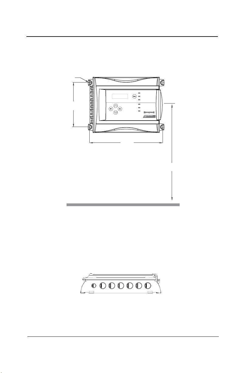
17.4 cm
6
13/32”
26.8 cm
10
9/16”
1.5m
5’
Ø .5cm
¼”
Installation Instructions
Surface Mount Installation
It is recommended that controllers be installed 5 feet (1.5 m) above the
floor, at approximate eye level.
Mark the holes as shown:
• Height markers 6 13/32” apart
• Width markers 10 9/16” apart
• Pre-drill 1/4” mounting holes as needed
• Securely mount the 301C using the appropriate screws
Wiring for the unit must be passed through the knock-outs provided at
the bottom of the unit.
M-510324 301C User Manual 13
7/10 Honeywell
Page 16
Introduction
COMMUNICATION
Communication Wire Gauge:
2-24 AWG (Belden 9841)
Twisted and shielded cable
2000 feet (600 m) per channel
T-tap: 65 feet (20 m) / T-tap
130 feet (40 m) total
Channel Specifications :
Channel 1-2: Modbus,Vulbus protocol
Channel 3: Modbus protocol only
Communicates only with Vulcain
transmitters
Channel 4: Modbus output
Communicates only with VA301 BDCM
Channel 4 (not used)
Channel 3
A 4
B 4
A 3
B 3
Channel 2
Channel 1
B 2
A 2
A 1
B 1
V-
NEXT
V+
PREVIOUS
V-
V+
5(6(7
3&%&:5$
6+,(/'
6+,(/'
6+'1
9
%$%$
%$
5,*+7
/()7
5;
7;
$/$50B$
%
$
9
$/$50B%
$/$50B&
32:(5
)$8/7
'2:1
(17(5
(6&
6,/(1&(
1&
12
12 1&
83
0$'(,1&$1$'$
5&
5&
5&
5&
5
5
5
5
5(/$<
5(/$<
5(/$<
5(/$<
9LQ 9RXW
(7+(51(702'8/(
99
-
-
-
-
-
5
/('
/('
/('
/('
/('
&
6:
6:
6:
6:
6:
6:
/('
/('
/('
/('
/('
/('
/('
.
-
-
-
(2/
(2/
(2/
(2/
%=
-
-
-
-
-
-
-
.
.
/
5
-
6:
-
.
0DGHLQ&DQDGD
9XOFDLQ,QF
9$&:35%
5(6(7
-
-
'
'
-3
/
1&
12
12
Ethernet: 10/100-compa tible with 10Base-T
interface, RJ-45
Visual Indicators:
Green LED LINK
Yellow LED ACT
BacNet/IP MODULE (-BIP option)
Always respect minimum
voltage requirements at device
LCD screen
Wireless
communication module
Wireless Communication :
ISM worldwide
Indoor range 30m
RELAY OUTPUTS
3+5
4+6
1+3
2+4
Normally
open
Normally
closed
5
31
642
RISK OF ELECTRIC SHOCK
RISK OF ELECTRIC SHOCK
End-of-line specification :
The E.O.L. jumper for
channels 1-2-3-4 must
always be in E.O.L.
position.
End-of-line jumper
position
5&
5
SD Card
Grounding screw
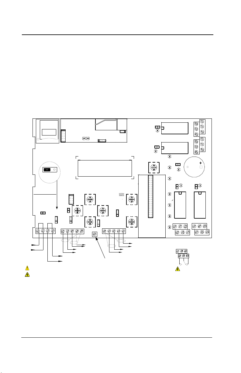
Wiring Details
Wiring Details
The diagram below provides the details required to connect the 301C
with the wireless communication module (coordinator). This module
allows the controller to communicate with and manage the 301W
wireless gas detectors.
Details concerning power supply, cables, capacities, etc., are provided
in the Specifications section at the back of this manual.
14 301C User Manual M-510324
Honeywell 7/10
Page 17

Introduction
Wiring Details
The connectors, or ports, on the PCB allow various wiring to be
connected to the controller. The wiring includes power, communication,
BACNet and relays, each with an assigned position (and number) on
the board:
J22 Power Input: Connect the power supply to the controller
(see Wiring Details for cabling diagrams)
J23, J24 Communication
inputs: Connect communication cables to channels 1
through 3.
Relay Outputs 1-4: Depending on the desired configuration,
connect the relay cables to either N.O. or N.C.
SHDN jumper Place the jumper over the Shutdown header
pins to reset or restart the system.
EOL Resistors 1-4: Place the jumper over the header pins to
create the connection to attenuate
communication echoes.
M-510324 301C User Manual 15
7/10 Honeywell
Page 18

Introduction
Power Connections
Power Connections
The 301C requires a power range of 17-27 Vac, 50/60 Hz (8.64 VA),
18-36 Vdc, 350 mA @24 Vdc (8.4 VA). Polarization is not important in
either AC or DC mode. The system must be grounded on the
transformer and a dedicated circuit breaker must be used.
Communication Connections
Communication cables must be grounded using the shield terminal,
using twisted and shielded pair Belden 2-24 AWG #9841 cable (or
equivalent).
The network cabling can extend up to a limit of 2000 feet (609 m) per
channel.
The length of a T-tap can reach 65 feet (20 m), up to a maximum of 130
feet (40 m) for all T-taps.
All wireless devices associated to the controller will automatically be
detected and communicate with the controller using wireless
communication protocols.
Settings for Specific Transmitters
Honeywell Sensepoint XCD Transmitters must be configured for 9600
baud, no parity, and a unique address. Honeywell XNX Universal
Transmitters must be configured for 9600 baud and a unique address.
Information on configuring each transmitter is in the associated
technical manual.
16 301C User Manual M-510324
Honeywell 7/10
Page 19

Introduction
RELAY OUTPUTS
N.O.
N.C.
COMM
Normally closed
Normally open
Relay Output
Relay Output
The relay output can withstand up to 5A at 30Vdc or 250Vac (resistive
load only). Relays can be used to activate horns and strobes. Although
each relay is programmed with a default setting (below), they can be
configured using the controller programming menu.
If relays are set to Normally closed, the relay is powered up with the
controller and the device linked to the relay is functioning. The relay will
shut down when the specified alarm condition is reached.
If the relay is set to normally open, the relay will remain off when the
controller is powered up and the device connected to the relay will only
be activated when the specified alarm condition is reached.
Note: These functions are reversed if the controller Failsafe mode has
been activated.
M-510324 301C User Manual 17
7/10 Honeywell
Page 20

Relay Output
Jumper Use Instructions
The jumpers on the controller PCB allow a variety of operations to be
performed manually:
EOL 1-4: Enables the user to add End-Of-Line jumpers that improve
communication signals. Put the jumper in R position (as
shown on wiring diagram) to activate the End-of-Line
termination. (R provides a resistance termination and RC
provides resistance and condensator termination.)
SHDN: Enables the microcontroller to be reset or temporarily shut
down. This function is used mainly when system wiring
adjustments are needed (power off for safety).
Relays These jumpers allow the relay to be tested by activating it
J29-J32 without having any effect on Events.
18 301C User Manual M-510324
Honeywell 7/10
Page 21

Getting Started
Relay Output
Getting Started
The controller units are customized to the purchaser’s specifications but
they can be further programmed using the following menu options.
Initial Startup
Make sure that all wiring has been completed according to
specifications in the wiring details before powering up the unit. When
all is secure, remove the SHDN jumper to power-up the unit. It should
only take a few seconds until the unit is fully operative.
Datalogger (SDcard)
The DLC (Data Logger Card) option for the controller collects data and
stores it on a digital Flash memory card (SDCard). In the event that the
card memory becomes full:
• Information logging is stopped
• No SDcard flag is displayed on-screen
• The SDcard LED blinks
See the Acquisition section for more details on starting and stopping the
datalogging function.
CAUTION
M-510324 301C User Manual 19
7/10 Honeywell
Always deactivate datalogging function before removing the
SDcard. Never remove the card when its LED is on.
Page 22
Getting Started
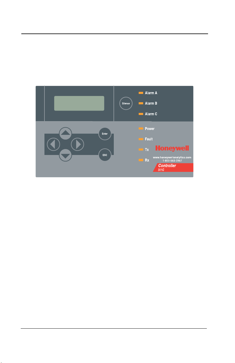
Programming Interface
Programming Interface
The front panel of the 301C provides a programming keypad (buttons)
and LEDs.
301C front panel Keypad
Keypad Functions
Each unit has 7 keypad keys, or buttons:
Arrows: Used to move the cursor through the various programming
fields (Up, Down, Left and Right), or to adjust the display
contrast (press and hold the up or down arrow until desired
contrast is reached and release).
ESC: Used to exit the programming menu or to cancel a change or
input.
Enter: Used to access the programming menu and to modify
programming fields.
Silence: Turns off the controller’s buzzer.
20 301C User Manual M-510324
Honeywell 7/10
Page 23

Getting Started
Programming Interface
LED Definitions
The controller is equipped with 7 LEDs that provide a status for each
function related to that indicator:
Alarm A: A blinking red light indicates that an event has been
activated. A constant red light indicates that one or more
transmitters has reached Alarm A or Alarm 1.
Alarm B When the red indicator is on, one or more transmitters has
reached Alarm B or Alarm 2.
Alarm C When the red indicator is on, one or more transmitters has
reached Alarm C.
Power: Green indicates that the unit is powered up and functional
Fault: When the amber LED is on, it indicates a fault (i.e. a
communication, maintenance or device problem)
Tx: When the amber LED is blinking, it indicates that the
controller is sending information or requests on the
communication channel.
Rx: When the green LED is blinking, it indicates that the
controller is receiving information.
Each of these functions is linked to parameters programmed in the
control unit, which we will discuss in the following section.
System Operation
The system operates in four different modes that allow it to use,
analyze, debug, and simulate the actions that the system can perform.
These modes are: Normal, Single Tx, Debug and Simulate. The default
system operation mode is Normal. The other modes are available
through the Tests menu (option 8 from the Main Menu).
Note: Systems services may be disrupted by some menu operations.
M-510324 301C User Manual 21
7/10 Honeywell
Page 24

System Programming
VA301C Ver. 3.00
Ad: 1 Gr:0 Ev:0
2007-01-17 13:18:18
Programming Interface
System Programming
The system’s Normal programming mode offers several menu options
that are accessible from the main menu screen:
Tx Info: Allows transmitter parameters to be programmed
Groups: Allows groups of transmitters to be set up
Events: Allows events and event behavior to be programmed
Acqui: Allows the datalogging feature to be activated or deactivated
Copy: Allows data or parameters to be copied from the (controller)
configuration to parameters
Config: Allows system parameters and password to be set
Network: Allows actions on the network to be performed,
communication statistics to be consulted, and remote
calibrations to be performed
Tests: Allows each device to be tested sequentially (inputs, outputs,
communications, events, etc.) and operation of various
parameters to be validated
BACNet: Allows a device’s BACNet parameters to be set
Wireless: Allows a network of wireless gas detection devices to be
configured, monitored, and modified.
Note: Access to the programming functions is password protected.
The default password is 2967.
The screen display shown below appears initially. This display can be
configured to scroll among the information screens for each device
connected to the controller.
If one or more of the connected devices is in an alarm mode, the
controller will only scroll between the main information screen and the
screens for device(s) in alarm mode. In this case, you must scroll
manually to view screens for other devices.
22 301C User Manual M-510324
Honeywell 7/10
Page 25

System Programming
Programming Interface
The information screen also displays icons representing certain system
functions. Here is a list of possible icons and their meaning:
Icon Description
BACNet: Indicates that there is a BACNet module present
and that it is communicating with the controller.
BACNet error: Indicates that a BACNet module is present
but communication with the controller has failed (error)
Debug: Indicates whether the controller is in debug mode
(Single TX, Debug or Simulation modes). When in
simulation mode, SIM appears next to this icon.
Log: Indicates that either “Tx Logging” or “Event logging” is
enabled.
Log error: Indicates that an error occured during TX or
Event logging. All logging functions are stopped.
SDC: Indicates that an SDcard is present and functionning.
The icon “fills” (from white to black) progressively as
memory is used. A white icon indicates empty memory
and black indicates full memory.
SDC error: If this symbol persists for more than 5 seconds,
an SD card card is present but not functioning properly.
Wireless network: Indicates that the wireless network
coordinator (wireless communication module) is present
and communicating with the controller.
Wireless network error: Indicates that the wireless network
coordinator (wireless communication module) is present
but is not communicating with the controller.
M-510324 301C User Manual 23
7/10 Honeywell
Page 26

System Programming
PASSWORD
_ _ _ _
MENU
1. Tx Info 3. Events
2. Groups 4. Aqui
MENU
5. Copy 7. Network
6. Config 8. Tests
MENU
9. BACNet
10. Wireless
Programming Interface
Since the controller’s programming functions are password protected, it
is necessary to access the login screen:
• Press Enter to access the programming options. The password
screen appears:
• Use the keypad Up or Down arrows to increase or decrease the
value, one digit at a time, starting with the first digit
• When all the digits of the password are correct, press Enter to
access the programming functions.
The first MENU options screen appears. Use the keypad arrows to
navigate through multiple screens to the desired function and press
Enter to access it.
24 301C User Manual M-510324
Honeywell 7/10
Page 27
System Programming
Tx Info Menu
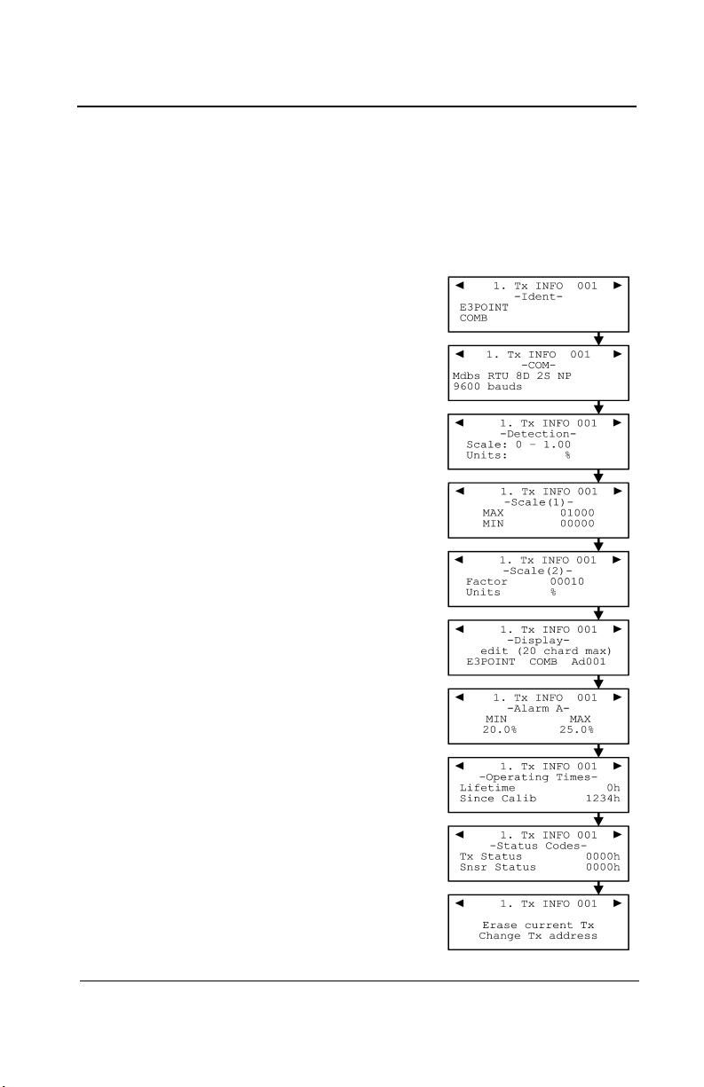
Tx Info Menu
Tx Info is the menu option that is dedicated to transmitter information
and contains several sub-menu options. The exact list of screens will
vary depending on the transmitter type. A summary is presented below
with details on the following pages
Ident: Allows the network component’s
identification information to be
viewed.
COM: Allows the communication
protocol to be viewed or changed
Detection Allows the detection range and
or Scale(1) the unit of measurement
and parameters to be viewed and
Scale(2): changed
Display: Allows the label (or name) of a
specific component to be
changed
Alarms: Allow alarm thresholds to be
viewed and sometimes changed.
There can be significant
variations in this screen
depending on transmitter type.
Status Transmitter and node status
Displays: (in hexadecimal values)
Erase or Erases or changes the
Current Tx: Tx address
M-510324 301C User Manual 25
7/10 Honeywell
Page 28

System Programming
1. Tx Info 001
-IdentNotVul
CO2 (IR)
Tx Info Menu
Ident Menu
The Ident, or identification menu allows a component’s network ID to be
consulted:
The upper right corner of the screen shows the component’s address. If
the address of the device whose information must be viewed is known:
• Use the arrows to move the cursor arrow to the on-screen address
• Press Enter (the value can be edited while the number is flashing)
• Use the up or down arrows to increase or decrease the value
• Press Enter again to validate the entry and display the information
for the desired device.
The bottom left corner of the display shows the transmitter name (ex.:
301D2 - product name) and the sensor type (ex.: CH4 - methane
sensor). These values can also be changed for Group or Vulbus
product types. The procedure is identical for both fields:
Programming or changing a product or sensor type
• Use the arrows to move the cursor to the product type field.
• Press Enter to select the field (the value can be modified when
flashing)
• Use the arrows to scroll through the list of product types and press
Enter when the desired product or sensor appears
26 301C User Manual M-510324
Honeywell 7/10
Page 29

System Programming
1. Tx Info 121
-Ident301W
CO2 (IR)
Tx Info Menu
Product and Sensor Types
This is a list of all the (preprogrammed) product types available from the
Identification option in the Tx Info menu.
The order of the products below is not necessarily the order in which
they will appear in the controller
Product Types
Addresses 1-96
VA301D2 VA301AP XNX
90DM3R VASQN8X XCD
VA301IRF VA301EM VA201R
IRT100 VA301EMRP VA201T
EC-F9 GsPnt2 90DM2
VA201T2 S301RLC VA201D
VA301T (Std.Device)* VA301D
GsPnt VA901T NotVul
RgRt3
Product Types
Addresses 97-120 Addresses 121-170
301ADI (?)
(?) 301W
301RW
301RPT
* E3Point and 420MDBS are examples of standard devices.
Note: When Group is selected as a product type, the remaining Tx
INFO screens are not accessible (because each product in the
group has already been individually programmed). Only the Ident
and Erase current Tx screens will be available.
M-510324 301C User Manual 27
7/10 Honeywell
Page 30

System Programming
Tx Info Menu
The sensor type list applies to address ranges 1-96 and is not
dependent on the type of product selected. Devices in the address
range from 97-170 will display a BACNet object identifier, rather than a
sensor type.
*An additional Product Type, simply called “Group”, represents a group
created in the Groups Menu in the controller. When scrolling through
the available product type list, this name will appear as many times as
there are groups created in the controller (example: Group 1, Group 2,
Group 3, etc.). If a group is selected as the product type, then the
sensor type options are limited to MIN, MAX and MEAN.
28 301C User Manual M-510324
Honeywell 7/10
Page 31

System Programming
1. Tx Info 001
-COM-
Mdbs RTU 8D 1S EP
9600 bauds
1. Tx Info 001
-COMMdbs RTU 8D 1S EP
9600 bauds
Tx Info Menu
COM Menu
This screen displays the selected communication protocol for device
addresses from 1 to 96. Each transmitter’s protocol is defined by the
controller (see Network Auto-configuration section)
.
If a transmitter is compatible with several different protocols, it can be
modified using to one of the following options:
•Vulbus
• Mdbs ASCII 7D 2S NP 9600 bauds
• Mdbs RTU 8D 2S NP 9600 bauds
• Mdbs RTU 8D 1S NP 9600 bauds
• Mdbs RTU 8D 1S OP 9600 bauds
When a transmitter is configured with the Modbus communication
protocol, the transmitters automatically sends the programmable
parameters to the controller.
Note: Vulbus transmitter parameters must be programmed manually.
M-510324 301C User Manual 29
7/10 Honeywell
Page 32

System Programming
1. Tx Info 001
-Scale(1)-
Max 00250
Min 00000
1. Tx Info 001
-Scale(2)-
Factor 00010
Units %
Tx Info Menu
Scale Menus (1 and 2)
These menus appear only for certain devices. Scale(1) allows the
detection range, minimum and maximum, to be defined for the selected
device. Whatever value is specified is the value that will appear at the
device display (if applicable). The Minimum value is generally left at 0.
Parameters for the XNX and XCD gas detectors can be viewed here
but can be changed only at the transmitter.
Scale(2) allows the factor by which to divide the scale (between 0 and
65535) and the unit of measurement for the selected scale to be
determined.
The factor allows precise scale limits for detection to be set. By dividing
the maximum scale value in the first Scale screen (250 in this example)
by 10, a scale value of 25.0 can then be displayed.
The “Units” allow the unit of measurement for the device to be selected:
°F: Sets degree Farenheit as the unit of measurement
°C Sets degree Centigrade as the unit of measurement
%RH Sets Relative Humidity as the unit of measurement
mV Sets millivolts as the unit of measurement
V Sets volts as the unit of measurement
mA Sets milliamps as the unit of measurement
% Sets the percentage of gas as the point unit of measurement
ppm Sets parts per million of gas as the point unit of
measurement
30 301C User Manual M-510324
Honeywell 7/10
Page 33

System Programming
1. Tx Info 001
-Detectionscale: 0-0.00
unit: %
Tx Info Menu
Detection Menu
The detection menu (available only for devices with addresses between
1 and 96) displays the detection range (scale: 0-100.0) and the unit of
measurement (unit: %) for the selected component. If a transmitter
uses the Modbus protocol, the detection parameters are automatically
defined during network configuration and are not editable. Vulbus
protocols must be manually defined by the programmer.
The detection scale is between 0 and the maximum value (0.00) and
the unit of measurement is either ppm or percent (% for oxygen and %
LEL for combustibles).
The detection menu is not available for the VA301R or VA301AP.
Programming or modifying the scale range or unit:
• Use the arrows to move the cursor to the scale or unit option
• Press Enter and use the arrow to increase or decrease the value
• Press Enter when the desired value is obtained
M-510324 301C User Manual 31
7/10 Honeywell
Page 34

System Programming
1. Tx Info 001
-Display-
edit (20 char.max)
301D2 CH4 Ad001
Tx Info Menu
Display Menu
This option allows a specific label or name to be assigned to the
selected component (transmitters, relay modules, annunciators). Up to
20 characters, including spaces, can be used in the label (example:
BOILER ROOM). The default Modbus transmitter labels are composed
of the component (or transmitter) name, sensor type and address.
Vulbus transmitter labels contain 20 blank characters (spaces).
32 301C User Manual M-510324
Honeywell 7/10
Page 35

System Programming
Tx Info Menu
Alarm A, B and C Menus
The screens for viewing alarm thresholds are combined in this manual.
There will be either two or three levels, depending on transmitter type.
If present, separate “MIN” and “MAX”levels permit manual control of the
hysteresis of each alarm. Normally, the “MAX” level is set greater than
“MIN.” However, alarms can be made to trigger on falling concentration
(as with oxygen) by setting the “MAX” threshold smaller than the “MIN”
threshold.
With certain transmitters, only one threshold will be displayed.
Additionally, with certain transmitters, the alarm thresholds are readonly at the controller. These thresholds can be set only at the
transmitter.
These are typical screens:
Typical screen for viewing alarms A or B on XCD and XNX transmitters
Typical screen for viewing or changing alarm A, B, or C thresholds on
other transmitters.
M-510324 301C User Manual 33
7/10 Honeywell
Page 36

System Programming
Tx Info Menu
Servicing and Operating Menus
These functions vary depending on the transmitter type. These displays
show the total time the device has been in service and the amount of
time remaining until the next required calibration or replacement.
34 301C User Manual M-510324
Honeywell 7/10
Page 37

System Programming
1. Tx Info 001
erase current Tx
Change Tx Address
Tx Info Menu
Status Code
These screens display transmission or node status and sensor status
for the selected transmitter. This read-only information can assist
service personnel in troubleshooting.
The XNX and XCD gas detectors will report the warning or fault number
(iFaultWarnNumber) in hexidecimal on the third line. These transmitters
will also report the monitoring state (iMonitoringState) in the fourth line.
See the transmitter documentation for interpretation of fault numbers
and monitoring states.
Typical display for XNX or XCD
Typical display for other transmitters
Erase Current Tx
This function allows the configuration to be erased or the Tx address for
the displayed component to be changed.
Note: Selecting erase current Tx only erases the current device entry
Tx Info configuration. No other data is erased.
M-510324 301C User Manual 35
7/10 Honeywell
Page 38

System Programming
1. Tx Info 001
erase current Tx
Change Tx Address
1. Tx Info 001
To address: 001
1. Tx Info 001
Processing...
Tx Info Menu
Change Tx Address
Selecting Change Tx Address allows users to move a device from one
TX address to another:
• Use the arrows to scroll to Change Tx Address and press Enter to
select
• In the next screen, scroll to the address number and press Enter to
select
• Use the up or down arrows to increase or decrease the address
value and press Enter to validate the new address.
The Change Tx address option is only available (active) for device
address 1 to 96 and if there is a Modbus device connected.
If the address is valid, the screen will display “Processing”.
If the address is invalid, the screen will display “Invalid Tx” and return
to the Change Tx Address screen (the address for GasPoint devices
cannot be changed)
A final screen will display either “Error” or “Success” (re-start procedure
if Error is displayed).
Note: If a device address is changed to one already associated with
another device, the existing data will be overwritten. Customers
should know their network’s address assignments and be careful
when changing a Tx address. Delete the original Tx address to
avoid duplicate entries.This feature is not supported with XNX
and XCD transmitters.
36 301C User Manual M-510324
Honeywell 7/10
Page 39

System Programming
MENU
1. TxInfo 3. Events
2. Groups 4. Acqui
2. Groups 001
<end> [----] [----] [----]
[----] [----] [----] [----]
empty all groups
Groups Menu
Groups Menu
Programming groups of transmitters allows several units to be
combined which then enables actions (events) to be taken based on a
series of units rather than each unit, individually.
A group is a stack containing the addresses from each of the
transmitters included in the group.
Groups are displayed in a single line; if a group contains more than four
components, the arrows must be used to scroll left and right of the
display window to view all members of a group.
The cursor in the Group screen is represented by the blinking brackets
(<end>). Any information between the brackets can be edited.
M-510324 301C User Manual 37
7/10 Honeywell
Page 40

System Programming
Groups Menu
Creating Groups
• Use the arrows to move the cursor to a group line and press Enter
• The field can be edited when the brackets stop blinking and the
word “end” blinks
• Use the up or down arrows to scroll through the list of all units
connected to the 301C, until the desired address is displayed .
• Press Enter again to validate the address.
• The address is added to the group and the <end> bracket is
shifted one position to the right.
The process can be repeated until all the desired transmitters in the
group (up to 126) have been added. The address for each transmitter
added in the Tx Info menu is available when creating groups.
Note: Groups created in the Groups menu will appear in the product
type list (Tx Info - Ident screen) as “Group xx” (the number
assigned to the group when it was created).
38 301C User Manual M-510324
Honeywell 7/10
Page 41

System Programming
Groups Menu
Deleting Groups
Use the empty all groups command to delete all groups previously
programmed in the controller.
Single groups can be deleted with a simple procedure:
• Scroll to the first transmitter in the group list,
• Select the transmitter (its address blinks) and scroll to <del> (<del>
erases the entry and <end> marks the end of the stack)
• Press enter and the group is emptied.
This procedure makes it possible to delete one, several or all entries
previously included in a group.
Note: Up to 126 groups, with a maximum of 128 members each, can be
created.
7/10 Honeywell
39
Page 42

System Programming
Event Menu
Event Menu
Though the controller has a default setting for Event configuration (as
shown below), the Event menu is programmable. Event programming
lets specific actions to be defined:
Action: What will be done if programmed criteria are reached
Delay: Defines the length of time to wait before taking an
action on an event and time to wait after an event
has returned to normal before the action output is
returned to normal state.
Conditions: AND, OR or none (---); equations that allow more
detailed control of an event
Coverage Determines the period during which the event is
period: applicable
Status: Disables or enables a programmed Event
disabled:
Database: Erases the selected event or all events
40 301C User Manual M-510324
Honeywell 7/10
Page 43

3. Events 001
-DelaysBefore: 99min
After: 01min
3. Events 001
-Action-
Target: Ctrl
Relay: #01
3. Events 001
1/3 Gr036
=2.01% AND
3. Events 001
-Coverage PeriodAll day
All week
3. Events 001
-DatabaseErase current event
Erase all events
3. EVENEMENT 001
-Status : disabledEnable event
.
System Programming
Event Menu
M-510324 301C User Manual 41
7/10 Honeywell
Page 44

System Programming
3. Events 001
-ActionTarget: Ctrl
Relay: #01
Event Menu
Action Menu
Actions are comprised of two parameters:
Target Indicates which component is responsible for the action to
be taken;
Tx (transmitter)
Re (Relay/Annunciator)
Ctrl (Controller)
Relay Indicates which of three possible outputs will be activated
when the event is true;
#XX (activates the component’s #xx relay), Buzzer (activates
the component’s audible alarm)
ALL (activates the relays and audible alarms)
Example: Tx 007 detects a concentration exceeding the set values.
The target (controller) triggers relay 1 connected to that event (a fan
perhaps).
42 301C User Manual M-510324
Honeywell 7/10
Page 45

System Programming
3. Events 001
-Delays-
Before: 99min
After: 01min
Event Menu
Delays Menu
This option allows Before and After settings that will delay the activation
or deactivation of an action to be programmed.
Before Delays the action for the specified length of time. If the
condition persists beyond this delay, the defined action is
executed.
After The time to wait after an event has returned to normal before
returning action output to normal state. The after delay also
offers a Latch option, described below.
Before and After delays can be configured at either 30 or 45 seconds or
from 1 to 99 minutes, in one minute increments. Five dashes (-----)
indicates that no delay has been programmed.
• Use the keypad arrows to scroll to the desire option
• Press Enter to select the option
• Use the keypad arrows to scroll through the second or minute
settings
• Press Enter at the desired setting. The delay is set.
M-510324 301C User Manual 43
7/10 Honeywell
Page 46

System Programming
Event Menu
Latch Mode
• The Latch function is executed on an Event state
• It is possible to select the Latch mode by changing the after delay
to “ ”
• The Event stays active until the Silence keypad button is pressed
• The Silence keypad button has two functions: Silence the buzzer
and unlatch the event.
• When the Silence keypad button is pressed, events in Latch mode
are unlatched and reevaluated. If the Event condition persists, the
Event remains active and returns to Latch mode. If the condition
does not persist, the event is deactivated.
Note: If the Event has a Before delay and the Silence button is pressed
while the Event conditions are still true, the buzzer will be
silenced only for the length of the programmed delay.
44 301C User Manual M-510324
Honeywell 7/10
Page 47

Event Menu
3. Events 001
1/3 Gr036
>2.01% AND
3. Events 001
all Gr003
AND > 2.99%
Conditions
Conditions are the parameters that define what makes an Event true.
Each condition is defined by four elements and can be combined with
other conditions to provide greater flexibility. A condition, as in the
example provided below, defines:
IF at least 1/3 of group 36 detects concentrations greater than 2.01% of
specified gas AND all of group 03 detects a concentration greater than
2.99% of gas, then the specified action (Actions were set at the first
Event screen) for that Event will be triggered.
Since the display screens offer limited space, scroll left and right to view
and edit further information.
Condition programming screens
The portion of the Events condition screen that is within the brackets is
divided into four editable list fields:
7/10 Honeywell
45
Page 48

System Programming
Event Menu
The top left portion contains the statistic quantifier (available only for
Groups) that take only the specified part of the group into the equation.
Options available in this field are:
all: includes all transmitters in the group
mean: includes the average concentration for the group’s transmitters
max: includes the group’s maximum concentration
min: includes the group’s minimum concentration
1/4: includes at least a quarter of the group’s transmitters that
meets set conditions
1/3: includes at least a third of the group’s transmitters that meets
set conditions
1/2: includes at least half of the group’s transmitters that meets set
conditions
2/3: includes at least two thirds of the group’s transmitters that
meets set conditions
3/4: includes at least three quarters of the group’s transmitters that
meets set conditions
1 or +: at least one or more than one of the group’s transmitters that
meets set conditions
46 301C User Manual M-510324
Honeywell 7/10
Page 49

System Programming
Event Menu
The bottom left portion contains the logic, or operator, quantifier that
determines how conditions are calculated. Options available in this field
are:
Operator
Symbol
--- No operator
= Equal to
<= Equal to or smaller than
< Smaller than
>= Equal to or larger than
> Larger than
!= Not equal to
max
min
When the maximum value is reached, an action is triggered. It
will not be deactivated until levels fall below minimum value
When concentrations fall below minimum value, an action is
triggered. It will not be deactivated until concentrations rise
above set maximum value
Meaning
The top right portion contains the source, which defines what device or
group of devices the Event will be based on. The list provides the
following options:
GrAll: Includes all transmitters (see note)
Gr_ _ _: Includes only the devices in the specified group (see note)
Tx000: Includes only the specified transmitter (connected to the con-
troller)
Clock: Includes only information gathered between the specified
times. Selecting clock sets a condition that is applied only
between the start and end time frame. It is possible to set
one condition screen to specific parameters and the second
to clock, which means that the specified condition will trigger
an event only if it occurs during the set time period.
Note: Clicking on the magnifying glass to the right of a Group number
on the display opens a view of the Group for consultation or
editing. Press Esc to close the group view and return to the
Event condition screen.
M-510324 301C User Manual 47
7/10 Honeywell
Page 50

System Programming
3. Events 001
-Coverage PeriodAll day
All week
Event Menu
The bottom right portion contains the operand, which defines what
device or group of devices on which the Event will be based. The list
provides the following options:
OFF Used for status on binary inputs (ex.: used with 301ADI)
ON: Used for status on binary inputs (ex.: used with 301ADI)
Fault: Bases trigger on maintenance alarm, communication failure or
device failure
Alrm A: If the chosen device or group has an Alarm A or Alarm 1, an
event will be triggered.
Alrm B: If the chosen device or group has an Alarm B or Alarm 2, an
event will be triggered
Alrm C: If the chosen device or group has an Alarm C, an event will be
triggered.
The Coverage Period screen allows the period that will be covered by
the Event to be defined. (The time frames for each of these periods
can be defined in the controller Config menu.) This option provides two
further selection fields:
Day definition field: allows All day, Daytime, or Nighttime to be selected
Week definition field: Weekend, Working Days, All week
1. Use the keypad up or down arrows to scroll to either All day or All
week
2. Press Enter to select. The value can now be changed
3. Use the keypad up ro down arrows to scroll through options (see
above)
4. Press Enter to select.
48 301C User Manual M-510324
Honeywell 8/10
Page 51

System Programming
3. EVENT 001
-Status : disabledEnable event
.
3. Events 001
-DatabaseErase current event
Erase all events
Event Menu
Status
This screen displays the current event status and allows it to be either
enabled or disabled, depending on the current status.
Enable event:This is a “toggle” switch; press Enter to change the value
from Enable to Disable and vice versa
After going through all the steps and programming an event, this screen
will display “Enable event”. Press Enter to activate all the parameters
and enable the Event.
If an existing Event is being consulted, this screen would display
“Disable event”. Press Enter to disable an Event (it will not be deleted
but will not function). The programming of this Event is always present,
which means that it easily can be reactivated by scrolling to this screen
and pressing Enter.
Database
This screens displays the options linked to the database:
Erase current event:Lets user erase the current event
Erase all events:Lets user erase all events
M-510324 301C User Manual 49
7/10 Honeywell
Page 52

System Programming
4. Acquisition
10% threshold mode
Start Tx logging
Start event logging
2005-04-27 11:05:20;1_CO2_ppm;574;-normal-:
2005-04-27 11:06:02;1_CO2_ppm;503;-normal-:
2005-04-27 11:06:15;1_CO2_ppm;562;-normal-:
2005-04-27 11:06:28;1_CO2_ppm;645;-normal-:
2005-04-27 11:06:39;1_CO2_ppm;557;-normal-:
2005-04-27 11:30:45;1_CO2_ppm;715;-normal-:
Acquisition Menu
Acquisition Menu
The Acquisition mode is only accessible when there is an SD card
present (controllers with the Data Logging, or DLC function). It is used
to enable or disable the logging of system Events or transmitter
information. The information is logged (or recorded) on an SD card.
Intervals or conditions must be defined before using this option.
The first line of the Acquisition screen offers either :
Delay mode: Allows for delay intervals of 10 to 59 seconds
or 1 to 60 minutes.
Threshold mode: Allows log values to be set according to set
variation thresholds (based on last reading) of
3% or more, 5% or more or 10% or more of
last detected concentration.
If a 3% threshhold is selected, the system will not log a value at 3% but
will log a value of 3.1%. Remember that the sampling rate (system
refresh rate) may have an impact on logging.
Here is an example of threshold logging. The logs a semi-colon
delineated text files.
50 301C User Manual M-510324
Honeywell 7/10
Page 53

System Programming
2004-01-23 17;54;25; 001_CO_ppm;0;-normal-;002_NO2_ppm;1.5;-normal-;003_CO_ppm;0;-normal2004-01-23 17;55;25; 001_CO_ppm;0;-normal-;002_NO2_ppm;0.5;-normal-;003_CO_ppm;0;-normal2004-01-23 17;56;25; 001_CO_ppm;0;-normal-;002_NO2_ppm;0.5;-normal-;003_CO_ppm;0;-normal2004-01-23 17;57;25; 001_CO_ppm;0;-normal-;002_NO2_ppm;1.0;-normal-;003_CO_ppm;0;-normal2004-01-23 17;58;25; 001_CO_ppm;0;-normal-;002_NO2_ppm;1.5;-normal-;003_CO_ppm;0;-normal-
Acquisition Menu
Starting and Stopping Tx Logging
In the previous step, “Acquisition”, the frequency at which Tx logs would
be recorded can be configured. To start the logging function:
When “Start Tx logging” appears on the display, it indicates that the
acquisition, or logging, mode is inactive. When “Stop Tx logging”
appears, it indicates that Tx data is being logged. The log message is
displayed on the screen according to the chosen mode and LED 1 will
light up.
Press the Enter keypad button to stop or start Tx logging.
When Tx data is logged, the system creates files named
tayymmdd.log, tbyymmdd.log and tcyymmdd.log, each representing
one third of the network. The record includes the transmitter’s date,
time and address, the sensor type, the concentration read, as well as
the alarm status. Here is a sample of what a Tx log looks like:
The first column of the Tx log displays the date (yyyy-mm-dd) and the
time (hh:mm:ss) of the log. In this example, the “Delay mode” was set
to one minute intervals.
The third column of the Tx log displays the transmitter address and the
fourth displays the gas type, gas concentration and unit of
measurement.
The display then lists the next transmitter address with its gas type,
concentration and unit of measurement, and so on until all the
transmitters have been listed.
M-510324 301C User Manual 51
7/10 Honeywell
Page 54

System Programming
2004-01-23 17:54:25: Event logging enable
2004-01-23 17:55:25: Event logging enabled
2004-01-23 19:05:47; Simulation sequence activated
2004-01-23 19:05:48; Tx 6 communication no more in fault
2004-01-23 19:05:48; Tx 8 communication no more in fault
Acquisition Menu
Starting and Stopping Event Logging
The Acquisition menu offers an event logging option. Event Logging
records controller transactions, events, Tx and alarm flags and relay
status.
When “Start Event logging” appears on the display, it indicates that the
acquisition, or logging, mode is inactive. When “Stop Event logging”
appears, it indicates that Event data is being logged.
Press the Enter keypad button to stop or start Event logging.
When Event data is logged, the system creates a file named
evyymmdd.log. The record includes the date, time and the event.
Here is a sample of what an Event log looks like:
The first column of the Event log displays the date (yyyy-mm-dd) and
time (hh:mm:ss) of the log. Column A displays the date and time of the
log. In this example, the event’s “Delay mode” was set to one minute
intervals.
The system logs the following types of events:
• Event Log
• Event status changed
• Alarm A, B, C, Fault, and X status changed
Note: New log files are created when the existing files reach 32 000
lines or at the start of a new week (0h00 Sunday)
52 301C User Manual M-510324
Honeywell 7/10
Page 55

System Programming
5. Copy
-ConfigurationConfig to SDcard
SDcard to Config
Copy Menu
Copy Menu
The Copy menu allows programmed parameters to be copied and
transferred. Data from the SD card can be transferred to a controller or
from a controller to the SD card or copy parameters from one device to
the next. The Copy option offers three screens: Configuration,
Parameters and System Log.
Configuration
If the controller is equipped with an SD card, the configuration function
allows data to be transferred either from the 301C to the SD card or the
reverse. This makes it possible to transfer the controller’s programming
to a computer or from a computer to the controller.
The first option in the configuration screen is 301C to SDcard.
Selecting this option copies the controller’s configuration and
parameters into a “config.ini” file
1
.
The second option is SDcard to 301C allows the configuration and
parameters of the “config.ini” file on an SDcard to be copied to the
controller.
Note: The “config.ini” file contents can be modified at any time and from
any computer.
1. When transferring data, the system will automatically search for an existing “config.ini”
file before proceeding. If one exists, the system searches for a “config.bak” file. If
found, the file is deleted. Then, t he pre-existing “con fig.ini” file is r enamed “confi g.bak”,
making it possible to save the new “config.ini” fi le and keep a backup copy of the previous one.
After inserting an SD card into the controller, the controller’s system looks for an exist-
ing “config.ini” file that contains an “autoload” tag equal to 1 (yes). If the tag is found,
the system loads the contents of the file and reset s “autoloa d” to 0 (no). This is a useful
feature for editing the file on a computer without having any impact on the controller
(such as recorded Events).
M-510324 301C User Manual 53
7/10 Honeywell
Page 56

System Programming
5. Copy
-parametersTxInfo to TxInfo
Event to Event
TxInfo to TxInfo
source tx001
target tx113
COPY
Event to Event
source #001
target #013
COPY
Configuration
Parameters
The “parameters” function allows one transmitter’s configuration to be
copied to another or one event’s parameters to be copied to another
event. This allows several devices that share identical or similar
parameters to be quickly configured.
The options within this screen are:
Tx Info to Tx Info copies transmitter parameters from one device to
another.
Event to Event copies parameters from Event to Event.
The process is identical for both options:
• Select source, (the data to be copied) using the up/down keypad
arrows and press Enter.
• When the transmitter address is flashing, use the up/down keypad
buttons to search for the desired device address.
• Press Enter to select the new address
• Select the target address (where the data is to be copied to) in
exactly the same way as source
• Select COPY and press Enter. The parameters have been copied.
54 301C User Manual M-510324
Honeywell 7/10
Page 57

System Programming
5. Copy
-System Log-
SysLog to SDcard
--- START of system log dump : 2007-04-18 13:19:05 --2007-04-04 18:42:06;Accessing menu;
2007-04-04 18:43:47;Event 1 definition modified;
2007-04-04 18:48:12;Exiting menu;
2007-04-04 18:54:49;System power-down;
2007-04-04 18:56:40;System power-up;
2007-04-04 19:02:44;Accessing menu;
2007-04-04 19:03:07;Event 6 definition modified;
2007-04-04 19:03:21;Exiting menu;
2007-04-05 10:51:28;Accessing menu;
2007-04-05 10:54:59;Database reset;
2007-04-05 10:55:18;Tx 25 parameters modified;
2007-04-05 10:55:29;Group 0 definition modified;
2007-04-05 10:55:36;Group 0 definition modified;
2007-04-05 10:55:46;Group 0 definition modified;
2007-04-05 10:55:55;Group 4 definition modified;
2007-04-05 10:55:57;Exiting menu;
2007-04-05 10:56:02;Accessing menu;
2007-04-05 10:56:19;Tx 24 parameters modified;
Configuration
System Log Menu
The controller will record log information to its internal memory. If the
controller is equipped with an SD card, the system log function allows
users to save system log information to the memory card in text format.
When this option is selected, a log of all the last actions performed on
the controller is copied to the SDcard, with the filename slyymmdd.log.
This file can contain up to a maximum of 64Kb of information in text
format. Once the memory card is full, the oldest log entries are erased
and replaced by new entries.
Here is an example of a system log:
M-510324 301C User Manual 55
7/10 Honeywell
Page 58

System Programming
MENU
5. Copy 7. Network
6. Config 8. Tests
6. Config
Set User Password
- 2967 -
Slave Port Cnfg
6. Config
Relay Configuration
AP Brdcst: auto
Honeywell
6. Config
Day definition
Week definition
6. Config
Manual scroll mode
Set Date and Time
Menu français
Slave Port Cnfg
Address: 001
38400 bauds
Mdbs RTU 8D 2S NP
Relay Configuration
-FailsafeAll relays
Inactive
Relay Configuration
-Silence1234
dis ena dis dis
Day definition
-Daytimesta: 08:00
end: 17:00
Week definition
-Working Dayssta: Monday
end: Friday
Date and Time
2005-11-21 11:47:36
(ISO 8601 standard)
Config Menu
Config Menu
The Config menu contains several main configuration screens and is
used to program the controller display mode, adjust the date and time,
select the display language, change the controller access password,
modify the Slave Port configuration, set the Relay Configuration, and
select the AP Broadcast mode.
Each main screen offers further programming options, as shown.
56 301C User Manual M-510324
Honeywell 7/10
Page 59

Config Menu
6. Config
Manual scroll mode
Set Date and Time
Menu français
Date and Time
2005-11-21 11:47:36
(ISO 8601 standard)
Selecting the first line of the first screen allows selection from three
display modes: Manual scroll, 3-second scroll, 5-second scroll. If
Manual scroll mode is chosen, the screen will only advance if you press
on the arrow keypad buttons. If either 3 or 5 second scroll mode is
chosen, the screens will automatically scroll display readings for all
devices connected to the controller after 3 or 5 seconds.
3 or 5 second scroll modes do not prevent the keypad arrows to be used
to return to a previous screen or move ahead through the screens
manually.
Selecting the second line allows the date and time in a new screen to
be adjusted; Date and Time. When a number is flashing, the value can
be changed using the up/down keypad arrows. The year, month, day
and the hour, minute and second values can be changed.
The controller does not manage Daylight Savings Time, therefore,
users must manually adjust any time changes.
Selecting the third line allows the display language to be changed. If the
display is already in English, it will then display the Menu français option
(and vice-versa). Simply scroll to the line and press Enter to change the
language.
M-510324 301C User Manual 57
7/10 Honeywell
Page 60

Config Menu
6. Config
Set User Password
- 2967 -
Slave Port Cnfg
The second main screen in the Config menu allows a new user
password to be set and the slave port configuration to be modified.
The default password is 2967. Select Set User Password to change the
password:
• When the first digit blinks, change the value by using the up/down
keypad arrows to increase or decrease the number
• Use the left/right keypad arrows to move from one digit to the next.
• When the desired password has been set, press Enter to validate it
and exit the editing mode.
Note: Contact Honeywell technical support for help with lost passwords
at 1-800-563-2967.
58 301C User Manual M-510324
Honeywell 7/10
Page 61

System Programming
6. Config
Relay Configuration
AP Brdcst: auto
Honeywell
Relay Configuration
-FailsafeAll relays
Inactive
Relay Configuration
-Silence-
1234
dis ena dis dis
Config Menu
Scroll through the main Config menu screens using the left (previous) or
right (next) keypad arrows.
The third main screen in the Config menu allows the relay configuration
to be set, the AP broadcast mode and to select from four separate
manufacturers for the given controller.
When Relay Configuration is selected, two further options to configure
the relays are available: The first screen, Failsafe, appears allowing
the failsafe to be activated for all relays using the Enter keypad button.
This function is used in case of a power failure: if power is cut, the relay
will activate the connected device (ex. a light) to signal the problem.
Scrolling to the right displays the “Silence” screen that enables or
disables the silence option for each relay, using the Enter keypad
button.
M-510324 301C User Manual 59
7/10 Honeywell
Page 62

System Programming
6. Config
Day definition
Week definition
Day definition
-Daytimesta: 08:00
end: 17:00
Week definition
-Working Dayssta: Monday
end: Friday
Config Menu
The fourth screen in the Config menu allows a definition of a day and a
week to be programmed.
Day and Week definition allows hours (time frames) to be defined for
either Daytime and Working Days respectively.
Note: Remember, the controller uses a 24 hour clock (0:00 to 23:59).
Any time changes (DST) must be made manually or through
BACNet time synchronisation (BACNet module required).
60 301C User Manual M-510324
Honeywell 7/10
Page 63

System Programming
7. Network
Reset Database
Scan Network
Reset and Scan
Network Menu
Network Menu
The Network menu allows network device information to be either
scanned or reset.
This menu offers four options, divided into two screens; the first screen
contains three options:
Reset Database: Resets all network device Tx information in the
database. This only resets the Tx infomation
for the network device. It does not affect
programmed Groups or Events.
Network Scan: Begins an auto-detect of all network devices
that allows the system to configure the Tx
database for network devices (i.e. it will scan
and add new devices but will not overwrite or
erase the old database)
Reset and Scan: Performs both previous functions
simultaneously.
Note: Once one of these options has been set, wait until the controller
completes the process. Do not interrupt or stop the process once
it has begun.
M-510324 301C User Manual 61
7/10 Honeywell
Page 64

System Programming
7. Network
Statistics
Calibration
Statistics 001
Valid 16 100%
Errors 0 0%
Timeouts 0 0%
Network Menu
The second Network screen offers the Statistics and Calibration
options.
Selecting Statistics from the Network menu displays a screen
containing the statistics for the selected device address.
Valid: Indicates the number of valid responses for the last 16
requests
Errors: Indicates the number of errors in the response for the last 16
requests
Timeouts: Indicates the number of timeouts (no response) for the last
16 requests
62 301C User Manual M-510324
Honeywell 7/10
Page 65

System Programming
7. Network
Statistics
Calibration
Calib 007 S301M
Status: Normal
Set Zero
Set Span 246 PPM
Calib 007 S301M
Status: Normal
Set Zero
Set Span 246 PPM
Network Menu
Remote Calibration
The network menu also offers a Calibration option for use with devices
that support network calibration.
The Calibration screen contains four (4) lines of information:
Line 1: Indicates the mode (Calib, meaning calibration), the
(Modbus) address of the device to calibrate (001) and the
type of device to calibrate (301D2)
Line 2: Indicates the status (Normal or In calib…) of the specified
device
Line 3: Displays the function to perform (Set Zero)
Line 4: Displays the function to perform (Set Span) and the span
gas concentration value (246 ppm)
5. On the first line, scroll to the device address and press Enter
6. Scroll through the devices to display the desired device* and press
Enter to select.
7. The second line displays the device’s status
8. Scroll to select the desired function, Set Zero to set the device's
zero, and press Enter to select.
9. Upon pressing Set Zero, the controller requests confirmation.
*The device must be configured in the 301C’s database in order to be
included in the device addresses displayed on screen.
M-510324 301C User Manual 63
7/10 Honeywell
Page 66

System Programming
Calib 001 : 301D2
Status : Normal
Set Zero
Set Span 2.60 ppm
Calib 001 : 301D2
Status : In calib...
Set Zero
Set Span 2.60 ppm
Network Menu
10. Press Enter to confirm or Esc to cancel. If confirmed, the controller
calibrates the sensor’s Zero. This takes only a few moments and
the display returns to the default calibration screen.
Note: Never calibrate any unit’s Zero with ambient air. Always use
Nitrogen (N
) at the calibration port to calibrate the Zero.
2
11. To calibrate the device, scroll to Set Span** and change the span
gas calibration value using this procedure;
a. Using the right arrow, move the cursor to xxx PPM (span
value field). Press Enter to select the field (it is editable when
flashing).
b. Use the up or down arrows to increase or decrease the
value, press Enter to validate the new value.
c. Move the cursor back to Set Span and press Enter to start
the calibration.
The device Span is being calibrated. The screen will display the
device’s status as “In calib...” until the calibration is complete.
**When selecting Set Span, make sure that the device has been
supplied with the appropriate calibration gas before and during the
calibration process.
64 301C User Manual M-510324
Honeywell 7/10
Page 67

System Programming
MENU
5. Copy 7. Network
6. Config 8. Tests
8. Tests
Oprt Mode: normal
8. Tests
Test sequence
Start Sim Sequence
Maximum load
Simulation Sequence
Start with Tx001
Confirm
Test sequence
Relays activated
Any key to continue
Esc to quit
Test sequence
BUZZER activated
Any key to continue
Esc to quit
2
Test sequence
LEDs activated
Any key to continue
Esc to quit
Test sequence
Press ‘left’
Esc to quit
Test sequence
Display test
Any key to continue
Esc to quit
Test sequence
Test Network comm.
9600 bauds
Channel 1 PASSED
Test sequence
Test done
Any key to continue
7
6
5
4
3
1
Tests Menu
The Tests menu allows a variety of tests to be performed on
components and on the network communications. It also allows the
system to be operated in four different modes which, in turn, provide
different functionalities.
Tests Menu
M-510324 301C User Manual 65
7/10 Honeywell
Page 68

System Programming
8. Tests
Test sequence
Start Sim Sequence
Maximum load
8. Tests
Oprt Mode: normal
Tests Menu
The Tests menu provides four main options, divided between two
screens. Each of these options offers different capabilities.
The first screen presents three options:
Test sequence: Enables each output to be activated and validates
operation of each controller keypad buttons, display
pixels, and various communication protocols.
Start Sim
Sequence: This options starts or stops the Simulation mode,
which allows a simulation of a gas concentration
over an associated scale range on all transmitters.
The simulated gas concentration values are local (on
the controller) and do not affect logging functions.
(Events will be activated for the simulation but
detection devices are not affected.)
Maximum load: Activates all controller components
The second screen option is “Oprt Mode”, which offers three separate
operation settings: Normal, Single Tx or Debug.
Normal Normal controller operation mode
Single Tx: Activates the polling mode on a single transmitter.
Debug: Activates the service mode to perform a calibration
and to test Events without triggering actions.
66 301C User Manual M-510324
Honeywell 7/10
Page 69

System Programming
Test sequence
Relays activated
Any key to continue
Esc to quit
Test sequence
BUZZER activated
Any key to continue
Esc to quit
Test sequence
Press ‘left’
Esc to quit
Tests Menu
Test Sequence
When test sequence is selected from the main Tests menu, the
controller will display the Test sequence screen.
If Esc is pressed on the keypad, the main Tests menu screen will be
displayed. However, to perform system tests, press any key to proceed
to the first test screen.
This screen tests each component individually and will advance only to
the next component when a key is pressed. This option will display 13
screens. Screens 1, 2 and 3 test Relays, BUZZER and LEDs.
The following six screens prompt the user to press the keypad buttons,
in turn: left, right, up, down, Silence, Enter and Esc. The system will not
advance until a key is pressed.
M-510324 301C User Manual 67
7/10 Honeywell
Page 70

System Programming
Test sequence
Display test
Any key to continue
Esc to quit
Test sequence
Test Network comm.
9600 bauds
Channel 1 PASSED
Test sequence
Test done
Any key to continue
Tests Menu
The system then moves to the Display test. When the blank screen is
displayed, it is testing for display pixels. Press any key to proceed to the
next step.
The final test that the system performs is a network communication
test:
Once these tests have begun, do not interrupt or stop them. The
system tests all five bauds (communication speed: 9600, 19200,
38400, 57600, 115200) and each of the 4 channels per baud.
When the system has completed the test, it displays the final Tests
screen. Press any key to return to the main Tests menu.
68 301C User Manual M-510324
Honeywell 7/10
Page 71

System Programming
Tests Menu
Normal Mode
This is the system’s normal (default) operation mode. When the system
is in normal mode, some values can be changed without interrupting
services. When a value has been changed in any of the menu fields,
the change will take effect upon returning to the main menu screen.
Single Tx Mode
This mode allows transmitters to be analyzed one at a time. The
controller polls only the selected device, which subsequently has its
information updated. This mode does not interfere with Event
Evaluation functions.
Debug Mode
This mode allows complete system operation to be evaluated and
tested without affecting operations (outside of debug mode). Events
are evaluated and displayed as necessary but no action is
triggered.
M-510324 301C User Manual 69
7/10 Honeywell
Page 72

System Programming
Tests Menu
Simulation Mode
This mode deactivates network communication Information Updates. It
can be combined with any of the three previous modes (example: using
the Simulation mode when in Debug mode allows the user to test the
entire system [groups, events, etc] without triggering any actions or
using any additional material such as gases). It allows gas
concentrations to be simulated over an associated scale for each
transmitter, sequentially:
Alarm levels A, B and C are evaluated according to the simulated gas
concentration and events are evaluated and actions are taken.
This type of alarm simulation at the controller does not work with
certain transmitters with falling alarms. In these cases, an alarm can be
simulated at the transmitter.
While in simulation mode, the controller is unaware of the device’s
actual network status. This mode can be stopped at any time in the
Test menu (see Normal System Operation).
If one of these modes has been activated, the system will automatically
return to Normal Mode after 12 hours of inactivity. (No changes will be
lost.)
70 301C User Manual M-510324
Honeywell 7/10
Page 73

System Programming
BACnet Menu
BACnet Menu
The BACNet menu offers several main menu screens to configure the
BACNET IP connection, DHCP, server, time zone information and more.
M-510324 301C User Manual 71
8/10 Honeywell
Page 74

System Programming
9. BACNet
-DeviceBACnet ID : 1
Static IP address
-IP address-
192.168. 1.254
-Network mask-
255.255.255. 0
Bacnet Menu
The first of these screens allows the identification and address to be
configured:
BACnet ID: (B
uilding Automation and Control Networks) is the
device ID number assigned to this particular
controller on a network.
Static IP address: This is an address that is used when DHCP is
disabled.
Changing BACNet values
• Use the keypad arrows to scroll down to select the desired line and
press Enter to select it.
• Selecting BACnet ID activates the field. The ID value (0-4194303)
can be increased or decreased using the up or down keypad
arrows
If the Static IP address option is selected, the following screen appears.
All controllers are shipped with a preset IP address as shown in the
example below.
72 301C User Manual M-510324
Honeywell 7/10
Page 75

System Programming
9. BACNet
-DHCP : disabled-
Enable DHCP
Bacnet Menu
The next screen allows the device DHCP (Dynamic Host Configuration
Protocol) to be enabled or disabled.
• Simply press Enter to change the field value. Consult the IT
department for details concerning this option.
M-510324 301C User Manual 73
7/10 Honeywell
Page 76

System Programming
9. BACNet
- SNTP Client SNTP server
SNTP request : 1min
SNTP server
10. 4. 1. 12
Bacnet Menu
The next main BACNet screen allows modification of the SNTP (Simple
Network Time Protocol) server IP address and configure the frequency
at which the system will make SNTP server requests. Honeywell has
made these options available to better adapt to the building’s network
protocol, however Honeywell does not provide configuration or support
for these options.
Selecting Server request activate the minute The SNTP server option
opens another screen that allows the SNTP server IP address to be
changed
The SNTP server option opens a secondary screen that allows the
SNTP server’s IP address to be modified
. Consult the IT
department for details concerning these settings
scrolling through 0 to 60 minutes to set the frequency at which the
system will perform SNTP server synchronizations.
74 301C User Manual M-510324
Honeywell 7/10
Page 77

Bacnet Menu
9. BACNet
-Time ZoneTime Zone : 0:00
DST: OFF
9. BACNet
-Device Nameedit (20 char.max)
301C:1
The next main menu screen is the Date and Time screen. This screen
allows the system’s time zone to be defined (if it differs from universal
time) and whether daylight savings time is applicable.
If the Time Zone field is selected, use the keypad arrows to scroll
through the available times (from 0:00 to +13:00 and -12:00 to 0:00)
The Device Name screen allows a specific name to be assigned to the
BACNet device.
The next screens allow users to configure BACNet communication
between different systems on a network (subnets), specifically with
Foreign Device Registration and BBMD.
M-510324 301C User Manual 75
7/10 Honeywell
Page 78

Bacnet Menu
9. BACNet
-ForeignDevReg:disEnable FDR
TTL: 43200 sec
9. BACNet
-BBMD InfoIP: 192.168. 1.100
Port: 0xBAC0
The Foreign Device Registration (FDR) allows users to enable the FDR
and to set a specific Time To Live (in seconds).
A Foreign Device is a BACNet device that has an IP subnet address
different from those on the BACNet/IP network it seeks to join.
The TTL (Time-To-Live) parameter is the registration duration supplied
to the BBMD at the time of registration. Devices must re-register within
this specified interval to remain connected.
The BBMD Info screen lets users specify the address for the BBMD to
which the device will try to connect (or register).
For more information on this subject, please consult the ASHRAE
standard number 135-2001, Annex J, section J5.
76 301C User Manual M-510324
Honeywell 7/10
Page 79

System Programming
Wireless Network
1. Parameters
2. Diagnostics
3. Nodes
Hibernate
Enter to confirm
Esc to cancel
Parameters
1. 7B7177EFACE0049
2. WC Version
3. PAN ID
System Menu
Invalid Option
Log Mode
Log
PAN ID
VAL : 1B05
MAX : FFFF
MIN : 0001
Diagnostics
1. Weak Link Report
2. Lost Link Report
Nodes
1. ID 121 (79h)
2. 7B7177EFACE0049
3. Product VA301W
Nodes
1. ID 121 (79h)
2. 7B7177EFACE0049
3. Product VA301W
System Menu
Invalid Option
4. RF channel
5. Log Mode No Log
6. Association Ina
7. Nodes 0
8. Max nodes 0
9. Max hops 0
10. Power 0
11. AHFO 0
12. BO 0
13. SUO 0
14. LCO 18
15. LTO 0
16. MMO 0
17. BMO 0
18. KNSRO 0
19. FNSRO 0
20. Clone WC
4. Link Quality 1
5. Op Mode Log
6. Net Addr 9
7. SWU slot 1
8. # of parents 1
9. DP Id 0
10. DP Net Addr 0
11. DP LQ1 2
12. DP Retries (?)
13. DP BM 0
14. DP LC 256
15. AP1 ID (?)
16. AP1 Net Addr (?)
17. AP1 LQ1 16
18. AP1 Retries 128
19. AP1 BM (?)
20. AP1 LC 27132032
21. AP2 ID 2
22. AP2 Net Addr 31756
23. AP2 LQ1 198
24. AP2 Retries 190
25. AP2 BM 0
26. AP2 LC 56320
27. LSU 661
28. Status Alive
29. Freshness 2
30. Version A14
31. Hibernate
32. Replace
33. Remove
34. Consolidate Route
35. Failsafe ON
The “ Nodes” menu appearing under
both Weak and Lost link reports is
identical to the “Nodes” (option 3) in
the Wireless Network menu
Association
Ina
System Menu
No Node Found
or
MAC 1st part
VAL : 00155F00
MAX : FFFFFFFF
MIN : 00000000
New Node
VAL : 121
MAX : 180
MIN : 121
Hibernate
Enter to confirm
Esc to cancel
4. New Node
5. Hibernate
6. Reset Network
7. Status Log NoLog
8. Consolidate route
Status Log
No Log
Status Log
Enter to confirm
Esc to cancel
Conslidate Route
Enter to confirm
Esc to cancel
Consolidate Route
VAL : 00060
MAX : 65535
MIN : 00000
Wireless Network Menu
Wireless Network Menu
The wireless menu allows wireless communication parameters to be
set, wireless network diagnostics to be consulted, and the various
aspects of the wireless nodes (sensors) to be accessed.
M-510324 301C User Manual 77
7/10 Honeywell
Page 80

System Programming
Parameters
1. 7B7177EFACE0049
2. WC Version
3. PAN ID
System Menu
Invalid Option
Log Mode
Log
PAN ID
VAL : 00000
MAX : 65535
MIN : 00001
4. RF channel
5. Log Mode No Log
6. Association Ina
7. Nodes 0
8. Max nodes 0
9. Max hops 0
10. Power 0
11. AHFO 0
12. BO 0
13. SUO 0
14. LCO 18
15. LTO 0
16. MMO 0
17. BMO 0
18. KNSRO 0
19. FNSRO 0
20. Clone WC
Association
Ina
MAC 1st part
VAL : 00155F00
MAX : FFFFFFFF
MIN : 00000000
Wireless Network Menu
Parameters Menu
When Parameters is selected from the Wireless Network main menu
options, all the coordinator parameters are displayed in order.
The screen can only display three items at one time. Use the up or
down arrows to scroll through the list of parameters.
Note: When data is provided for information purposes only, it is not
editable. When an item that is not editable is selected, the
screen will briefly display the “System Menu - Invalid Option”
screen (as shown above).
78 301C User Manual M-510324
Honeywell 7/10
Page 81

System Programming
Parameters
1. 7B7177EFACE0049
2. WC Version
3. PAN ID
PAN ID
VAL : FF07
MAX : FFFF
MIN : 0001
PAN ID
Enter to confirm
Esc to cancel
RF Channel
Enter to confirm
Esc to cancel
RF channel
VAL : 011
MAX : 255
MIN : 001
Wireless Network Menu
Changing PAN ID or RF Channel
When the PAN ID or the RF channel is changed, using the Parameters
menu option within the Wireless Network menu, the system needs
confirmation at more than one option, as described below:
To change the PAN ID:
• Select Parameters from the Wireless Network menu
• Scroll down (using the arrows) to hightlight option 3, PAN ID
• Press Enter to select
• Change the PAN ID values, as desired and press Enter
• The next screen requests either confirmation or cancellation. Press
Enter to confirm (If Esc is pressed, no changes will be made and
the screen returns to the main Wireless Network menu)
• The system displays the RF channel screen; press Enter to
proceed (or to record changed values)
• The next screen requests confirmation or cancellation. Press Enter
to confirm. If Esc is pressed at this point, the changes to the
PAN ID will not be made.
Note: Whenever changes are made to the PAN ID or the RF channel,
M-510324 301C User Manual 79
7/10 Honeywell
the network must rebuild itself. Losing the network (entire network
in Fault mode) during this process is normal and should only last
approximately 10 minutes.
Page 82

System Programming
Wireless Network Menu
The following table provides the list of parameters displayed for the
coordinator (wireless communication module). Use the up or down
keypad arrows to navigate the entire list.
# Title Value Description
1. 7B177A7EFACE0049 Coordinator MAC address
2. WC Version A10 Wireless coordinator firmware version
3. PAN ID FF07 The hexadecimal ID number assigned
to the coordinator
4. RF channel 11 Radio frequency channel
5. Log Mode No
Log
6. Association Ina Defines whether new nodes can join the
7. Nodes 0 Displays the number of nodes
8. Max nodes 0 Defines the maximum nodes that can
9. Max hops 0 Defines the maximum number of hops a
10. Power 0 Sets the transmission power amplifier
11. AHFO 0 Defines the time between wake-up
12. BO 0 Sets the time between transmission of
13. SUO 0 Defines the status update period; time
14. LCO 18 Packet sent from the coordinator to the
15. LTO 0 The number of status update packets
Displays whether debug mode is
activated
network
associated to the wireless coordinator.
reside in the network (1-60)
node can make on a communication
route to the wireless coordinator
value
cycles
two consecutive beacons by a node to
establish and maintain synchronization
between 2 consecutive status update
packets sent from node to coordinator
node, confirming to the node that it is
registered on the network at the
coordinator
that can be missed before a “leave
indication” is triggered
80 301C User Manual M-510324
Honeywell 7/10
Page 83

System Programming
Wireless Network Menu
# Title Value Description
16. MMO 0 Defines the bandwidth of the message
retry measurement
17. BMO 0 Defines the bandwidth of the missed
beacons measurement
18. KNSRO 0 Defines the frequency at which a node
updates information from known
neighbors
19. FNSRO 0 Defines the frequency at which a node
will scan for new neighbors
20. Clone WC Although accessible, this option is not
available (will be used for future
advanced use features).
M-510324 301C User Manual 81
7/10 Honeywell
Page 84

System Programming
Diagnostics
1. Weak Link Report
2. Lost Link Report
Nodes
1. ID 121 (79h)
2. 7B7177EFACE0049
3. Product VA301W
Wireless Network Menu
Diagnostics Menu
The diagnostics menu allows both Weak Link and Lost Link reports to
be consulted. These reports consist of the multiple-item node
information list (as it appears in the Nodes menu). If there are no weak
or lost links, the system will return the message “System Menu No
Node Found”.
If more than one node appears in this section, use the left or right
keypad arrows to scroll through nodes.
82 301C User Manual M-510324
Honeywell 7/10
Page 85

System Programming
Nodes
1. ID 121 (79h)
2. 7B7177EFACE0049
3. Product VA301W
Wireless Network Menu
Nodes Menu
The Nodes menu displays a multiple-item node information list. Use the
left and right keypad arrows to scroll between nodes and then use the
up or down keypad arrows to scroll through the information list for each
node.
Each line represents specific information, as shown in the screen
(above):
Line 1 displays the device’s network identification (the last two digits of
a hexadecimal ID, example 79) and controller reference number
(121) for the specific transmitter.
Line 2 displays the device’s MAC address
Line 3 displays the type of product (VA301W).
The screen can display only three items at one time, so the up or down
arrows must be used to scroll through the list
M-510324 301C User Manual 83
7/10 Honeywell
Page 86

System Programming
Wireless Network Menu
The following table provides the list of data displayed for each node.
Use the right or left keypad arrows to navigate the possible nodes, then
use the up or down keypad arrows to navigate the entire list of data for
the selected node.
# Title Value Description
4. Link Quality 1 Percentage of signal strength (0-100%) for
a node, relative to parent signal quality
5. Log Mod Log Indicates whether the node is in debug
mode
6. Net Addr 0009 Displays the node’s (hexadecimal) network
address (seen in 1st screen)
7. SWU slot 1 Displays the SWU slot used to transmit
beacon
8. # of Parents 1 Displays the number of current parents for
a given node, from 0 - 3.
9. DP Id 0 Displays the ID associated to the default
parent
10. DP Net Addr 0 Displays the default parent network
address
11. DP LQI 2 Displays the link quality with the default
parent:
0 = no useful link/1 = weak link/2 = strong
link
12. DP Retries (?) Displays the number of default parent
retries
13. DP BM 0 Displays the number of parent beacons
missed over last beacon period
14. DP LC 256 Displays the time since lasct
communication to default parent (in
milliseconds)
15. AP1 ID (?) Displays the ID associated to the
alternative parent 1
16. AP1 Net Addr (?) Displays the alternative parent 1 network
address
17. AP1 LQI 16 Displays the link quality with alternative
parent 1:
0 = no useful link/1 = weak link/2 = strong
link
84 301C User Manual M-510324
Honeywell 7/10
Page 87

System Programming
Wireless Network Menu
# Title Value Description
18. AP1 Retries 128 Displays the number of alternative parent 1
retries
19. AP1 BM (?) Displays the number of alternative parent 1
beacons missed over last beacon period
20. AP1 LC 27132
032
Displays the time since last communication
to alternative parent 1 (in milliseconds)
21. AP2 ID 2 Displays the ID associated to alternative
parent 2
22. AP2 Net Addr 31756 Displays the alternative parent 2 network
address
23. AP2 LQI 198 Displays the link quality with alternative
parent 2:
0 = no useful link/1 = weak link/2 = strong
link
24. AP2 Retries 190 Displays the number of alternative parent 2
retries
25. AP2 BM 0 Displays the number of alternative parent 2
beacons missed over last beacon period
26. AP2 LC 56320 Displays the time since last communication
to alternative parent 2 (in milliseconds)
27. LSU 661 Displays the time at which the system was
last updated
28. Status Alive Displays whether the node is activated or
off
29. Freshness 2 Displays the number of status updates that
can be missed before a “leave indication” is
triggered
30. Version A14 Node (device) firmware version
31. Hibernate Selecting these options displays a
32. Replace
33. Remove
confirmation screen. If confirmed, the
selected function will be executed (see
descriptions below).
34. Consolidate Route Enabling this option forces the node to take
the best route to the controller using an
alternate parent.
35. Failsafe ON This option is only available only when
there is a relay module in the network. It
allows users to specify relay failsafe
settings for a wireless relay module.
M-510324 301C User Manual 85
7/10 Honeywell
Page 88

System Programming
Wireless Network Menu
Options 1 through 29 are for information purposes only and cannot be
modified.
Options 16 through 21 are only displayed if the selected node has a
second parent (a parent is any other node to which a node may
connect to create a link to the controller).
Option 22 through 27 are only displayed if the node has a third parent.
Options 31 through 33 allow the Hibernate, Replace, or Remove nodes
to be selected:
Hibernate Places the node in hibernation (power down). This mode is
used for maintenance or to change the battery.
Replace Allows a node to be replaced by another without changing
the MAC address or node ID (enables a free node with a
different [or same] MAC address to be mapped to the current
node ID).
Remove Removes the node from the network and erases the node
data from the coordinator memory and from the 301C
database.
Option 34, Consolidate Route, allows the user to force the node to find
the best route to the controller using an alternate parent.
86 301C User Manual M-510324
Honeywell 7/10
Page 89

System Programming
Wireless Network
4. New Node
5. Hibernate
6. Reset Network
MAC 1st part
VAL : 00155F00
MAX : FFFFFFFF
MIN : 00000000
MAC 2nd part
VAL : 80000024
MAX : FFFFFFFF
MIN : 00000000
New Node
VAL : 121
MAX : 180
MIN : 121
Wireless Network Menu
New Node Menu
The New Node menu allows users to add new nodes to the existing
network, assigning a specific ID number to its MAC address.
• Scroll to highlight New Node and press Enter to select
• In the New Node window, enter the desired ID value in the VAL field
and press Enter
• Press Enter to confirm
• When the MAC 1st part screen appears, enter the first 8 digits of
the new node’s MAC address* and press Enter
• Press Enter to confirm
• When the MAC 2nd part screen appears, enter the last 8 digits of
the new node’s MAC address and press Enter
• Press Enter to confirm
*The node’s MAC address is printed on the node’s housing.
Note: If an ID number that already exists is assigned, this function will
M-510324 301C User Manual 87
7/10 Honeywell
not be completed.
Page 90

System Programming
Hibernate
Enter to confirm
Esc to cancel
Wireless Network
4. New Node
5. Hibernate
6. Reset Network
Wireless Network
4. New Node
5. Hibernate
6. Reset Network
Reset Network
Enter to confirm
Esc to cancel
Wireless Network Menu
Hibernate Menu
The hibernate menu allows users to shut down the entire network of
wireless nodes, to prevent any damage when maintenance is needed.
Reset Network Menu
This function, which should only be used by authorized, fully
qualified technicians, resets the wireless network parameters to zero,
enabling nodes to look for a new controller in Association mode.
CAUTION
This function resets the nodes; once reset, nodes may change
IDs, and thus render controller Events and Groups inoperable.
88 301C User Manual M-510324
Honeywell 7/10
Page 91

System Programming
Wireless Network
5. Hibernate
6. Reset Network
7. Status Log NoLog
Status Log
Enter to confirm
Esc to cancel
Status Log
Log
Wireless Network
6. Reset Network
7. Status Log NoLog
8. Consolidate Route
Consolidate Route
Enter to confirm
Esc to cancel
Consolidate Route
VAL : 00060
MAX : 65535
MIN : 00000
Wireless Network Menu
Status Log Menu
The Status Log file, named wyymmddq.log, that will be recorded on
the SD card contains 27 columns of information (as in the sample
above) that correspond to each of the first 27 fields in the Nodes Menu.
The resulting file can then be copied to a computer and consulted or
printed, as needed.
Consolidate Route Menu
Although nodes will always look for the best route to the controller, this
command forces all nodes to search for the shortest communication
route, with the least hops, to the controller using an alternate parent.
M-510324 301C User Manual 89
7/10 Honeywell
Page 92

System Programming
Wireless Network Menu
90 301C User Manual M-510324
Honeywell 7/10
Page 93

BACnet/IP MODULE
BACnet/IP MODULE
(BIP option)
Specifications
Ethernet Port : 10/100-compatible with 10 Base-T interface, RJ-45
Visual Indicators : Green LED LINK
Yellow LED ACT
Network Configuration: See 301C BACnet menu section.
BACnet/IP protocol
UDP Port: 47808. This value is not modifiable using the 301C.
The module has been developed as per ANSI/ASHRAE Standard 1352001 : BACnet®— A Data Communication Protocol for Building
Automation and Control Networks. The Data Link Layer option is per
BACnet/IP (Annex J).
http://www.ashrae.org/
BACnet Objects
BACnet objects represent any information available through the 301C
sub network. Each available value is represented by one object of a
specific type. There are currently 6 object types supported :
Analog Input represented by ‘AI’
Analog Value represented by ‘AV’
Binary Input represented by ‘BI’
Binary Output represented by ‘BO’
Binary Value represented by ‘BV’
Device represented by ‘DEV’
M-510324 301C User Manual 91
7/10 Honeywell
Page 94

BACnet/IP MODULE
Analog Input
The Analog Input object type defines a standardized object whose
properties represent the externally visible characteristics of an analog
input, such as a gas sensor.
Supported properties for the Analog Input object type are :
Object_Identifier, Object_Name, Object_Type, Status_Flags,
Event_State, Reliability, Present_Value, Out_of_Service and Units.
Analog Value
The Analog Value object type defines a standardized object whose
properties represent the externally visible characteristics of an analog
value. An "analog value" is a control system parameter residing in the
memory of the BACnet Device, such as a gas alarm level.
Supported properties for the Analog Value object type are :
Object_Identifier, Object_Name, Object_Type, Status_Flags,
Event_State, Reliability, Present_Value and Units.
Binary Input
The Binary Input object type defines a standardized object whose
properties represent the externally visible characteristics of a binary
input. A "binary input" is a physical device or hardware input that can be
in only one of two distinct states, such as the 301ADI digital inputs.
Supported properties for the Binary Input object type are :
Object_Identifier, Object_Name, Object_Type, Status_Flags,
Event_State, Reliability, Present_Value, Polarity, Inactive_Text and
Active_Text and Out_of_Service.
92 301C User Manual M-510324
Honeywell 7/10
Page 95

BACnet/IP MODULE
Binary Output
The Binary Output object type defines a standardized object whose
properties represent the externally visible characteristics of a binary
output. A "binary output" is a physical device or hardware output that
can be in only one of two distinct states, such as a relay or a switchable
power output.
Supported properties for the Binary Output object type are :
Object_Identifier, Object_Name, Object_Type, Status_Flags,
Event_State, Reliability, Present_Value, Polarity, Inactive_Text,
Active_Text, Priority_Array, Relinquish_Default and Out_of_Service.
Binary Value
The Binary Value object type defines a standardized object whose
properties represent the externally visible characteristics of a binary
value. A "binary value" is a control system parameter residing in the
memory of the BACnet Device.
Supported properties for the Binary Value object type are :
Object_Identifier, Object_Name, Object_Type, Status_Flags,
Event_State, Reliability, Present_Value, Inactive_Text, Active_Text,
Priority_Array, and Relinquish_Default.
Device
The Device object type defines a standardized object whose properties
represent the externally visible characteristics of a BACnet Device.
There is only one Device object to represent the BACnet Module.
Supported properties for the Device object are : Object_Identifier,
Object_Name, Object_Type, System_Status, Vendor_Name,
Vendor_Identifier, Model_Name, Firmware_Revision,
Application_Software_Version, Protocol_Version, Protocol_Revision,
Protocol_Services_Supported, Protocol_Object_Types_Supported,
Object_List, Max_APDU_Length_Accepted, Segmentation_Supported,
APDU_Timeout, Number_Of_APDU_Retries,
Device_Address_Binding, Database_Revision, Local_Time,
Local_Date, UTC_Offset, Daylight_Savings_Status and
Out_of_Service.
M-510324 301C User Manual 93
7/10 Honeywell
Page 96

BACnet/IP MODULE
Honeywell Products and BACnet Objects
Object Names
Object names are constructed in two parts, as follows:
Part one: The device display label (product name) for the network in
which the object resides. This value is editable only when
using the 301C controller.
Part two: Unique tag label among all the objects for the same device.
Ex : “301D2 CO2 AD:14.CO2” where ‘301D2 CO2 AD:14’ is the
device display label and ‘CO2’ is the unique tag label that identifies the
object as a CO2 sensor.
Vulcain Object Tag Labels
Table 1:
Tag Labels Description
‘Gas label’ Gas sensor AI
.Alrm Simple alarm level AV
Amin /Amax Alarm level A and hysteresis AV
Bmin /Bmax Alarm level B and hysteresis AV
Cmin /Cmax Alarm level C and hysteresis AV
relx Relay output X (1 to 8) BO
buzz Buzzer output BO
.outx Output X (1 to 3) BO or BV
.AIx Analog input X (1 to 16) AI
.BIx Binary Input X (1 to 12) BI
.RH Relative Humidity sensor AI
.Temp Temperature sensor AI
94 301C User Manual M-510324
Honeywell 7/10
Object
Type
Page 97

BACnet/IP MODULE
Object Table For Honeywell Network Devices
Objects residing in Honeywell network devices
Device GP2 301IRF 301EM 201T2/vulbus 90DM3R
.GAZ .GAZ .GAZ .GAZ .GAZ
.Amin .Amin .Amin .Amin .Alrm
.Amax .Amax .Amax .Amax
.Bmin .Bmin .Bmin .Bmin
.Bmax .Bmax .Bmax .Bmax
.Cmin .Cmin .Cmin .Cmin
.Cmax .Cmax .Cmax .Cmax
.rel1 .rel1 .rel1 (snsr1) .rel1
.rel2 .rel2 .rel2 (snsr1)
.rel3 .rel3 (snsr1)
.rel4 (snsr1)
.out1
(snsr1)
.out2
(snsr1)
.out3
Objects
(snsr1)
M-510324 301C User Manual 95
7/10 Honeywell
Page 98

BACnet/IP MODULE
Object Table For Honeywell Network Devices
Objects residing in Honeywell network devices
Device 301AP 301C 301R 301ADI 901T
.rel1 .rel1 .rel1 .AI1 to .AI16 .GAZ
.rel2 .rel2 .rel2 .BI1 to .BI12 .Amin
.rel3 .rel3 .rel3 .Amax
.buzz .rel4 .rel4 .Bmin
.buzz .rel5 .Bmax
.rel6 .Cmin
.rel7 .Cmax
.rel8
Objects
96 301C User Manual M-510324
Honeywell 7/10
Page 99

BACnet/IP MODULE
Object Table For Honeywell Network Devices
Objects residing in Honeywell network devices
Device ECF9 S301RLC 301W 301RW S td.Device*
.GAZ .GAZ .GAZ .rel1 .GAZ
.Amin .Amin .Amin .rel2 .Amin
.Amax .Amax .Amax .rel3 .Amax
.Bmin .Bmin .Bmin .rel4 .Bmin
.Bmax .Bmax .Bmax .rel5 .Bmax
.Cmin .Cmin .Cmin .rel6 .Cmin**
.Cmax .Cmax .Cmax .rel7 .Cmax**
.rel8
Objects
* Std.Device refers to the following products: S301M, 420MDBS and
90DM4
** The values .Cmin and .Cmax apply only to the 90DM4.
M-510324 301C User Manual 97
7/10 Honeywell
Page 100

BACnet/IP MODULE
Object Examples
In the first example, we see the CO
gas sensor input for a 301D2
2
Vulcain network device:
Name : “301D2 CO2 AD:14.CO2”
Value : 600
Units : PPM
Object : 1.AI2*
Description : Analog Input
* 1 is the 301C unique device instance, AI is the object type and 2 is the
unique instance of the object in this device. We identify this object as
“Analog Input 2 of BACnet device 1”.
In this example, we can see the output status for relay 2 of the same
Vulcain network device, but with a different device display label:
Name : “Floor 01 Sensor 02 .rel2”
Value : OFF
Units :
Object : 1.BO4*
Description : Binary Output
*We identify this object as “Binary Output 4 of BACnet device 1”.
Example 3 where we can see the first 24V output status of a 301EM
Vulcain network device.
Name : “301EM CO AD:25.out1”
Value : OFF
Units :
Object : 1.BV1
Description : Binary Value*
*We identify this object as “Binary Value 1 of BACnet device 1”.
98 301C User Manual M-510324
Honeywell 7/10
 Loading...