

Page 1
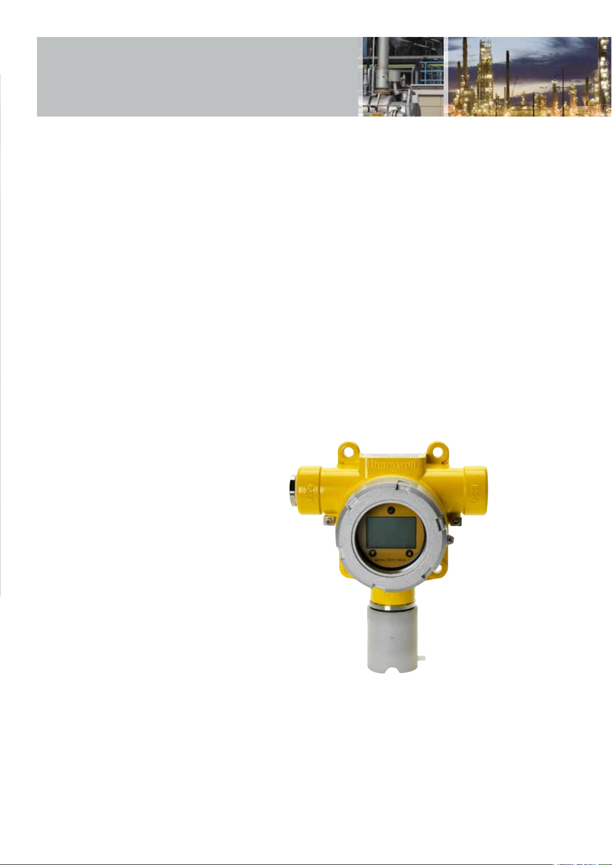
Series 3000 MkII and MkIII
2-wire loop powered toxic and
Oxygen gas detector for use in
potentially explosive atmospheres
- explosion proof and intrinsically
safe versions
Page 2
Series 3000 MkII
and MkIII
Reliable detection
• Proven electrochemical
sensing technology
• Uses Surecell™ electrochemical cells,
ideal for hot and humid environments
• Long-life sensing elements
• Patented ‘Reflex’ sensing element
verification diagnostics
Reduced installation costs
• Integral surface mounting lugs
• Optional horizontal or vertical pipe
mounting bracket
• Flameproof transmitter allows field
wiring to be run along with other
non-IS instruments
• Plug-in sensor removes wiring
• Can be retrofitted in place of Series 2000
Reduced commissioning costs
• Sensor recognition feature auto
configures transmitter
• Non-intrusive configuration
• Plug and play factory configured sensors
Reduced maintenance costs
• IS sensor connection permits hot swap,
reducing downtime
• User programmable calibration
frequency
• Integral fault diagnostic software
• Menu/icon driven calibration
procedure
Regulatory compliance
• European (ATEX)
• US (UL)
• Canadian (c-UL)
• South America (Inmetro)
• International (IECEx)
Range of optional accessories
• Remote sensor mounting kit
• Duct mounting kit (for H2, CO
and H2S only)
• Calibration cup to apply test gas
• Collecting cone
Typical applications
• Exploration and drilling platform
• Production platforms
• Onshore oil and gas terminals
• Refineries and chemical plants
• Power plants
• Waste water facilities
• Utilities
The Series 3000 range of transmitters provide
comprehensive monitoring of toxic and Oxygen gas
hazards in potentially explosive atmospheres. Suitable
for mounting both indoors and out, they are available in
two versions and offer excellent versatility. The MkII is
contained in a flameproof housing, has an intrinsically safe
sensor connection and is for use in predominantly Zone 1
applications. However with the use of the optional remote
mounting kit the sensor of the MkII can be mounted in a
Zone 0 environment. The MkIII is for use with a separate
suitable IS barrier allowing the complete transmitter to be
used in Zone 0 applications.
These low powered gas detectors all feature a loop
powered 4-20 mA connection, making them ideal for
both new and retrofit installations. Users can configure
the detector through the use of the easy to read LCD
and intuitive interface while fault diagnostic software
and a programmable calibration period greatly simplify
maintenance procedures.
The intrinsically safe smart sensors are
supplied pre-configured and can be ‘hot
swapped’ without having to remove power to
the detector, saving time and money during
commissioning and routine servicing. A remote
sensor mounting kit is available that allows the
sensor to be mounted up to 15m (50ft) from
the transmitter, making it ideal for operation in
areas that are difficult to access.
Series 3000 is supplied with all necessary
accessories for easy installation. The detector
can be wall mounted using the integral
mounting lugs or pipe mounted (horizontal or
vertical) using the optional pipe mounting kit.
Electrical installation is made using the
2 x M20 cable entries (ATEX/IECEx version) or
2 x ¾”NPT conduit entries (UL/c-UL versions).
A suitable blanking plug is also supplied to
seal any unused entries. A weatherproof cap
is included for use in the harshest outdoor
conditions.
Page 3
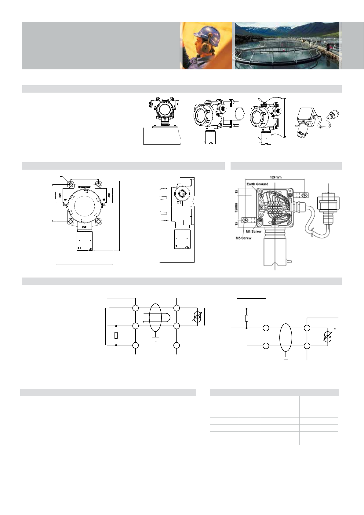
Installation
Controller Detector
V
Mechanical Installation Options
Series 3000 MkII and MkIII are designed for use
in potentially explosive atmospheres. As such,
installation should follow national guidelines
using suitable mechanically protected cable and
glands (M20 or ¾” NPT) or conduit (¾” NPT).
Use 0.5mm
cross sectional area cable as needed to ensure
minimum operating voltage at the detector,
depending on installed cable length. Various
accessories are available for different applications.
2
(20AWG) to 2.0mm2 (~14AWG)
Pipe Mounting Wall MountDuct Mount
Remote Mounting
Dimensions
Ø8.5
80
106
164
Wiring Schematics Series 3000 MkII
Detector supply V
• 17Vdc (min) to 32Vdc (max)
Maximum detector signal I
• 22mA (over range)
d
m
Cable resistance Rc
• Subject to cable type
Load resistor of control panel R
• Assumed 33Ω (min) or 250Ω (max)
• Subject to controller manufacturer
Controller supply voltage V
• Subject to controller manufacturer
• Assumed nominal of 24Vdc
c
Remote Mounting Arrangement
12
201
Note: All dimensions
99
Controller
R
+VE
c
L
Signal Signal
R
L
-VE
c
1
I
m
2
3
+VE
1
V
d
Signal
2
3
+VE
R
L
V
c
-VE -VE
R
c
1
I
m
2
in mm (1" = 25.4mm)
Detector
+VE
1
2
V
d
Typical Maximum Installed Cable Lengths Series 3000 MkII
The maximum cable length between a controller and detector is dependent upon:
• The minimum guaranteed supply voltage to the detector at
the controller (V
• The minimum operating voltage of the detector (V
).
C
• The maximum current draw of the detector (I
• The input impedance of the controller (R
• The resistance of the cable (R
Using the example values, the table opposite shows typical cable lengths.
For a specific application, the cable manufacturer’s resistance data for a specific cable type
must be used.
A cable length calculation formula can be found in the product technical manual.
Series 3000 MkII Maximum Cable Length shown in km (mi)
Cable Size Cable
2
0.5mm
)
d
)
m
)
L
)
C
(20AWG*) 36.8 (59.2) 3.9 (2.4) 0.9 (0.6)
2
(17AWG*) 19.5 (31.4) 7.3 (4.5) 1.7 (1.1)
1.0mm
2
(16AWG*) 12.7 (20.4) 11.2 (7.0) 2.7 (1.7)
1.5mm
2
(14AWG*) 10.1 (16.3) 14.1 (8.8) 3.4 (2.1)
2.0mm
*Nearest equivalent
Resistance
Ω/km
R
c
(Ω/mi)
Cable distance km
(mi) where the Input
Impedance
= 33Ω
R
L
Cable distance km (mi)
where the Input
Impedance
= 250Ω
R
L
Page 4

Installation
Wiring Schematics Series 3000 MkIII
Signal
Controller
+VE
R
L
1 1
-VE -VE
2 2
Simple Zener Barrier
or Isolator
B
A
R
R
I
E
R
Controller
Detector
+VE
+VE
R
L
Earth
3
1 1
Signal
2
-VE
3
4
Dual Zener Barrier
or ‘Mirror’ Isolator
Single Barrier Schematic Dual Barrier Schematic
Series 3000 MkIII Cable Length Suggested barriers and isolators Series 3000 MkIII
The limiting factors in calculating maximum cable lengths when using barriers
and isolators are the total capacitance and inductance. Barriers and isolators
have a fixed amount of capacitance and inductance that can be connected to
their outputs. The cable between the field device and barrier/isolator will have
a value for capacitance and inductance per metre or kilometre that will be
available from the manufacturer or supplier.
To calculate the maximum cable lengths, calculate the total capacitance
and inductance for the length of cable, add any capacitance or inductance
due to the field device (in the case of Series 3000 MkIII capacitance and
inductance = 0). The resulting totals should not be greater than the value
shown for the barrier or isolator.
Listed below are some suggested barriers and isolators for use with
Series 3000 MkIII.
MTL7728+ (single channel zener barrier)
MTL7787+ (2-channel zener barrier)
MTL5042 (Galvanic Isolator)
Pepperl+Fuchs KFD2-STC4-EX1 (Galvanic Isolator)
Note: It is up to the user to ensure that the barrier or isolator used is suitable for
their application.
2
3
Detector
+VE
Signal
Electrical Connections
Terminal Detector Controller
Number Terminal Connection
1 + +VE
2 - Signal
Page 5

Technical Summary
Series 3000 MkII and MkIII Detector
Use Rugged and reliable gas detector for the protection of personnel from toxic and Oxygen gas hazards. MkII version
suitable for use in Zone 1, 2, 21 or 22 hazardous areas and North American Class I and II Division 1 or 2 areas.
MkIII version suitable for use in Zone 0, 1, 2, 20, 21 or 22 applications.
Detectable Gases
Gas Formula Selectable Full
Scale Range
Oxygen
Hydrogen Sulphide
Hydrogen Sulphide
Carbon Monoxide
Sulphur Dioxide
Ammonia*
Ammonia*
Chlorine
Chlorine Dioxide
Nitric Oxide
Nitrogen Dioxide
Hydrogen
Hydrogen
Hydrogen Chloride
Hydrogen Cyanide
Hydrogen Fluoride
Phosphine
Fluorine
Ozone
Ethylene Oxide
O
H
H
CO
SO
NH
NH
CI
CIO
N0
NO
H
H
HCI
HCN
HF
PH
F
O
ETO
2
S
2
S
2
25.0% / Vol only 25.0%Vol -30°C / -22°F 55°C / 131°F
10.0 to 50.0ppm 15.0ppm -40°C / -40°F 55°C / 131°F
50 to 500ppm 100ppm -40°C / -40°F 55°C / 131°F
100 to 500ppm 300ppm -40°C / -40°F 55°C / 131°F
2
3
3
2
2
5.0 to 20.0ppm 15.0ppm -40°C / -40°F 55°C / 131°F
50 to 200ppm 200ppm -20°C / -4°F 40°C / 104°F
200 to 1,000ppm 1,000ppm -20°C / -4°F 40°C / 104°F
5.0 to 20ppm 5.0ppm -10°C / 14°F 55°C / 131°F
1.00ppm only 1.00ppm -20°C / -4°F 55°C / 131°F
100ppm only 100ppm -20°C / -4°F 55°C / 131°F
2
2
2
5.0 to 50.0ppm 10ppm -20°C / -4°F 55°C / 131°F
1,000ppm only 1,000ppm -20°C / -4°F 55°C / 131°F
9,999ppm only 9,999ppm -20°C / -4°F 55°C / 131°F
10.0 to 20.0ppm 10ppm -20°C / -4°F 40°C / 104°F
30.0ppm only 30.0ppm -20°C / -4°F 55°C / 131°F
12.0ppm only 12.0ppm -20°C / -4°F 55°C / 131°F
3
2
3
1.2ppm only 1.2ppm -20°C / -4°F 40°C / 104°F
4.00ppm only 4.00ppm -20°C / -4°F 55°C / 131°F
0.400ppm only 0.400ppm -20°C / -4°F 55°C / 131°F
20.0 to 50.0ppm 25.0ppm -20°C / -4°F 55°C / 131°F
Electrical
Connections and Power MkII MkIII
2-wire loop powered
17Vdc (±10%) to 32Vdc (max)
22mA max. over range
Recommended Cable
Signal
2-wire with screen (90% coverage) or conduit
2
0.5mm
(20AWG) to 2.0mm2 (14AWG)
0-100% FSD 4-20mA
Fault = 3mA
Calibration due selectable off or 3mA
Max. over range 22mA
Inhibit (toxic sensors) = Selectable 3mA or 4mA
Inhibit (Oxygen sensors) = Selectable 3mA or 17.4mA
Construction
Material Transmitter: Epoxy painted aluminium alloy LM25 or 316 Stainless Steel, Sensor: 316 Stainless Steel with PTFE filter
Maximum Dimensions 164mm x 201mm x 99mm (6.4” x 7.9” x 3.9”)
Weight Aluminium alloy LM25: 1.7kg (3.75lbs.) Stainless Steel 316: 3.7kg (8.16lbs.)
Environmental
IP Rating IP66 (EN 60529), NEMA 4X
Certified Temperature ATEX/IECEX: -20°C to +55°C (-4°F to +131°F) (MkIII -40°C to +55°C (-40°F to +131°F))
UL/c-UL: -40°C to +55°C (-40°F to +131°F)
Operating Humidity Continuous 20-90% RH (non-condensing) Intermittent 0-99% RH (non-condensing)
Operating Pressure 90-110kPa
Storage Conditions 15°C to 30°C (59°F to 86°F), 30-70% RH (non-condensing)
Default Range Operating Temperature**
Min Max
1
2 wire loop powered
10Vdc (±10%) to 30Vdc (max)
22mA max. overrange
Entity parameters for Barrier Selection:
Vmax/Ui = 30Vdc
Imax/Ii = 125mA
Pmax/Pi = 1.2W
Li = 0mH
Ci = 0µF
*Suitable for applications without NH3
ambient background concentrations only.
**When operating in Hazardous Area
applications the detector must not be
operated outside the certified temperature
range. See Certification details for UL,
c-UL and ATEX/IECEx certified temperature
ranges.
1
+55°C / 131°F intermittent.
Page 6

Technical Summary
and Ordering Information
Certification
MkII MkIII
Transmitter:
UL/c-UL: Class I, Div. 1 & 2, Groups B, C & D;
Class II, Div. 1 Groups E, F & G, Class II, Div. 2, Groups
F & G; Class I, Zone 1, Group IIB + H2 Hazardous
Locations
II 2 (1) GD Ex d [ia IIC Ga] IIB + H2 T4 Gb
ATEX:
Ex t [ia IIIC Da] IIIB T135°C Db
IECEx: Ex d [ia IIC Ga] IIB + H2 T4 Gb Ex t [ia IIIC Da]
IIIB T135°C Db
Transmitter:
UL/cUL Class I, Divisions 1 & 2, Groups A, B, C & D;
Class II, Divisions 1 & 2, Groups E, F & G
II 1 (1) GD Ex ia IIC T4 Ga Ex ia IIIC T135°C Da
ATEX:
IECEx: Ex ia IIC T4 Ga Ex ia IIIC T135°C Da
Remote Sensor Accessory:
UL/c-UL: Class I, Division 1, Groups A, B, C and D
Class II, Divisions 1 and 2, Groups E, F and G
Class 1, Zone 0, Group IIC; Class II, Zone 20
II 1G D Ex ia IIC T4 Ga Ex ia IIIC T135°C Da
ATEX:
IECEx: Ex ia IIC T4 Ga Ex ia IIIC T135°C Da
Approvals CE compliant in accordance with: ATEX Directive 94/9/EC, EMC Directive 2004/108/EC, EN 50270
Ordering Information
Remote Sensor Accessory:
UL/c-UL = Class I, Div. 1, Groups A, B, C & D; Class II
Division 1 & 2, Groups E, F & G; Class 1, Zone 0, Group IIC;
Class II, Zone 20
II 1G D Ex ia IIC T4 Ga Ex ia IIIC T135°C Da
ATEX:
IECEx: Ex ia IIC T4 Ga Ex ia IIIC T135°C Da
A complete assembly consists of two parts, a transmitter and sensor which must be ordered separately.
• Transmitter PN#: Two certified versions are available:
- ATEX/IECEx approved version (Aluminium version part number S3KAL2, S3KAL3 Stainless Steel version part
number S3KAS2, S3KAS3)
- UL/CSA approved version (Aluminium version part number S3KUL2, S3KUL3, Stainless Steel version part
number S3KUS2, S3KUS3)
- Inmetro approved version (Aluminium version part number S3KNL2, S3KNL3, Stainless Steel version part
number S3KNS2, S3KNS3)
• Sensor PN#: All certified ATEX, IECEx, UL, CSA (c-UL) with two digits to specify gas type and range:
- e.g. S3KXXC1SS (C1 denotes Carbon Monoxide, with a default range of 0-300ppm and user configurable for
ranges from 0-100ppm to 0-500ppm (in 100ppm steps))
Transmitter
L - LM25 Aluminium
S - 316 Stainless Steel
Series 3000 Transmitter
S3KAL3
A - ATEX/IECEx approved
U - UL/c-UL approved
N - Inmetro approved
Sensor Part Numbers and Available Gases
S3KXSO1SS Oxygen (O
S3KXSC1SS Carbon Monoxide (CO) 0-300ppm (default) 0-100 to 0-500ppm selectable
S3KXSC2SS Carbon Monoxide (CO) 0-300ppm (default) 0-100 to 0-999ppm selectable
S3KXSH1SS Hydrogen Sulphide (H
S3KXSH2SS Hydrogen Sulphide (H
S3KXSL1SS Chlorine (CI
S3KXSS1SS Sulphur Dioxide (SO
S3KXSX1SS Chlorine Dioxide (CIO
) 0-25% Vol
2
S) 0-15ppm (default) 0-10 to 0-50ppm selectable
2
S) 0-100ppm (default) 0-50 to 0-500ppm selectable
2
) 0-5ppm (default) 0-5 to 0-20ppm selectable
2
) 0-15ppm (default) 0-5 to 0-20ppm selectable
2
) 0-1ppm only
2
2 - MkII version
3 - MkIII version
Page 7

Ordering Information Continued
Ordering Information Continued
S3KXSM1SS Nitrogen Monoxide (NO) 0-100ppm only
S3KXSN1SS Nitrogen Dioxide (NO
S3KXSG1SS Hydrogen (H
S3KXSG2SS Hydrogen (H2) 0-10,000 only
S3KXSR1SS Hydrogen Chloride (HCI) 0-10ppm (default) 0-10 to 0-20ppm selectable
S3KXSA1SS Ammonia (NH
S3KXSA2SS Ammonia (NH
S3KXSY1SS Hydrogen Cyanide (HCN) 0-30 ppm only
S3KXSF1SS Hydrogen Fluoride 0-12 ppm only
S3KXSP1SS Phosphine 0-1.2 ppm only
S3KXSU1SS Florine (F
S3KXSZ1SS Ozone (O
2
3
S3KXSE1SS Ethylene Oxide (ETO) 0-25.0ppm (default) 0-20.0 to 0-50.0ppm selectable
Shipping Details
Shipping carton dimensions 315mm (12.4”) (L) x 230mm (9.0”) (W) x 115mm (4.5”) (D)
Approximate weight Aluminium alloy LM25 : 1.7kg (3.75lbs.) Stainless Steel 316 : 3.7kg (8.16lbs.)
Optional Accessories
SPXCDMTBR Pipe Mounting Bracket
SPXCDSDP Sunshade/Deluge Protection
S3KCAL Calibration gas flow housing
S3KCC Collecting cone (for use when detecting Hydrogen gas only)
S3KDMK Duct mounting kit (for use when detecting O
S3KRMK ATEX/UL/c-UL approved remote sensor mounting kit (includes enclosure with sensor socket, 15m (50 feet)
of digital cable and glands, transmitter cable plug, mounting screws)
Calibration Gases Contact Honeywell Analytics representative
) 0-10 ppm (default) 0-5 to 0-50 ppm selectable
2
) 0-1000ppm only
2
) 0-200ppm (default) 0-50 to 0-200ppm selectable
3
) 0-1000ppm (default) 0-200 to 0-1,000ppm selectable
3
) 0-4.00ppm only
) 0-0.400ppm only
, CO, H2S or H2 gas)
2
Page 8

Honeywell Analytics Gas Detection
Honeywell Analytics is able to provide gas detection solutions to meet the requirements of all
applications and industries. Contact us in the following ways:
Headquarters
Europe, Middle East, Africa
Life Safety Distribution AG
Javastrasse 2
8604 Hegnau
Switzerland
Tel: +41 (0)44 943 4300
Fax: +41 (0)44 943 4398
gasdetection@honeywell.com
Customer Service:
Tel: 00800 333 222 44
Tel: +41 44 943 4380 (Alternative number)
Fax: 00800 333 222 55
Middle East Tel: +971 4 450 5800 (Fixed Gas Detection)
Middle East Tel: +971 4 450 5852 (Portable Gas Detection)
(Freephone number)
Technical Support Centres
Honeywell Analytics Ltd.
4 Stinsford Road
Nufeld Industrial Estate
Poole, Dorset, BH17 0RZ
United Kingdom
Tel: +44 (0) 1202 645 544
Fax: +44 (0) 1202 645 555
Honeywell Analytics
ZAC Athélia 4 - 375 avenue du Mistral
Bât B, Espace Mistral
13600 La Ciotat
France
Tel: +33 (0) 4 42 98 17 75
Fax : +33 (0) 4 42 71 97 05
Americas
Honeywell Analytics Distribution Inc.
405 Barclay Blvd.
Lincolnshire, IL 60069
USA
Tel: +1 847 955 8200
Toll free: +1 800 538 0363
Fax: +1 847 955 8210
detectgas@honeywell.com
Honeywell Analytics
Elsenheimerstrasse 43
80687 München
Germany
Tel: +49 89 791 92 20
Fax: +49 89 791 92 43
Asia Pacic
Honeywell Analytics
Asia Pacic
#701 Kolon Science Valley (1)
43 Digital-Ro 34-Gil, Guro-Gu
Seoul 152-729
Korea
Tel: +82 (0) 2 6909 0300
Fax: +82 (0) 2 2025 0388
India Tel: +91 124 4752700
analytics.ap@honeywell.com
Honeywell Analytics
P.O. Box-45595
6th Street
Musaffah Industrial Area
Abu Dhabi
UAE
Tel: +971 2 554 6672
Fax: +971 2 554 6672
EMEA: HAexpert@honeywell.com
US: ha.us.service@honeywell.com
AP: ha.ap.service@honeywell.com
www.honeywellanalytics.com
www.raesystems.com
Honeywell Analytics
Experts in Gas Detection
Please Note:
While every effort has been made to ensure accuracy in this publication, no responsibility can be accepted for errors or
omissions. Data may change, as well as legislation, and you are strongly advised to obtain copies of the most recently
issued regulations, standards, and guidelines. This publication is not intended to form the basis of a contract.
12113_H_Series 3000 MkII & MkIII_DS01057_V9_EMEA
05/15
© 2015 Honeywell Analytics
 Loading...