

Page 1

Honeywell Process Solutions
Profibus-DP(Pnet) Module
2MLL-PMEB/PSRA/PSEA
User's Guide
R240
January 2018
Release 240
Honeywell
Page 2

Notices and Trademarks
Copyright 2019 by Honeywell International
Sárl. Release 240 January 2019
While this information is presented in good faith and believed to be accurate, Honeywell disclaims
the implied warranties of merchantability and fitness for a particular purpose and makes no
express warranties except as may be stated in its written agreement with and for its customers.
In no event is Honeywell liable to anyone for any indirect, special or consequential damages. The
information and specifications in this document are subject to change without notice.
Honeywell, PlantScape, Experion PKS, and TotalPlant are registered trademarks of Honeywell
International Inc.
Other brand or product names are trademarks of their respective owners.
Honeywell Process Solutions
1860 W. Rose Garden Lane
Phoenix, AZ 85027 USA
1-800 822-7673
ii Fast Ethernet Module 2MLL-EFMTB/EFMFB User's Guide R240
Honeywell
January 2018
Page 3

Revision History
Version Date Remark Page
V 1.0 ’06.02 First Edition -
V1.1 ’07.10 2MLI-CPUU added -
V 2.0 ’10.08 2MLR CPU added -
Ch. 11 Compliance with EMC Specification added -
2MLL-PMEC added -
PROFICON configuration tool added -
Automatic Network Scan modified Ch.9.1.1
2MLL-PSRA added Ch.1.3.3
V 2.1 ’11.05 How to enable link through flag added Ch.5.2.3
V 2.2 ’11.06
V2.3 ’14.11 SoftMaster V4.0 UI Updated -
V2.4 ’16.03
Performance specifications added
- Max. number of modules per node : 24 Modules
Add 2MLL-PMEB
- PROFIBUS DPv1 setting
- P2P communication setting
- SoftMaster UI updated (2MLL-PMEB contents, P2P
settings)
Ch.2.2
-
Page 4

About User’s Manual
Thanks for purchasing ML PLC of Honeywell
Before use, make sure to carefully read and understand the User’s Manual about the functions, performances, installation and
programming of the product you purchased in order for correct use and importantly, let the end user and maintenance
administrator to be provided with the User’s Manual.
The User’s Manual describes the product. If necessary, you may refer to the following description and order accordingly. In
addition, you may connect our website (www.honeywellprocess,com/) and download the information as a PDF file.
Relevant User’s Manuals
Tit le Desc rip tio n
SOFTMASTER software user manual describing online function
SOFTMASTER User’s Manual
SOFTMASTER User’s Manual
(for 2MLI, 2MLR)
2MLK/MLM/MLC Instructions &
Programming User’s Manual
2MLI/2MLR/MLI Instructions &
Programming User’s Manual
2MLK CPU User’s Manual
(2MLK-CPUA/CPUE/CPUH/CPUS/CPUU)
2MLI CPU User’s Manual
(2MLI-CPUU)
such as programming, print, monitoring, debugging by using
2MLK, ML50 CPU
SOFTMASTER software user manual describing online function
such as programming, print, monitoring, debugging by using
2MLI, 2MLR CPU
User’s manual for programming to explain how to use
instructions that are used PLC system with 2MLK, MLM/MLC
CPU.
User’s manual for programming to explain how to use
instructions that are used PLC system with 2MLI, 2MLR, MLI
CPU.
2MLK-CPUA/CPUE/CPUH/CPUS/CPUU user manual
describing about 2MLK CPU module, power module, base, IO
module, specification o f e xtension cable and system
configuration, EMC standard
2MLI-CPUU user manual describing about 2MLI CPU module,
power module, base, IO module, specification of extension cable
and system configuration, EMC standard
2MLR redundant series User’s
Manual
N Configurator User’s Manual
Current user manual is written based on the following version.
Related OS version list
Model O/S vers ion
2MLK-CPUH, CPUS, CPUA, CPUE V2.0
2MLI-CPUU, CPUH V2.0
SOFTMASTER V4.2
2MLR-CPUH/F, CPUH/T V1.0
1 Pnet I/F Module 2MLL-PSRA, 2MLL-PMEB User’s Guide
Honeywell
2MLR-CPUU user manual describing about 2MLR CPU module,
power module, extension drive, base, IO module, specification of
extension cable and system configuration, EMC standard
User’s manual for Pnet, Dnet configuration tool, N Configurator
R240
January2019
Page 5

◎ Contents ◎
Chapter 1 Introduction
Chapter 2 Specifications
Chapter 3 Installation and Test Operation
1.1 Introduction -------------------------------------------------------------------------------------------------------- 1-1
1.2 Characteristics ---------------------------------------------------------------------------------------------------- 1-1
1.3 Product Configuration ---------------------------------------------------------------- --------------------------- 1-2
1.3.1 Model Name ------------------------------------------------------------------------------------------------ 1-2
1.3.2 Available number by CPU ------------------------------------------------------------------------------- 1-2
1.3.3 Slave Device ----------------------------------------------------------------------------------------------- 1-3
1.4 Software ------------------------------------------------------------------------------------------------------------- 1-4
1.4.1 Check list for the software ------------------------------------------------------------------------------ 1-4
1.4.2 SOFTMASTER -------------------------------------------------------------------------------------------- 1-5
1.4.3 Checking the version ------------------------------------------------------------------------------------- 1-5
2.1 General Specifications ------------------------------------------------------------------------------------------ 2-1
2.2 Performance Specifications ----------------------------------------------------------------------------------- 2-2
2.3 Structure & Characteristics ------------------------------------------------------------------------------------ 2-3
2.3.1 Structure of Pnet I/F module -------------------------------------------------------------------------- 2-3
2.4 Cable Specifications --------------------------------------------------------------------------------------------- 2-6
2.4.1 Cable specifications of Belden network ------------------------------------------------------------- 2-6
3.1 Precautions for Installation ------------------------------------------------------------------------------------ 3-1
3.1.1 Precautions for Installation --------------------------------------------------------------------------- 3-1
3.2 From Setting to Operation ------------------------------------------------------------------------------------- 3-2
3.3 Installation of the product -------------------------------------------------------------------------------------- 3-3
3.3.1 Installation of 2MLL-PMEA --------------------------------------------------------------------------- 3-3
3.4 Test Operation ---------------------------------------------------------------------------------------------------- 3-6
3.4.1 Precautions for system configuration ------------------------------------------------------------- 3-6
1 Pnet I/F Module 2MLL-PSRA, 2MLL-PMEA, 2MLL-PMEB User’s Guide R240
Honeywell January 2019
Page 6

Chapter 4 System Configuration
Chapter 5 Communication Program
Chapter 6 SyCon Setting
4.1 System Configuration of Network ---------------------------------------------------------------------------- 4-1
4.1.1 ML200 Pnet + Smart I/O ----------------------------------------------------------------------------- 4-1
4.1.2 ML200 Pnet + Composite System ----------------------------------------------------------------- 4-2
5.1 Communication Program --------------------------------------------------------------------------------------- 5-1
5.1.1 Type of communication program ------------------------------------------------------------------- 5-1
5.2 SOFTMASTER --------------------------------------------------------------------------------------------------- 5-2
5.2.1 Setting PLC type ----------------------------------------------------------------------------------------- 5-2
5.2.2 Registration of the communication module ------------------------------------------------------- 5-4
5.2.3 Uploading High Speed Link parameter and setup ----------------------------------------------- 5-8
5.2.4 Setting P2P Parameter ---------------------------------------------------------------- ---------------- 5-1 1
6.1 Introduction -------------------------------------------------------------------------------------------------------- 6-1
6.1.1 Main functions ------------------------------------------------------------------------------------------ 6-1
6.1.2 Characteristics ------------------------------------------------------------------------------------------ 6-1
6.2 Installation --------------------------------------------------------------------------------------------------------- 6-1
6.2.1 System requirements --------------------------------------------------------------------------------- 6-1
6.2.2 Software installation ----------------------------------------------------------------------------------- 6-2
6.3 Communication settings in SyCon -------------------------------- ------------------------------------------- 6-8
6.3.1 Initial screen --------------------------------------------------------------------------------------------- 6-8
6.3.2 Composition of menu --------------------------------------------------------------------------------- 6-9
6.3.3 New file ------------------------------------------------------------------------------------------------ -- 6-1 1
6.3.4 Master selection --------------------------------------------------------------------------------------- 6-12
6.3.5 Slave selection ----------------------------------------------------------------------------------------- 6-15
6.3.6 Bus parameter ----------------------------------------------------------------------------------------- 6-17
6.4 On-line Function ------------------------------------------------------------------------------------------------- 6-18
6.4.1 Introduction --------------------------------------------------------------------------------------------- 6-18
6.4.2 Online to the CIF -------------------------------------------------------------------------------------- 6-18
6.4.3 Automatic network scan ----------------------------------------------------------------------------- 6-18
6.4.4 Start/Stop communication --------------------------------------------------------------------------- 6-20
6.4.5 Debug mode -------------------------------------------------------------------------------------------- 6-20
6.4.6 Diagnostic functions ---------------------------------------------------------------------------------- 6-20
2 Pnet I/F Module 2MLL-PSRA, 2MLL-PMEA, 2MLL-PMEB User’s Guide R240
Honeywell January 2019
Page 7

Chapter 7 N Configurator Setting
Chapter 8 High-speed Link
7.1 Introduction -------------------------------------------------------------------------------------------------------- 7-1
7.1.1 Main functions ------------------------------------------------------------------------------------------ 7-1
7.1.2 Characteristics ------------------------------------------------------------------------------------------ 7-1
7.2 Installation --------------------------------------------------------------------------------------------------------- 7-2
7.2.1 System requirements --------------------------------------------------------------------------------- 7-2
7.2.2 How to install Program --------------------------------------------------------------------------------- 7-2
7.3 Start PROFICON -------------------------------------------------------------------------------------------------- 7-3
7.3.1 Screen composition ------------------------------------------------------------------------------------- 7-3
7.3.2 Menu composition --------------------------------------------------------------------------------------- 7-4
7.3.3 New Project(New File) -------------------------------------------------------------------------------- 7-10
7.4 Network composition through PROFICON ----------------------------------------------------------------- 7-11
7.4.1 Master composition ------------------------------------------------------------------------------------ 7-11
7.4.2 Slave composition -------------------------------------------------------------------------------------- 7-13
7.4.3 Bus parameter ------------------------------------------------------------------------------------------- 7-16
7.5 Download and upload Network Configuration ------------------------------------------------------------- 7-17
7.5.1 Download Network Settings ------------------------------------------------------------------------- 7-17
7.5.2 Upload Network Settings ----------------------------------------------------------------------------- 7-19
7.6 Diagnosis function -------------------------------- ---------------------------------------------------------------- 7-20
7.6.1 Start / Stop Communication -------------------------------------------------------------------------- 7-20
7.6.2 Debug mode (Start/Stop Debug Mode, Device Diagnostics) -------------------------------- 7-20
7.6.3 Live List --------------------------------------------------------------------------------------------------- 7-22
7.6.4 Automatic Network Scan ------------------------------------------------------------------------------ 7-23
7.6.5 I/O Data Monitoring ------------------------------------------------------------------------------------ 7-24
7.6.6 Disconnection Report ---------------------------------------------------------------------------------- 7-25
7.6.7 Master information (Device Information) ---------------------------------------------------------- 7-25
7.6.8 Master reset (Firmware Reset) ---------------------------------------------------------------------- 7-25
8.1 Introduction -------------------------------------------------------------------------------------------------------- 8-1
8.2 Process of High-speed Link Send/Receive Data --------------------------------------------------------- 8-2
8.3 Operation Sequence of High-speed Link ------------------------------------------------------------------- 8-3
8.4 High Speed Link Parameter Setting--------------------------------------------------------------------------- 8-4
8.5 High-speed Link Information --------------------------------------------------------------------------------- 8-10
8.5.1 Monitor of High-speed link information ---------------------------------------------------------- 8-12
3 Pnet I/F Module 2MLL-PSRA, 2MLL-PMEA, 2MLL-PMEB User’s Guide R240
Honeywell January 2019
Page 8

Chapter 9 P2P
Chapter 10 Program Example
Chapter 11 Troubleshooting
Chapter 12 Compliance with EMC Specifications
9.1 Introduction -------------------------------------------------------------------------------------------------------- 9-1
9.2 Process of P2P Read/Write Data ---------------------------------------------------------------------------- 9-2
9.3 Operation Sequence of P2P ---------------------------------------------------------------------------------- 9-3
9.4 P2P Parameter Setting ------------------------------------------------------------------------------------------- 9-4
9.5 P2P Informatio-n ------------------------------------------------------------------------------------------------- 9-9
10.1 Example of Communication with PMEA ----------------------------------------------------------------- 10-1
10.1.1 SyCon settings --------------------------------------------------------------------------------------- 10-1
10.1.2 SOFTMASTER settings ---------------------------------------------------------------------------- 10-9
10.2 Example of Communication with PMEA --------------------------------------------------------------- 10-14
10.2.1 PROFICON settings ------------------------------------------------------------------------------ 10-14
10.2.2 SOFTMASTER settings -------------------------------------------------------------------------- 10-23
11.1 Symptoms and Management by LED Status ----------------------------------------------------------- 11-1
11.2 System Diagnosis of SOFTMASTER -------------------------------- ------------------------------------- 11-2
11.2.1 Information on communication module --------------------------------------------------------- 11-2
11.2.2 High-speed link --------------------------------------------------------------------------------------- 11-3
11.2.3 Log ------------------------------------------------------------------------------------------------------ 11-3
11.2.4 Auto-scan ---------------------------------------------------------------------------------------------- 11-4
11.3 Diagnosis of Communication Module through SOFTMASTER ------------------------------------- 11-5
11.4 Troubleshooting ------------------------------------------------------------------------------------------------ 11-6
11.4.1 SyCon abnormal connection ---------------------------------------------------------------------- 11-6
11.4.2 SOFTMASTER abnormal connection ---------------------------------------------------------- 11-7
11.4.3 Abnormal connection with slave module ------------------------------------------------------- 11-8
12.1 Requirements Complying with EMC Specifications ---------------------------------------------------- 12-1
12.1.1 EMC specifications ----------------------------------------------------------------------------------- 12-1
12.1.2 Panel ----------------------------------------------------------------------------------------------------- 12-2
12.1.3 Cable ----------------------------------------------------------------------------------------------------- 12-3
12.2 Requirements Complying with Low Voltage Direction ------------------------------------------------ 12-4
12.2.1 Specifications applicable to ML200 series ------------------------------------------------------ 12-4
12.2.2 Selection of ML200 series PLC -------------------------------------------------------------------- 12-4
4 Pnet I/F Module 2MLL-PSRA, 2MLL-PMEA, 2MLL-PMEB User’s Guide R240
Honeywell January 2019
Page 9

Appendix
A.1 Terminology ------------------------------------------------------------------------------------------------------- A-1
A.2 List of Flags ------------------------------------------------------------------------------------------------------- A-3
A.2.1 High-speed link flags ------------------------------------------------------------------------------------ A-3
A.2.2 Link devices (N) ------------------------------------------------------------------------------------------ A-6
A.3 Dimensions -------------------------------------------------------------------------------------------------------- A-8
5 Pnet I/F Module 2MLL-PSRA, 2MLL-PMEA, 2MLL-PMEB User’s Guide R240
Honeywell January 2019
Page 10
Chapter 1 Introduction
1.1 Introduction
1.2 Characteristics
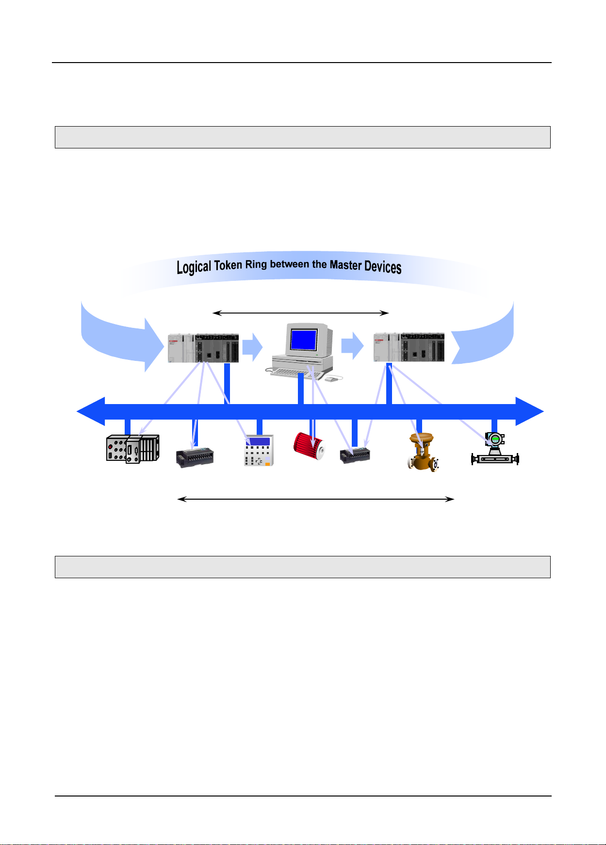
Active Stations, Master Devices
PC
Passive Stations (Slave Devices) are polled
PROFIBUS
Chapter 1 Introduction
This user’s manual is to describe Profibus-DP (Decentralized Peripherals) Master I/F module (hereinafter
referred to as Pnet I/F module) among communication modules of ML200 PLC system.
Profibus-DP is specified in IEC Fieldbus Standard IEC 1158.
In this communication, Token Ring is used to control the communication and to configure the network easily.
Pnet I/F module is a module to control the field bus with Twisted Shielded Pair Copper Cable applied.
ML200 Pnet I/F module has the characteristics as follows;
▶ Conforms to the international standard of EN 50170
▶ Supports Auto Baud Rate Detect
▶ Supports Sync/Freeze mode
▶ Max. input data : 244 Bytes/Slave
▶ Max. output data: 244 Bytes/Slave
▶ Max. data size : 244 Bytes/Slave, 10 kbyte/Master
▶ Communication speed : 9.6k, 19.2k, 31.25k, 45.45k, 93.7k, 187.5k, 500k, 1.5M, 3M, 6M, 12M
1 Pnet I/F Module 2MLL-PSRA, 2MLL-PMEA, 2MLL-PMEB User’s Guide R240
Honeywell January 2019
Page 11
Chapter 1 Introduction
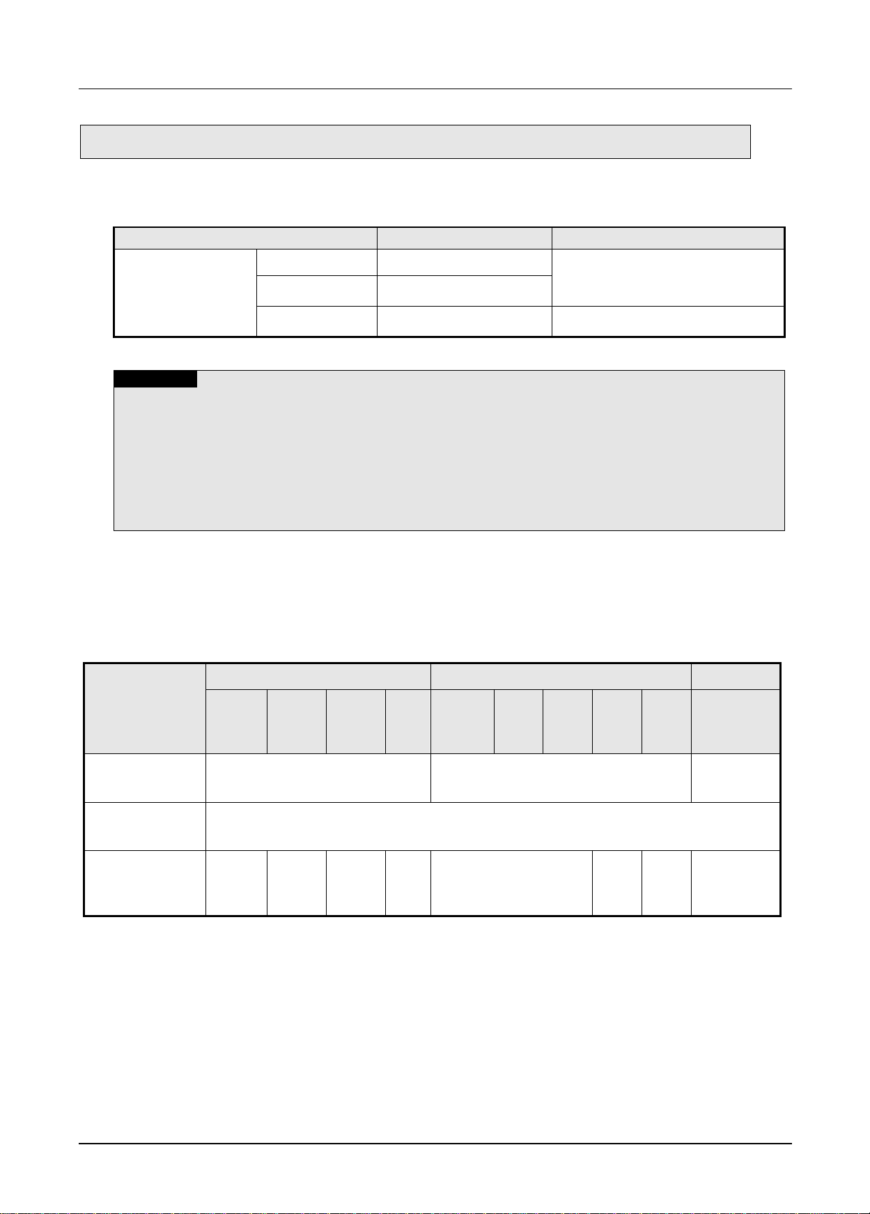
1.3 Product Configuration
Model
Contents
Remark
2MLK/2MLI/2MLR
2MLL-PMEA
Profibus-DP Master
Supports DP-V0
2MLL-PMEC
Profibus-DP Master
2MLL-PMEB
Profibus-DP Master
Supports DP-V1
Note
(1) ML200 Pnet supports only Profibus-DP. FMS, PA are not supported and protocol conversion is
available by the coupler
(2) Support of the DP version
1) DP-V0: Periodical data exchange between the PLC and the slave device
(Node diagnosis, module status, specific channel diagnosis)
2) DP-V1: Asynchronous data exchange between the PC or PLC and the slave device, integration of
EDD and FDT, fail-safe communication, alarm
3) DP-V2: supports broadcast, clock synchronization and time stamp, HART, upload/download,
redundancy
Item
2MLK
2MLI
2MLR
2MLKCPUH
/CPUU
2MLK-
CPUA
/CPUS
2MLK-
CPUE
2MLI-
CPUU
2MLI-
CPUH
2MLI-
CPUS
2MLI-
CPUE
2MLR-
CPUH/T
2MLR-
CPUH/F
The number of the
module using High
Speed Link (Max.)
12
12
12
The number of the
module using P2P
(Max.)
2MLL-PMEA/C: Not supported
2MLL-PMEB: 8
The number of
available
expansion base
(Max.)
7 3
1 7 3 1 31
1.3.1 Model Name
This describes on the product configuration of the ML200 Pnet I/F module.
1.3.2 Available number by CPU
You can mount up to 12 Pnet I/F module. If possible, mount the module in the basic base for best
performance of the communication module. The following table indicates the available service type by the
CPU. When configuring the system, apply this considering the number of the communication module.
2 Pnet I/F Module 2MLL-PSRA, 2MLL-PMEA, 2MLL-PMEB User’s Guide R240
Honeywell January 2019
Page 12

Chapter 1 Introduction
Item
Connection
cable
Model
Product code
contents
Remark
Master
module
Twisted pair
(Electricity)
2MLL-PMEA
47200001
Profibus DPv0
Sycon
2MLL-PMEC
47200103
Profibus DPv0
ProfiCon
2MLL-PMEB
47200180
Profibus DPv1
Item
Connection cable
Model
Product code
contents
Remark
Slave
module
Twisted pair
(electricity)
MPL-D22A
47060007
DC input 16 points
Fixed type, 9-pin
communication
connector
MPL-D24A
47060009
DC input 32 points
MPL-TR2A
47060008
TR output 16 (0.1A, Sink)
MPL-TR4A
47060010
TR output 32 (0.1A, Sink)
MPL-RY2A
47060011
Relay output 16
MPL-DT4A
47060012
DC input 16/ TR output 16
MPL-D22C
47060046
DC input 16
Removable type, 9-pin
communication
connector
MPL-D24C
47060047
DC input 32
MPL-TR2C
47060048
TR output 16 (0.5A, Source)
MPL-TR4C
47060049
TR output 32 (0.5A, Source)
MPL-RY2C
47060051
Relay output 16
MPL-DT4C
47060050
DC input16/ TR output 16
MPL-TR2B
47060059
TR output 16 (0.5A, Source)
Fixed type, 9-pin
communication
connector
MPL-TR4B
47060058
TR output 32 (0.5A, Source)
MPL-DT4B
47060060
DC input16/ TR output 16
MPL-TR2A1
47060084
TR output 16 (0.5A, Sink)
MPL-TR4A1
47060076
TR output 32(0.5A, Sink)
MPL-DT4A1
47060078
DC input 16/ TR output 16
MPL-TR2C1
47060085
TR output 16 (0.5A, Sink)
Removable type, 9-pin
communication
connector
MPL-TR4C1
47060077
TR output 32 (0.5A, Sink)
MPL-DT4C1
47060079
DC input 16/ TR output 16
MPL-AV8C
47060123
Analog voltage input, 8 channels
MPL-AC8C
47060124
Analog current input 8 channels
MPL-DV4C
47060125
Analog voltage output, 8
MPL-DC4C
47060126
Analog current output, 8
MPL-BSSA
47060130
Expansion type Pnet I/F module
Module for expansion
type Pnet I/F module
2MLL-PSRA
47200128
Pnet Remote I/F module
Remote I/F module
Note
1) Fixed type: The product whose I/O terminal block is fixed at the module
2) Removable type: The product whose I/O terminal block can be removed
1.3.3 Slave Device
The Pnet I/F module can be connected with Smart I/O series and available product list is as follows.
(1) Master module
(2) Slave module
[Table1.3.1] Pnet I/F module product list (Smart I/O)
3 Pnet I/F Module 2MLL-PSRA, 2MLL-PMEA, 2MLL-PMEB User’s Guide R240
Honeywell January 2019
Page 13
Chapter 1 Introduction
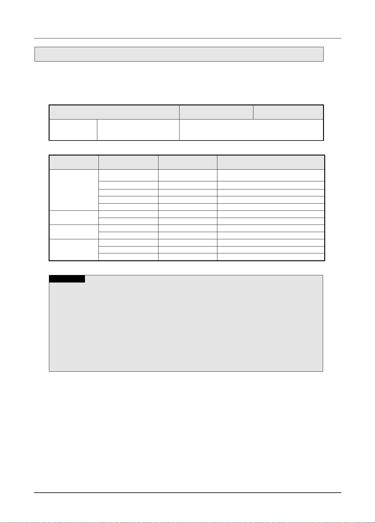
1.4 Software
Item
Programming tool
Communication
configuration tool
2MLL-PMEA
2MLL-PMEC
2MLL-PMEB
Profibus-DP master module
SOFTMASTER
Item
Model
Available version
(recommended)
Remark
2MLK series
2MLK-CPUH
V2.0
2MLK-CPUS
V2.0
2MLK-CPUA
V2.0
2MLK-CPUE
V2.0
2MLK-CPUU
V1.0
2MLI series
2MLI-CPUH
V1.0
2MLI-CPUU
V1.0
2MLR series
2MLR-CPUH/T
V1.0
2MLR-XPUH/F
V1.0
Software
SOFTMASTER
V4.2
SyCon
V2.0
Configuration tool for 2MLL-PMEA
N Configurator
V3.1.x or later
Configuration tool for 2MLL-PMEB/C
Note
(1) You can download the above software from our web site. In case Internet is available, visit the
nearest distributor and get the installation CD.
Web site address: http://www.lsis.com/
(2) You can program the SOFTMASTER through the RS-232C port and USB of the CPU module. For
the cable, refer to wiring diagram of the CPU module.
(3) You can configure the network system by SyCon through the “Config” port of the 2MLL-PMEA.
Only 9-pin serial port is available and simultaneous connection with SOFTMASTER is not
available.
(4) You can set the parameter by N Configurator for 2MLL-PMEB/C through the USB port of the CPU
module and connection with SOFTMASTER is available.
(5) In case you use the product other than available version, some function may not work properly. If
possible, use the recommended version and check the compatibility.
This describes on the software tool for the Pnet I/F module. For programming and application, refer to the
followings
1.4.1 Check list for the software
(1) Software list
(2) Selecting the CPU (Version) to use the Pnet I/F module
4 Pnet I/F Module 2MLL-PSRA, 2MLL-PMEA, 2MLL-PMEB User’s Guide R240
Honeywell January 2019
Page 14

Chapter 1 Introduction
1.4.2 SOFTMASTER
SOFTMASTER is software tool dedicated for the communication module including Pnet I/F module.
Setting the basic parameter, writing the frame and network diagnosis are available for the
communication module. Fore more detail, refer to Ch5. SOFTMASTER.
The following figure is an initial screen of the SOFTMASTER
[Figure 1.4.1] SOFTMASTER initial screen
1.4.3 Checking the version
Before using the Pnet I/F module, check the version of the module
(1) Check through the SOFTMASTER
This is method reading the communication module information through online connection
If it is under normal interface with the CPU, you can get the information as follows.
a) Execute the SOFTMASTER
b) Connect to the CPU through “Connect” on the “Online” menu.
c) After connection, execute [Online]-[Communication module setting]-[System Diagnosis]
d) In the “System Diagnosis” screen, select “Module Information” by double-clicking the
communication module and pop-up window
e) Software information appears at the right-bottom.
5 Pnet I/F Module 2MLL-PSRA, 2MLL-PMEA, 2MLL-PMEB User’s Guide R240
Honeywell January 2019
Page 15

Chapter 1 Introduction
[Figure 1.4.2] Checking the version of the module through the SOFTMASTER
(2) Check through the case label of the product
The module information is attached at the external case every communication modules
In case online connection is not available, take a module apart and check the label in the module case.
6 Pnet I/F Module 2MLL-PSRA, 2MLL-PMEA, 2MLL-PMEB User’s Guide R240
Honeywell January 2019
Page 16
Chapter 2 Specifications
2.1 General Specifications
No.
Items
Specification
Reference
1
Ambient Temp.
0 ~ 55 C
2
Storag e T em p.
25 ~ 70 C
3
Ambient humidity
5 ~ 95%RH (Non-condensing)
4
Storage humidity
5 ~ 95%RH (Non-condensing)
5
Vibration Immunity
Occasional vibration
-
Frequency
Acceleration
Pulse width
Times
IEC61131-2
5≤f< 8.4 ㎐
-
3.5mm
10 times
each
direction (X,Y
and Z)
8.4≤f≤150 ㎐
9.8 ㎨(1G)
-
Continuous vibration
Frequency
Acceleration
Pulse width
5≤f< 8.4 ㎐
-
1.75mm
8.4≤f≤150 ㎐
4.9 ㎨(0.5G)
-
6
Shocks Immunity
P eak acceleration : 147 m/s2(15G)
D uration : 11ms
P ulse wave type : Half-sine (3 times each direction per each axis)
IEC61131-2
7
Noise Immunity
Square wave
impulse noise
AC : ±1,500V
DC : ±900V
LSIS internal
test spec.
Electrostatic
discharge
Voltage: 4kV (Contact discharge)
IEC61131-2
IEC61000-4-2
Radiated
electromagnetic
field noise
8 0 ~ 1 0 00 MHz, 10V/m
IEC61131-2,
IEC61000-4-3
Fast transient
/Burst noise
Classific
ation
Power
supply
Digital/Analog Input/Output,
Communication Interface
IEC61131-2
IEC61000-4-4
Voltage
2kV
1kV
8
Operation
ambience
Free from corrosive gases and excessive dust
9
Altitude
Less than 2,000m
1 0
Pollution degree
Less than 2
1 1
Cooling method
Air-cooling
Note
1) IEC (International Electrotechnical Commission):
An international nongovern ment al or ganiz ation which promotes internationally cooperat e d st andar diz ation in
electric/electronic field, publishes international standards and manages applicable estimation system related with.
2) Pollution degree:
An index indicating pollution degree of the operating environment which decides insulation performance of the devices.
For instance, Pollution degree 2 indicates the state generally t hat only non-conductive pollution occurs. However, this
state contains temporary conduction due to dew produced.
General specifications of ML200 series are as specified below in Table 2.1.
Chapter 2 Specifications
Table 2.1 General Specifications
1 Pnet I/F Module 2MLL-PSRA, 2MLL-PMEA, 2MLL-PMEB User’s Guide R240
Honeywell January 2019
Page 17

Chapter 2 Specifications
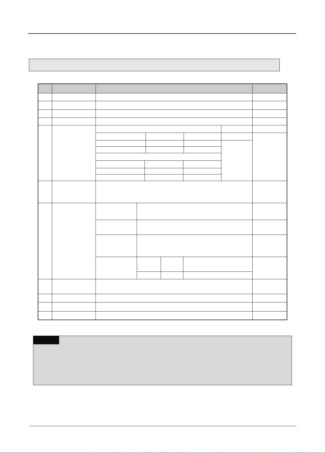
2.2 Performance Specifications
Item
Details
Module Type
Master
Network Type
Profibus-DP
Standard
EN50170/DIN19245
Interface
RS-485 (Electric)
Transmission Route
Bus type
Modulation Type
NRZ
MAC
Local Token Ring
Max. Distance &
Transmission Speed
Distance (m)
Transmission Speed (bps)
1,200
9.6k, 19.2k, 31.25k, 45.45k, 93.75k, 187.5k
400
500k
200
1.5M
100
3M/6M/12M
Max. number of stations per
network
126
Max. number of stations per
segment
32 (including master & repeater)
Max. number of modules per
node
24 modules
Cable used
Electric-twist shielded pair cable
Max. communication size
10 KBytes
Max. size per slave
244 bytes
Max. number of units to be
installed
2MLK-CPUH
2MLI-CPUH
2MLK-CPUS,
CPUA, CPUE
2MLR-CPUH/T, CPUH/F,
CPUH/S
24
24
24
Installation Position
2MLK-CPUH/2MLI-
CPUU
2MLK-CPUS,
CPUA, CPUE
2MLR-CPUH/T, CPUH/F,
CPUH/S
Basic base ~ expansion
stage 7
Basic base ~
expansion stage 3
Stage 31
Communication Parameters
to set
SoftMaster , SyCon (2MLL-PMEA Dedicated Configuration Tool)
N Configurator (2MLL-PMEB/C Dedicated Configuration Tool)
Internal-consumed current
(mA)
550(2MLL-PMEA), 450(2MLL-PMEC), 500(2MLL-PMEB)
Weight (g)
114(2MLL-PMEA), 112(2MLL-PMEC), 88(2MLL-PMEB)
Performance specifications of Pnet I/F module are as described below.
[Table 2.2] Performance Specifications
2 Pnet I/F Module 2MLL-PSRA, 2MLL-PMEA, 2MLL-PMEB User’s Guide R240
Honeywell January 2019
Page 18

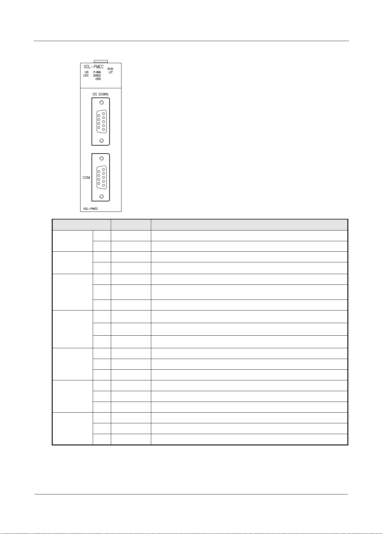
2.3 Structure & Characteristics
LED
Status
LED description
RUN
On
Normal
Completion of initialization
Off
Error
Occurrence of error
I/F
Blink
Normal
Normal status of CPU module and interface
Off
Error
Error of CPU module and interface
HS
On
Normal
Service is normal status when High-speed link is enabled
Blink
Stand by
Communication break status between Pnet I/F module and slave when
downloading by Sycon
Off
Error
High-speed link service error occurred when High-speed link is enabled
P-RUN
Blink
Stop
Stop status of communication status between Pnet I/F module and slave
module
On
Run
Run status of Communication between Pnet I/F module and slave
module
STAT
On
Normal
Normal status of High-speed link communication
Off
Error
Abnormal status of Master module
ERR
On
Error
It needs to check the slave module
Off
Normal
Normal status
◀
LED
display
◀
Connection area of Sycon Configuration Tool
◀
Connection area of communication cable
◀
Designation area
2.3.1 Structure of Pnet I/F module
(1) Structure of 2MLL-PMEA
Chapter 2 Specifications
[Table 2.3.1] LED display of 2MLL-PMEA
3 Pnet I/F Module 2MLL-PSRA, 2MLL-PMEA, 2MLL-PMEB User’s Guide R240
Honeywell January 2019
Page 19
Chapter 2 Specifications
LED
Status
LED description
RUN
On
Normal
Completion of initialization
Off
Error
Occurrence of error
I/F
Blink
Normal
Normal status of CPU module and interface
Off
Error
Error of CPU module and interface
HS
On
Normal
Service is normal status when High-speed link enabled
Blink
Stand by
Communication break status between Pnet I/F module and slave when
downloading by N Configurator
Off
Error
High-speed link service error occurred when High-speed link is enabled
P-RUN
On
Under
communication
Normal communication between the Pnet I/F module and slave
Blink
Under
communication
Clear communication between the Pnet I/F module and slave (I/O data 0)
On
Communication
stop
Communication stop status between the Pnet I/F module and slave
STATUS
On
Error
System error
Blink
Auto-scan
System auto-scan mode
Off
Normal
System normal
ERR
On
Error
Bus error (line short, different communication speed, and etc.)
Blink
Error
There is disconnection during communicating with the slave module
Off
Normal
Normal status
CFG
On
Error
There is no Configuration Setting in the Pnet I/F module
Blink
Normal
Downloading or uploading the Configuration Setting
Off
Normal
A Pnet I/F module is configured normally
◀
LED
display
◀
Firmware Download Port
◀
Connection area of communication cable
◀
Designation area
(2) Structure of 2MLL-PMEC
[Table 2.3.2] LED Display of 2MLL-PMEC
4 Pnet I/F Module 2MLL-PSRA, 2MLL-PMEA, 2MLL-PMEB User’s Guide R240
Honeywell January 2019
Page 20

(3) Structure of 2MLL-PMEB
LED
Status
LED description
RUN
On
Normal
Initialize complete and normal operation
Off
Error
Fatal error
I/F
Blink
Normal
Normal in interface status with CPU
Off
Error
Error in interface status with CPU
HS
On
Normal
Normal HS link communication status
Blink
Standby
Stop communication status/downloading Parameter in HS link enable
Off
Error
HS Link service disable status
P2P
On
Normal
Normal P2P communication status
Blink
Standby
Stop communication status/downloading Parameter in P2P enable
Off
Error
P2P disable status
P-RUN
On
Normal
Normal communication
Off
Error
Communication is stopped
STATUS
On
Error
System error
Off
Normal
Normal communication
ERR
On
Error
All slaves are eliminated
Blink
Error
Some slaves are eliminated
Off
Normal
Normal
CFG
On
Error
No network configuration for Profibus-DP Master module
Blink
Standby
Downloading or uploading configuration parameter to Master module
Off
Normal
Network configuration is installed successfully
◀
Designation area
◀
LED Display
◀
Connection area of communication cable
Chapter 2 Specifications
[Table 2.3.3] LED display of 2MLL-PMEB
5 Pnet I/F Module 2MLL-PSRA, 2MLL-PMEA, 2MLL-PMEB User’s Guide R240
Honeywell January 2019
Page 21

Chapter 2 Specifications
2.4 Cable Specifications
Cable characteristic
Type A
Type B
Impedance
135~160Ω(freq. 3~20MHz)
100~130Ω(freq. > 100kHz)
Capacity
< 30 pF/m
< 60 pF/m
Resistance
< 110 Ω
-
Conductor Area
> 0.34 mm2 (22 AWG)
> 0.22 mm2 (24 AWG)
Baud Rate
(Kbit/s)
9.6
19.2
31.25
45.45
93.75
187.5
500
1500
3000
6000
12000
Cable Type A
1200
1200
1200
1200
1200
1200
400
200
100
100
100
Cable Type B
1200
1200
1200
1200
1200
600
200
70 - -
-
Remark
1) The profibus standard defines two types of bus cables, but it is usually recommended to use a
type. Please contact the cable manufacturer for details.
2) Awg is a numbering scheme that indicates the size of the wire.
2.4.1 Cable Specifications
The cable uses shielded twisted-pair wires. Table 2.4.1 and Table 2.4.2 show the maximum
transmission distance according to cable type and speed cable type.
[Table 2.4.1] Cable specification
[Table 2.4.2] Communication distance by cable and baud rate
6 Pnet I/F Module 2MLL-PSRA, 2MLL-PMEA, 2MLL-PMEB User’s Guide R240
Honeywell January 2019
Page 22

3.1 Precautions for Installation
Item
2MLK
2MLI
2MLR
2MLKCPUH
/CPUU
2MLK-
CPUA
/CPUS
/CPUSN
2MLK-
CPUHN
/CPUUN
2MLK-
CPUE
2MLI-
CPUUN
2MLI-
CPUU
2MLI-
CPUH
2MLI-
CPUS
2MLI-
CPUE
2MLRCPUH/T,
CPUH/F,
CPUH/S
Number of
available
expansion base
(max.)
(Available to
equip
communication
module)
7 3 7
1 7 3 1 31
Chapter 3 Installation and Test Operation
Chapter 3 Installation and Test Operation
3.1.1 Precautions for Installation
For system configuration through Pnet I/F module, carefully make sure of the following items prior to
installation.
1) Check the basic factors necessary for system configuration to select an appropriate communication
module.
2) Select the exclusive Pnet cable to be used for this communication module.
3) Before the communication module is installed, check for any foreign material on the base connector the
module will be installed on and any damage on the connector pin of the module.
4) All the communication modules can be installed on the basic base ~ the expansion base. For the
number of available expansion base by CPU, refer to the following table.
5) For installation of the module, exactly insert the protuberant part at the bottom of the module with the
communication cable disconnected into the base groove and then apply enough strength until its top is
locked up with the locking device of the base. If the lock is not applied, it may cause an error on the
interface with CPU.
1 Pnet I/F Module 2MLL-PSRA, 2MLL-PMEA, 2MLL-PMEB User’s Guide R240
Honeywell January 2019
Page 23

3.2 From Setting to Operation
Operation Sequence
Install Pnet I/F module on the base.
Check the applicable base/slot position for correct installation.
Configure the system between Pnet I/F module and slaves.
Use the exclusive Pnet cable for communication.
Set each slave’s station number
With power On, check the LED status of the communication module.
Check if the interface of the communication module is normal with CPU.(RUN: On, I/F: Blink, ERR:
Off)
Specify the configuration through SyCon or N Configurator.
Specify the module to be configured as Pnet I/F master module and download it.
Download High-speed link/P2P parameters.
Set how to connection with [Online] – [Connection]
[Online] – [Diagnosis] – [I/O information] – [I/O Sync.]
Open the [High-speed Link] block setting tab
Execute [Online] – [Communication module setting] – [Config. Upload] at [High-speed Link] block tab
Set the High-speed Link block parameters
Download the parameters with [Online] – [Write]
Execute [Online] – [Communication module setting] – [Enable Link]
Open [P2P] block setting tab
Set the P2P block parameters
Download the parameters with [Online] – [Write]
Execute [Online] – [Communication module setting] – [Enable Link]
Use system diagnosis function in SOFTMASTER to check the normal operation of the product.
Set how to connection with [Online] – [Connection]
Execute [Online] – [Communication module setting] – [System Diagnosis]
Open the [Status by service] window in [System Diagnosis]
Check the normal operation with P2P and High-speed Link service
Start Run
Chapter 3 Installation and Test Operation
The sequence of the product from installation to operation will be described below. After the product
installation is complete, install and configure the system to be operated as specified in the following
sequence.
2 Pnet I/F Module 2MLL-PSRA, 2MLL-PMEA, 2MLL-PMEB User’s Guide R240
Honeywell January 2019
Page 24
3.3 Installation of the cable
Remark
1) Installation length of Pnet cable depends on the communication speed. (Refer to [Table] 3.2)
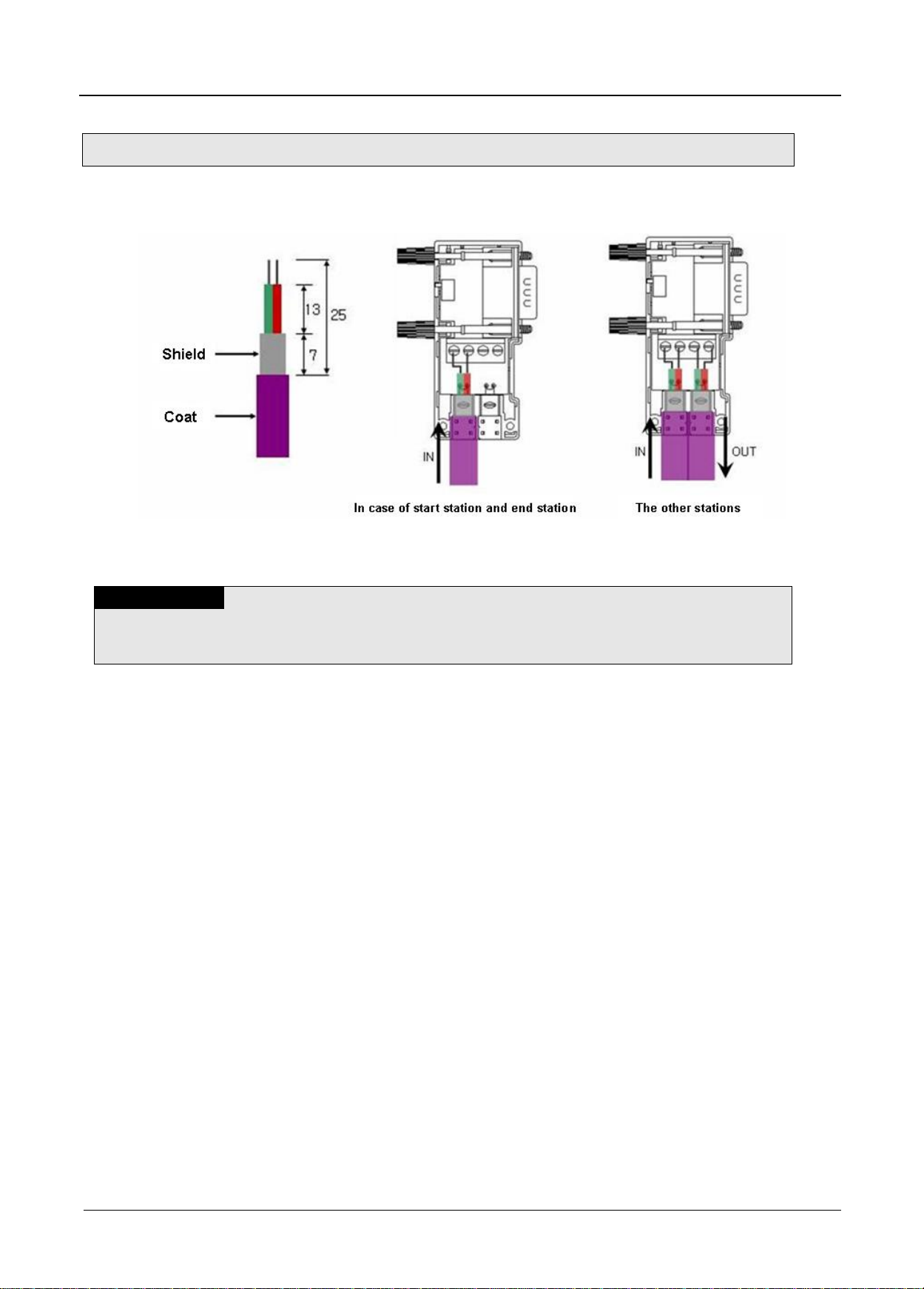
3.3.1 Installation of 2MLL-PMEA/PMEB
Chapter 3 Installation and Test Operation
[Figure 3.3.1] The method of Pnet cable installation
1) How to install Pnet cable
(1) Use Profibus-DP cable.
(2) When slipping the coat of the cable, be careful not to let the shielded line escaped from PCB of
the connector.
(3) The number of stations to be installed shall be within 32 including master and repeater for 1
segment.
(4) The shielded line of the cable shall be in contact with the shielded area of the connector.
(5) The cable is generally recommended to be installed at the end of the slave, diverged from the
master.
(6) If the cable is used at the object car, use the extended line.
(7) Communication cable shall be installed at least 10cm away from the power supply cable.
(8) Check the cable connected with the connector if tightened well with terminal block.
(9) After the cable connected, measure the line resistance value on the master by means of digital
multi-meter. (If terminal resistance at the both ends of the cable is On, it will be generally 110Ω +
line resistance value + connector resistance value)
3 Pnet I/F Module 2MLL-PSRA, 2MLL-PMEA, 2MLL-PMEB User’s Guide R240
Honeywell January 2019
Page 25
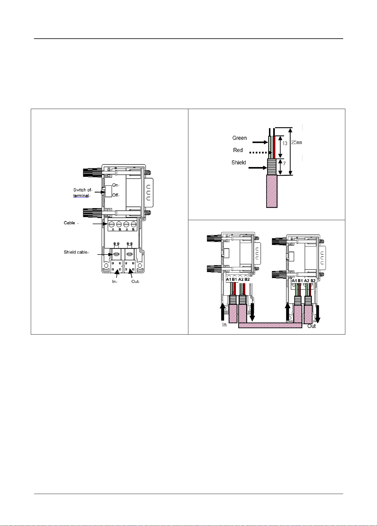
<Connector structure>
<Cable structure>
<Cable wiring method>
Chapter 3 Installation and Test Operation
2) Pnet Connector structure and wiring method
(1) Input Line: green line is connected to A1, red line is connected to B1
(2) Output line: green line is connected to A2, red line is connected to B2
(3) Connect shield to clamp of shield
(4) In case of installing the connector at terminal, install the cable at A1, B1
4 Pnet I/F Module 2MLL-PSRA, 2MLL-PMEA, 2MLL-PMEB User’s Guide R240
Honeywell January 2019
Page 26

Remark
(1) Please refer to below for cable name and place of purchase.
1) Thomascable : Profibus-DP UNITRONIC-BUS L2/FIP/BUS Tel)043-217-8600
2) Belden cable : 3079A Tel)02-2202-2656
Chapter 3 Installation and Test Operation
3) Pnet termination
- Connector
<Terminal connection> <Branch connection>
4) General notices
(1) Termination treatment of vertical section is needed.
(2) In case that the distance is far between stations, it is possible to extend the segment through
repeater(max. 9 repeater, 10 segment), available to connect 32 stations per segment(include
repeater), max. 126 stations. (Repeater does not have station no.) The extended segment
having no station is available.
(3) Shield shall be connected to the housing of connector.
(4) Use the special connector having the inductor inside.
(5) Spur Line is not allowed to use.
(6) If the ground potential difference between stations is big, a great amount of current may flow
through the shield. In this case, install the cable to make the ground potential difference equal
separately. For high speed more than 1.5Mbps, special cares should be taken.
(7) In case of 12Mbps, keep the distance more than 1m between stations.
5) Termination treatment
(1) Each segment should do the termination treatment for both ends. If there are several segments,
it is required to do the termination treatment for each segment.
(2) Termination is available to turn on/off by the switch of special connector.
(3) If possible, install the master at the end of one side.
5 Pnet I/F Module 2MLL-PSRA, 2MLL-PMEA, 2MLL-PMEB User’s Guide R240
Honeywell January 2019
Page 27

3.4 Test Operation
Chapter 3 Installation and Test Operation
Terminal resistance switch of Pnet cable shall be On. If the switch is not On, communication errors may
occur. Check LED operation status if normal with power on after communication cable is connected. If
normal, download the applicable program to PLC via SOFTMASTER so to execute the program.
3.4.1 Precautions for system configuration
1) Station No. of each slave shall be surely different from each other including this module. If connected
with the repeated station No., communication error may occur, leading to communication trouble.
High-speed link station No. of all stations also shall be different from each other to use High-speed
link service.
2) Use the communication cable as specified only. If not, serious error may occur to communication.
3) Check communication cable if disconnected or shorted prior to installation.
4) Tighten up communication cable connector until connected firmly. If cable connection is unstable, serious
error may occur to communication.
5) If remote communication cable is connected, keep the cable far away from power line or inductive noise.
6) Since the coaxial cable is not flexible, it is to be diverged min. 30cm away from the connector in
communication module. If the cable is bent at a right angle or transformed compulsorily, cable
disconnection or connector damage in communication module will be caused.
7) If LED operation is abnormal, refer to Chapter 10 Troubleshooting to check for causes and take actions
against. Contact service center if the error is as before.
6 Pnet I/F Module 2MLL-PSRA, 2MLL-PMEA, 2MLL-PMEB User’s Guide R240
Honeywell January 2019
Page 28
Chapter 4 System Configuration
4.1 System Configuration of Network
Chapter 4 System Configuration
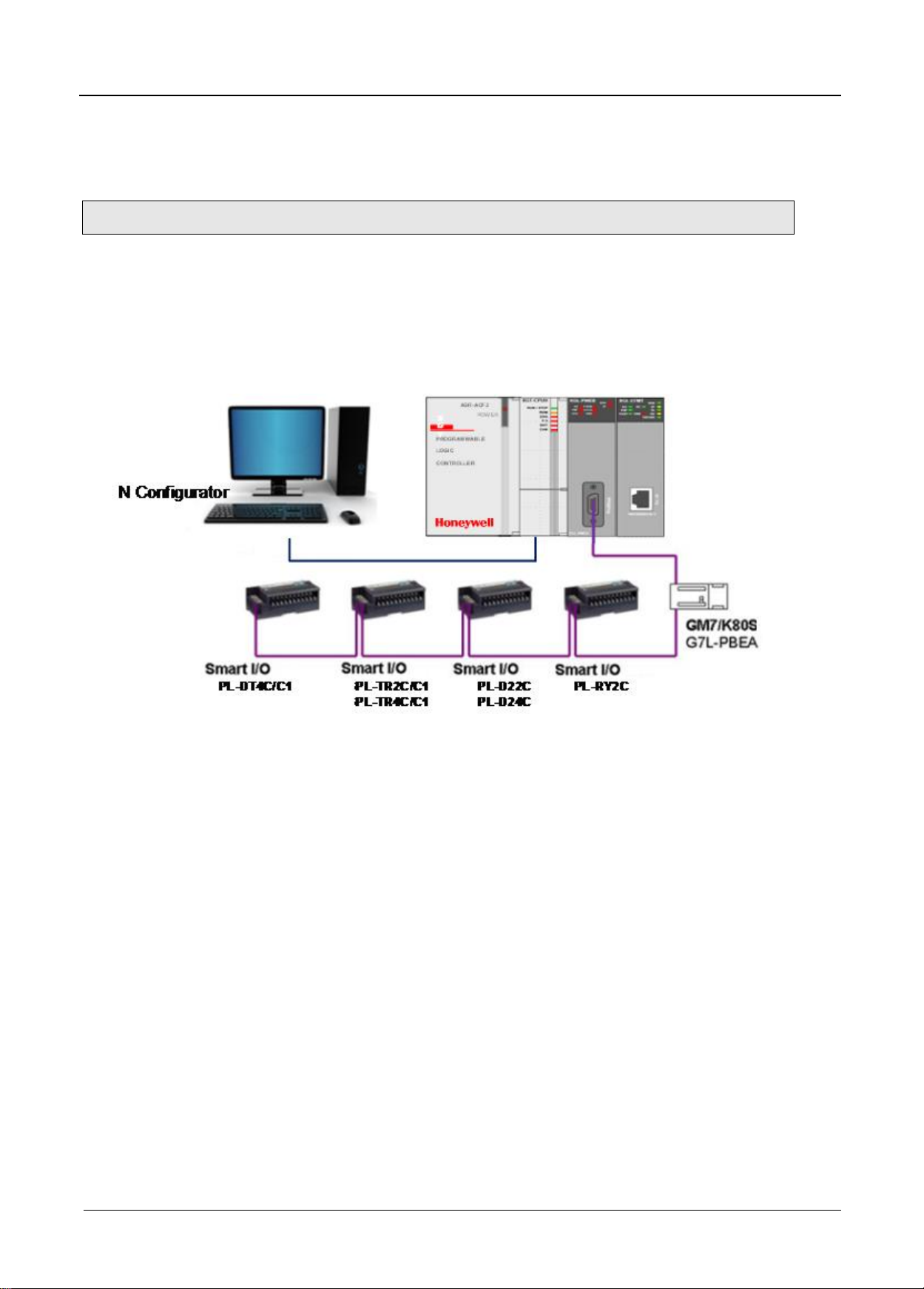
4.1.1 ML200 Pnet module and Smart I/O
Communication system of Pnet I/F modules is as shown below.
Set the Pnet I/F module as master in system and the others have to set as slave module.
To connect LS inverter, Pnet I/F option module have to install applicable product then it will be communicate.
[Figure 4.1] ML200 Pnet + Smart I/O diagram
1 Pnet I/F Module 2MLL-PSRA, 2MLL-PMEA, 2MLL-PMEB User’s Guide R240
Honeywell January 2019
Page 29
Chapter 4 System Configuration
Sensor
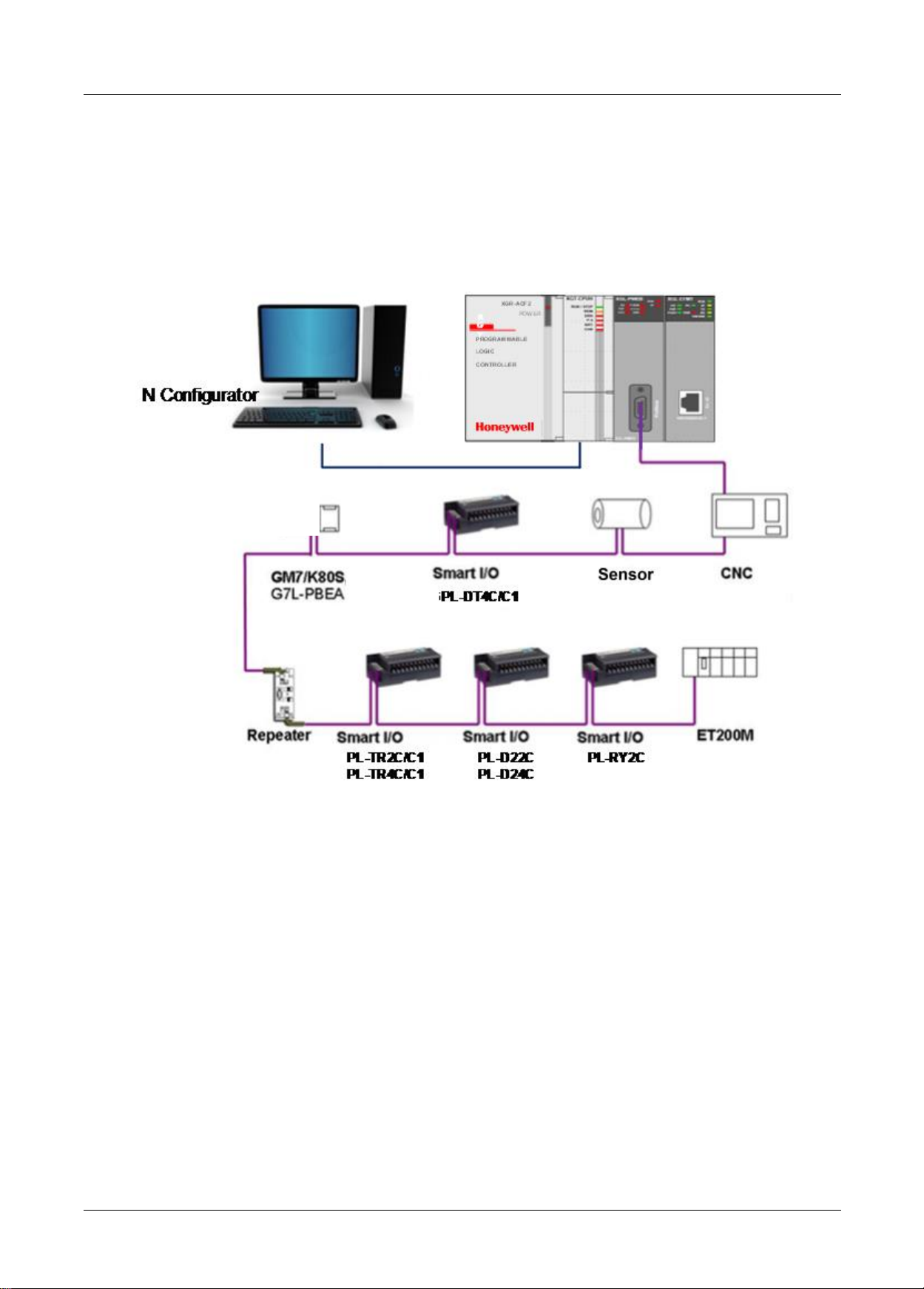
4.1.2 ML200 Pnet + Composite System
If it is used with another company product, GSD file provided by the maker is needed. After GSD file is copied
to GSD folder of Pnet configuration software tool(SYCON, N Configurator) and then if you use Pnet
configuration software tool(SYCON, N Configurator), you can configure the slave modules in the network
automatically.
[Figure 4.1.2] ML200 Pnet + Composite system Diagram
2 Pnet I/F Module 2MLL-PSRA, 2MLL-PMEA, 2MLL-PMEB User’s Guide R240
Honeywell January 2019
Page 30

Chapter 5 Communication Program
5.1 Communication Program
Note
(1) How to set SoftMaster is same though CPU type is different.
1) CPU type: 2MLI, 2MLK, 2MLR system common
(2) P2P communication is available with 2MLL-PMEB only that supports PROFIBUS DPv1.
Chapter 5 Communication Program
There is one communication function available in Pnet I/F module as described below.
5.1.1 Type of communication program
(1) High-speed link
High-speed link as a communication method between ML200 PLC communication module and slave
module is used to exchange data or information with destination station periodically for a specific time,
through which the changed data of self station or the destination station can be referred to periodically
for efficient application to the operation system and execution of communication is available only with
simple parameters setting.
How to set parameter is, download the configuration data to the communication module by means of
“Pnet configuration tool. And then upload the downloaded file in the SoftMaster. And then, specify the
self station area and destination station area for sending/receiving in the high speed link parameter.
Download the specified parameters and let the link enabled to execute High-speed link communication.
Data size is available from the min. 1 byte (16 points) to 244 bytes for the communication,
communication period from the min. 20 ms up to 10 sec. based on the communication details. It is easy
to use because communication with destination station is available only through simple parameters
setting. And it is also useful for periodic process of lots of data at a time thanks to high processing
speed of the internal data.
(2) P2P
P2P is the communication method between ML200 PLC communication module and slave module. It
can be used to read/write the data or information of slave at the point in time.
It can be effectively used to exchange the status information of other station or handle the alarm by
simple parameter settings.
How to set the parameter is as below,
1) In P2P parameter of SoftMaster, select data sending direction or alarm handling function.
2) Set slave’s station number and data address, ML200 PLC communication module address,
condition flag.
3) Download the P2P parameter and enable the link. Then P2P communication will be start.
Maximum 244 bytes sending and receiving data are available. It operates by condition flag that makes
it useful when user handle the temporary data.
(3) Configuration tool
In order to use a Pnet I/F module, you have to configure the system by ‘SyCon’ and ‘N
confugurator’ configuration tool and then download it to the Pnet I/F module
For detail on the setting method, refer to how to set the configuration tool
1 Pnet I/F Module 2MLL-PSRA, 2MLL-PMEA, 2MLL-PMEB User’s Guide R240
Honeywell January 2019
Page 31

Chapter 5 Communication Program
5.2 SoftMaster pragram
In order to use Pnet I/F module, set High-speed link parameters (after SyCon/N Configurator Configuration is
uploaded) and then download the specified parameters onto CPU for application, which is available through
the SoftMaster.
5.2.1 Setting PLC type
To connect the SoftMaster to the PLC, you have to set the PLC type. Create the new project by selecting
[File] [New File]. On the new project menu, input the project name, project type and PLC type as shown
below
[Fig. 5.2.1] is initial screen of the SoftMaster
2 Pnet I/F Module 2MLL-PSRA, 2MLL-PMEA, 2MLL-PMEB User’s Guide R240
Honeywell January 2019
[Figure 5.2.1] initial screen of the SoftMaster
Page 32

Chapter 5 Communication Program
Items
Contents
Remark
Project name
Writing the project name in the SoftMaster software.
File location
Selecting the directory to save the project.
PLC Series
Selecting the PLC series (2MLK, ML50, 2MLI, 2MLR)
CPU kind
2MLK
2MLK-CPUA, CPUE, CPUH, CPUS, CPUU
ML50
ML50-MLMS, MLCH, MLIH, MLIE,
2MLI
2MLI-CPUU, CPUU/D, CPUH, CPUE, CPUS
2MLR
2MLR-CPUH/T, 2MLR-CPUH/F
Project comment
Writing the comment about the project.
[Figure 5.2.2] Creation of new project
There are 4 types of PLC (2MLK, ML50, 2MLI, and 2MLR). For detail on the CPU, refer to CPU
manual. Here we select 2MLK for example. After setting, menu of [Figure 5.2.3] appears
3 Pnet I/F Module 2MLL-PSRA, 2MLL-PMEA, 2MLL-PMEB User’s Guide R240
Honeywell January 2019
Page 33

Chapter 5 Communication Program
[Figure 5.2.3] Initial menu of SoftMaster
5.2.2 Registration of the communication module
This describes on the basic setting needed for operation of Pnet I/F module
(1) Selection of the communication module
For the basic setting of the communication module in the SoftMaster, you have to register the
communication module at the applicable base, slot position of Standard setting window. You
can register the communication in the both ON/OFF status.
1) Registration in the offline status
If you want to register the communication without connection, select the base and slot of
standard setting window. Registration example of base 0, slot 2 is as follow.
a) Right click [Unspecified Network] in project tree and select
[Add Item] -> [Communication module]
4 Pnet I/F Module 2MLL-PSRA, 2MLL-PMEA, 2MLL-PMEB User’s Guide R240
Honeywell January 2019
Page 34

Chapter 5 Communication Program
[Figure 5.2.4] Communication module menu selecting
b) Click [Add module] in [Select Communication Module] window.
[Figure 5.2.5] Add module
c) Select the type, base and slot in [Communication Module Settings] window.
[Figure 5.2.6] Communication module setting
5 Pnet I/F Module 2MLL-PSRA, 2MLL-PMEA, 2MLL-PMEB User’s Guide R240
Honeywell January 2019
Page 35

Chapter 5 Communication Program
Classification Description
Communication
module setting
Type
Pnet I/F module
Base
Base no. of mounted module
Slot
Slot no. of mounted module
Pnet I/F module Off-line registration on base 0, slot 2 is as follow
[Table 5.2.1] Communication module setting contents
Registration PMEB module on base 0, slot 2
[Figure 5.2.7] Registration screen
6 Pnet I/F Module 2MLL-PSRA, 2MLL-PMEA, 2MLL-PMEB User’s Guide R240
Honeywell January 2019
Page 36

Chapter 5 Communication Program
2) Registration in the online status
Connect to the ML200 CPU module. After connection, if you select [Online]-[Diagnosis]-[I/O
Information…], then click “I/O Sync], it searches all communication module and register them
automatically
* PLC should be STOP status for I/O Sync
[Figure 5.2.6] Read IO Information
In case Pnet is installed at the base 0, slot 10, it searches and registers as follows.
[Figure 5.2.7] Basic setting and Communication module Settings screen
7 Pnet I/F Module 2MLL-PSRA, 2MLL-PMEA, 2MLL-PMEB User’s Guide R240
Honeywell January 2019
Page 37

Chapter 5 Communication Program
5.2.3 Uploading High Speed Link parameter and setup
(1) Screen of communication module specified
[Figure 5.2.9] Communication Module Settings
(2) Uploading a configuration tool (SyCon or N-Configurator)
With the mouse cursor positioned on “High-speed link1”, select [Online]-[Communication module
setting]-[Config. Upload (Dnet, Pnet)]
[Figure 5.2.10] Config data Upload from SyCon or N-Congurator
8 Pnet I/F Module 2MLL-PSRA, 2MLL-PMEA, 2MLL-PMEB User’s Guide R240
Honeywell January 2019
Page 38

Chapter 5 Communication Program
Classification
Details
Master
Station No.
Display the Master station no.
Station No. *1
Setting range for the slave : 0 ~ 126
If identical station No. is set, communication will not be normal.
Mode *1
Sending: Transmission the data from master module to slave module.
Receiving: Transmission the data from slave module to master module.
Read area
(Master module
→
Slave module)
2MLK
Area to set the start address of device used for Sending.
Setting device : P, M, K, F, T, C, U, Z, L, N, D, R, ZR
2MLI
Area to set the start address of device used for Sending.
Setting device : A, M, I, Q, R, W, F, K, L, N, U
Save area
(Slave module
→
Master module)
2MLK
Area to set the start address of device used for Receiving.
Setting device : P, M, K, F, T, C, U, Z, L, N, D, R, ZR
2MLI
Area to set the start address of device used for Receiving.
Setting device : A, M, I, Q, R, W, F, K, L, N, U
Send data
Receive data
(Byte)
Display input/output points of slave module by the bytes.
- In case of I/O module of 8 bits or less, please s et 1 byte.
(3) Screen after “SyCon Upload”
[Figures 5.2.11] Screen after SyCon uploaded
(4) High-speed link parameter settings
*1 : Area is not able to set
[Table 5.2.2] High-speed link Block Settings
9 Pnet I/F Module 2MLL-PSRA, 2MLL-PMEA, 2MLL-PMEB User’s Guide R240
Honeywell January 2019
Page 39

Chapter 5 Communication Program
(5) High-speed link parameters download
[Figure 5.2.12] High-speed link parameters download
(6) Enabling the Link
[Figure 5.2.13] Link Enable of High-speed link parameters
10 Pnet I/F Module 2MLL-PSRA, 2MLL-PMEA, 2MLL-PMEB User’s Guide R240
Honeywell January 2019
Page 40

Item
Description
P2P function
Write, read, diagnostic
Condition flag
Condition flag
Data type*1
Data type
No. of variable*1
No. of variable
Destination station
Check destination station
No. of destination
station
Destination station
Setting
Read area
Sending data area
Save area
Save area of receiving data
Data size
Sending/Receiving data size
5.2.4 P2P Parameter Setting
(1) The screen after communication module setting is as follow
Chapter 5 Communication Program
[Figure 5.2.14] The screen after communication module setting
(2) P2P parameter setting
*1 isn’t setting area.
[Table 5.2.15] P2P block setting
11 Pnet I/F Module 2MLL-PSRA, 2MLL-PMEA, 2MLL-PMEB User’s Guide R240
Honeywell January 2019
Page 41

Chapter 5 Communication Program
(5) Download P2P parameter
[Figure 5.2.16] P2P parameter download
(6) Enable link
[Figure 5.2.17] Enable link P2P parameter
12 Pnet I/F Module 2MLL-PSRA, 2MLL-PMEA, 2MLL-PMEB User’s Guide R240
Honeywell January 2019
Page 42

Chapter 5 Communication Program
Item
Version
SoftMaster
V3.61 or above
2MLR CPU
V1.91 or above
2MLI CPU
V3.4 or above
2MLK CPU
V3.7 or above
Flag
Data type
Device
Description
_HS_ENABLE_STATE
ARRAY[0..11] OF BOOL
%FX19040
HS link enable/disable current state
_HS_REQ
ARRAY[0..11] OF BOOL
%FX31520
HS link enable/disable request
_HS_REQ_NUM
ARRAY[0..11] OF BOOL
%FX31536
HS link enable/disable setting
_P2P_ENABLE_STATE
ARRAY[0..7] OF BOOL
%FX19072
P2P enable/disable current state
_P2P_REQ
ARRAY[0..7] OF BOOL
%FX31552
P2P enable/disable request
_P2P_REQ_NUM
ARRAY[0..7] OF BOOL
%FX31568
P2P enable/disable setting
Flag
Data type
Device
Description
_HS_ENABLE_STATE
ARRAY[0..11] OF BOOL
%FX15840
HS link enable/disable current state
_HS_REQ
ARRAY[0..11] OF BOOL
%FX16480
HS link enable/disable request
_HS_REQ_NUM
ARRAY[0..11] OF BOOL
%FX16496
HS link enable/disable setting
_P2P_ENABLE_STATE
ARRAY[0..7] OF BOOL
%FX15872
P2P enable/disable current state
_P2P_REQ
ARRAY[0..7] OF BOOL
%FX16512
P2P enable/disable request
_P2P_REQ_NUM
ARRAY[0..7] OF BOOL
%FX16528
P2P enable/disable setting
Flag
Data type
Device
Description
_HS1_ENABLE_STATE
BIT
F09600
HS link 1 enable/disable current state
_HS2_ENABLE_STATE
BIT
F09601
HS link 2 enable/disable current state
_HS3_ENABLE_STATE
BIT
F09602
HS link 3 enable/disable current state
_HS4_ENABLE_STATE
BIT
F09603
HS link 4 enable/disable current state
_HS5_ENABLE_STATE
BIT
F09604
HS link 5 enable/disable current state
_HS6_ENABLE_STATE
BIT
F09605
HS link 6 enable/disable current state
_HS7_ENABLE_STATE
BIT
F09606
HS link 7 enable/disable current state
_HS8_ENABLE_STATE
BIT
F09607
HS link 8 enable/disable current state
_HS9_ENABLE_STATE
BIT
F09608
HS link 9 enable/disable current state
_HS10_ENABLE_STATE
BIT
F09609
HS link 10 enable/disable current state
_HS11_ENABLE_STATE
BIT
F0960A
HS link 11 enable/disable current state
_HS12_ENABLE_STATE
BIT
F0960B
HS link 12 enable/disable current state
_HS1_REQ
BIT
F10300
HS link 1 enable/disable request
_HS2_REQ
BIT
F10301
HS link 2 enable/disable request
_HS3_REQ
BIT
F10302
HS link 3 enable/disable request
_HS4_REQ
BIT
F10303
HS link 4 enable/disable request
_HS5_REQ
BIT
F10304
HS link 5 enable/disable request
_HS6_REQ
BIT
F10305
HS link 6 enable/disable request
_HS7_REQ
BIT
F10306
HS link 7 enable/disable request
_HS8_REQ
BIT
F10307
HS link 8 enable/disable request
_HS9_REQ
BIT
F10308
HS link 9 enable/disable request
_HS10_REQ
BIT
F10309
HS link 10 enable/disable request
_HS11_REQ
BIT
F1030A
HS link 11 enable/disable request
_HS12_REQ
BIT
F1030B
HS link 12 enable/disable request
_HS1_REQ_NUM
BIT
F10310
HS link 1 enable/disable setting
_HS2_REQ_NUM
BIT
F10311
HS link 2 enable/disable setting
_HS3_REQ_NUM
BIT
F10312
HS link 3 enable/disable setting
_HS4_REQ_NUM
BIT
F10313
HS link 4 enable/disable setting
_HS5_REQ_NUM
BIT
F10314
HS link 5 enable/disable setting
* Enable Link through flag
It describes “Enable Link” method through flag. The following SoftMaster version, CPU OS version is needed.
Flag list related with “Enable Link”
-2MLR
-2MLI
-2MLK
13 Pnet I/F Module 2MLL-PSRA, 2MLL-PMEA, 2MLL-PMEB User’s Guide R240
Honeywell January 2019
Page 43

Chapter 5 Communication Program
Flag
Data type
Device
Description
_HS6_REQ_NUM
BIT
F10315
HS link 6 enable/disable setting
_HS7_REQ_NUM
BIT
F10316
HS link 7 enable/disable setting
_HS8_REQ_NUM
BIT
F10317
HS link 8 enable/disable setting
_HS9_REQ_NUM
BIT
F10318
HS link 9 enable/disable setting
_HS10_REQ_NUM
BIT
F10319
HS link 10 enable/disable setting
_HS11_REQ_NUM
BIT
F1031A
HS link 11 enable/disable setting
_HS12_REQ_NUM
BIT
F1031B
HS link 12 enable/disable setting
_P2P1_ENABLE_STATE
BIT
F09620
P2P1 enable/disable current state
_P2P2_ENABLE_STATE
BIT
F09621
P2P2 enable/disable current state
_P2P3_ENABLE_STATE
BIT
F09622
P2P3 enable/disable current state
_P2P4_ENABLE_STATE
BIT
F09623
P2P4 enable/disable current state
_P2P5_ENABLE_STATE
BIT
F09624
P2P5 enable/disable current state
_P2P6_ENABLE_STATE
BIT
F09625
P2P6 enable/disable current state
_P2P7_ENABLE_STATE
BIT
F09626
P2P7 enable/disable current state
_P2P8_ENABLE_STATE
BIT
F09627
P2P8 enable/disable current state
_P2P1_REQ
BIT
F10320
P2P1 enable/disable request
_P2P2_REQ
BIT
F10321
P2P2 enable/disable request
_P2P3_REQ
BIT
F10322
P2P3 enable/disable request
_P2P4_REQ
BIT
F10323
P2P4 enable/disable request
_P2P5_REQ
BIT
F10324
P2P5 enable/disable request
_P2P6_REQ
BIT
F10325
P2P6 enable/disable request
_P2P7_REQ
BIT
F10326
P2P7 enable/disable request
_P2P8_REQ
BIT
F10327
P2P8 enable/disable request
_P2P1_REQ_NUM
BIT
F10330
P2P1 enable/disable setting
_P2P2_REQ_NUM
BIT
F10331
P2P2 enable/disable setting
_P2P3_REQ_NUM
BIT
F10332
P2P3 enable/disable setting
_P2P4_REQ_NUM
BIT
F10333
P2P4 enable/disable setting
_P2P5_REQ_NUM
BIT
F10334
P2P5 enable/disable setting
_P2P6_REQ_NUM
BIT
F10335
P2P6 enable/disable setting
_P2P7_REQ_NUM
BIT
F10336
P2P7 enable/disable setting
_P2P8_REQ_NUM
BIT
F10337
P2P8 enable/disable setting
▶ How to enable link
-HS link/P2P enable/disable setting flag ON HS link/P2P enable/disable request flag ON
▶ How to disable link
-HS link/P2P enable/disable setting flag OFF HS link/P2P enable/disable request flag ON
▶ You can monitor the Enable/Disable state of the each link through “enable/disable current states” flag.
14 Pnet I/F Module 2MLL-PSRA, 2MLL-PMEA, 2MLL-PMEB User’s Guide R240
Honeywell January 2019
Page 44

Chapter 5 Communication Program
(7) Read
(a) Connect to CPU.
(b) After connected, select On-line and Read Parameter to display the screen as shown in [Figure.
5.2.16] and then, check the applicable parameters and click [OK].
[Figure 5.2.14] Read screen
(c) Reads previously specified values for the parameters checked.
(8) View Tree by Transmission/Reception
15 Pnet I/F Module 2MLL-PSRA, 2MLL-PMEA, 2MLL-PMEB User’s Guide R240
Honeywell January 2019
Page 45

Chapter 5 Communication Program
16 Pnet I/F Module 2MLL-PSRA, 2MLL-PMEA, 2MLL-PMEB User’s Guide R240
Honeywell January 2019
Page 46

6.1 Introduction
Function
Section
Details
Configuration
Communication type
Communication type and its details
Automatic network scan
Network scan
Diagnostic
Diagnostic function
Live List, Debugger, Global State Field
User data Send
I/O monitor, I/O monitor
Documentation
Print
Print out the Configuration
6.2 Installation
Chapter 6 SyCon Setting
6.1.1 Main functions
Chapter 6 SyCon Setting
6.1.2 Characteristics
SyCon is a Global Fieldbus Configurator.
SyCon executes the configuration through a standardized file.
SyCon has a diagnosis function.
6.2.1 System requirements
▪ PC 486 or higher
▪ Windows 95/98/ME/NT/2000/XP or later version
▪ Hard disc with 80MB or more
▪ CD ROM Drive
▪ RAM with 16MB or more
▪ Graphic Resolution: min. 800 x 600 pixel
▪ Windows 95: Service Pack 1 or higher
▪ Windows NT: Service Pack 3 or higher
1 Pnet I/F Module 2MLL-PSRA, 2MLL-PMEA, 2MLL-PMEB User’s Guide R240
Honeywell January 2019
Page 47

Chapter 6 SyCon Setting
Select System
Installation
Select here
6.2.2 Software installation
1) After the CD is inserted into CD-ROM, Execute ‘Autorun.exe’.
2. Select ‘System installation’ and execute.
1) Do you want to install the System Configurator SyCon? Yes
2) Do you want to install the SyCon integrated OPC Server? No
3) Do you want to the Stand-Alone OPC Server/Busserver? No
4) Do you have a License code? Yes
5) Select Language
Next
2 Pnet I/F Module 2MLL-PSRA, 2MLL-PMEA, 2MLL-PMEB User’s Guide R240
Honeywell January 2019
Page 48

Chapter 6 SyCon Setting
3. License Agreement
Select I agree
4. Program Registration
Input License code: F90BF4B3E874
Select ‘OK’
Select ‘Yes’.
3 Pnet I/F Module 2MLL-PSRA, 2MLL-PMEA, 2MLL-PMEB User’s Guide R240
Honeywell January 2019
Page 49

Chapter 6 SyCon Setting
5. Configuration Setup
Select ‘Next’.
4 Pnet I/F Module 2MLL-PSRA, 2MLL-PMEA, 2MLL-PMEB User’s Guide R240
Honeywell January 2019
Page 50

Chapter 6 SyCon Setting
Select the destination folder
to install
Display minimum Disk Space
required of PC
Select Network to install
1) Components
Select ‘Next’
2) Program Folder
Select ‘Next’
5 Pnet I/F Module 2MLL-PSRA, 2MLL-PMEA, 2MLL-PMEB User’s Guide R240
Honeywell January 2019
Page 51

Chapter 6 SyCon Setting
3) Setup complete
6. Installed contents
1) Installed file
6 Pnet I/F Module 2MLL-PSRA, 2MLL-PMEA, 2MLL-PMEB User’s Guide R240
Honeywell January 2019
Page 52

Chapter 6 SyCon Setting
2) Contents of Folder
- Destination: C:\Program Files\Honeywell\SyCon
3) GSD files for Profibus
- GSD files are generated as shown below.
7 Pnet I/F Module 2MLL-PSRA, 2MLL-PMEA, 2MLL-PMEB User’s Guide R240
Honeywell January 2019
Page 53

Chapter 6 SyCon Setting
6.3 Communication Settings in SyCon
Menu
Icon
Status
Menu
Icon
Status
6.3.1 Initial screen
Network
Edit
8 Pnet I/F Module 2MLL-PSRA, 2MLL-PMEA, 2MLL-PMEB User’s Guide R240
Honeywell January 2019
Page 54

Main
Submenu
Description
File
New
Make new file
Open
Open existed file
Close
Close the open file
Save
Save the open file
Save As
Saving the file as another name
Export
Export to Project
Copy
EDS
DBM
Import DBM extension file
PDD
Import PDD extension file
CSV
Import CSV extension file
GSD
DBM
Import DBM extension file
CSV
Import CSV extension file
Print…
Print
Print Preview
Preview of print
Print Setup…
Setup of print
Recent File
Display of recent file list
Exit
Exit SyCon
Editer
Cut
Cutting
Copy
copying
Paste
Pasting
Delete
Deleting
Replace
Replace
View
Device Table
Display of device name, ID and Type
Address Table
Display of slave module address and Size of
Input/Output
Logical Network View
-
Toolbars
Standard
Activate the basic menu
Fieldbus
Activate the Insert Icon on menu
Status Bar
Display the Status Bar on SyCon basic window
Insert
Master
Insert Master module
Device
Insert Slave module
6.3.2 Composition of menu
Chapter 6 SyCon Setting
9 Pnet I/F Module 2MLL-PSRA, 2MLL-PMEA, 2MLL-PMEB User’s Guide R240
Honeywell January 2019
Page 55

Chapter 6 SyCon Setting
Main
Submenu
Description
Online
Download
Downloading SyCon settings file
Start Debug Mode
Display current connection status
Device Diagnostic
Information of diagnosis saved
Firmware Download
Downloading by Firmware
Firmware/Reset
Reset the Firmware
Extended Device Diagnostic
Function of diagnosis extended
Global State Field
Status of current communication and moue
Live List
Information and status of module per
station number
I/O Monitor
Display of I/O data
Message Monitor
Data analyzing between Master and Slave
Automatic Network Scan
Setting the network automatically
Get Device Attribute/
Set Device Attribute
-
Start Communication
Run the communication
Stop Communication
stop the communication
Device Info
Display of the day of manufacture and
Serial number
Activate Driver
To register the unregistered device
Read project Information
Information of project
Settings
Device Assignment
Setup the way of communication with Host
Bus Parameters
Setting of communication speed and
various parameter
Master Settings
Setting of master
Device Settings
-
Device Configuration
-
Auto Addressing
To allocate the address automatically
Project Information
Information of project
Path
The path of GSD setting file and project
Language
Language selection
Window
Cascade
Window array to cascade
Tile
Window array to tile
Help
Help Topics
Help view
About
Information of SyCon program
10 Pnet I/F Module 2MLL-PSRA, 2MLL-PMEA, 2MLL-PMEB User’s Guide R240
Honeywell January 2019
Page 56

Master type
GSD File Name
Master name
ML200
2MLL-PMEA
HIL_069E
COM-C-DPM
GM/MK
G3L-PUEA
G4L-PUEA
G6L-PUEA
HIL_7065
COM-DPM/PKV20-DPM
G3L-PUEB
G4L-PUEB
G6L-PUEB
HIL_1662
COM-PB/PKV-PB
6.3.3 New file
1) Selection of Fieldbus
Chapter 6 SyCon Setting
2) The composition of picture
3) Master selection
11 Pnet I/F Module 2MLL-PSRA, 2MLL-PMEA, 2MLL-PMEB User’s Guide R240
Honeywell January 2019
Page 57

Chapter 6 SyCon Setting
Method
Selection order
Execution Icon
Menu
Insert → Master
Icon
Master type
GSD File Name
Master name
ML200
2MLL-PMEA
HIL_069E
COM-C-DPM
GM/MK
G3L-PUEA
G4L-PUEA
G6L-PUEA
HIL_7065
COM-DPM/PKV20-DPM
G3L-PUEB
G4L-PUEB
G6L-PUEB
HIL_1662
COM-PB/PKV-PB
6.3.4 Master selection
1) Selection
2) Insert
12 Pnet I/F Module 2MLL-PSRA, 2MLL-PMEA, 2MLL-PMEB User’s Guide R240
Honeywell January 2019
Page 58

Chapter 6 SyCon Setting
3) Edit
4) Master Configuration
- Select “Settings” “Master Configuration” on menu.
13 Pnet I/F Module 2MLL-PSRA, 2MLL-PMEA, 2MLL-PMEB User’s Guide R240
Honeywell January 2019
Page 59

Chapter 6 SyCon Setting
Item
Description
General
Description
Explain of Master
Station address
Setting of Master station number
Device
Display of Master board
DP Support
DP Master Settings
Setting of DP Master
FMS Support
It is set when the device supports the FMS
5) DP Master settings
a) Set the “Controlled release of the communication by the application program” in “Parameter to user
interface”
b) Set “1000ms” in “User program monitoring”
c) “Parameter to process data interface”
(a) Set “Byte addresses” in “Addressing mode”
(b) Set “Little Endian” in “Storage format(word module)”
d) Set “Buffered, host controlled” in “Handshake of the process data”
14 Pnet I/F Module 2MLL-PSRA, 2MLL-PMEA, 2MLL-PMEB User’s Guide R240
Honeywell January 2019
Page 60

Method
Selection order
Execution Icon
Menu
Insert → Slave
Icon
Item
Description
Slave Filter
Vendor
Slave maker (Allen Bradley, Siemens..)
Slave type
Drive unit, I/O-Slave…
Available slaves
Display of Slave module in GSD folder
(MPL-D22A, MPL-TR2C…)
Master
Display of Master device and station number
Selected slaves
Display of slave module designated
Station address
Display of Slave module station number (It must not
duplicate)
Description
Explain of Slave module (It must not duplicate)
Slave selection
6.3.5 Slave selection
It is executed after master inserted.
1) Select
Chapter 6 SyCon Setting
2) Insert
15 Pnet I/F Module 2MLL-PSRA, 2MLL-PMEA, 2MLL-PMEB User’s Guide R240
Honeywell January 2019
Page 61

Chapter 6 SyCon Setting
Slave type
GSD
File Name
Slave name
Remark
PLC
DC input 16 points
MPL_D22A
MPL-D22A
Fixed Terminal Block
HNWL07B1
MPL-D22A/C
Fixed/Removable Terminal Block
DC input 32 points
MPL_D24A
MPL-D24A
Fixed Terminal Block
HNWL07B2
MPL-D24A/C
Fixed/Removable Terminal Block
DC input 16 points
Tr output 16 points
MPL_DT4A
MPL-DT4A
Fixed Terminal Block
HNWL07B3
MPL-DT4A/B/C
Fixed/Removable Terminal Block
Relay output 16 points
MPL_RY2A
MPL-RY2A
Fixed Terminal Block
HNWL07B6
MPL-RY2A/C
Fixed/Removable Terminal Block
Tr output 16 points
MPL_TR2A
MPL-TR2A
Fixed Terminal Block
HNWL07B4
MPL-TR2A/B/C
Fixed/Removable Terminal Block
Tr output 32 points
MPL_ TR4A
MPL-TR4A
Fixed Terminal Block
HNWL07B5
MPL-TR4A/B/C
Fixed/Removable Terminal Block
Analog input
HNWL09F8
MPL-AC8C
8channel, Current Input
HNWL09FB
MPL-AV8C
8channel, Voltage Input
Analog output
HNWL09FC
MPL-DV4C
4channel, Voltage Output
HNWL09FE
MPL-DC4C
4channel, Current Output
Module type slave
HNWL7100
GLOFA GM7
Slave Adapter for GM7 Pnet I/F
Expand type Pnet I/F
Adapter module
MPL_BSSA
MPL-BSSA
Expand type Pnet I/F Adapter
module
Inverter(AC Drive)
HNWL0552
SV-IS series
Inverter Option module
3) Edit
16 Pnet I/F Module 2MLL-PSRA, 2MLL-PMEA, 2MLL-PMEB User’s Guide R240
Honeywell January 2019
Page 62

Item
Description
General
Device
Slave module name
Station address
Slave station number
Description
Slave description
Activate device in actual
configuration
Activate device in actual configuration
Enable watchdog control
Enable watchdog control
(Default : 200ms)
Assigned master
Master1
Display master assigned
Actual slave
Slave2
Slave operation display
4) Slave Configuration
- It can be display of configuration of slave and editing address.
Chapter 6 SyCon Setting
6.3.6 Bus parameter
“Settings” “Bus Parameter”, it can be set the communication speed.
Baud rate is selected correspond to system operation.
17 Pnet I/F Module 2MLL-PSRA, 2MLL-PMEA, 2MLL-PMEB User’s Guide R240
Honeywell January 2019
Page 63

Chapter 6 SyCon Setting
6.4 Online Function
6.4.1 Introduction
It can download the system configured through SyCon and diagnose the network status.
6.4.2 Online to the CIF
1) Configuration downloads
If Network is configured in SyCon, Configuration file is downloaded in Pnet I/F module.
“Online” “Download” is set and then massage window is opened as shown below. In
download, the communication between Master and Slave is stop.
6.4.3 Automatic network scan
This function detects the connected slave module network and read the configuration automatically.
1) New Project: File New
2) Master setting: Insert Master
3) Baud rate setting: Settings Bus parameter
4) Download the setting value in Master: Online Download
5) Saving: File Save
6) Network scan: Online Automatic Network Scan
18 Pnet I/F Module 2MLL-PSRA, 2MLL-PMEA, 2MLL-PMEB User’s Guide R240
Honeywell January 2019
Page 64

7) If select the “Yes’, Dialog box is opened as shown below.
Chapter 6 SyCon Setting
8) At upper dialog box, If select the “Accept Configuration”, it is display the connected slave module.
19 Pnet I/F Module 2MLL-PSRA, 2MLL-PMEA, 2MLL-PMEB User’s Guide R240
Honeywell January 2019
Page 65

Chapter 6 SyCon Setting
Color of number
Description
Green Number
Display of connected Master station number
Blue Number
Display of connected Slave station number
6.4.4 Start/Stop communication
Communication of configured network is start or stop.
6.4.5 Debug mode
It is display the status of communication per current slave module.
1) Online Start Communication Start Debug Mode
(1) Green Line: Communicating with Master
(2) Red Line : Communication is disable with Master
6.4.6 Diagnostic functions
1) Live List
It is display the station number of Master connected the network and station number of Slave.
20 Pnet I/F Module 2MLL-PSRA, 2MLL-PMEA, 2MLL-PMEB User’s Guide R240
Honeywell January 2019
Page 66

Chapter 6 SyCon Setting
Items
Description
Online master main state
Display of Master status
Collective online error location and corresponding error
Display of Station number and Error
Statistic bus information
Display of network error
Device specific status bits
Parameterized Devices
Display of Slave parameter
Activated Devices
Display of Slave operation
Devices with Diagnostic
Display of Slave diagnosis
2) Global State Field
21 Pnet I/F Module 2MLL-PSRA, 2MLL-PMEA, 2MLL-PMEB User’s Guide R240
Honeywell January 2019
Page 67

7.1 Overview
Functions
Category
Description
Settings
Master property
Master property, group settings
slave property
slave property, module and parameter settings
bus parameter
communication bus parameter settings
Automatic network scan
Network scan
Settings download
Network Configuration download
Settings upload
Network Configuration upload
Diagnostic
Diagnosis function
Live List, Disconnected Report,
Debug Mode(Device Diagnostics)
Transmit user data
I/O monitor
Documentation
Report
Output as MS Excel type
Chapter 7 N Configurator Setting
7.1.1 Main functions
Chapter 7 N Configurator Setting
7.1.2 Characteristics
N Configurator is a configuration tool of Pnet I/F module which is global standard PROFIBUS-
DP Master.
N Configurator configures with standardized GSD file.
N Configurator has diagnostic function.
N Configurator has a function to upload network settings which was previously downloaded.
1 Pnet I/F Module 2MLL-PSRA, 2MLL-PMEA, 2MLL-PMEB User’s Guide R240
Honeywell January 2019
Page 68

Chapter 7 N Configurator Setting
7.2 Installation
7.2.1 System requirements
Pentium or later
More than 256 Mbytes of RAM
Windows XP/VISTA/7/8.x/10, 32/64 bit
More than 500 Mbytes of hard disk
Resolution: 1024 x 768 pixel or more
1280 x 1024 pixel recommended
7.2.2 How to install Program
Please see the software manual of N Configurator for more details. We will discuss the
composition after the installation of the software.
(1) Directory after installation
After the installation, generally, located folder“\SoftMaster\nCongirurator” directory is
composed as follows.
[Figure 7.2.1] The structure of installation directory
- N Configurator: Root directory of configuration tool for PROFIBUS DP Master
- bmp: Bitmap depository used by the GSD file
- bnr: Network Configuration binary image file depository
- gsd: GSD file depository provided by the manufacturer of PROFIBUS DP module
- prj: Network Configuration Project depository
- sys: Application setting directory used by the tool
(2) Caution after installation
After the installation is completed, users should be aware of following things. The default
GSD files provided are our company’s smart I/O and inverter, so other companies’
products or new products are not updated. Therefore, if there is a new GSD file, then copy
it to the GSD directory to use, and copy bitmap image files used by the GSD to the bmp
directory. Start again the N Configurator program to apply the copied GSD.
2 Pnet I/F Module 2MLL-PSRA, 2MLL-PMEA, 2MLL-PMEB User’s Guide R240
Honeywell January 2019
Page 69

Chapter 7 N Configurator Setting
7.3 Start N Configurator
Project
(topology)
List of devices
GSD viewer
Output window
Project explorer
Master/slave
property window
7.3.1 Screen composition
[Figure 7.3.1] N Configurator screen composition
- Device list: Lists the devices interpreted by GSD file to drag &
drop them to topology of project window
- Project: Topology to compose PROFIBUS Network
- Project explorer: Stratify the configured topology on the project
window in the order of Project-Master-Relevant
Slave
- GSD viewer: Detailed information of GSD of the device selected
from the list
- Output window: Action result of the Configuration Tool
- Master property window: Set up property of master device composed on the
project window
- Slave property window: Set up property of slave device composed on the
project window
- Bus parameter window: Set up communication property of PROFIBUS
Network composed on the project window
Honeywell January 2019
3 Pnet I/F Module 2MLL-PSRA, 2MLL-PMEA, 2MLL-PMEB User’s Guide R240
Page 70

Chapter 7 N Configurator Setting
Sub-menu
Description
New
Create new project
Open
Open a saved project file
Close
Add the activated project
Save
Save the activated project as a file
Save As…
Save the activated project as another file name
Import Binary…
Read network configuration file saved by binary
Export Binary…
Save network configuration of the activated project as binary file
Add GSD
Add gsd in List of devices
Report(MS-Excel)
Output as a MS Excel file type
Recent File List
Shows the project file opened recently.
Exit
Close the program
7.3.2 Menu composition
(1) File menu
[Figure 7.3.2] File menu composition
This is the menu to create and save project which is the basis of tool.
4 Pnet I/F Module 2MLL-PSRA, 2MLL-PMEA, 2MLL-PMEB User’s Guide R240
Honeywell January 2019
Page 71

Chapter 7 N Configurator Setting
Sub-menu
Description
Cut
Cut the selected device from the topology
Copy
Copy the selected device from the topology
Paste
Paste the cut or copied device on the topology
Delete
Delete the selected device from the topology
(2) Edit menu
[Figure 7.3.3] Edit menu composition
This is the menu to edit network devices composed on the topology of the project window.
5 Pnet I/F Module 2MLL-PSRA, 2MLL-PMEA, 2MLL-PMEB User’s Guide R240
Honeywell January 2019
Page 72

Chapter 7 N Configurator Setting
Sub-menu
Description
Device List
Show device list
Master Properties
Master property tab
Slave Properties
slave property tab
Bus Parameters
bus parameter tab
Project Explorer
Project explorer
GSD Viewer
GSD viewer
Output
Output window
Clear Output
Delete contents of output window
Shrink Topology
Match the space between devices on the topology with based on the master
Tool Bar
Show or remove tool bar of program
Status Bar
Show or remove status bar of program
(3) View menu
[Figure 7.3.4] View menu composition
This is the menu to manage the windows composed on the program.
6 Pnet I/F Module 2MLL-PSRA, 2MLL-PMEA, 2MLL-PMEB User’s Guide R240
Honeywell January 2019
Page 73

Chapter 7 N Configurator Setting
Sub-menu
Description
Master Properties
Change master property
Group Membership…
Properties of slave group set up at master
Slave Properties
Change properties of slaves
Module Settings…
Configure slave module
Parameter Settings…
Set up users’ parameter of slave
Bus Parameters
Set up bus parameter of network
Project Information…
Edit information of activated project
Sub-menu
Description
Settings…
Set up connection configuration connection port
Download Image
Download network configuration composed on the topology
Download Image From File…
Download the saved network configuration file
Upload Image
Upload network configuration information saved in the master module
(4) Configuration menu
[Figure 7.3.5] Settings menu composition
This is the menu to configure property and network bus parameter of master and slave.
(5) Communication menu
[Figure 7.3.6] Communication menu composition
This is the menu to download and upload network configuration. It includes the menu to
set the configuration connection.
7 Pnet I/F Module 2MLL-PSRA, 2MLL-PMEA, 2MLL-PMEB User’s Guide R240
Honeywell January 2019
Page 74

Chapter 7 N Configurator Setting
Sub-menu
Description
Start Communication
Start communication by setting up master as OPERATE mode
Stop Communication
Stop communication by setting up master as STOP mode
Start Debug Mode
Convert to debug mode and monitor slave
Device Diagnostics…
Diagnostic information of the selected slave
Stop Debug Mode
Terminate the debug mode
Live List…
Display slaves under communication among the slaves set up at
master
Auto. Network Scan…
Scan all slaves connected to master through network cable
I/O Monitor…
Monitor I/O of slave
Disconnection Report…
Display the number of disconnection among slaves set up at master
Device Information…
Hardware and software information of master
Firmware Reset
Reboot the master
(6) Diagnostics menu
[Figure 7.3.7] Diagnostics menu composition
This is PROFIBUS DP application menu to provide diagnosis and monitoring functions.
8 Pnet I/F Module 2MLL-PSRA, 2MLL-PMEA, 2MLL-PMEB User’s Guide R240
Honeywell January 2019
Page 75

Chapter 7 N Configurator Setting
Sub-menu
Description
Configured Device Table…
Display devices composed on current topology as a table
Baudrate Table
Display devices baudrate
Slave Module Address Table…
I/O module information of slaves composed currently
System Options…
Set up program options
Sub-menu
Description
Auto Hide All
Hide all windows except project window
Close All Documents
Close all projects windows
More Windows…
Arrange project window
Sub-menu
Description
N Configurator Help
Display N configurator manual
About Configuration Tool…
Introduction of program
(7) Tools menu
[Figure 7.3.8] Tools menu composition
This is the menu to arrange the composition on the project topology.
(8) Window menu
[Figure 7.3.9] Window menu composition
This is a menu to manage project window.
(9) Help menu
[Figure 7.3.10] Help menu composition
This is a manual and help menu.
9 Pnet I/F Module 2MLL-PSRA, 2MLL-PMEA, 2MLL-PMEB User’s Guide R240
Honeywell January 2019
Page 76

Chapter 7 N Configurator Setting
7.3.3 New Project(New File)
The project window is the first window you will see when you run the program. It is the
window to compose the network configuration. If you want to create a new project, then you
can select “New” from “File” menu.
[Figure 7.3.11] New project window when you start the program
One of advantages of this configuration tool is to compose network for PROFIBUS DP
Devices easily. If you just drag & drop the master module or slave module on the topology,
then it is composed. Each device module property is also easily configured by using the
configuration tab.
Moreover, the project explorer help to find out slave modules you want to edit from so many
slave modules.
10 Pnet I/F Module 2MLL-PSRA, 2MLL-PMEA, 2MLL-PMEB User’s Guide R240
Honeywell January 2019
Page 77

Chapter 7 N Configurator Setting
7.4 Network composition through N CONFIGURATOR
7.4.1 Master composition
Master device is displayed on the top of the device list, then select 2MLL-PMEC as shown in
the figure below.
[Figure 7.4.1] 2MLL-PMEC selected from the list of device
If you drag & drop the selected 2MLL-PMEC on the topology sheet of the project window,
then the master is simply composed as shown below. At this time, the composed master
information is also displayed on the project explorer.
[Figure 7.4.2] Compose 2MLL-PMEC Master by drag & drop
11 Pnet I/F Module 2MLL-PSRA, 2MLL-PMEA, 2MLL-PMEB User’s Guide R240
Honeywell January 2019
Page 78

Chapter 7 N Configurator Setting
If you change properties like station address of the master or description, click “Master
Properties” of the “Configuration” menu to activate the master property change tab as below
[Figure 7.4.3] Master property tab
12 Pnet I/F Module 2MLL-PSRA, 2MLL-PMEA, 2MLL-PMEB User’s Guide R240
Honeywell January 2019
Page 79

Chapter 7 N Configurator Setting
7.4.2 Slave composition
The composition of slave can be done after the master is composed.
The method of composition for slave is same as the master. Select the slave from the device
list as shown in the figure below.
[Figure 7.4.4] Select slave from the device list
Simply drag & drop the selected slave on the topology to complete the composition of slave.
(See Figure 7.4.5, at this time, it is confirmed that the slave is subordinated to the relevant
master through the project explorer.)
[Figure 7.4.5] Compose slave to master
13 Pnet I/F Module 2MLL-PSRA, 2MLL-PMEA, 2MLL-PMEB User’s Guide R240
Honeywell January 2019
Page 80

Chapter 7 N Configurator Setting
Basically the tool allocates the station address in sequence when composing each device to
the topology. Therefore, if you want to change the station address and property of the slave,
then use “Slave Properties” of “Configuration” menu to change it. Followings are the items to
be available for setting by using slave property tab(See Figure 7.4.6).
- Station Address
- Description texts
- Activate Device
- Communication watchdog
- User’s parameter settings
- Module settings
User’s parameter and module are configured by using separate window.
[Figure 7.4.6] slave property tab
First of all, the parameter is configured by using slave parameter settings window as shown
below.
14 Pnet I/F Module 2MLL-PSRA, 2MLL-PMEA, 2MLL-PMEB User’s Guide R240
Honeywell January 2019
Page 81

Chapter 7 N Configurator Setting
[Figure 7.4.7] Slave parameter settings window
Slave module settings window is as shown below. If a slave module is an expansion adapter
such as MPL-BSSA, you can add the module to the expansion adapter by double clicking the
module at the above module list. If you add wrong one, double click the item to delete it.
[Figure 7.4.8] Slave module settings window
15 Pnet I/F Module 2MLL-PSRA, 2MLL-PMEA, 2MLL-PMEB User’s Guide R240
Honeywell January 2019
Page 82

Chapter 7 N Configurator Setting
7.4.3 Bus parameter
In this chapter, we will find out how to configure the network bus parameter of these. Network
bus parameter can simply change the communication speed, or adjust the timing for
communication parameter precisely.
Generally, default value is used without change in the communication parameter timing.
Therefore, this manual describes how to change the communication speed, and more details
can be found from PROFIBUS DP specification or software manual with careful consideration.
Since master only has the authority to configure the network bus parameter, you should
choose master from topology to activate the “Bus Parameters” item from the “Configuration”
menu. Select the activated “Bus Parameters” item to activate the bus parameter settings tab
as shown below.
[Figure 7.4.9] bus parameter settings tab
If you simply select PROFIBUS DP communication speed (Baud-rate) here, then the selected
bus parameter values will be applied.
16 Pnet I/F Module 2MLL-PSRA, 2MLL-PMEA, 2MLL-PMEB User’s Guide R240
Honeywell January 2019
Page 83

Chapter 7 N Configurator Setting
7.5 Download and upload Network Configuration
PROFIBUS DP Master is communicated through Network Configuration. To do so, there is a
downloading function to apply the composed Network Configuration to the Master. In addition,
the uploading function, which is core technology of our company, can read and restore the
Network Configuration downloaded to the existing Master.
7.5.1 Download Network Settings
(1) Communication connection settings
In order to download the Network Configuration composed on the topology window to the
ML200 Pnet Master module, first of all, you should set up connection to ML200 CPU.
If you select “Settings…” item from the “Communication” menu, the window will be
popped up as seen below. Here you should select “Communication with ML200” and enter
the information with current 2MLL-PMEC module, and click “OK” button.
[Figure 7.5.1] Communication Settings window: Information of 2MLL-PMEC settings
Then, ML200 CPU connection settings window will pop up as shown below. If a user clicks
“Confirm” button by selecting the settings connected by the user, then the connection
settings will be finished.
[Figure 7.5.2] ML200 CPU connection settings
17 Pnet I/F Module 2MLL-PSRA, 2MLL-PMEA, 2MLL-PMEB User’s Guide R240
Honeywell January 2019
Page 84

Chapter 7 N Configurator Setting
(2) Network Configuration download
If you already composed network in the topology, select “Download Image” item from the
“Communication” menu to begin downloading. The figure below shows downloading status.
The status bar runs progress bar, and the output window shows the progress rate.
[Figure 7.5.3] Download status
If downloading is completed, the progress bar is full, and “Done” message will be
displayed on the output window.
[Figure 7.5.4] Downloading completed
18 Pnet I/F Module 2MLL-PSRA, 2MLL-PMEA, 2MLL-PMEB User’s Guide R240
Honeywell January 2019
Page 85

Chapter 7 N Configurator Setting
7.5.2 Upload Network Settings
(1) Communication connection settings
The method of connection settings can be referred from 7.5.1 Network Settings
downloading
(2) Network Settings uploading
Conduct uploading by selecting “Upload image” from “Communication” menu. At this time,
new project will be automatically generated, and uploading is proceeded.
[Figure 7.5.5] Upload status
If uploading is completed, “Done” message will be displayed on the output window.
Project topology will show the Network Configuration composition uploaded from current
master.
[Figure 7.5.6] Uploading completed
19 Pnet I/F Module 2MLL-PSRA, 2MLL-PMEA, 2MLL-PMEB User’s Guide R240
Honeywell January 2019
Page 86

Chapter 7 N Configurator Setting
7.6 Diagnosis function
Applied functions of PROFIBUS DP include network diagnosis function and monitoring
function.
Please see software manual for details.
7.6.1 Start / Stop Communication
“Start Communication” and “Stop Communication” item of “Diagnostics” starts or finishes
the PROFIBUS DP communication by setting up master mode as ‘OPERATE or STOP
mode.
7.6.2 Debug mode (Start/Stop Debug Mode, Device Diagnostics)
(1) Start Debug Mode
The “Start Debug Mode” of “Diagnostics” menu continuously monitors the status of
slave in debug mode. At this time, the topology is activated, and regularly checks out
the status information of slaves from master.
20 Pnet I/F Module 2MLL-PSRA, 2MLL-PMEA, 2MLL-PMEB User’s Guide R240
Honeywell January 2019
[Figure 7.6.1] Master debug mode
Page 87

Chapter 7 N Configurator Setting
[Figure 7.6.2] Slave diagnosis event occurs
If any slave generates diagnostic information for cable cut-off, incorrect parameter or
configuration, then “Diag” event is displayed at the slave on the topology as shown in
the Figure 7.6.2 to inform the user.
[Figure 7.6.3] Slave diagnostic Information
21 Pnet I/F Module 2MLL-PSRA, 2MLL-PMEA, 2MLL-PMEB User’s Guide R240
Honeywell January 2019
Page 88

Chapter 7 N Configurator Setting
(2) Device Diagnostics...
In order to verify the diagnostic information of slave, users should select the slave on
the topology, and select “Device Diagnostics…” from “Diagnostics” menu to verify the
diagnostic information like the Figure 7.6.3. Also, if the slave is double clicked on the
topology, then the diagnostic information can be verified identically.
(3) Stop Debug Mode
Finally, if you want to terminate the debug mode, select “Stop Debug Mode” from the
“Diagnostics” menu.
7.6.3 Live List
This is the function to display the information of the network which is under normal data
communication. If “Live List…” is selected from “Diagnostics,” then the live list window
appears as shown below.
[Figure 7.6.4] Live list
If “Update” button on the right side is clicked, then the contents of the live list will be
updated.
22 Pnet I/F Module 2MLL-PSRA, 2MLL-PMEA, 2MLL-PMEB User’s Guide R240
Honeywell January 2019
Page 89

Chapter 7 N Configurator Setting
7.6.4 Automatic Network Scan
This is the function to automatically scan all slaves physically connected to master through
cable. This helps to figure out the Network Configuration easily. If you select “Auto.
Network Scan…” item from “Diagnostics,” then the dialogue window where the master
address and communication speed are configured appears as shown below.
[Figure 7.6.5] Automatic network scan communication settings
After setting up master address and communication speed, click OK button to operate the
auto scan as below.
[Figure 7.6.6] Display automatic network scan operation status
After the automatic network scan is completed, the slave list collected by master and I/O
information and GSD file information are displayed on the network scan window as below.
[Figure 7.6.7] Network scan window
This window displays information of slaves. Users check out whether this information is
matched to actual slave information. If GSD file and I/O information is not matched, or
there is no GSD file, then obtain formal GSD file provided by the manufacturer of the slave
and compose the Network by yourself.
If the scanned contents are correct, then click OK button to check out the collected
Network composition as shown below.
23 Pnet I/F Module 2MLL-PSRA, 2MLL-PMEA, 2MLL-PMEB User’s Guide R240
Honeywell January 2019
Page 90

Chapter 7 N Configurator Setting
[Figure 7.6.8] Network topology collected and composed
The composition of slaves physically connected to master can be easily verified in this
way.
7.6.5 I/O Data Monitoring
This is the function to monitor I/O data of slaves. This can confirm whether the I/O of a
certain slave is correct. If “I/O Monitor…” item is selected from “Diagnostics,” then existing
data communication is stopped, and the monitor window pops up as below. If users enter
the output into the output data and click update button, then the value will be displayed
through slave. And then the values entered through current slave will be monitored
through the input data area. (Here the number of data available for I/O is 32 bytes
respectively.)
[Figure 7.6.9] I/O monitor
24 Pnet I/F Module 2MLL-PSRA, 2MLL-PMEA, 2MLL-PMEB User’s Guide R240
Honeywell January 2019
Page 91

Chapter 7 N Configurator Setting
7.6.6 Disconnection Report
This function shows the number of frequency of connection errors for slaves under data
communication. If you select “Disconnection Report…”item from “Diagnostics,” then the
number of errors occurred are displayed in real time as shown below.
[Figure 7.6.10] Communication disconnection report
7.6.7 Master information (Device Information)
For the information of current master, select “Device Information...” item from
“Diagnostics,” then the contents below are displayed as shown in the figure below.
[Figure 7.6.11] Master information
7.6.8 Master reset (Firmware Reset)
Reset current master by software.
25 Pnet I/F Module 2MLL-PSRA, 2MLL-PMEA, 2MLL-PMEB User’s Guide R240
Honeywell January 2019
Page 92

Chapter 8 High-speed Link
8.1 Introduction
1) In case of communicating with the slave module whose station number is “y” through HighSpeed link “x”, _HSx_TRXy flag will be ON.
2) For example, In case of communicating with the slave module whose station number is “1”
through High- Speed link “1”, _HS1_TRX001flag will be ON.
Remark
Chapter 8 High-speed Link
The way of Pnet I/F module communication is High-speed service. You can use High-speed link by
setting the Send/Receive device area and Data size through SoftMaster.
High-speed link function is as shown below.
1) High-speed link block setting:
(1) If the TRX areas are many, the block can be set up to maximum 126.
(2) Maximum 244 byte per block.
(3) Maximum link point is up to 3,584 byte for sending and 3,584 byte for receiving.
2) Setting of sending cycle:
User can set the cycle of sending per block.
3) Setting of Send and Receive area
It can set the area of send and receive per data block depending on I/O address.
4) Information of High-speed link
It supplies the information by High-speed link flag whether communication status is normal. It
can available to construct the reliable communication system.
1 Pnet I/F Module 2MLL-PSRA, 2MLL-PMEA, 2MLL-PMEB User’s Guide R220
Honeywell January 2019
Page 93

Chapter 8 High-speed Link
8.2 Process of High-speed Link Send/Receive Data
Master
Station number : 1
Mode : Send
Read area : D00200
D00200
MPL-RY2A station “1”
Output Area
Master
Station number : 2
Mode : Receive
Save area : D00201
~ D00202
D00201
MPL-D24A station “2”
Input Area
D00202
For the application example of High-speed link, the master station “0” and slave stations “1” and “2”
(MPL-RY2A, MPL-D24A) are to share data with each other.
Setting is as follows;
1) The master station “0” transmits 2 bytes of D00200 data to the slave station “1”.
2) 4 bytes of the data received from the station “2” are saved on D00201, D00202.
[Figure 8.2.1] Block diagram of High-speed link process
2 Pnet I/F Module 2MLL-PSRA, 2MLL-PMEA, 2MLL-PMEB User’s Guide R220
Honeywell January 2019
Page 94

8.3 Operation Sequence of High-speed Link
No.
S/W applied
Operation
Details
1
SyCon or
N Configurator
Execute Configuration tool
Execute SyCon for 2MLL-PMEA, N Configurator for
2MLL-PMEB/C
2
Set Network Configuration
Refer to Chapter 6 SyCon Setting (2MLL-PMEA) or
Chapter 7 N Configurator Setting (2MLL-PMEB/C)
3
Connect to
communication port
Refer to Chapter 6 SyCon Setting (2MLL-PMEA) or
Chapter 7 N Configurator Setting (2MLL-PMEB/C)
4
Download Network
Configuration
Refer to Chapter 6 SyCon Setting (2MLL-PMEA) or
Chapter 7 N Configurator Setting (2MLL-PMEB/C)
5
SoftMaster
SoftMaster execution
Execute installed SoftMaster
6
Make new file
Project New project
Setting project name and type
7
Set SoftMaster connection
Select applicable connection driver through SoftMaster
Online Connection settings
8
Connect to SoftMaster
SoftMaster Online Connect
9
IO Information Read
SoftMaster Online Diagnosis I/O Information
Click “I/O Sync”
10
Define High-speed link
project
Specify “High-speed Link” on the SoftMaster screen
11
Set communication module
and communication period
Select one among “High-speed link 1” ~ ”High-speed
link 12” and double-click it to specify module type, base
No., slot No. and period type
12
Upload SyCon
Double-click the created “Block” and click
Online Communication module setting Config.
Upload while cursor is on the “High speed link” window
13
High-speed Link Block
Setting
Double-click the cell on the “High-speed Link” screen
1) For Send : specify Read area (CPU area)
2) For Receive : specify Save area (CPU area)
14
High-speed Link
Parameters Write
Online Write: check applicable High-speed link and
write
15
High-speed Link Enable
Online Communication module setting Enable
Link: enable applicable High-speed link
Operation sequence of High-speed link
Chapter 8 High-speed Link
[Table 8.3.1] Operation sequence of High-speed link
3 Pnet I/F Module 2MLL-PSRA, 2MLL-PMEA, 2MLL-PMEB User’s Guide R220
Honeywell January 2019
Page 95

Chapter 8 High-speed Link
8.4 High Speed Link Parameter Setting
Items
Contents
Remark
Project name
Writing the project name in the SoftMaster software.
-
File location
Selecting the directory to save the project.
-
PLC Series
Selecting the PLC series (2MLK, ML50, 2MLI, 2MLR)
-
CPU type
2MLK
2MLK- CPUH, CPUS
-
ML50
ML50- MLIE, MLCH, MLM, MLIH, MLIS, MLIU
2MLI
2MLI-CPUH, CPUS, CPUS/P, CPUU
2MLR
2MLR-CPUH/F, CPUH/S, CPUH/T
Project description
Writing the comment about the project.
-
High-speed link parameter setting is set in High-speed link screen in SoftMaster. Refer to Chapter 8.3
about setting order.
1) Execution of SoftMaster
If SoftMaster is executed firstly, the menu is as shown below.
[Figure 8.4.1] Basic screen of SoftMaster
4 Pnet I/F Module 2MLL-PSRA, 2MLL-PMEA, 2MLL-PMEB User’s Guide R220
Honeywell January 2019
Page 96

Chapter 8 High-speed Link
Items
Description
Connection
option
settings
Connection type
RS-232C, USB
Connection depth
Local/Remote connection setting
Local: Connection of from PC to CPU directly
Remote: Connection from PC to CPU via
communication module
Common
Timeout interval when
communication failure
1~9 seconds
Retrial times when
communication failure
1~9 times
2) Setting of SoftMaster connection
It designates the way of SoftMaster connection with CPU. “Online” “Connection Settings”
[Figure 8.4.2] Connection settings
[Table 8.2] Setting of connection option
3) SoftMaster connection
SoftMaster is connected to CPU by “Online” “Connect”.
4) Read I/O information
Select “Online” “Diagnosis” “I/O Information” and click “I/O Sync” to read modules
installed on the base. Surely execute “I/O Sync” for High-speed link setting.
5 Pnet I/F Module 2MLL-PSRA, 2MLL-PMEA, 2MLL-PMEB User’s Guide R220
Honeywell January 2019
Page 97

Chapter 8 High-speed Link
5) High-speed link project
Select SoftMaster View High-speed link
[Figure 8.4.3] Initial screen of High-speed Link Setting
6) Communication module and Communication period setting
If right-click the High-speed link “Add Item” “High-speed Link Communication”, screen of
Communication module settings and Communication period settings is opened. In this screen,
communication module, communication period and output data in case of emergency can be
specified.
[Figure 8.4.4] Communication module setting
6 Pnet I/F Module 2MLL-PSRA, 2MLL-PMEA, 2MLL-PMEB User’s Guide R220
Honeywell January 2019
Page 98

Chapter 8 High-speed Link
Items
Description
Communication
module settings
Module
type
Select Pnet I/f module
Base No.
Setting of base position installed
Range of Setting: 0 ~ 7 (varying depending on the CPU module)
Slot No.
Setting of slot position installed
Range of Setting: 0 ~ 11
High-
speed link
index
Setting of High-speed link index number
Range of Setting: 1~12
Communication
period settings
Period
type
- Range of setting: 20ms, 50ms, 100ms, 200ms, 500ms, 1s, 5s, 10s
(default is 20ms)
- This applied to Send data
- But Receive data will be processed in every scan end regardless of
communication period.
Output data
setup in
case of
emergency
settings
CPU
error
Latch
Keeps its output status
(But, P device data is cleared)
Clear
Clears all outputs
CPU
stop
Latch
Keeps its output status
(But, P device data is cleared)
Clear
Clears all outputs
[Table 8.4.2] Setting of communication module
7) Config. Upload
After “Setting of communication module and communication period” is complete, while putting the
mouse cursor on High-speed link window (right screen of SoftMaster), and select “Online”
“Communication module setting” “Config. Upload (Dnet, Pnet)” to upload a configuration file.
7 Pnet I/F Module 2MLL-PSRA, 2MLL-PMEA, 2MLL-PMEB User’s Guide R220
Honeywell January 2019
Page 99

Chapter 8 High-speed Link
Classification
Details
Master
Station No.
Display the Master station no.
Station No. *1
Setting range for the slave : 0 ~ 126
If identical station No. is set, communication will not be normal.
Mode *1
Send: Transmission the data from master module to slave module.
Receive : Transmission the data from slave module to master module.
Read area
(Master module
→
Slave module)
2MLK
Area to set the start address of device used for Sending.
Setting device : P, M, K, F, T, C, U, Z, L, N, D, R, ZR
2MLI
Area to set the start address of device used for Sending.
Setting device : A, M, I, Q, R, W, F, K, L, N, U
Save area
(Slave module
→
Master module)
2MLK
Area to set the start address of device used for Receiving.
Setting device : P, M, K, F, T, C, U, Z, L, N, D, R, ZR
2MLI
Area to set the start address of device used for Receiving.
Setting device : A, M, I, Q, R, W, F, K, L, N, U
Sending data
Receiving data
(Byte)
Display input/output points of slave module by the bytes.
- In case of I/O module of 8 bits or less, please set 1 byte.
8) Setting of High-speed link block
Double-click the applicable index number of Configuration file uploaded and designates the ‘Read
area’ and ‘Save area’.
[Figure 8.4.5] Setting of High-speed link block
*1 : Area is not able to set
[Table 8.4,3] Setting of High-speed link block
8 Pnet I/F Module 2MLL-PSRA, 2MLL-PMEA, 2MLL-PMEB User’s Guide R220
Honeywell January 2019
Page 100

9) Write the High-speed link parameter
Click “Online” “Write” in SoftMaster, check the applicable High-speed link and then click
[OK].
Chapter 8 High-speed Link
10) Enable of High-speed link
Click “Online” “Communication module setting” “Enable Link” in SoftMaster, check the
applicable High-speed link and then click [Write]. If High-speed link is enabled, on the
module’s LED display High-speed LED will be on, when High-speed link starts.
[Figure 8.4.6] Screen of Write the parameter
[Figure 8.8] Screen of Link Enable
9 Pnet I/F Module 2MLL-PSRA, 2MLL-PMEA, 2MLL-PMEB User’s Guide R220
Honeywell January 2019
 Loading...