

Page 1

Place Bar Code Here
272630D Position Feedback and
CAUTION
Auxiliary Switch Accessory
FOR ML6984 AND ML7984
INSTALLATION INSTRUCTIONS
APPLICATION
The 272630D auxiliary board is an optional circuit board
that is used in conjunction with Series 4000 ML6984 and
ML7984 globe valve actuators. This auxiliary board
combines the function of an adjustable low voltage SPDT
auxiliary switch with a 2-10 Vdc or 4-20 mA position
feedback signal. It has a 4-pin keyed connector for
communications from the mother circuit board.
SPECIFICATIONS
Feedback: 2-10 Vdc (10-2 V reverse acting) into mini-
mum impedance 500 ohm. Maximum output current is
20 mA dc.
Auxiliary Switch: SPDT, 24 V, 50/60Hz, 1 A inductive.
Fixed differential (3% of stroke), adjustable operating
point from 0 to 100% of stroke.
INSTALLATION
When installing this product...
1. Read these instructions carefully. Failure to follow
them could damage the product or cause a hazardous condition.
2. Check ratings given in instructions and on the
product to ensure the product is suitable for your
application.
3. Installer must be a trained, experienced service
technician.
4. After installation is complete, check out product
operation as provided in these instructions.
1. Disconnect power supply before beginning
installation to prevent electric shock and
equipment damage.
2. All wiring must comply with applicable local
electrical codes, ordinances and regulations.
3. DO NOT electrically operate the ML6-7984
actuator before assembly to the valve
because damage not apparent to the
installer may occur. Mount the actuator to the
valve before connecting to power.
Assembly
1. Remove plastic cover from the ML6-7984 by loos-
ening the two screws located on the top. (Note:
These screws are captive. Rotate three complete
revolutions to remove cover).
2. Slide the auxiliary board into the two slots at the
bottom of the bridge. Push back and snap the
board into the fingers. (See Fig. 1)
3. Connect one end of the 4-pin connector to the
main board and the other end to the auxiliary board
if it is not already connected. The connectors are
keyed and only install one way.
4. Mount the actuator onto the valve body and connect wiring.
5. Reinstall cover after operational check.
95C-10941-02
Page 2
272630D POSITION FEEDBACK AND AUXILIARY SWITCH ACCESSORY
A
The 272630D provides:
FINGERS
BRIDGE
1. INSTALL
CIRCUIT
BOARD
1. A 2-10 Vdc voltage proportional to the valve stem
position. This output is capable of sourcing up to
20 mA dc drive current.
2. An isolated "Form C" relay contact closure that
energizes when the valve is open more than the
setting of the trimmer potentiometer ("trim pot").
SLOTS
M32264
Fig. 1. Installation of auxiliary board.
OPERATION
The first time the valve is powered, the microprocessor
will automatically cycle the valve through a full stroke to
calibrate its position. Any stroke between 1/2" (13 mm)
and 1" (25 mm) will be divided into 30 equal steps. Run
time will be proportional to stroke length. (For example:
nominal timing for 3/4" stroke is 63 seconds. For 1/2"
stroke this would be 42 seconds). The LED lights up
when terminals T5-T6 are powered, and flash when the
actuator is in motion.
NOTE: 272630D requires that the actuator be continu-
ously powered, so ML6984 must be wired in "5wire" configuration.
RLY1
NC
C-NO CONTACT
CLOSED
WHEN VALVE
POSITION IS
ABOVE TRIM
POT SETTING
(DIRECT ACTING).
CNO
TRIM POT
LED
2-10 V,
(4-20 MA
INTO
500 Ω)
FEEDBACK
OUTPUT COM
+FB
J1
-COM
C-NC CONTACT
CLOSED
WHEN VALVE
POSITION IS
BELOW TRIM POT
SETTING (DIRECT
CTING).
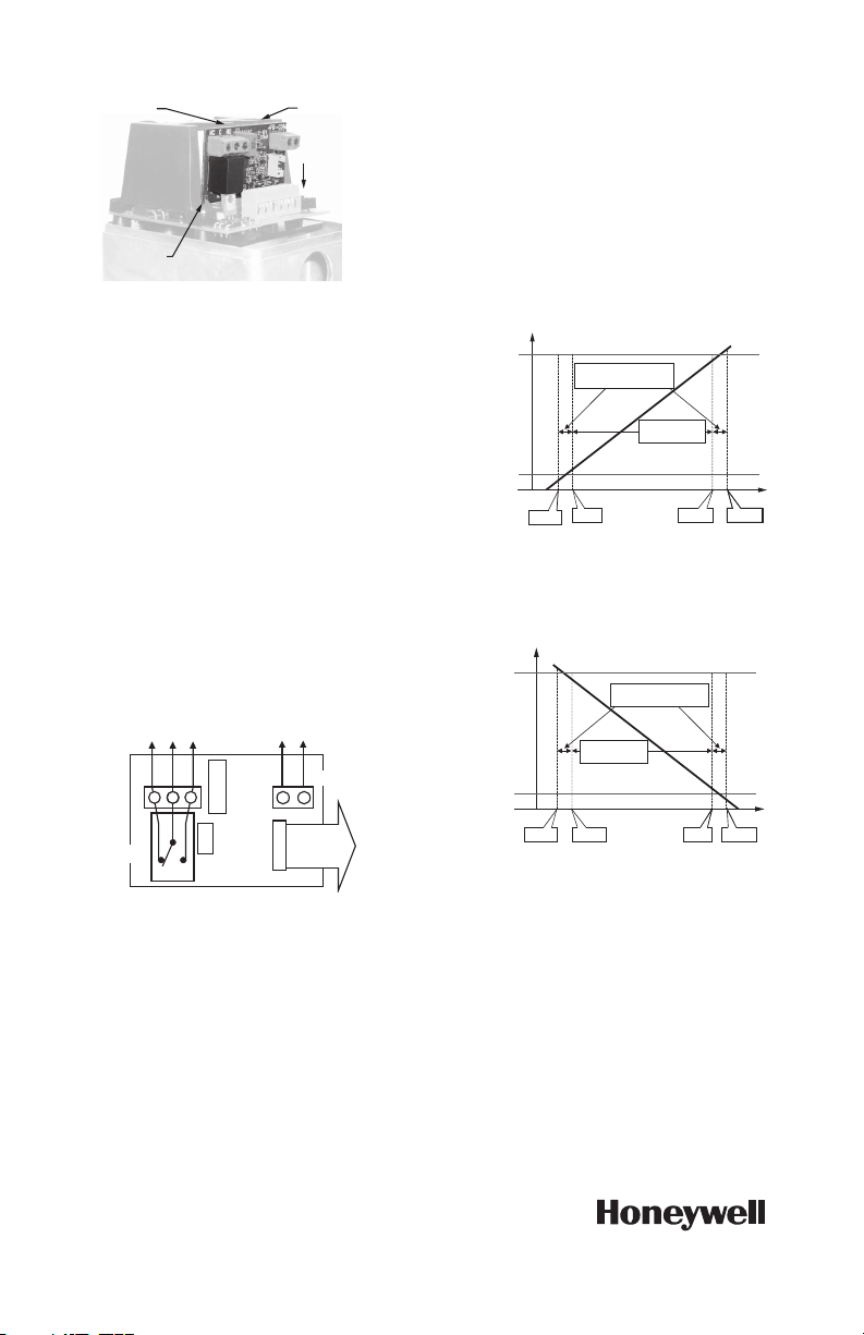
Position feedback voltage mirrors the control signal. For
ML6984 and direct acting ML7984 operation, see Fig. 3.
For reverse acting ML7984, see Fig. 4.
STROKE
UPPER
SEAT
LOWER
SEAT
Fig. 3. Feedback voltage response for ML6984 and
UPPER
SEAT
LOWER
SEAT
FIRST AND LAST STEPS
ARE @ 0.75V PER STEP
FEEDBACK VOLTAGE
2.5V 9.5V 10.25V
1.75V
direct acting ML7984.
STROKE
FIRST AND LAST STEPS
ARE @ 0.75V PER STEP
28 STEPS @
0.25V PER STEP
FEEDBACK VOLTAGE
2.5V
1.75V
28 STEPS @
0.25V PER STEP
9.5V
10.25V
M32267
M32266
Fig. 2. Wiring and operation of auxiliary board
Automation and Control Solutions
Honeywell International Inc.
1985 Douglas Drive North
Golden Valley, MN 55422
Honeywell Limited-Honeywell Limitée
35 Dynamic Drive
Toronto, Ontario M1V 4Z9
customer.honeywell.com
272630D.
CONNECT TO MAIN
BOARD FOR POSITION
FEEDBACK.
M32265
Fig. 4. Feedback voltage response for reverse acting
ML7984.
Auxiliary Switch Setup
1. Drive actuator to desired position.
2. Adjust trimmer potentiometer ("trim pot") until relay
is energized. (On-board LED will light).
® U.S. Registered Trademark
© 2010 Honeywell International In c.
95C-10941—02 T.D. Rev. 08-10
Printed in U.S.A.
 Loading...