

Page 1

™
Hyperion 1300g
General Purpose Handheld Linear Scanner
User’s Guide
Page 2

Disclaimer
Honeywell International Inc. (“HII”) reserves the right to make changes in specifications and other information contained in this document without prior notice,
and the reader should in all cases consult HII to determine whether any such
changes have been made. The information in this publication does not represent a commitment on the part of HII.
HII shall not be liable for technical or editorial errors or omissions contained
herein; nor for incidental or consequential damages resulting from the furnishing, performance, or use of this material. HII disclaims all responsibility for the
selection and use of software and/or hardware to achieve intended results.
This document contains proprietary information that is protected by copyright.
All rights are reserved. No part of this document may be photocopied, reproduced, or translated into another language without the prior written consent of
HII.
Web Address:
2010-2014 Honeywell International Inc. All rights reserved.
Other product names or marks mentioned in this document may be trademarks
or registered trademarks of other companies and are the property of their
respective owners.
For patent information, refer to www.hsmpats.com.
www.honeywellaidc.com
Page 3

Table of Contents
Chapter 1 - Getting Started
About This Manual ...................................................... 1-1
Unpacking the Scanner............................................... 1-1
Connecting with USB .................................................. 1-1
Connecting with Keyboard Wedge.............................. 1-2
Connecting with RS-232 Serial Port............................ 1-3
Connecting with RS485............................................... 1-3
Reading Techniques ................................................... 1-4
Menu Bar Code Security Settings ............................... 1-5
Chapter 2 - Programming the Interface
Introduction ................................................................. 2-1
Programming the Interface - Plug and Play ................ 2-1
Keyboard Wedge................................................... 2-1
Laptop Direct Connect........................................... 2-1
RS232 Serial Port.................................................. 2-2
RS485 ................................................................... 2-2
OPOS Mode .......................................................... 2-3
USB IBM SurePos................................................. 2-4
USB PC or Macintosh Keyboard ........................... 2-5
USB HID POS ....................................................... 2-5
USB Serial Commands ............................................... 2-5
USB Serial Emulation............................................ 2-5
CTS/RTS Emulation .............................................. 2-6
ACK/NAK Mode..................................................... 2-6
Honeywell Bioptic Aux Port Configuration................... 2-6
Datalogic™ Magellan
Wincor Mode A............................................................ 2-7
Keyboard Country Layout ........................................... 2-8
Keyboard Mode Options ........................................... 2-18
ALT Mode............................................................ 2-18
Keyboard Style .................................................... 2-18
Keyboard Modifiers ............................................. 2-19
®
Bioptic Aux Port Configuration2-7
i
Page 4

RS232 Modifiers ........................................................ 2-22
RS-232 Baud Rate............................................... 2-22
RS-232 Word Length: Data Bits, Stop Bits, and Parity
2-23
RS-232 Handshaking.................................................2-24
RS232 Timeout....................................................2-27
XON/XOFF ..........................................................2-27
ACK/NAK .............................................................2-27
Scanner to Bioptic Communication............................2-28
Scanner-Bioptic Packet Mode .............................2-28
Chapter 3 - Input/Output Settings
Good Read Indicators..................................................3-1
Beeper – Good Read............................................. 3-1
Beeper Volume – Good Read................................ 3-1
Beeper Pitch – Good Read.................................... 3-2
Beeper Duration – Good Read ..............................3-2
Beeper Pitch – Error ..............................................3-3
LED – Good Read .................................................3-3
Number of Beeps – Good Read ............................3-3
Good Read Delay ........................................................ 3-4
User-Specified Good Read Delay.......................... 3-4
Trigger Modes..............................................................3-5
Manual/Serial Trigger ............................................3-5
Automatic Trigger ..................................................3-5
Presentation Mode................................................. 3-6
Continuous Illumination Mode (Manual Trigger only) .
3-6
Hands Free Time-Out ..................................................3-6
Reread Delay...............................................................3-7
User-Specified Reread Delay ................................3-8
Centering ..................................................................... 3-8
ii
Page 5

Output Sequence Overview ...................................... 3-10
To Add an Output Sequence............................... 3-10
Other Programming Selections ........................... 3-10
Output Sequence Editor ...................................... 3-11
Output Sequence Editor ...................................... 3-13
Require Output Sequence................................... 3-13
Multiple Symbols ....................................................... 3-13
No Read .................................................................... 3-14
Video Reverse........................................................... 3-15
Chapter 4 - Data Editing
Prefix/Suffix Overview ................................................. 4-1
To Add a Prefix or Suffix ....................................... 4-2
To Clear One or All Prefixes or Suffixes................ 4-2
To Add a Carriage Return Suffix to All Symbologies4-
3
Prefix Selections.................................................... 4-3
Suffix Selections.................................................... 4-4
Function Code Transmit ........................................ 4-6
Intercharacter, Interfunction, and Intermessage Delays 4-
6
Intercharacter Delay .............................................. 4-7
User Specified Intercharacter Delay...................... 4-7
Interfunction Delay ................................................ 4-8
Intermessage Delay .............................................. 4-8
Chapter 5 - Data Formatting
Data Format Editor Introduction .................................. 5-1
To Add a Data Format........................................... 5-1
Other Programming Selections ............................. 5-2
Interface / Terminal ID Table....................................... 5-4
iii
Page 6

Data Format Editor Commands ...................................5-4
Send Commands ...................................................5-4
Move Commands................................................... 5-7
Search Commands ................................................5-8
Miscellaneous Commands................................... 5-10
Data Format Editor ..............................................5-14
Data Formatter..................................................... 5-14
Chapter 6 - Symbologies
Introduction.................................................................. 6-1
iv
Page 7

All Symbologies........................................................... 6-2
Codabar Start/Stop Characters ............................ 6-3
Codabar Check Character..................................... 6-4
Codabar Concatenation ........................................ 6-5
Codabar Message Length ..................................... 6-6
Code 39 Start/Stop Characters............................. 6-7
Code 39 Check Character..................................... 6-7
Code 39 Message Length ..................................... 6-8
Code 39 Append ................................................... 6-8
Full ASCII ............................................................ 6-10
Code 39 Code Page............................................ 6-10
Check Digit .......................................................... 6-11
Interleaved 2 of 5 Message Length..................... 6-12
Code 93 Message Length ................................... 6-13
Code 93 Code Page............................................ 6-13
Straight 2 of 5 Industrial Message Length........... 6-15
Straight 2 of 5 IATA Message Length ................. 6-16
Matrix 2 of 5 Message Length ............................. 6-17
Check Digits Required......................................... 6-18
Code 11 Message Length ................................... 6-19
ISBT 128 Concatenation ..................................... 6-19
Code 128 Message Length ................................. 6-20
Code 128 Code Page.......................................... 6-20
Code 128 Function Code Transmit ..................... 6-21
Telepen Output.................................................... 6-22
Telepen Message Length.................................... 6-23
UPC A Check Digit .............................................. 6-24
UPC A Number System....................................... 6-25
UPC A Addenda .................................................. 6-25
UPC A Addenda Required .................................. 6-26
UPC A Addenda Separator ................................. 6-26
UPC E0 and UPC E1 .......................................... 6-28
UPC E0 and UPC E1 Expand ............................. 6-29
UPC E0 and UPC E1 Addenda Required ........... 6-29
UPC E0 and UPC E1 Addenda Separator .......... 6-30
UPC E0 Check Digit ............................................ 6-30
UPC E0 Number System..................................... 6-31
v
Page 8

UPC E0 Addenda ................................................6-31
EAN/JAN 13 Check Digit .....................................6-32
EAN/JAN 13 Addenda .........................................6-33
EAN/JAN 13 Addenda Required.......................... 6-33
EAN/JAN 13 Addenda Separator ........................6-34
ISBN Translate ....................................................6-34
EAN/JAN 8 Check Digit .......................................6-35
EAN/JAN 8 Addenda ...........................................6-36
EAN/JAN 8 Addenda Required............................ 6-36
EAN/JAN 8 Addenda Separator ..........................6-37
MSI Check Character ..........................................6-37
MSI Message Length...........................................6-38
Plessey Message Length..................................... 6-39
GS1 DataBar Expanded Message Length........... 6-41
Korea Post Message Length ...............................6-43
Codablock F Message Length .............................6-44
Code 49 Message Length.................................... 6-45
Chapter 7 - Interface Keys
Keyboard Function Relationships ................................7-1
Supported Interface Keys ............................................ 7-2
Chapter 8 - Utilities
To Add a Test Code I.D. Prefix to All Symbologies ..... 8-1
Show Software Revision..............................................8-1
Show Data Format.......................................................8-1
Resetting the Standard Product Defaults ....................8-3
Chapter 9 - Serial Programming Commands
Conventions.................................................................9-1
Menu Command Syntax .............................................. 9-1
Query Commands.................................................. 9-2
Concatenation of Multiple Commands................... 9-2
Responses............................................................. 9-2
Examples of Query Commands............................. 9-3
vi
Page 9

Trigger Commands ..................................................... 9-4
Resetting the Standard Product Defaults.................... 9-4
Menu Commands........................................................ 9-5
Chapter 10 - Product Specifications
Hyperion 1300g Product Specifications .................... 10-1
Standard Connector Pinouts ..................................... 10-2
Chapter 11 - Maintenance
Repairs...................................................................... 11-1
Maintenance.............................................................. 11-1
Cleaning the Device ............................................ 11-1
Inspecting Cords and Connectors....................... 11-1
Replacing the Interface Cable ............................. 11-2
Troubleshooting ........................................................ 11-2
Chapter 12 - Customer Support
Limited Warranty ....................................................... 12-1
Symbology Charts....................................................... A-1
Linear Symbologies............................................... A-1
Postal Symbologies............................................... A-3
ASCII Conversion Chart (Code Page 1252) ...............A-3
Lower ASCII Reference Table ....................................A-5
ISO 2022/ISO 646 Character Replacements .............. A-9
vii
Page 10

viii
Page 11

1
Getting Started
About This Manual
This User’s Guide provides installation and programming instructions for the
Hyperion 1300g. Product specifications, dimensions, warranty, and customer
support information are also included.
Honeywell bar code scanners are factory programmed for the most common
terminal and communications settings. If you need to change these settings,
programming is accomplished by scanning the bar codes in this guide.
An asterisk (*) next to an option indicates the default setting.
Unpacking the Scanner
After you open the shipping carton containing the product, take the following
steps:
• Check for damage during shipment. Report damage immediately to the
carrier who delivered the carton.
• Make sure the items in the carton match your order.
• Save the shipping container for later storage or shipping.
Connecting with USB
A scanner can be connected to the USB port of a computer. The scanner emulates the keyboard.
1. Connect the appropriate interface cable to the scanner first, then to the com-
puter.
2. The scanner beeps.
1 - 1
Page 12
3. Verify the scanner operation by scanning a bar code from the Sample
only if
power
supply is
included
Symbols in the back of this manual.
For additional USB programming and technical information, refer to the Honeywell “USB Application Note,” available at www.honeywellaidc.com.
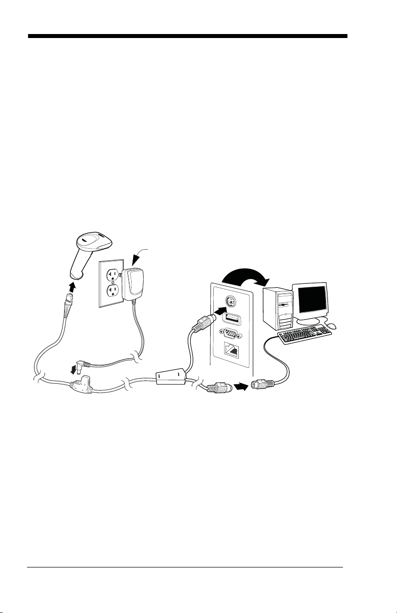
Connecting with Keyboard Wedge
A scanner can be connected between the keyboard and PC as a “keyboard
wedge,” where the scanner provides data output that is similar to keyboard
entries. The following is an example of a keyboard wedge connection:
1. Turn off power and disconnect the keyboard cables from the back of the terminal/computer.
2. Connect the appropriate interface cable to the scanner and to the terminal/
computer.
3. Turn the terminal/computer power back on. The scanner beeps.
4. Verify the scanner operation by scanning a bar code from the Sample
Symbols in the back of this manual. The scanner beeps once.
The unit defaults to an IBM PC AT and compatibles keyboard wedge interface
with a USA keyboard. A carriage return (CR) suffix is added to bar code data.
1 - 2
Page 13

Connecting with RS-232 Serial Port
only if
power
supply is
included
1. Turn off power to the terminal/computer.
2. Connect the appropriate interface cable to the scanner.
3. Plug the serial connector into the serial port on your computer. Tighten the
two screws to secure the connector to the port.
4. Once the scanner has been completely connected, power up the computer.
5. This interface programs 38,400 baud, 8 data bits, no parity, and 1 stop bit.
Connecting with RS485
A scanner can be connected for an IBM POS terminal interface.
1 - 3
Page 14
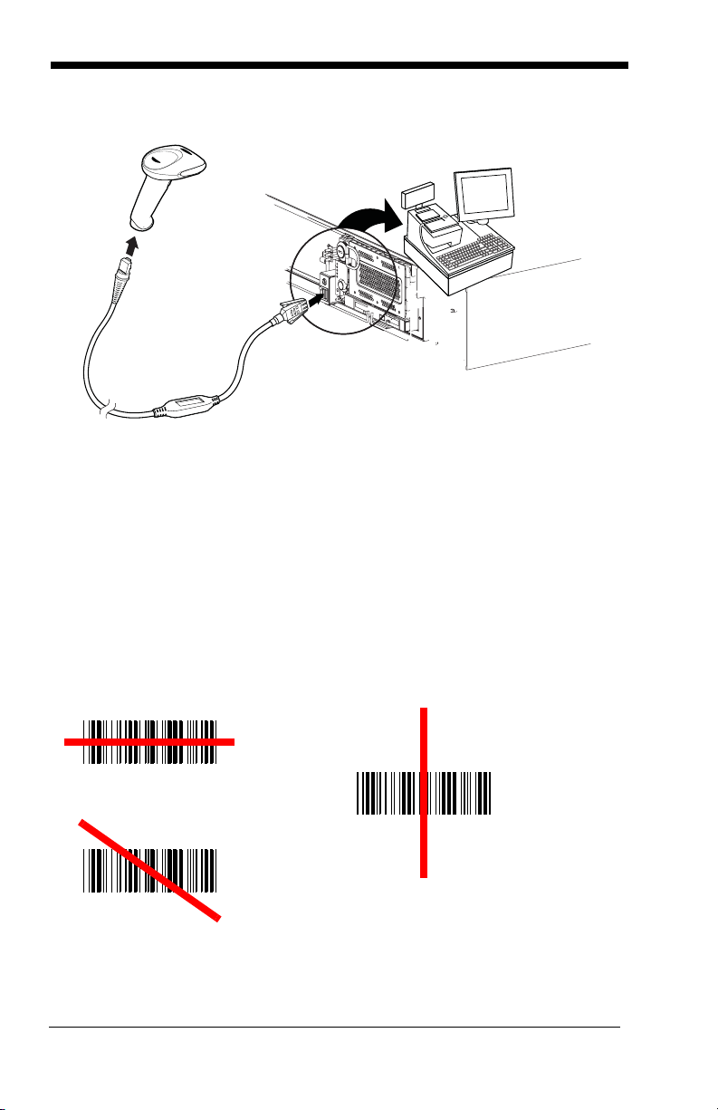
1. Connect the appropriate interface cable to the device, then to the computer.
Good Technique
Bad Technique
Bad Technique
2. Turn the terminal/computer power back on. The scanner beeps.
3. Verify the scanner operation by scanning a bar code from the Sample
Symbols in the back of this manual. The scanner beeps once.
4. For further RS485 settings, refer to RS485 on page 2-2.
Reading Techniques
The scanner has a bright red aiming beam that corresponds to its horizontal
field of view. The aiming beam should be centered horizontally over the bar
code; it will not read if the aiming beam is in any other direction.
1 - 4
Page 15

The best focus point for reading most code densities is about 5 inches (12.7 cm)
Set Custom Defaults
Activate Custom Defaults
from the unit. To read a single bar code or multiple bar codes (on a page or on
an object), hold the scanner at an appropriate distance from the target, pull the
trigger, and center the aiming beam on the bar code.
Menu Bar Code Security Settings
Honeywell scanners are programmed by scanning menu bar codes or by sending serial commands to the scanner. If you want to restrict the ability to scan
menu codes, you can use the Menu Bar Code Security settings. Contact Technical Support (seeCustomer Support on page 12-1) for further information.
Setting Custom Defaults
You have the ability to create a set of menu commands as your own, custom
defaults. To do so, scan the Set Custom Defaults bar code below before each
menu command or sequence you want saved. If your command requires scanning numeric codes from the back cover, then a Save code, that entire
sequence will be saved to your custom defaults. Scan the Set Custom
Defaults code again before the next command you want saved to your custom
defaults.
You may have a series of custom settings and want to correct a single setting.
To do so, just scan the new setting to overwrite the old one. For example, if you
had previously saved the setting for Beeper Volume at Low to your custom
defaults, and decide you want the beeper volume set to High, just scan the Set
Custom Defaults bar code, then scan the Beeper Volume High menu code.
The rest of the custom defaults will remain, but the beeper volume setting will be
updated.
Resetting the Custom Defaults
If you want the custom default settings restored to your scanner, scan the Activate Custom Defaults bar code below. This resets the scanner to the custom
default settings. If there are no custom defaults, it will reset the scanner to the
factory default settings. Any settings that have not been specified through the
custom defaults will be defaulted to the factory default settings.
1 - 5
Page 16

The Serial Programming Commands starting on page 9-1 lists the factory
default settings for each of the commands (indicated by an asterisk (*) on the
programming pages).
1 - 6
Page 17

2
IBM PC AT and Compatibles with CR Suffix
Laptop Direct Connect
with CR suffix
Programming the Interface
Introduction
This chapter describes how to program your system for the desired interface.
Programming the Interface - Plug and Play
Plug and Play bar codes provide instant scanner set up for commonly used
interfaces.
Note: After you scan one of the codes, power cycle the host terminal to have
the interface in effect.
Keyboard Wedge
If you want your system programmed for an IBM PC AT and compatibles keyboard wedge interface with a USA keyboard, scan the bar code below. Keyboard wedge is the default interface.
Note: The following bar code also programs a carriage return (CR) suffix.
Laptop Direct Connect
For most laptops, scanning the Laptop Direct Connect bar code allows operation of the scanner in parallel with the integral keyboard. The following Laptop
Direct Connect bar code selects terminal ID 03, programs a carriage return
(CR) suffix and turns on Emulate External Keyboard (page 2-19).
2 - 1
Page 18
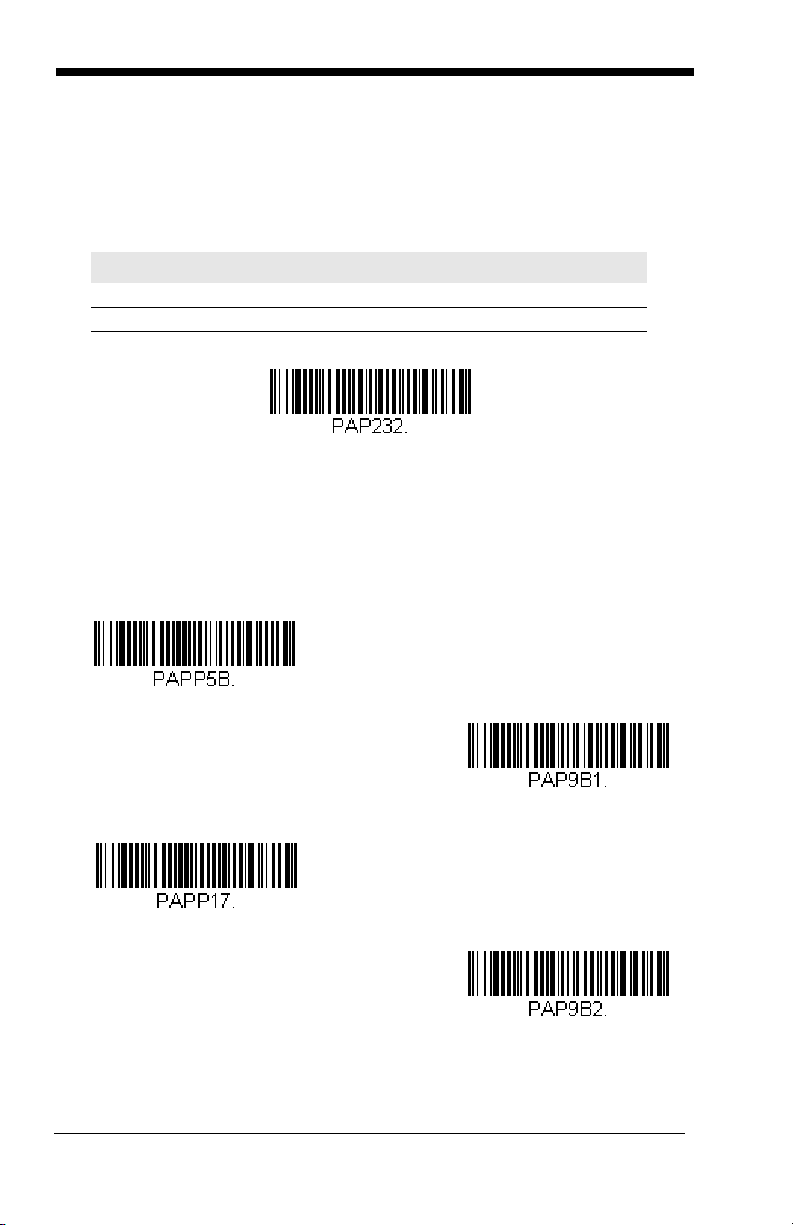
RS232 Serial Port
RS232 Interface
IBM Port 5B Interface
IBM Port 9B
HHBCR-1 Interface
IBM Port 17 Interface
IBM Port 9B
HHBCR-2 Interface
The RS232 Interface bar code is used when connecting to the serial port of a
PC or terminal. The following RS232 Interface bar code also programs a carriage return (CR) and a line feed (LF) suffix, baud rate, and data format as indi-
cated below.
Option Setting
Baud Rate 38,400 bps
Data Format 8 data bits, no parity bit, 1 stop bit
RS485
Scan one of the following “Plug and Play” codes to program the scanner for an
IBM POS terminal interface.
Note: After scanning one of these codes, you must power cycle the cash
register.
2 - 2
Page 19

Each bar code above also programs the following suffixes for each symbology:
Symbology Suffix Symbology Suffix
EAN 8 0C Code 39 00 0A 0B
EAN 13 16 Interleaved 2 of 5 00 0D 0B
UPC A 0D Code 128 * 00 0A 0B
UPC E 0A Code 128 ** 00 18 0B
* Suffixes programmed for Code 128 with IBM 4683 Port 5B, IBM 4683 Port 9B
HHBCR-1, and IBM 4683 Port 17 Interfaces
**Suffixes programmed for Code 128 with IBM 4683 Port 9 HHBCR-2 Interface
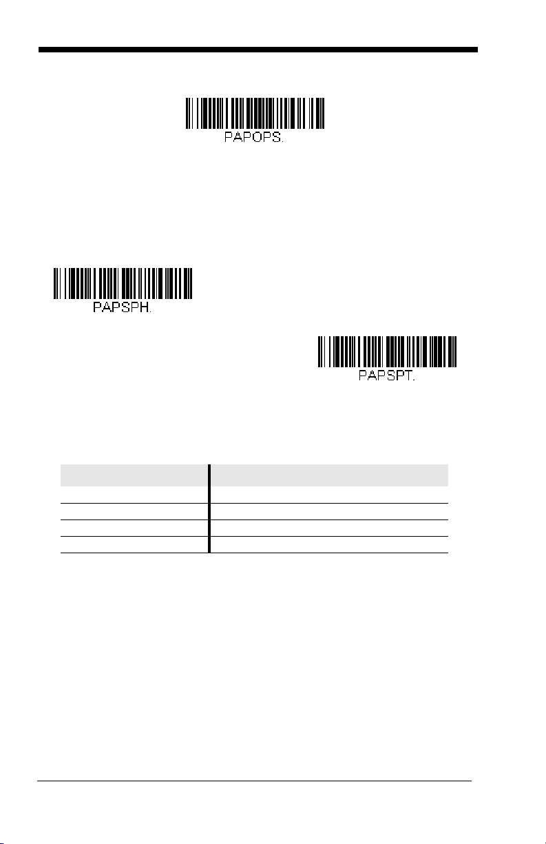
OPOS Mode
The following bar code configures your scanner for OPOS (OLE for Retail Point
of Sale) by modifying the following OPOS-related settings:
Option Setting
Interface RS232
Baud Rate 38400
RS232
Handshaking
Data Bits, Stop
Bits, and Parity
Prefix/Suffix
Intercharacter
Delay
Symbologies Enable UPC-A with check digit and number system
Flow Control, No Timeout
XON/XOFF Off
ACK/NAK Off
8 Data, 1 Stop, Parity None
Clear All Prefixes and Suffixes
Add Code ID and AIM ID Prefix
Add CR Suffix
Off
Enable UPC-E0 with check digit
Enable EAN/JAN-8 with check digit
Enable EAN/JAN-13 with check digit
Enable Code 128
Enable Code 39
Enable OPOS with automatic disable off
2 - 3
Page 20
USB IBM SurePos
OPOS Mode
USB IBM SurePos
(USB Handheld Scanner)
Interface
USB IBM SurePos
(USB Tabletop Scanner)
Interface
Scan the following “Plug and Play” codes to program the scanner for an IBM
SurePos (USB handheld scanner) interface.
Note: After scanning the code below, you must power cycle the cash register.
The bar code above also programs the following suffixes for each symbology:
Symbology Suffix Symbology Suffix
EAN 8 0C Code 39 00 0A 0B
EAN 13 16 Interleaved 2 of 5 00 0D 0B
UPC A 0D Code 128 00 18 0B
UPC E 0A Code 39 00 0A 0B
2 - 4
Page 21

USB PC or Macintosh Keyboard
U
S
B
K
e
y
b
o
a
r
d
(
P
C
)
USB Keyboard (Mac)
USB HID POS Bar Code
Scanner
USB Serial Emulation
Scan one of the following codes to program the scanner for USB PC Keyboard
or USB Macintosh Keyboard. Scanning these codes also adds a CR and LF.
USB HID POS
Scan the following code to program the scanner for USB HID POS bar code
scanners.
USB Serial Commands
USB Serial Emulation
Scan the following code to program the scanner to emulate a regular RS232based COM Port. If you are using a Microsoft® Windows® PC, you will need to
download a driver from the Honeywell website (www.honeywellaidc.com). The
driver will use the next available COM Port number. Apple® Macintosh computers recognize the scanner as a USB CDC class device and automatically uses a
class driver.
Scanning this code also adds a CR and LF.
Note: No extra configuration (e.g., baud rate) is necessary.
2 - 5
Page 22
CTS/RTS Emulation
CTS/RTS Emulation On
* CTS/RTS Emulation Off
ACK/NAK Mode On
* ACK/NAK Mode Off
Honeywell Bioptic Settings
ACK/NAK Mode
Honeywell Bioptic Aux Port Configuration
Scan the following Plug and Play code to program the scanner for a Honeywell
bioptic scanner auxiliary port configuration. This bar code sets the baud rate to
38400 bps and the data format to 8 data bits, no parity, 1 stop bit. Character
RTS/CTS with timeout and 232 ACK/NAK are also enabled.
Note: If you are having unexpected results with this programming code, scan
the Resetting the Custom Defaults bar code on page 1-5 first, then scan
the programming code above.
2 - 6
Page 23

Datalogic™ Magellan®Bioptic
Datalogic Magellan Bioptic Settings
Wincor Mode A
Aux Port Configuration
Scan the following Plug and Play code to program the scanner for a Datalogic
Magellan bioptic scanner auxiliary port configuration. This bar code sets the
baud rate to 9600 bps and the data format to 8 data bits, no parity, 1 stop bit.
Note: If you are having unexpected results with this programming code, scan
the Resetting the Custom Defaults bar code on page 1-5 first, then scan
the programming code above.
Wincor Mode A
Scan the following Plug and Play code to program the scanner for Wincor Mode
A mode. This bar code sets the baud rate to 9600 bps and the data format to 8
data bits, odd parity, 1 stop bit.
Note: If you are having unexpected results with this programming code, scan
the Resetting the Custom Defaults bar code on page 1-5 first, then scan
the programming code above.
2 - 7
Page 24
Keyboard Country Layout
* United States
Albania
Arabic
Azeri (Cyrillic)
Azeri (Latin)
Belarus
Belgium
Bosnia
Scan the appropriate country code below to program the keyboard layout for
your country or language. As a general rule, the following characters are supported, but need special care for countries other than the United States:
@ | $ # { } [ ] = / ‘ \ < > ~
2 - 8
Page 25
Brazil
Brazil (MS)
Bulgaria (Cyrillic)
Bulgaria (Latin)
Canada (French legacy)
Canada (French)
Canada (Multilingual)
China
Croatia
2 - 9
Page 26
2 - 10
Czech
Czech (Programmers)
Czech (QWERTY)
Czech (QWERTZ)
Denmark
Dutch (Netherlands)
Estonia
Faroese
Finland
Page 27
France
Gaelic
Germany
Greek
Greek (220 Latin)
Greek (220)
Greek (319 Latin)
Greek (319)
Greek (Latin)
2 - 11
Page 28
2 - 12
Greek (MS)
Greek (Polytonic)
Hebrew
Hungarian (101 key)
Hungary
Iceland
Ireland
Italian (142)
Italy
Page 29

Japan ASCII
Kazakh
Korea
Kyrgyz (Cyrillic)
Latin America
Latvia
Latvia (QWERTY)
Lithuania
Lithuania (IBM)
2 - 13
Page 30
2 - 14
Macedonia
Malta
Mongolian (Cyrillic)
Norway
Poland
Polish (214)
Polish (Programmers)
Portugal
Romania
Page 31

[
Russia
Russian (MS)
Russian (Typewriter)
SCS
Serbia (Cyrillic)
Serbia (Latin)
Slovakia
Slovakia (QWERTY)
Slovakia (QWERTZ)
2 - 15
Page 32

2 - 16
Slovenia
Spain
Spanish variation
Sweden
Switzerland (French)
Switzerland (German)
Tatar
Thailand
Turkey F
Page 33

Turkey Q
Ukrainian
United Kingdom
United Stated (Dvorak right)
United States (Dvorak left)
United States (Dvorak)
United States (International)
Uzbek (Cyrillic)
Vietnam
2 - 17
Page 34

Keyboard Mode Options
* Off
4 Characters
* Regular
Caps Lock
ALT Mode
If your bar code contains special characters from the extended ASCII chart for
example, an e with an accent grave (è), you will use ALT Mode. (See Extended
ASCII Characters on page A-6.)
Note: Scan the ALT mode bar code after scanning the appropriate Keyboard
Country code.
If your keystrokes require the ALT key and 4 characters, scan the 4 Characters
bar code. The data is then output with the special character(s). Default = Off.
Keyboard Style
This programs keyboard styles, such as Caps Lock and Shift Lock. Default =
Regular.
Regular is used when you normally have the Caps Lock key off.
Caps Lock is used when you normally have the Caps Lock key on.
2 - 18
Page 35

Shift Lock is used when you normally have the Shift Lock key on (not common
Shift Lock
Automatic Caps Lock
Autocaps via NumLock
Emulate External Keyboard
to U.S. keyboards).
Automatic Caps Lock is used if you change the Caps Lock key on and off.
The software tracks and reflects if you have Caps Lock on or off (AT and PS/2
only). This selection can only be used with systems that have an LED, which
notes the Caps Lock status.
Autocaps via NumLock bar code should be scanned in countries (e.g., Germany, France) where the Caps Lock key cannot be used to toggle Caps Lock.
The NumLock option works similarly to the regular Auotcaps, but uses the NumLock key to retrieve the current state of the Caps Lock.
Emulate External Keyboard should be scanned if you do not have an external
keyboard (IBM AT or equivalent).
Note: After scanning the Emulate External Keyboard bar code, you must power
cycle your computer.
Keyboard Modifiers
This modifies special keyboard features, such as CTRL+ ASCII codes.
Control + X (Control + ASCII) Mode On: The scanner sends key combinations for ASCII control characters for values 00-1F. Windows is the preferred
mode. All keyboard country codes are supported. DOS mode is a legacy
2 - 19
Page 36

mode, and it does not support all keyboard country codes. New users should
Windows Mode Control + X
Mode On
* Control + X Mode Off
DOS Mode Control + X Mode
On
Windows Mode Prefix/Suffix Off
use the Windows mode. Refer to Keyboard Function Relationships, page 7-1
for CTRL+ X Values.
Windows Mode Prefix/Suffix Off: The scanner sends key combinations for
ASCII control characters for values 00-1F (refer to ASCII Conversion Chart
(Code Page 1252) on page A-3 for non-reprintable characters), but it does not
translate any prefix or suffix information.
Default = Control + ASCII Off
2 - 20
Page 37

Numeric Keypad Mode: Sends numeric characters as if entered from a
Numeric Keypad Mode On
* Numeric Keypad Mode Off
Automatic Direct
Connect Mode On
* Automatic Direct Connect
Mode Off
numeric keypad. Default = Off
Automatic Direct Connect Mode: This selection can be used if you have an
IBM AT style terminal and the system is dropping characters. Default = Off
2 - 21
Page 38

RS232 Modifiers
300
600
1200
2400
4800
9600
19200
RS-232 Baud Rate
Baud Rate sends the data from the scanner to the terminal at the specified rate.
The host terminal must be set for the same baud rate as the scanner.
Default = 38,400.
2 - 22
Page 39

RS-232 Word Length: Data Bits, Stop Bits, and Parity
* 38400
57,600
115,200
7 Data, 1 Stop, Parity None
(see note above)
7 Data, 1 Stop, Parity Even
Data Bits sets the word length at 7 or 8 bits of data per character. If an application requires only ASCII Hex characters 0 through 7F decimal (text, digits, and
punctuation), select 7 data bits. For applications which require use of the full
ASCII set, select 8 data bits per character. Default = 8.
Stop Bits sets the stop bits at 1 or 2. Default = 1.
Parity provides a means of checking character bit patterns for validity.
Default = None.
Note: When using 7 Data, 1 Stop, Parity None, the host must insert at least a 1
bit delay between characters. If this is not done, a different RS232 Word
Length format must be used.
2 - 23
Page 40

RS-232 Handshaking
7 Data, 1 Stop, Parity Odd
7 Data, 2 Stop Parity None
7 Data, 2 Stop, Parity Even
7 Data, 2 Stop, Parity Odd
* 8 Data, 1 Stop, Parity None
8 Data, 1 Stop, Parity Even
8 Data, 1 Stop, Parity Odd
RS232 Handshaking allows control of data transmission from the scanner using
software commands from the host device.
RTS/CTS Off: RTS/CTS is turned off so no data flow control is used, but RTS
is still active.
2 - 24
Page 41

RTS/CTS Off, RTS Inactive: RTS/CTS is turned off so no data flow control is
* RTS/CTS Off
RTS/CTS Off, RTS Inactive
Flow Control, No Timeout
used and RTS is inactive.
Flow Control, No Timeout: The scanner asserts RTS when it has data to
send, and will wait indefinitely for CTS to be asserted by the host.
Character-Based Flow Control, No Timeout: The scanner asserts RTS when
it has a character to send, and will wait indefinitely for CTS to be asserted by the
host
Two-Direction Flow Control: The scanner asserts RTS when it is OK for the
host to transmit. The host asserts CTS when it is OK for the device to transmit.
Flow Control with Timeout: The scanner asserts RTS when it has data to
send and waits for a delay (see RS232 Timeout on page 2-27) for CTS to be
asserted by the host. If the delay time expires and CTS is not asserted, the
device transmit buffer is cleared and scanning may resume.
Character-Based Flow Control with Timeout: The scanner asserts RTS
when it has a character to send and waits for a delay (see RS232 Timeout on
page 2-27) for CTS to be asserted by the host. If the delay time expires and
CTS is not asserted, the device transmit buffer is cleared and scanning may
resume.
CTS-Based Flow Control, No Timeout: When the host asserts CTS, scanning is enabled. When CTS is not asserted, scanning is disabled.
RTS On: RTS only is on during transmission. CTS is ignored.
Default = RTS/CTS Off.
2 - 25
Page 42

2 - 26
Character-Based Flow
Control, No Timeout
Two-Direction Flow
Control
Flow Control with
Timeout
Character-Based Flow
Control with Timeout
CTS-Based Flow Control,
No Timeout
RTS On
No RTS if CTS is On
Page 43

RS232 Timeout
RS232 Timeout
* XON/OFF Off
XON/XOFF On
When using Flow Control with Timeout, you must program the length of the
delay you want to wait for CTS from the host. Set the length (in milliseconds) for
a timeout by scanning the bar code below, then setting the timeout (from 165535 milliseconds) by scanning digits from the inside back cover, then scanning Save. Default = 1000.
XON/XOFF
Standard ASCII control characters can be used to tell the scanner to start sending data (XON/XOFF On) or to stop sending data (XON/XOFF Off). When the
host sends the XOFF character (DC3, hex 13) to the scanner, data transmission
stops. To resume transmission, the host sends the XON character (DC1, hex
11). Data transmission continues where it left off when XOFF was sent. Default
= XON/XOFF Off.
ACK/NAK
After transmitting data, the scanner waits for an ACK character (hex 06) or a
NAK character (hex 15) response from the host. If ACK is received, the communications cycle is completed and the scanner looks for more bar codes. If NAK
is received, the last set of bar code data is retransmitted and the scanner waits
2 - 27
Page 44

for ACK/NAK again. Turn on the ACK/NAK protocol by scanning the ACK/NAK
ACK/NAK On
* ACK/NAK Off
* Packet Mode Off
Packet Mode On
On bar code below. To turn off the protocol, scan ACK/NAK Off. Default =
ACK/NAK Off.
Scanner to Bioptic Communication
The following settings are used to set up communication between Honeywell
scanners and bioptic scanners.
Note: The scanner’s baud rate must be set to 38400 and the RS232 timeout
must be set to 3000 in order to communicate with a bioptic scanner. See
"RS232 Modifiers" on page 2-22, and RS232 Timeout on page 2-27 for
further information.
Scanner-Bioptic Packet Mode
Packet Mode On must be scanned to set the scanner’s format so it is compatible with a bioptic scanner. Default = Packet Mode Off.
2 - 28
Page 45

3
* On
Off
*High
Medium
Off
Low
Input/Output Settings
Good Read Indicators
Beeper – Good Read
The beeper may be programmed On or Off in response to a good read. Turning
this option off, only turns off the beeper response to a good read indication. All
error and menu beeps are still audible. Default = On.
Beeper Volume – Good Read
The beeper volume codes modify the volume of the beep the scanner emits on
a good read. Default = High.
3 - 1
Page 46

Beeper Pitch – Good Read
Low (1600 Hz)
* Medium (2750 Hz)
High (4200 Hz)
* Normal Beep
Short Beep
The beeper pitch codes modify the pitch (frequency) of the beep the scanner
emits on a good read. Default = Medium
Beeper Duration – Good Read
The beeper duration codes modify the length of the beep the scanner emits on
a good read. Default = Normal.
3 - 2
Page 47

Beeper Pitch – Error
* Razz (100 Hz)
* Medium (2000 Hz)
High (4200 Hz)
* On
Off
The beeper pitch codes modify the pitch (frequency) of the sound the scanner
emits when there is a bad read or error. Default = 100 Hz.
LED – Good Read
The LED indicator can be programmed On or Off in response to a good read.
Default = On.
Number of Beeps – Good Read
The number of beeps of a good read can be programmed from 1 - 9. The same
number of beeps will be applied to the beeper and LED in response to a good
read. For example, if you program this option to have five beeps, there will be
five beeps and five LED flashes in response to a good read. The beeps and
3 - 3
Page 48

LED flashes are in sync with one another. To change the number of beeps,
Number of Pulses
* No Delay
Short Delay (500 ms)
Medium Delay (1000 ms)
Long Delay (1500 ms)
User-Specified Good Read Delay
scan the bar code below and then scan a digit (1-9) bar code and the Save bar
code on the inside the back cover of this manual. Default = One.
Good Read Delay
This sets the minimum amount of time before the scanner can read another bar
code. Default = No Delay.
User-Specified Good Read Delay
If you want to set your own length for the good read delay, scan the bar code
below, then set the delay (from 0-30,000 milliseconds) by scanning digits from
the inside back cover, then scanning Save.
3 - 4
Page 49

Trigger Modes
* Manual/Serial Trigger
Read Time-Out
Automatic Trigger
Manual/Serial Trigger
You can activate the scanner either by pressing the trigger, or using a serial trigger command (see Trigger Commands on page 9-4). When in manual trigger
mode, the scanner scans until a bar code is read, or until the trigger is released.
When in serial mode, the scanner scans until a bar code has been read or until
the deactivate command is sent. In serial mode, the scanner can also be set to
turn itself off after a specified time has elapsed (see Read Time-Out, which follows).
Read Time-Out
Use this selection to set a time-out (in milliseconds) of the scanner’s trigger
when using serial commands to trigger the scanner. Once the scanner has
timed out, you can activate the scanner either by pressing the trigger or using a
serial trigger command. After scanning the Read Time-Out bar code, set the
time-out duration (from 0-300,000 milliseconds) by scanning digits from the
inside back cover, then scanning Save. Default = 30,000.
Automatic Trigger
The scanner scans continuously using internal LEDs to detect bar codes.
3 - 5
Page 50

Presentation Mode
Presentation Mode
Continuous Illumination
Mode On
* Continuous Illumination
Mode Off
Presentation Mode uses ambient light to detect bar codes. The LEDs are off for
ambient conditions until a change occurs in the scanner’s field of view. Then
the LEDS turn on automatically to read the code. If the light level in the room is
not high enough, Presentation Mode may not work properly.
Continuous Illumination Mode (Manual Trigger only)
If you have several bar codes that are close together, you may wish to have a
continuous aiming beam on in order to properly aim the scanner at one bar
code. Scan the Continuous Illumination On bar code to program the scanner
for this capability. Once you have the aiming beam over the correct bar code,
pull the trigger to read the code. Scan the Continuous Illumination Off bar
code to turn off this feature.
Hands Free Time-Out
The Automatic Trigger and Presentation Modes are referred to as “hands free”
modes. If the scanner’s trigger is pulled when using a hands free mode, the
scanner changes to manual trigger mode. You can set the time the scanner
should remain in manual trigger mode by setting the Hands Free Time-Out.
Once the time-out value is reached, (if there have been no further trigger pulls)
the scanner reverts to the original hands free mode.
3 - 6
Page 51

Scan the Hands Free Time-Out bar code, then scan the time-out duration
Hands Free Time-Out
Short (500 ms)
* Medium (750 ms)
Long (1000 ms)
Extra Long (2000 ms)
(from 0-300,000 milliseconds) from the inside back cover, and Save. Default =
5,000 ms.
Reread Delay
This sets the time period before the scanner can read the same bar code a second time. Setting a reread delay protects against accidental rereads of the
same bar code. Longer delays are effective in minimizing accidental rereads at
POS (point of sale). Use shorter delays in applications where repetitive bar
code scanning is required. Default = Medium.
Reread Delay only works when in automatic trigger mode or presentation mode
(see page 3-5).
3 - 7
Page 52

User-Specified Reread Delay
User-Specified Reread Delay
0% 10% 20% 30% 40 % 50% 60% 70% 80 % 90% 100%
Bar Code 1 Bar Code 2
If you want to set your own length for the reread delay, scan the bar code below,
then set the delay (from 0-30,000 milliseconds) by scanning digits from the
inside back cover, then scanning Save.
Centering
Use Centering to narrow the scanner’s field of view to make sure the scanner
reads only those bar codes intended by the user. For instance, if multiple codes
are placed closely together, centering will insure that only the desired codes are
read.
If a bar code is not touched by a predefined window, it will not be decoded or
output by the scanner. If centering is turned on by scanning Centering On, the
scanner only reads codes that pass through the centering window you specify
using the Left of Centering Window, or Right of Centering Window bar
codes.
In the example below, the red line is the full scanner field of view and the white
boxed area is the centering window. The centering window has been set to
20% left and 30% right, as shown in the legend at the bottom. Since Bar Code
1 passes through the centering window, it will be read. Bar Code 2 does not
pass through the centering window, so it will not be read.
Scan Centering On, then scan one of the following bar codes to change the left
or right of the centering window. Then scan the percent you want to shift the
centering window using digits on the inside back cover of this manual. Scan
Save. Default Centering = 40% for Left, 60% for Right.
3 - 8
Page 53

Left of Centering Window
Right of Centering Window
* Centering Off
Centering On
3 - 9
Page 54

Output Sequence Overview
Output Sequence Editor
This programming selection allows you to program the scanner to output data
(when scanning more than one symbol) in whatever order your application
requires, regardless of the order in which the bar codes are scanned. Reading
the Default Sequence symbol programs the scanner to the Universal values,
shown below. These are the defaults. Be certain you want to delete or clear all
formats before you read the Default Sequence symbol.
Note: To make Output Sequence Editor selections, you’ll need to know the
code I.D., code length, and character match(es) your application
requires. Use the Alphanumeric symbols (inside back cover) to read
these options.
Note: You must hold the trigger while reading each bar code in a sequence.
To Add an Output Sequence
1. Scan the Enter Sequence symbol (see Require Output Sequence, page 3-
13).
2. Code I.D.
On the Symbology Charts on page A-1, find the symbology to which you
want to apply the output sequence format. Locate the Hex value for that
symbology and scan the 2 digit hex value from the Programming Chart
(inside back cover).
3. Length
Specify what length (up to 9999 characters) of data output will be acceptable
for this symbology. Scan the four digit data length from the Programming
Chart. (Note: 50 characters is entered as 0050. 9999 is a universal number, indicating all lengths.) When calculating the length, you must count any
programmed prefixes, suffixes, or formatted characters as part of the length
(unless using 9999).
4. Character Match Sequences
On the ASCII Conversion Chart (Code Page 1252), page A-3, find the Hex
value that represents the character(s) you want to match. Use the Programming Chart to read the alphanumeric combination that represents the ASCII
characters. (99 is the Universal number, indicating all characters.)
5. End Output Sequence Editor
Scan F F to enter an Output Sequence for an additional symbology, or Save
to save your entries.
Other Programming Selections
•Discard
This exits without saving any Output Sequence changes.
3 - 10
Page 55

Output Sequence Editor
Enter Sequence
Default Sequence
A - Code 39
B - Code 128
C - Code 93
Output Sequence Example
In this example, you are scanning Code 93, Code 128, and Code 39 barcodes,
but you want the image scanner to output Code 39 1st, Code 128 2nd, and
Code 93 3rd, as shown below.
Note: Code 93 must be enabled to use this example.
You would set up the sequence editor with the following command line:
SEQBLK62999941FF6A999942FF69999943FF
The breakdown of the command line is shown below:
SEQBLKsequence editor start command
62 code identifier for Code 39
9999 code length that must match for Code 39, 9999 = all lengths
41 start character match for Code 39, 41h = “A”
FF termination string for first code
6A code identifier for Code 128
9999 code length that must match for Code 128, 9999 = all lengths
3 - 11
Page 56

42 start character match for Code 128, 42h = “B”
FF termination string for second code
69 code identifier for Code 93
9999 code length that must match for Code 93, 9999 = all lengths
43 start character match for Code 93, 43h = “C”
FF termination string for third code
To program the previous example using specific lengths, you would have to
count any programmed prefixes, suffixes, or formatted characters as part of the
length. If you use the example on page 3-11, but assume a <CR> suffix and
specific code lengths, you would use the following command line:
SEQBLK62001241FF6A001342FF69001243FF
The breakdown of the command line is shown below:
SEQBLK sequence editor start command
62 code identifier for Code 39
0012 A - Code 39 sample length (11) plus CR suffix (1) = 12
41 start character match for Code 39, 41h = “A”
FF termination string for first code
6A code identifier for Code 128
0013 B - Code 128 sample length (12) plus CR suffix (1) = 13
42 start character match for Code 128, 42h = “B”
FF termination string for second code
69 code identifier for Code 93
0012 C - Code 93 sample length (11) plus CR suffix (1) = 12
43 start character match for Code 93, 43h = “C”
FF termination string for third code
3 - 12
Page 57

Output Sequence Editor
Enter Sequence
Default Sequence
Required
On/Not Required
*Off
Require Output Sequence
When an output sequence is Required, all output data must conform to an
edited sequence or the image scanner will not transmit the output data to the
host device. When it’s On/Not Required, the image scanner will attempt to get
the output data to conform to an edited sequence, but if it cannot, the image
scanner transmits all output data to the host device as is.
When the output sequence is Off, the barcode data is output to the host as the
image scanner decodes it.
Note: This selection is unavailable when the Multiple Symbols Selection is
turned on.
Multiple Symbols
When this programming selection is turned On, it allows you to read multiple
symbols with a single pull of the scanner’s trigger. If you press and hold the trigger, aiming the scanner at a series of symbols, it reads unique symbols once,
3 - 13
Page 58

beeping (if turned on) for each read. The scanner attempts to find and decode
On
* Off
On
* Off
new symbols as long as the trigger is pulled. When this programming selection
is turned Off, the scanner will only read the symbol closest to the aiming beam.
No Read
With No Read turned On, the scanner sends an “NR” to the host if you pull and
release the trigger without reading a code (e.g., bad bar code). If No Read is
turned Off, the “NR” will not be sent to the host.
If you want a different notation than “NR,” for example, “Error,” or “Bad Code,”
you can edit the output message using the Data Formatter (page 5-14). The
hex code for the No Read symbol is 9C.
3 - 14
Page 59

Video Reverse
On
VIDREV0REV.
* Off
Video Reverse is used to allow the scanner to read bar codes that are inverted.
The “Off” bar code below is an example of this type of bar code.
Note: If additional menuing is required, Video Reverse must be disabled to read
the menu bar codes and then re-enabled after menuing is completed.
3 - 15
Page 60

3 - 16
Page 61

4
Data Editing
Prefix/Suffix Overview
When a bar code is scanned, additional information is sent to the host computer
along with the bar code data. This group of bar code data and additional,
user-defined data is called a “message string.” The selections in this section
are used to build the user-defined data into the message string.
Prefix and Suffix characters are data characters that can be sent before and
after scanned data. You can specify if they should be sent with all symbologies,
or only with specific symbologies. The following illustration shows the breakdown of a message string:
Prefix
alpha numeric
characters
Scanned Data
variable length1-11
Suffix
1-11
alpha numeric
characters
Points to Keep In Mind
• It is not necessary to build a message string. The selections in this chapter
are only used if you wish to alter the default settings.
Note: Plug and Play bar codes for interface selections (see Programming the
Interface - Plug and Play on page 2-1) automatically program a CR/LF
suffix.
• A prefix or suffix may be added or cleared from one symbology or all
symbologies.
• You can add any prefix or suffix from the ASCII Conversion Chart (Code Page
1252), page A-3, plus Code I.D. and AIM I.D.
• You can string together several entries for several symbologies at one time.
• Enter prefixes and suffixes in the order in which you want them to appear on
the output.
• When setting up for specific symbologies (as opposed to all symbologies), the
specific symbology ID value counts as an added prefix or suffix character.
• The maximum size of a prefix or suffix configuration is 200 characters, which
includes header information
4 - 1
Page 62

To Add a Prefix or Suffix
Step 1. Scan the Add Prefix or Add Suffix symbol (page 4-3).
Step 2. Determine the 2 digit Hex value from the Symbology Chart (included in
Appendix A) for the symbology to which you want to apply the prefix or
suffix. For example, for Code 128, Code ID is “j” and Hex ID is “6A”.
Step 3. Scan the 2 hex digits from the inside the back cover of this manual or
scan 9, 9 for all symbologies.
Step 4. Determine the hex value from the ASCII Conversion Chart (Code Page
1252), page A-3, for the prefix or suffix you wish to enter.
Step 5. Scan the 2 digit hex value from the inside the back cover of this man-
ual.
Step 6. Repeat Steps 4 and 5 for every prefix or suffix character.
Step 7. To add the Code I.D., scan 5, C, 8, 0.
To add AIM I.D., scan 5, C, 8, 1.
To add a backslash (\), scan 5, C, 5, C.
Note: To add a backslash (\) as in Step 7, you must scan 5C twice – once to
create the leading backslash and then to create the backslash itself.
Step 8. Scan Save to exit and save, or scan Discard to exit without saving.
Repeat Steps 1-6 to add a prefix or suffix for another symbology.
Example: Add a Tab Suffix to All Symbologies
Step 1. Scan Add Suffix.
Step 2. Scan 9, 9 from the Programming Chart inside the back cover of this
manual to apply this suffix to all symbologies.
Step 3. Scan 0, 9 from the Programming Chart inside the back cover of this
manual. This corresponds with the hex value for a horizontal tab,
shown in the ASCII Conversion Chart (Code Page 1252), beginning on
page A-3.
Step 4. Scan Save, or scan Discard to exit without saving.
To Clear One or All Prefixes or Suffixes
You can clear a single prefix or suffix, or clear all prefixes/suffixes for a symbology. When you Clear One Prefix (Suffix), the specific character you select is
deleted from the symbology you want. When you Clear All Prefixes (Suffixes),
all the prefixes or suffixes for a symbology are deleted.
4 - 2
Page 63

Step 1. Scan the Clear One Prefix or Clear One Suffix symbol.
Add CR Suffix
All Symbologies
Add Prefix
Clear One Prefix
Clear All Prefixes
Step 2. Determine the 2 digit Hex value from the Symbology Chart (included in
Appendix A) for the symbology from which you want to clear the prefix
or suffix.
Step 3. Scan the 2 digit hex value from the inside the back cover of this man-
ual or scan 9, 9 for all symbologies.
Your change is automatically saved.
To Add a Carriage Return Suffix to All Symbologies
Scan the following bar code if you wish to add a carriage return suffix to all symbologies at once. This action first clears all current suffixes, then programs a
carriage return suffix for all symbologies.
Prefix Selections
4 - 3
Page 64

Suffix Selections
Add Suffix
Clear One Suffix
Clear All Suffixes
Transmit Alternate Extended
ASCII
* Transmit Normal Extended
ASCII
Transmit Alternate Extended ASCII Characters
You may need to emulate special keyboard functions, such as up or down
arrows, Alt/Make or Alt/Break commands, that are not supported in the
Extended ASCII Character table. Refer to Alternate Extended ASCII Charac-
ters (page 4-5) for a range of keyboard function keys and corresponding deci-
mal and hex characters. If you scan the Transmit Alternate Extended ASCII
code, any hex entries in a prefix or suffix will result in the corresponding Keyboard Function output.
Example: Transmit Alternate Extended ASCII is enabled, and you scan Add
When Transmit Normal Extended ASCII is selected, the normal extended
ASCII character is transmitted (see ASCII Conversion Chart (Code Page 1252)
on page A-3).
Example: Transmit Normal Extended ASCII is enabled, and you scan Add
Default = Transmit Alternate Extended ASCII.
Suffix, then scan 9 9 8 9. All symbologies (99) would have a suffix
of a Page Down (hex 89) added to them.
Suffix, then scan 9 9 8 9. All symbologies (99) would have a suffix
‰ character added to them.
of a
4 - 4
Page 65

Alternate Extended ASCII Characters
DEC HEX Keyboard Function DEC HEX Keyboard Function
128 80
129 81
130 82
131 83
132 84 Insert 156 9C Numeric Keypad +
133 85 Delete 157 9D Numeric Keypad 134 86 Home 158 9E Numeric Keypad *
135 87 End 159 9F Caps Lock
136 88 Page Up 160 A0 Num Lock
137 89 Page Down 161 A1 Left Alt
138 8A Right ALT 162 A2 Left Ctrl
139 8B Right CTRL 163 A3 Left Shift
140 8C Reserved 164 A4 Right Shift
141 8D Reserved 165 A5 Print Screen
142 8E Numeric Keypad Enter 166 A6 Ta b
143 8F Numeric Keypad / 167 A7 Shift Tab
144 90 F1 168 A8 Enter
145 91 F2 169 A9 Esc
146 92 F3 170 AA Alt Make
147 93 F4 171 AB Alt Break
148 94 F5 172 AC Control Make
149 95 F6 173 AD Control Break
150 96 F7 174 AE Alt Sequence with 1 Character
151 97 F8 175 AF Ctrl Sequence with 1 Character
up arrow ↑
down arrow ↓
right arrow →
left arrow ←
152 98 F9
153 99 F10
154 9A F11
155 9B F12
4 - 5
Page 66

Function Code Transmit
* Enable
Disable
When this selection is enabled and function codes are contained within the
scanned data, the scanner transmits the function code to the terminal. Charts
of these function codes are provided in Supported Interface Keys starting on
page 7-2. When the scanner is in keyboard wedge mode, the scan code is con-
verted to a key code before it is transmitted. Default = Enable.
Intercharacter, Interfunction, and Intermessage Delays
Some terminals drop information (characters) if data comes through too quickly.
Intercharacter, interfunction, and intermessage delays slow the transmission of
data, increasing data integrity.
Each delay is composed of a 5 millisecond step. You can program up to 99
steps (of 5 ms each) for a range of 0-495 ms.
4 - 6
Page 67

Intercharacter Delay
1 234 5
Intercharacter Delay
Prefix Scanned Data Suffix
Intercharacter Delay
Delay Length
Character to Trigger Delay
An intercharacter delay of up to 495 milliseconds may be placed between the
transmission of each character of scanned data. Scan the Intercharacter
Delay bar code below, then scan the number of steps in 5 millisecond increments and the Save bar code using the inside the back cover of this manual.
To remove this delay, scan the Intercharacter Delay bar code, then set the
number of steps to 0. Scan the Save bar code using the inside the back cover
of this manual.
Note: Intercharacter delays are not supported in USB serial.
User Specified Intercharacter Delay
An intercharacter delay of up to 495 milliseconds may be placed after the transmission of a particular character of scanned data. Scan the Delay Length bar
code below, then scan the number of steps in 5 millisecond increments and the
Save bar code using the inside the back cover of this manual.
Next, scan the Character to Trigger Delay bar code, then the 2-digit hex value
for a printable character to trigger the delay (see Lower ASCII Reference Table
on page A-5). The range is 00-FF.
4 - 7
Page 68

To remove this delay, scan the Delay Length bar code, and set the number of
Interfunction Delays
Prefix Scanned Data Suffix
1 2345STX HT CR LF
Interfunction Delay
2nd Scan Transmission1st Scan Transmission
Intermessage Delay
Intermessage Delay
steps to 0. Scan the Save bar code using the inside the back cover of this
manual.
Interfunction Delay
An interfunction delay of up to 495 milliseconds may be placed between the
transmission of each control character in the message string. Scan the Inter-
function Delay bar code below, then scan the number of steps in 5 millisecond
increments and the Save bar code using the inside the back cover of this manual.
To remove this delay, scan the Interfunction Delay bar code, then set the number of steps to 0. Scan the Save bar code using the inside the back cover of
this manual.
Intermessage Delay
An intermessage delay of up to 495 milliseconds may be placed between each
scan transmission. Scan the Intermessage Delay bar code below, then scan
the number of steps in 5 millisecond increments and the Save bar code using
the inside the back cover of this manual.
4 - 8
Page 69

To remove this delay, scan the Intermessage Delay bar code, then set the
number of steps to 0. Scan the Save bar code using the inside the back cover
of this manual.
4 - 9
Page 70

4 - 10
Page 71

5
* Default Data Format
Data Formatting
Data Format Editor Introduction
You may use the Data Format Editor to change the scanner’s output. For example, you can use the Data Format Editor to insert characters at certain points in
bar code data as it is scanned. The selections in the following pages are used
only if you wish to alter the output. Default Data Format setting = None.
Normally, when you scan a bar code, it gets outputted automatically; however
when you do a format, you must use a “send” command (see Send Commands
on page 5-4) within the format program to output data.
Multiple formats may be programmed into the scanner. They are stacked in the
order in which they are entered. However, the following list presents the order
in which formats are applied:
1. Specific Term ID, Actual Code ID, Actual Length
2. Specific Term ID, Actual Code ID, Universal Length
3. Specific Term ID, Universal Code ID, Actual Length
4. Specific Term ID, Universal Code ID, Universal Length
5. Universal Term ID, Actual Code ID, Actual Length
6. Universal Term ID, Actual Code ID, Universal Length
7. Universal Term ID, Universal Code ID, Actual Length
8. Universal Term ID, Universal Code ID, Universal Length
The maximum size of a data format configuration is 256 bytes, which includes
header information. No format can contain more than 50 bytes.
If a bar code is read that fails the first data format, the next data format, if there
is one, will be used on the bar code data. If there is no other data format, the
raw data is output.
If you have changed data format settings, and wish to clear all formats and
return to the factory defaults, scan the Default Data Format code below.
To Add a Data Format
Step 1. Scan the Enter Data Format symbol (page 5-14).
Step 2. Select Primary Format
Scan 0 using the inside the back cover of this manual to indicate that
this is your primary format.
5 - 1
Page 72

Step 3. Terminal Type
Enter Data Format
Save
Discard
Refer to the Supported Terminals Chart (page 5-4) and locate the Terminal ID number for your PC. Scan three numeric bar codes on the
inside back cover to program the scanner for your terminal ID (you must
enter 3 digits). For example, scan 0 0 3 for an AT wedge.
Note: The wildcard for all terminal types is 099.
Step 4. Code I.D.
In Appendix A find the symbology to which you want to apply the data
format. Locate the Hex value for that symbology and scan the 2 digit
hex value from the inside the back cover of this manual.
Step 5. Length
Specify what length (up to 9999 characters) of data will be acceptable
for this symbology. Scan the four digit data length from the inside the
back cover of this manual. (Note: 50 characters is entered as 0050.
9999 is a universal number, indicating all lengths.)
Step 6. Editor Commands
Refer to the Format Editor Commands Chart (page 5-4). Scan the
symbols that represent the command you want to enter.
Step 7. Scan Save from the inside the back cover of this manual to save your
entries.
Other Programming Selections
• Clear One Data Format
This deletes one data format for one symbology. Scan 0 from the inside the
back cover of this manual to indicate you are clearing your primary format.
Scan the Terminal Type (refer to the Supported Terminals Chart on page 5-
4), Code I.D. (refer to the Symbology Charts on page A-1), and the bar code
5 - 2
Page 73

data length for the specific data format that you want to delete. All other
Clear One Data Format
Clear All Data Formats
Save
Discard
formats remain unaffected.
• Save from the inside the back cover of this manual
This exits, saving any Data Format changes.
• Discard from the inside the back cover of this manual
This exits without saving any Data Format changes.
5 - 3
Page 74

Interface / Terminal ID Table
Interface Terminal ID
USB PC keyboard (HID)
Mac Keyboard
PC Keyboard (Japanese)
Serial (COM driver required)
HID POS
USB SurePOS Handheld
USB SurePOS Tabletop
Serial RS232 TTL
RS232 True
RS485 (IBM-HHBCR 1+2, 46xx)
Keyboard PS2 compatibles
AT compatibles
124
125
134
130
131
128
129
000
000
051
003
002
Data Format Editor Commands
When working with the Data Format Editor, a virtual cursor is moved along your
input data string. The following commands are used to both move this cursor to
different positions, and to select, replace, and insert data into the final output.
Send Commands
Send all characters
F1 Include in the output message all of the characters from the input
message, starting from current cursor position, followed by an insert
character. Syntax = F1xx where xx stands for the insert character’s hex
value for the CP1252 character. Refer to the ASCII Conversion Chart
(Code Page 1252), page A-3 for decimal, hex and character codes.
Send a number of characters
F2 Include in the output message a number of characters followed by an
insert character. Start from the current cursor position and continue for
“nn” characters or through the last character in the input message,
followed by character “xx.” Syntax = F2nnxx where nn stands for the
numeric value (00-99) for the number of characters, and xx stands for
the the insert character’s hex value for the CP1252 character. Refer to
the ASCII Conversion Chart (Code Page 1252), page A-3 for decimal,
hex and character codes.
5 - 4
Page 75

F2 Example: Send a number of characters
Send the first 10 characters from the bar code above, followed by a
carriage return. Command string: F2100D
F2 is the “Send a number of characters” command
10 is the number of characters to send
0D is the hex value for a CR
The data is output as: 1234567890
F2 and F1 Example: Split characters into 2 lines
Send the first 10 characters from the bar code above, followed by a
carriage return, followed by the rest of the characters.
Command string: F2100DF10D
F2 is the “Send a number of characters” command
10 is the number of characters to send for the first line
0D is the hex value for a CR
F1 is the “Send all characters” command
0D is the hex value for a CR
The data is output as: 1234567890
ABCDEFGHIJ
<CR>
Send all characters up to a particular character
F3 Include in the output message all characters from the input message,
starting with the character at the current cursor position and continuing
to, but not including, the search character “ss,” followed by an insert
character. The cursor is moved forward to the “ss” character. Syntax
= F3ssxx where ss stands for the search character’s hex value for the
CP1252 character, and xx stands for the insert character’s hex value for
the CP1252 character.
Refer to the ASCII Conversion Chart (Code Page 1252), page A-3 for
decimal, hex and character codes.
F3 Example: Send all characters up to a particular character
Using the bar code above, send all characters up to but not including
“D,” followed by a carriage return.
Command string: F3440D
F3 is the “Send all characters up to a particular character” command
5 - 5
Page 76

44 is the hex value for a 'D”
0D is the hex value for a CR
The data is output as: 1234567890ABC
<CR>
Send all but the last characters
E9 Include in the output message all but the last “nn” characters, starting
from the current cursor position. The cursor is moved forward to one
position past the last input message character included. Syntax = E9nn
where nn stands for the numeric value (00-99) for the number of
characters that will not be sent at the end of the message.
Insert a character multiple times
F4 Send “xx” character “nn” times in the output message, leaving the
cursor in the current position. Syntax = F4xxnn where xx stands for the
insert character’s hex value for the CP1252 character, and nn is the
numeric value (00-99) for the number of times it should be sent. Refer
to the ASCII Conversion Chart (Code Page 1252), page A-3 for
decimal, hex and character codes.
E9 and F4 Example: Send all but the last characters, followed by
2 tabs
Send all characters except for the last 8 from the bar code above, followed by 2 tabs.
Command string: E908F40902
E9 is the “Send all but the last characters” command
08 is the number of characters at the end to ignore
F4 is the “Insert a character multiple times” command
09 is the hex value for a horizontal tab
02 is the number of time the tab character is sent
The data is output as: 1234567890AB <tab><tab>
Insert symbology name
B3 Insert the name of the bar code’s symbology in the output message,
without moving the cursor. Only symbologies with a Honeywell ID are
included (see Symbology Charts on page A-1). Refer to the ASCII
Conversion Chart (Code Page 1252), page A-3 for decimal, hex and
character codes.
5 - 6
Page 77

Insert bar code length
B4 Insert the bar code’s length in the output message, without moving the
cursor. The length is expressed as a numeric string and does not
include leading zeroes.
B3 and B4 Example: Insert the symbology name and length
Send the symbology name and length before the bar code data from
the bar code above. Break up these insertions with spaces. End with
a carriage return.
Command string: B3F42001B4F42001F10D
B3 is the “Insert symbology name” command
F4 is the “Insert a character multiple times” command
20 is the hex value for a space
01 is the number of time the space character is sent
B4 is the “Insert bar code length” command
F4 is the “Insert a character multiple times” command
20 is the hex value for a space
01 is the number of time the space character is sent
F1 is the “Send all characters” command
0D is the hex value for a CR
The data is output as: Code128 20 1234567890ABCDEFGHIJ
<CR>
Move Commands
Move the cursor forward a number of characters
F5 Move the cursor ahead “nn” characters from current cursor position.
Syntax = F5nn where nn is the numeric value (00-99) for the number
of characters the cursor should be moved ahead.
F5 Example: Move the cursor forward and send the data
Move the cursor forward 3 characters, then send the rest of the the bar
code data from the bar code above. End with a carriage return.
Command string: F503F10D
F5 is the “Move the cursor forward a number of characters” command
5 - 7
Page 78

03 is the number of characters to move the cursor
F1 is the “Send all characters” command
0D is the hex value for a CR
The data is output as: 4567890ABCDEFGHIJ
<CR>
Move the cursor backward a number of characters
F6 Move the cursor back “nn” characters from current cursor position.
Syntax = F6nn where nn is the numeric value (00-99) for the number
of characters the cursor should be moved back.
Move the cursor to the beginning
F7 Move the cursor to the first character in the input message. Syntax =
F7.
Move the cursor to the end
EA Move the cursor to the last character in the input message. Syntax =
EA.
Search Commands
Search forward for a character
F8 Search the input message forward for “xx” character from the current
cursor position, leaving the cursor pointing to the “xx” character.
Syntax = F8xx where xx stands for the search character’s hex value for
the CP1252 character.
Refer to the ASCII Conversion Chart (Code Page 1252), page A-3 for
decimal, hex and character codes.
F8 Example: Send bar code data that starts after a particular
character
5 - 8
Search for the letter “D” in bar codes and send all the data that follows,
including the “D.” Using the bar code above:
Command string: F844F10D
F8 is the “Search forward for a character” command
44 is the hex value for “D”
F1 is the “Send all characters” command
0D is the hex value for a CR
The data is output as: DEFGHIJ
<CR>
Page 79

Search backward for a character
F9 Search the input message backward for “xx” character from the current
cursor position, leaving the cursor pointing to the “xx” character. Syntax
= F9xx where xx stands for the search character’s hex value for the
CP1252 character.
Refer to the ASCII Conversion Chart (Code Page 1252), page A-3 for
decimal, hex and character codes.
Search forward for a string
B0 Search forward for “s” string from the current cursor position, leaving
cursor pointing to “s” string. Syntax = B0nnnnS where nnnn is the string
length (up to 9999), and S consists of the ASCII hex value of each
character in the match string. For example, B0000454657374 will
search forward for the first occurrence of the 4 character string “Test.”
Refer to the ASCII Conversion Chart (Code Page 1252), page A-3 for
decimal, hex and character codes.
B0 Example: Send bar code data that starts after a string of characters
Search for the letters “FGH” in bar codes and send all the data that follows, including “FGH.” Using the bar code above:
Command string: B00003464748F10D
B0 is the “Search forward for a string” command
0003 is the string length (3 characters)
46 is the hex value for “F”
47 is the hex value for “G”
48 is the hex value for “H”
F1 is the “Send all characters” command
0D is the hex value for a CR
The data is output as: FGHIJ
<CR>
Search backward for a string
B1 Search backward for “s” string from the current cursor position, leaving
cursor pointing to “s” string. Syntax = B1nnnnS where nnnn is the string
length (up to 9999), and S consists of the ASCII hex value of each
character in the match string. For example, B1000454657374 will
search backward for the first occurrence of the 4 character string “Test.”
Refer to the ASCII Conversion Chart (Code Page 1252), page A-3 for
decimal, hex and character codes.
5 - 9
Page 80

Search forward for a non-matching character
E6 Search the input message forward for the first non-“xx” character from
the current cursor position, leaving the cursor pointing to the non-“xx”
character. Syntax = E6xx where xx stands for the search character’s
hex value for the CP1252 character. Refer to the ASCII Conversion
Chart (Code Page 1252), page A-3 for decimal, hex and character
codes.
E6 Example: Remove zeroes at the beginning of bar code data
This example shows a bar code that has been zero filled. You may
want to ignore the zeroes and send all the data that follows. E6
searches forward for the first character that is not zero, then sends all
the data after, followed by a carriage return. Using the bar code
above:
Command string: E630F10D
E6 is the “Search forward for a non-matching character” command
30 is the hex value for 0
F1 is the “Send all characters” command
0D is the hex value for a CR
The data is output as: 37692
<CR>
Search backward for a non-matching character
E7 Search the input message backward for the first non-“xx” character
from the current cursor position, leaving the cursor pointing to the non“xx” character. Syntax = E7xx where xx stands for the search
character’s hex value for the CP1252 character. Refer to the ASCII
Conversion Chart (Code Page 1252), page A-3 for decimal, hex and
character codes.
Miscellaneous Commands
Suppress characters
FB Suppress all occurrences of up to 15 different characters, starting at the
current cursor position, as the cursor is advanced by other commands.
When the FC command is encountered, the suppress function is
terminated. The cursor is not moved by the FB command.
Syntax = FBnnxxyy . .zz where nn is a count of the number of
suppressed characters in the list, and xxyy .. zz is the list of characters
to be suppressed.
5 - 10
Page 81

FB Example: Remove spaces in bar code data
This example shows a bar code that has spaces in the data. You may
want to remove the spaces before sending the data. Using the bar
code above:
Command string: FB0120F10D
FB is the “Suppress characters” command
01 is the number of character types to be suppressed
20 is the hex value for a space
F1 is the “Send all characters” command
0D is the hex value for a CR
The data is output as: 34567890
<CR>
Stop suppressing characters
FC Disables suppress filter and clear all suppressed characters. Syntax =
FC.
Replace characters
E4 Replaces up to 15 characters in the output message, without moving
the cursor. Replacement continues until the E5 command is
encountered. Syntax = E4nnxx1xx2yy1yy2...zz1zz2 where nn is the total
count of of the number of characters in the list (characters to be
replaced plus replacement characters); xx1 defines characters to be
replaced and xx
zz1 and zz2.
E4 Example: Replace zeroes with CRs in bar code data
defines replacement characters, continuing through
2
If the bar code has characters that the host application does not want
included, you can use the E4 command to replace those characters
with something else. In this example, you will replace the zeroes in the
bar code above with carriage returns.
Command string: E402300DF10D
E4 is the “Replace characters” command
02 is the total count of characters to be replaced, plus the replacement
characters (0 is replaced by CR, so total characters = 2)
30 is the hex value for 0
0D is the hex value for a CR (the character that will replace the 0)
5 - 11
Page 82

F1 is the “Send all characters” command
0D is the hex value for a CR
The data is output as: 1234
5678
ABC
<CR>
Stop replacing characters
E5 Terminates character replacement. Syntax = E5.
Compare characters
FE Compare the character in the current cursor position to the character
“xx.” If characters are equal, move the cursor forward one position.
Syntax = FExx where xx stands for the comparison character’s hex
value for the CP1252 character.
Refer to the ASCII Conversion Chart (Code Page 1252), page A-3 for
decimal, hex and character codes.
Compare string
B2 Compare the string in the input message to the string “s.” If the strings
are equal, move the cursor forward past the end of the string. Syntax
= B2nnnnS where nnnn is the string length (up to 9999), and S consists
of the ASCII hex value of each character in the match string. For
example, B2000454657374 will compare the string at the current
cursor position with the 4 character string “Test.”
Refer to the ASCII Conversion Chart (Code Page 1252), page A-3 for
decimal, hex and character codes.
Check for a number
EC Check to make sure there is an ASCII number at the current cursor
position. The format is aborted if the character is not numeric.
EC Example: Only output the data if the bar code begins with a
number
If you want only data from bar codes that begin with a number, you can
use EC to check for the number.
Command string: ECF10D
EC is the “Check for a number” command
F1 is the “Send all characters” command
0D is the hex value for a CR
5 - 12
If this bar code is read, the next data format,
if there is one, will be used on the data. If there is no other format, the
format fails and the raw data is output as AB1234.
Page 83

If this bar code is read: the data is output as:
1234AB
<CR>
Check for non-numeric character
ED Check to make sure there is a non-numeric ASCII character at the
current cursor position. The format is aborted if the character is
numeric.
ED Example: Only output the data if the bar code begins with a
letter
If you want only data from bar codes that begin with a letter, you can
use ED to check for the letter.
Command string: EDF10D
ED is the “Check for a non-numeric character” command
F1 is the “Send all characters” command
0D is the hex value for a CR
If this bar code is read, the next data format, if
there is one, will be used on this data. If there is no other format, the
format fails and the raw data is output as 1234AB.
If this bar code is read: the data is output as:
AB1234
<CR>
Insert a delay
EF Inserts a delay of up to 49,995 milliseconds (in multiples of 5), starting
from the current cursor position. Syntax = EFnnnn where nnnn stands
for the delay in 5ms increments, up to 9999. This command can only
be used with keyboard emulation.
5 - 13
Page 84

Data Format Editor
Enter Data Format
* Default Data Format
Clear One Data Format
Save
Discard
Clear All Data Formats
Data Formatter
When Data Formatter is turned off, the bar code data is output to the host as
read (including prefixes and suffixes). Choose one of the following options.
5 - 14
Page 85

Default = Data Formatter On.
Data Formatter Off
* Data Formatter On,
but Not Required
Data Format On, Format Required
When Data Formatter is required, all input data must conform to an edited format or the scanner does not transmit the input data to the host device.
5 - 15
Page 86

5 - 16
Page 87

6
Symbologies
Introduction
This programming section contains the following menu selections. Refer to
Chapter 9 for settings and defaults.
• All Symbologies • GS1 DataBar Expanded
• China Post Code • Interleaved 2 of 5
• Codabar • Label Code
• Codablock F • Matrix 2 of 5
• Code 11 • MSI
• Code 39 • Plessey Code
• Code 32 Pharmaceutical (PARAF)
• Code 49
• Code 93 • Telepen
• Code 128 • Trioptic Code
• UPC-A/EAN-13 with Extended
Coupon Code
• EAN/JAN 8 • UPC E
• GS1 DataBar Omnidirectional
• GS1 DataBar Limited
• Straight 2 of 5 IATA (two-bar
start/stop)
• Straight 2 of 5 Industrial
(three-bar start/stop)
• UPC A
• Straight 2 of 5 IATA (two-bar
start/stop)
• Straight 2 of 5 Industrial
(three-bar start/stop)
6 - 1
Page 88

All Symbologies
All Symbologies On
All Symbologies Off
If you want to decode all the symbologies allowable for your scanner, scan the
All Symbologies On code. If on the other hand, you want to decode only a
particular symbology, scan All Symbologies Off followed by the On symbol for
that particular symbology.
Message Length
You are able to set the valid reading length of some of the bar code symbologies.
If the data length of the scanned bar code doesn’t match the valid reading length,
the scanner will issue an error beep. You may wish to set the same value for
minimum and maximum length to force the scanner to read fixed length bar code
data. This helps reduce the chances of a misread.
6 - 2
Page 89

EXAMPLE: Decode only those bar codes with a count of 9-20 characters.
*On
Off
EXAMPLE: Decode only those bar codes with a count of 15 characters.
For a value other than the minimum and maximum message length defaults,
scan the bar codes included in the explanation of the symbology, then scan the
digit value of the message length and Save bar codes on the inside the back
cover of this manual. The minimum and maximum lengths and the defaults are
included with the respective symbologies.
Min. length = 09 Max. length = 20
Min. length = 15 Max. length = 15
Codabar
<Default All Codabar Settings>
Codabar
Codabar Start/Stop Characters
Start/Stop characters identify the leading and trailing ends of the bar code. You
may either transmit, or not transmit Start/Stop characters.
6 - 3
Page 90

Default = Don’t Transmit.
Transmit
* Don’t Transmit
* No Check Character
Validate Modulo 16 and Transmit
Validate Modulo 16, but
Don’t Transmit
Codabar Check Character
Codabar check characters are created using different “modulos.” You can program the scanner to read only Codabar bar codes with Modulo 16 check characters. Default = No Check Character.
No Check Character indicates that the scanner reads and transmits bar code
data with or without a check character.
When Check Character is set to Validate and Transmit, the scanner will only
read Codabar bar codes printed with a check character, and will transmit this
character at the end of the scanned data.
When Check Character is set to Validate, but Don’t Transmit, the unit will only
read Codabar bar codes printed with a check character, but will not transmit the
check character with the scanned data.
6 - 4
Page 91

Codabar Concatenation
A12D D34A
Codabar
Character
Stop Start StopStart
On
* Off
Require
Codabar supports symbol concatenation. When you enable concatenation, the
scanner looks for a Codabar symbol having a “D” start character, adjacent to a
symbol having a “D” stop character. In this case the two messages are concatenated into one with the “D” characters omitted.
Select Require to prevent the scanner from decoding a single “D” Codabar symbol without its companion. This selection has no effect on Codabar symbols
without Stop/Start D characters.
6 - 5
Page 92

Codabar Message Length
Minimum Message Length
Maximum Message Length
Scan the bar codes below to change the message length. Refer to Message
Length on page 6-2 for additional information. Minimum and Maximum
lengths = 2-60. Minimum Default = 4, Maximum Default = 60.
6 - 6
Page 93

Code 39
*On
Off
Transmit
* Don’t Transmit
< Default All Code 39 Settings >
Code 39
Code 39 Start/Stop Characters
Start/Stop characters identify the leading and trailing ends of the bar code. You
may either transmit, or not transmit Start/Stop characters. Default = Don’t
Transmit.
Code 39 Check Character
No Check Character indicates that the scanner reads and transmits bar code
data with or without a check character.
When Check Character is set to Validate, but Don’t Transmit, the unit only
reads Code 39 bar codes printed with a check character, but will not transmit
the check character with the scanned data.
6 - 7
Page 94

When Check Character is set to Validate and Transmit, the scanner only reads
Validate, but Don’t Transmit
* No Check Character
Validate and Transmit
Minimum Message Length
Maximum Message Length
Code 39 bar codes printed with a check character, and will transmit this character at the end of the scanned data. Default = No Check Character.
Code 39 Message Length
Scan the bar codes below to change the message length. Refer to Message
Length on page 6-2 for additional information. Minimum and Maximum
lengths = 0-48. Minimum Default = 0, Maximum Default = 48.
Code 39 Append
This function allows the scanner to append the data from several Code 39 bar
codes together before transmitting them to the host computer. When this function is enabled, the scanner stores those Code 39 bar codes that start with a
space (excluding the start and stop symbols), and does not immediately transmit the data. The scanner stores the data in the order in which the bar codes
6 - 8
Page 95

are read, deleting the first space from each. The scanner transmits the
*Off
On
* Off
On
appended data when it reads a Code 39 bar code that starts with a character
other than a space. Default = Off.
Code 32 Pharmaceutical (PARAF)
Code 32 Pharmaceutical is a form of the Code 39 symbology used by Italian
pharmacies. This symbology is also known as PARAF. Default = Off.
6 - 9
Page 96

Full ASCII
* Full ASCII Off
Full ASCII On
If Full ASCII Code 39 decoding is enabled, certain character pairs within the bar
code symbol will be interpreted as a single character. For example: $V will be
decoded as the ASCII character SYN, and /C will be decoded as the ASCII
character #. Default = Off.
NUL %U DLE $P
SOH $A
STX $B
ETX $C
EOT $D
ENQ $E
ACK $F
BEL $G
BS $H
HT $I
LF $J
VT $K
FF $L
CR $M
SO $N
SI $O
DC1 $Q !/A 11 AA QQ a+Aq+Q
DC2 $R “/B 22 BB RR b+Br+R
DC3 $S #/C 33CC SS c+Cs+S
DC4 $T $/D 44DD TT d+Dt+T
NAK $U %/E 55 EE UU e+Eu+U
SYN $V &/F 66 FF VV f+Fv+V
ETB $W ‘/G77 GG WW g+Gw+W
CAN $X (/H 88 HH XXh+Hx+X
EM $Y )/I 99IIYY i+Iy+Y
SUB $Z */J :/ZJJZZ j+Jz+Z
ESC %A +/K ;%FKK[%Kk+K{%P
FS %B ,/L <%GLL \%Ll+L|%Q
GS %C -- =%HMM]%Mm+M}%R
RS %D .. >%INN ^%Nn+N~%S
US %E //O ?%JOO _%Oo+ODEL %T
SP SPACE
00@%VPP‘%Wp+P
Character pairs /M and /N decode as a minus sign and period respectively.
Character pairs /P through /Y decode as 0 through 9.
Code 39 Code Page
Code pages define the mapping of character codes to characters. If the data
received does not display with the proper characters, it may be because the bar
code being scanned was created using a code page that is different from the
one the host program is expecting. If this is the case, scan the bar code below,
select the code page with which the bar codes were created from the chart,
6 - 10
Page 97

ASCII Conversion Chart (Code Page 1252), page A-3, and scan the value and
Code 39 Code Page
* On
Off
the Save bar code from the inside the back cover of this manual. The data
characters should then appear properly.
Interleaved 2 of 5
< Default All Interleaved 2 of 5 Settings >
Interleaved 2 of 5
Check Digit
No Check Digit indicates that the scanner reads and transmits bar code data
with or without a check digit.
When Check Digit is set to Validate, but Don’t Transmit, the unit only reads
Interleaved 2 of 5 bar codes printed with a check digit, but will not transmit the
check digit with the scanned data.
6 - 11
Page 98

When Check Digit is set to Validate and Transmit, the scanner only reads
Validate, but Don’t Transmit
* No Check Digit
Validate and Transmit
Minimum Message Length
Maximum Message Length
Interleaved 2 of 5 bar codes printed with a check digit, and will transmit this digit
at the end of the scanned data. Default = No Check Digit.
Interleaved 2 of 5 Message Length
Scan the bar codes below to change the message length. Refer to Message
Length on page 6-2 for additional information. Minimum and Maximum
lengths = 2-80. Minimum Default = 4, Maximum Default = 80.
6 - 12
Page 99

Code 93
* On
Off
Minimum Message Length
Maximum Message Length
< Default All Code 93 Settings >
Code 93
Code 93 Message Length
Scan the bar codes below to change the message length. Refer to Message
Length on page 6-2 for additional information. Minimum and Maximum
lengths = 0-80. Minimum Default = 0, Maximum Default = 80.
Code 93 Code Page
Code pages define the mapping of character codes to characters. If the data
received does not display with the proper characters, it may be because the bar
code being scanned was created using a code page that is different from the
one the host program is expecting. If this is the case, scan the bar code below,
6 - 13
Page 100

select the code page with which the bar codes were created from the chart,
Code 93 Code Page
ASCII Conversion Chart (Code Page 1252), page A-3, and scan the value and
the Save bar code from the inside the back cover of this manual. The data
characters should then appear properly.
6 - 14
 Loading...