

Page 1

Granit™ 1280i
Industrial Full Range Laser Scanner
User’s Guide
Page 2

Disclaimer
Honeywell International Inc. (“HII”) reserves the right to make changes in specifications and other information contained in this
document without prior notice, and the reader should in all cases consult HII to determine whether any such changes have been
made. The information in this publication does not represent a commitment on the part of HII.
HII shall not be liable for technical or editorial errors or omissions contained herein; nor for incidental or consequential damages
resulting from the furnishing, performance, or use of this material. HII disclaims all responsibility for the selection and use of
software and/or hardware to achieve intended results.
This document contains proprietary information that is protected by copyright. All rights are reserved. No part of this document
may be photocopied, reproduced, or translated into another language without the prior written consent of HII.
2014 Honeywell International Inc. All rights reserved.
Web Address:
Microsoft® Windows®, Windows NT®, Windows 2000, Windows ME, Windows XP, and the Windows logo are trademarks or
registered trademarks of Microsoft Corporation.
Other product names or marks mentioned in this document may be trademarks or registered trademarks of other companies
and are the property of their respective owners.
www.honeywellaidc.com
Page 3

Product Agency Compliance - Granit 1280i
TÜV Rheinland
C
US
TÜV Rheinland
C
US
USA
FCC Part 15 Subpart B Class B
This device complies with part 15 of the FCC Rules. Operation is subject to the following two conditions:
1. This device may not cause harmful interference.
2. This device must accept any interference received, including interference that may cause undesired operation.
This equipment has been tested and found to comply with the limits for a Class B digital device pursuant to part 15 of the
FCC Rules. These limits are designed to provide reasonable protection against harmful interference in a residential installation. This equipment generates, uses, and can radiate radio frequency energy and, if not installed and used in accordance with the instructions, may cause harmful interference to radio communications. However, there is no guarantee that
interference will not occur in a particular installation. If this equipment does cause harmful interference to radio or television
reception, which can be determined by turning the equipment off and on, the user is encouraged to try to correct the interference by one or more of the following measures:
• Reorient or relocate the receiving antenna.
• Increase the separation between the equipment and receiver.
• Connect the equipment into an outlet on a circuit different from that to which the receiver is connected.
• Consult the dealer or an experienced radio or television technician for help.
If necessary, the user should consult the dealer or an experienced radio/television technician for additional suggestions.
The user may find the following booklet helpful: “Something About Interference.” This is available at FCC local regional
offices. Honeywell is not responsible for any radio or television interference caused by unauthorized modifications of this
equipment or the substitution or attachment of connecting cables and equipment other than those specified by Honeywell.
The correction is the responsibility of the user.
Use only shielded data cables with this system. This unit has been tested with cables less than 3 meters. Cables greater
than 3 meters may not meet class B performance.
Caution: Any changes or modifications made to this equipment not expressly approved by Honeywell may void the FCC
authorization to operate this equipment.
TÜV-R Statement
TÜV R listed: UL 60950-1, Second Edition and CSA C22.2 No.60950-1-07, Second Edition.
Canada
Industry Canada ICES-003
This Class B digital apparatus complies with Canadian ICES-003. Operation is subject to the following conditions:
1. This device may not cause harmful interference.
2. This device must accept any interference received, including interference that may cause undesired operation.
Conformité à la règlementation canadienne
Cet appareil numérique de la Classe A est conforme à la norme NMB-003 du Canada. Son fonctionnement est assujetti
aux conditions suivantes :
1. Cet appareil ne doit pas causer de brouillage préjudiciable.
2. Cet appareil doit pouvoir accepter tout brouillage reçu, y compris le brouillage pouvant causer un fonctionnement
indésirable.
TÜV-R Statement
TÜV R listed: UL 60950-1, Second Edition and CSA C22.2 No.60950-1-07, Second Edition.
Page 4

Europe
The CE marking indicates compliance with the following directives:
• 2004/108/EC EMC
• 2011/65/EU RoHS (Recast)
In addition, complies to 2006/95/EC Low Voltage Directive, when shipped with recommended power supply. European
contact:
Hand Held Products Europe B.V.
Nijverheidsweg 9-13
5627 BT Eindhoven
The Netherlands
Honeywell International Inc. shall not be liable for use of our product with equipment (i.e., power supplies, personal computers, etc.) that is not CE marked and does not comply with the Low Voltage Directive.
Honeywell Scanning & Mobility Product Environmental Information
Refer to www.honeywellaidc.com/environmental for the RoHS / REACH / WEEE information.
Australia/NZ
C-Tick Statement
Conforms to AS/NZS 3548 EMC requirement
Mexico
Conforms to NOM-019.
Japan
VCCI: V-3, Technical Requirements, Class B ITE.
この装置は、 ク ラ ス B 情報技術装置です。 この装置は、 家庭環境で使用
する こ と を目的 と し てい ま すが、 この装置が ラ ジ オやテ レ ビ ジ ョ ン受信機に
近接し て使用 さ れる と 、 受信障害を引き 起こ す こ と があ り ます。
取扱説明書に従 っ て 正 し い取 り 扱い を し て下 さ い。 VCCI–B
South Korea
This product meets Korean agency approval.
이 기기는 가정용 (B 급 ) 전자파적합기기로서 주로 가정에서 사용하는 것을 목적으로 하며 ,
모든 지역에서 사용할 수 있습니다 .
Taiwan
If the following label is attached to your product, the product meets Taiwan agency approval:
BSMI Standard: CNS13438, CNS14336
依據標準 : CNS13438, CNS14336
Page 5

Russia
LASER LIGHT - DO NOT STARE INTO BEAM. CLASS 2 LASER PRODUCT.
RAYONNEMENT LASER NE PAS REGARDER DANS LE FAISCEAU. APPAREIL À
LASER DE CLASSE 2. MAX. 1mW :630-680 nm. IEC 60825-1: 2007. Complies with
21 CFR 1040.10 and 1040.11 except for deviations pursuant To Laser Notice No. 50,
dated June 24, 2007.
!
Customs Union approval
International
CB Scheme
Certified to CB Scheme IEC 60950-1, Second Edition.
Laser Safety Statement
If the following label is attached to your product, it indicates the product contains a laser engine or laser aimer:
This device has been tested in accordance with and complies with IEC60825-1 ed2 (2007). Complies with 21 CFR
1040.10 and 1040.11, except for deviations pursuant to Laser Notice No. 50, dated June 24, 2007.
LASER LIGHT, DO NOT STARE INTO BEAM, CLASS 2 LASER PRODUCT, 1.0 mW MAX OUTPUT: 650nM.
Caution: Use of controls or adjustments or performance of procedures other than those specified herein may
result in hazardous radiation exposure.
Patents
For patent information, please refer to www.hsmpats.com.
Solids and Water Protection
The Granit 1280i has a rating of IP65, totally protected against dust and protected against low pressure water jets.
Warning
To reduce the possibility of heat-related injuries, avoid touching sections of the scanner that feel warm.
Page 6
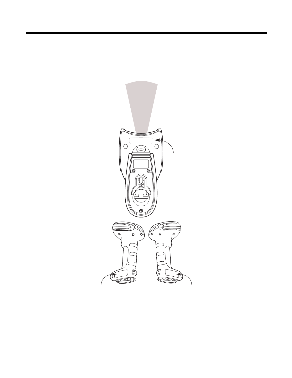
Required Safety Labels
Granit 1280i Scanner
Part Number, Serial
Number and Revision
Information location
Compliance
label location
Laser Label location
Laser Output
Page 7

Table of Contents
Chapter 1 - Getting Started
About This Manual ...............................................................................................................1-1
Unpacking Your Device .......................................................................................................1-1
Connecting the Device.........................................................................................................1-1
Reading Techniques ............................................................................................................1-2
Cyber Security Settings .......................................................................................................1-2
Setting Custom Defaults ......................................................................................................1-2
Resetting the Custom Defaults ............................................................................................1-2
Chapter 2 - Programming the Interface
Introduction ..........................................................................................................................2-1
Programming the Interface - Plug and Play .........................................................................2-1
RS232 Serial Port ................................................................................................................2-1
OPOS Mode...................................................................................................................2-1
Verifone
Gilbarco
Honeywell Bioptic Aux Port Configuration ...........................................................................2-2
Datalogic™ Magellan
NCR Bioptic Aux Port Configuration ....................................................................................2-3
Wincor Nixdorf Terminal Default Settings ............................................................................2-3
Wincor Nixdorf Beetle™ Terminal Default Settings .............................................................2-3
RS232 Modifiers ..................................................................................................................2-4
NCR Modifiers......................................................................................................................2-9
Scanner to Bioptic Communication....................................................................................2-10
®
Ruby Terminal Default Settings...........................................................................2-2
®
Terminal Default Settings ....................................................................................2-2
®
Aux Port Configuration....................................................................2-2
RS232 Baud Rate ..........................................................................................................2-4
RS232 Word Length: Data Bits, Stop Bits, and Parity ...................................................2-5
RS232 Handshaking ......................................................................................................2-6
RS232 Timeout ..............................................................................................................2-7
XON/XOFF.....................................................................................................................2-7
ACK/NAK .......................................................................................................................2-7
Communication Timeout ................................................................................................2-7
NAK Retries ...................................................................................................................2-8
Support BEL/CAN in ACK/NAK......................................................................................2-8
RS232 Defaults..............................................................................................................2-9
NCR ACK/NAK...............................................................................................................2-9
Block Check Character ..................................................................................................2-9
NCR Prefix .....................................................................................................................2-9
NCR Suffix ...................................................................................................................2-10
NCR Prefix/Suffix .........................................................................................................2-10
NCR NOF (Not-on-File) Error.......................................................................................2-10
Scanner-Bioptic Packet Mode......................................................................................2-11
Chapter 3 - Input/Output Settings
Power Save Mode................................................................................................................3-1
Power Up Beeper.................................................................................................................3-1
i
Page 8

Beep on BEL Character.......................................................................................................3-2
Good Read and Error Indicators..........................................................................................3-2
Beeper – Good Read.....................................................................................................3-2
Beeper Volume – Good Read........................................................................................3-2
Beeper Pitch – Good Read............................................................................................ 3-3
Beeper - Transmit Order................................................................................................3-3
Vibrate – Good Read..................................................................................................... 3-3
Beeper Pitch – Error ...................................................................................................... 3-4
Beeper Duration – Good Read ...................................................................................... 3-4
Number of Beeps – Good Read ....................................................................................3-5
Number of Beeps – Error............................................................................................... 3-5
Beeper Volume Max ...................................................................................................... 3-5
Laser Aimer ......................................................................................................................... 3-5
Laser Aimer - Scanning Pattern.....................................................................................3-5
Laser Aimer - Scanning Duration...................................................................................3-6
Laser Aimer - Good Read Pattern .................................................................................3-6
Laser Aimer - Good Read Duration ...............................................................................3-7
Aimer Delay ...................................................................................................................3-7
LED Indicators .....................................................................................................................3-8
LED Settings.................................................................................................................. 3-8
Good Read Delay ..........................................................................................................3-9
User-Specified Good Read Delay..................................................................................3-9
Out-Of-Stand Settings .........................................................................................................3-9
Out-of-Stand Defaults.................................................................................................... 3-9
Presentation Mode.......................................................................................................3-10
Manual Activation Mode ..............................................................................................3-10
End Manual Activation After Good Read..................................................................... 3-10
Manual Activation Laser Timeout - Trigger Settings.................................................... 3-11
Reread Delay.....................................................................................................................3-11
User-Specified Reread Delay ...................................................................................... 3-11
CodeGate
®
........................................................................................................................3-12
Character Activation Mode ................................................................................................3-12
Activation Character .................................................................................................... 3-12
End Character Activation After Good Read................................................................. 3-13
Character Activation Timeout ......................................................................................3-13
Character Deactivation Mode ............................................................................................3-13
Deactivation Character ................................................................................................ 3-14
Centering...........................................................................................................................3-14
Blinky Mode .......................................................................................................................3-15
Laser Scan Angle ..............................................................................................................3-15
Decode Security ................................................................................................................3-16
Continuous Scan Mode .....................................................................................................3-16
ii
Page 9

Output Sequence Overview...............................................................................................3-16
Output Sequence Editor ..............................................................................................3-16
To Add an Output Sequence .......................................................................................3-16
Other Programming Selections....................................................................................3-17
Output Sequence Editor ..............................................................................................3-18
Sequence Timeout.......................................................................................................3-18
Sequence Match Beeper .............................................................................................3-18
Partial Sequence .........................................................................................................3-19
Require Output Sequence ...........................................................................................3-19
No Read ............................................................................................................................3-20
Chapter 4 - Data Editing
Prefix/Suffix Overview .........................................................................................................4-1
To Add a Prefix or Suffix:............................................................................................... 4-1
To Clear One or All Prefixes or Suffixes........................................................................ 4-2
To Add a Carriage Return Suffix to All Symbologies..................................................... 4-2
Prefix Selections..................................................................................................................4-2
Suffix Selections..................................................................................................................4-2
Function Code Transmit ......................................................................................................4-3
Communication Check Character........................................................................................ 4-3
Intercharacter, Interfunction, and Intermessage Delays......................................................4-3
Intercharacter Delay ......................................................................................................4-4
User Specified Intercharacter Delay.............................................................................. 4-4
Interfunction Delay.........................................................................................................4-4
Intermessage Delay....................................................................................................... 4-5
Chapter 5 - Data Formatting
Data Format Editor Introduction .......................................................................................... 5-1
Add a Data Format ..............................................................................................................5-1
Other Programming Selections......................................................................................5-2
Terminal ID Table................................................................................................................5-3
Data Format Editor Commands...........................................................................................5-3
Move Commands...........................................................................................................5-6
Search Commands........................................................................................................ 5-7
Miscellaneous Commands.............................................................................................5-9
Data Formatter ..................................................................................................................5-11
Data Format Non-Match Error Tone............................................................................ 5-12
Primary/Alternate Data Formats........................................................................................5-12
Single Scan Data Format Change............................................................................... 5-13
Chapter 6 - Symbologies
All Symbologies...................................................................................................................6-1
Message Length Description...............................................................................................6-1
Codabar...............................................................................................................................6-2
Codabar Concatenation................................................................................................. 6-3
iii
Page 10

Code 39 ...............................................................................................................................6-5
Code 32 Pharmaceutical (PARAF)................................................................................ 6-6
Full ASCII....................................................................................................................... 6-7
Code 39 Code Page ...................................................................................................... 6-7
Interleaved 2 of 5.................................................................................................................6-8
Matrix 2 of 5.........................................................................................................................6-9
NEC 2 of 5.........................................................................................................................6-11
Code 93 .............................................................................................................................6-12
Code 93 Code Page .................................................................................................... 6-13
Straight 2 of 5 Industrial (three-bar start/stop)...................................................................6-14
Straight 2 of 5 IATA (two-bar start/stop)............................................................................6-15
Code 11 .............................................................................................................................6-16
Code 128...........................................................................................................................6-17
ISBT 128 Concatenation..............................................................................................6-18
GS1-128 ............................................................................................................................ 6-23
Telepen..............................................................................................................................6-24
UPC-A ...............................................................................................................................6-25
UPC-A/EAN-13
with Extended Coupon Code .......................................................................................... 6-28
UPC-A/Code 128 Coupon Code Output...................................................................... 6-28
UPC-A Number System 5 Addenda Required............................................................. 6-29
Coupon GS1 DataBar Output...................................................................................... 6-30
UPC-E0 .............................................................................................................................6-31
EAN/JAN-13 ......................................................................................................................6-34
Convert UPC-A to EAN-13 ..........................................................................................6-34
ISBN Translate ............................................................................................................6-40
ISSN Translate ............................................................................................................6-41
EAN/JAN-8 ........................................................................................................................ 6-42
MSI .................................................................................................................................... 6-44
Plessey Code ....................................................................................................................6-46
GS1 DataBar Omnidirectional ...........................................................................................6-47
GS1 DataBar Limited.........................................................................................................6-48
GS1 DataBar Expanded....................................................................................................6-49
Trioptic Code ..................................................................................................................... 6-50
GS1 Emulation ..................................................................................................................6-50
China Post (Hong Kong 2 of 5)..........................................................................................6-51
Chapter 7 - Utilities
To Add a Test Code I.D. Prefix to All Symbologies.............................................................7-1
Show Software Revision......................................................................................................7-1
Show Data Format...............................................................................................................7-1
Test Menu............................................................................................................................7-1
TotalFreedom ...................................................................................................................... 7-1
Application Plug-Ins (Apps) .................................................................................................7-2
EZConfig-Scanning Introduction..........................................................................................7-2
Installing EZConfig-Scanning from the Web.................................................................. 7-3
Resetting the Factory Defaults ............................................................................................7-3
iv
Page 11

Chapter 8 - Serial Programming Commands
Conventions.........................................................................................................................8-1
Menu Command Syntax......................................................................................................8-1
Query Commands ...............................................................................................................8-1
Responses..................................................................................................................... 8-2
Serial Trigger Commands....................................................................................................8-3
Read Time-Out .............................................................................................................. 8-3
Resetting the Custom Defaults............................................................................................8-3
Menu Commands ................................................................................................................ 8-4
Chapter 9 - Product Specifications
Granit 1280i Industrial Corded Scanner Product Specifications.......................................... 9-1
Depth of Field Charts...........................................................................................................9-2
Typical Performance .....................................................................................................9-2
Guaranteed Performance ............................................................................................9-2
....................................................................................................................................... 9-3
Standard Connector Pinouts ...............................................................................................9-4
Serial Output.................................................................................................................. 9-4
Chapter 10 - Maintenance
Repairs .............................................................................................................................. 10-1
Maintenance......................................................................................................................10-1
Cleaning the Scanner ..................................................................................................10-1
Cleaning the Window................................................................................................... 10-1
Inspecting Cords and Connectors ...............................................................................10-1
Replacing Cables ..............................................................................................................10-1
Replacing an Interface Cable ......................................................................................10-2
Troubleshooting.................................................................................................................10-2
Chapter 11 - Customer Support
Technical Assistance.........................................................................................................11-1
Product Service and Repair...............................................................................................11-1
Appendix A - Reference Charts
Symbology Charts ...............................................................................................................A-1
Linear Symbologies .......................................................................................................A-1
Postal Symbologies .......................................................................................................A-2
ASCII Conversion Chart (Code Page 1252)........................................................................A-2
Lower ASCII Reference Table.............................................................................................A-3
ISO 2022/ISO 646 Character Replacements ......................................................................A-7
Unicode Key Maps ..............................................................................................................A-9
v
Page 12

vi
Page 13
1
Getting Started
About This Manual
This User’s Guide provides installation and programming instructions for the Granit 1280i corded industrial scanners. Product
specifications, dimensions, warranty, and customer support information are also included.
Honeywell bar code scanners are factory programmed for the most common terminal and communications settings. If you need
to change these settings, programming is accomplished by scanning the bar codes in this guide.
An asterisk (*) next to an option indicates the default setting.
Unpacking Your Device
After you open the shipping carton containing the product, take the following steps:
• Check for damage during shipment. Report damage immediately to the carrier who delivered the carton.
• Make sure the items in the carton match your order.
• Save the shipping container for later storage or shipping.
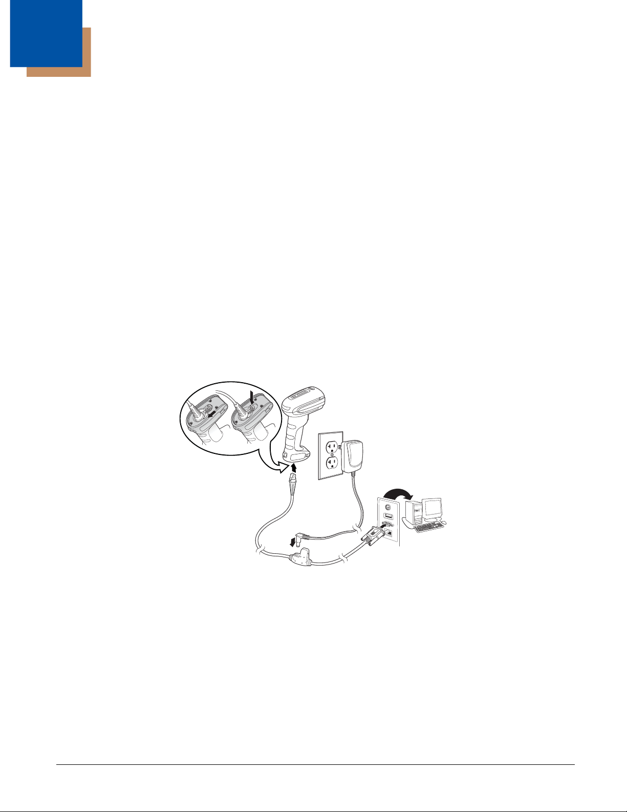
Connecting the Device
1. Turn off power to the terminal/computer.
2. Connect the appropriate interface cable to the scanner.
Note: For the scanner to work properly, you must have the correct cable for your type of terminal/computer.
3. Make sure the cable is pushed tightly into the scanner. Loosen the locking plate and slide it over the base of the cable
connector to lock the cable in place. Tighten the screw.
4. Plug the serial connector into the serial port on your computer. Tighten the two screws to secure the connector to the port.
5. Once the scanner has been fully connected, power up the computer.
6. Plug in the AC adapter, if applicable.
This interface programs 9600 baud, 8 data bits, no parity, and 1 stop bit.
1 - 1
Page 14

Reading Techniques
Set Custom Defaults
Save Custom Defaults
Activate Custom Defaults
The Granit 1280i scanner has a bright red scanning line that corresponds to the scanner’s horizontal field of view.
The scanning line is smaller when the scanner is closer to the code and larger when it is farther from the code. Symbologies
with smaller bars or elements (mil size) should be read closer to the unit. Symbologies with larger bars or elements (mil size)
should be read farther from the unit. To read single or multiple symbols (on a page or on an object), hold the scanner at an
appropriate distance from the target, pull the trigger, and center the scanning line on the symbol. If the code being scanned is
highly reflective (e.g., laminated), it may be necessary to tilt the code up 15° to 18° to prevent unwanted reflection.
Cyber Security Settings
Honeywell scanners have additional settings aimed at preventing cyber attacks. You may want to restrict the ability to program
your device with menu codes or serial commands, or you may want to disable firmware upgrades to your device. Honeywell’s
Cyber Security settings allow you to secure your device by restricting these features. Please contact the nearest technical support office (see Technical Assistance on page 11-1) for further information.
Setting Custom Defaults
You have the ability to create a set of menu commands as your own, custom defaults. To do so, scan the Set Custom Defaults
bar code below before scanning the menu commands for your custom defaults. If a menu command requires scanning numeric
codes from the back cover, then a Save code, that entire sequence will be saved to your custom defaults. When you have
entered all the commands you want to save for your custom defaults, scan the Save Custom Defaults bar code.
You may have a series of custom settings and want to correct a single setting. To do so, just scan the new setting to overwrite
the old one. For example, if you had previously saved the setting for Beeper Volume at Low to your custom defaults, and decide
you want the beeper volume set to High, just scan the Set Custom Defaults bar code, then scan the Beeper Volume High
menu code, and then Save Custom Defaults. The rest of the custom defaults will remain, but the beeper volume setting will be
updated.
Resetting the Custom Defaults
If you want the custom default settings restored to your scanner, scan the Activate Custom Defaults bar code below. This is
the recommended default bar code for most users. It resets the scanner to the custom default settings. If there are no custom
defaults, it will reset the scanner to the factory default settings. Any settings that have not been specified through the custom
defaults will be defaulted to the factory default settings.
1 - 2
Page 15
2
RS232 Interface
OPOS Mode
Programming the Interface
Introduction
This chapter describes how to program your system for the desired interface.
Programming the Interface - Plug and Play
Plug and Play bar codes provide instant scanner set up for commonly used interfaces.
Note: After you scan one of the codes, power cycle the host terminal to have the interface in effect.
RS232 Serial Port
The RS232 Interface bar code is used when connecting to the serial port of a PC or terminal. The following RS232 Interface
bar code also programs a carriage return (CR) and a line feed (LF) suffix, baud rate, and data format as indicated below. It also
changes the trigger mode to manual.
Option Setting
Baud Rate 9600 bps
Data Format 8 data bits, no parity bit, 1 stop bit
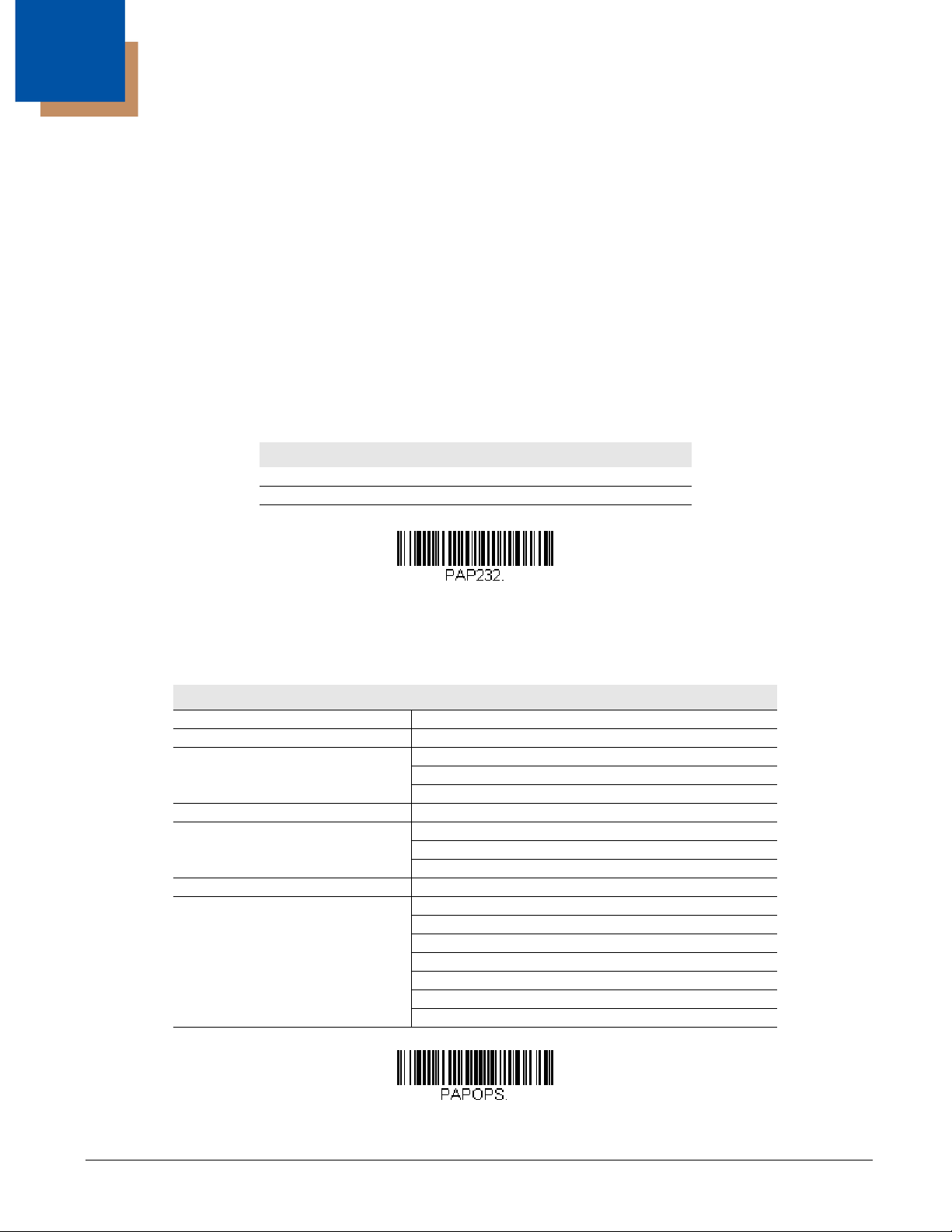
OPOS Mode
The following bar code configures your engine for OPOS (OLE for Retail Point of Sale) by modifying the following OPOSrelated settings:
Option Setting
Interface RS232
Baud Rate 38400
RS232 Handshaking Flow Control, No Timeout
XON/XOFF Off
ACK/NAK Off
Data Bits, Stop Bits, and Parity 8 Data, 1 Stop, Parity None
Prefix/Suffix
Intercharacter Delay Off
Symbologies Enable UPC-A with check digit and number system
Clear All Prefixes and Suffixes
Add Code ID and AIM ID Prefix
Add CR Suffix
Enable UPC-E0 with check digit
Enable EAN/JAN-8 with check digit
Enable EAN/JAN-13 with check digit
Enable Code 128
Enable Code 39
Enable OPOS with automatic disable off
2 - 1
Page 16

Verifone® Ruby Terminal Default Settings
Verifone Ruby Settings
Gilbarco Settings
Honeywell Bioptic Settings
Datalogic Magellan Settings
Scan the following Plug and Play code to program the scanner for a Verifone Ruby terminal. This bar code sets the baud rate to
1200 bps and the data format to 8 data bits, no parity bit, 1 stop bit. It also adds a line feed (LF) suffix and programs the following prefixes for each symbology:
Symbology Prefix
UPC-A A
UPC-E A
EAN-8 FF
EAN-13 F
Gilbarco® Terminal Default Settings
Scan the following Plug and Play code to program the scanner for a Gilbarco terminal. This bar code sets the baud rate to 2400
bps and the data format to 7 data bits, even parity, 2 stop bits. It also adds a carriage return (CR) suffix and programs the following prefixes for each symbology:
Symbology Prefix
UPC-A A
UPC-E E0
EAN-8 FF
EAN-13 F
Honeywell Bioptic Aux Port Configuration
Scan the following Plug and Play code to program the scanner for a Honeywell bioptic scanner auxiliary port configuration. This
bar code sets the baud rate to 38400 bps and the data format to 8 data bits, no parity, 1 stop bit.
Datalogic™ Magellan® Aux Port Configuration
Scan the following Plug and Play code to program the scanner for a Datalogic Magellan auxiliary port configuration. This bar
code sets the baud rate to 9600 bps and the data format to 8 data bits, no parity, 1 stop bit.
2 - 2
Page 17
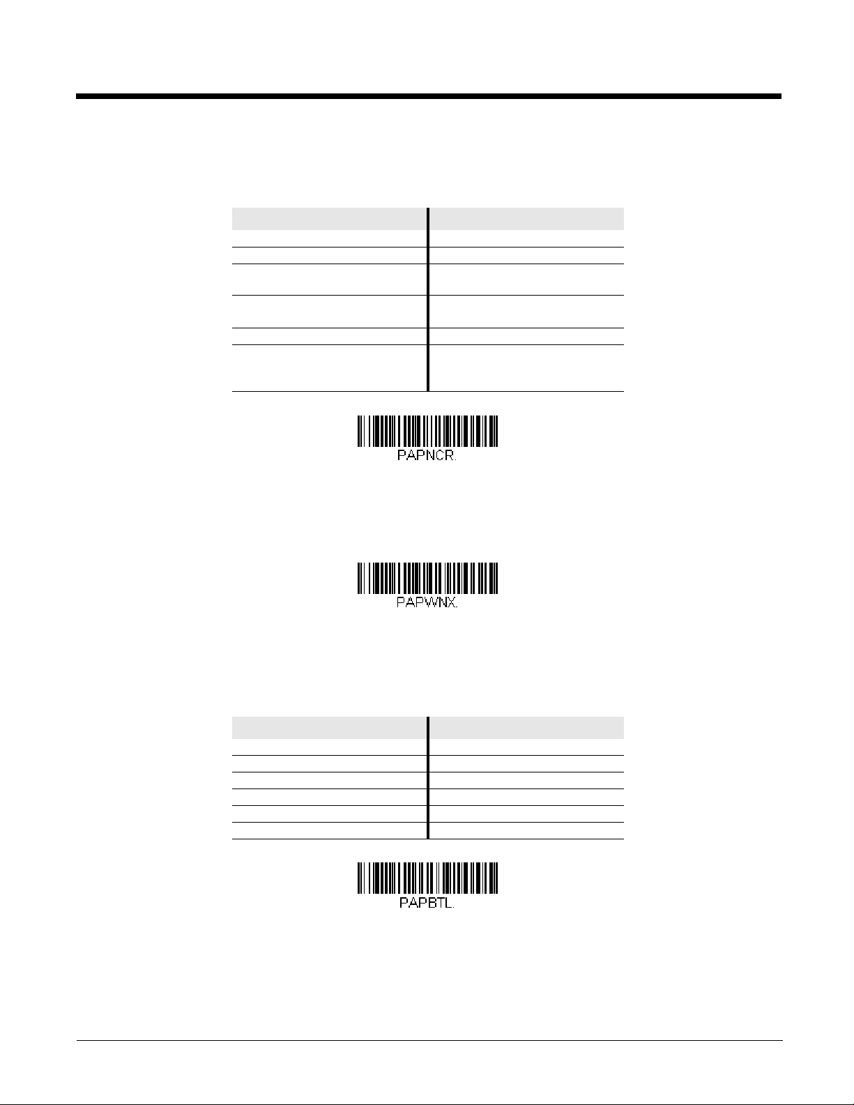
NCR Bioptic Aux Port Configuration
NCR Bioptic Settings
Wincor Nixdorf Terminal Settings
Wincor Nixdorf Beetle Settings
Scan the following Plug and Play code to program the scanner for an NCR bioptic scanner auxiliary port configuration. The following prefixes are programmed for each symbology:
Symbology Prefix Symbology Prefix
UPC-A A Interleaved 2 of 5 b
UPC-E E0 Code 128 f
GS1 DataBar
Omnidirecitonal
EAN-8 FF GS1 DataBar
Expanded
EAN-13 F Codabar N
Code 39 a Code 32
Pharmaceutical
(PARAF)
r
r
a
Wincor Nixdorf Terminal Default Settings
Scan the following Plug and Play code to program the scanner for a Wincor Nixdorf terminal. This bar code sets the baud rate
to 9600 bps and the data format to 8 data bits, no parity, 1 stop bit.
Wincor Nixdorf Beetle™ Terminal Default Settings
Scan the following Plug and Play code to program the scanner for a Wincor Nixdorf Beetle terminal. The following prefixes are
programmed for each symbology:
Symbology Prefix Symbology Prefix
Code 128 K EAN-13 A
Code 93 L GS1-128 P
Codabar N Interleaved 2 of 5 I
UPC-A A0 Plessey O
UPC-E C Straight 2 of 5 IATA H
EAN-8 B All other bar codes M
2 - 3
Page 18
RS232 Modifiers
300
600
1200
2400
4800
* 9600
19200
38400
57,600
115,200
RS232 Baud Rate
Baud Rate sends the data from the scanner to the terminal at the specified rate. The host terminal must be set for the
same baud rate as the scanner. Default = 9600.
2 - 4
Page 19
RS232 Word Length: Data Bits, Stop Bits, and Parity
7 Data, 1 Stop, Parity Even
7 Data, 1 Stop, Parity None
7 Data, 1 Stop, Parity Odd
7 Data, 2 Stop, Parity Even
7 Data, 2 Stop Parity None
7 Data, 2 Stop, Parity Odd
8 Data, 1 Stop, Parity Even
* 8 Data, 1 Stop, Parity None
8 Data, 1 Stop, Parity Odd
8 Data, 1 Stop, Parity Mark
Data Bits sets the word length at 7 or 8 bits of data per character. If an application requires only ASCII Hex characters 0
through 7F decimal (text, digits, and punctuation), select 7 data bits. For applications that require use of the full ASCII set,
select 8 data bits per character. Default = 8.
Stop Bits sets the stop bits at 1 or 2. Default = 1.
Parity provides a means of checking character bit patterns for validity.
Default = None.
2 - 5
Page 20
RS232 Handshaking
* RTS/CTS Off
* RTS/CTS Off, RTS
Inactive
Flow Control, No Timeout
Character-Based Flow Control,
No Timeout
Two-Direction Flow Control
Flow Control with Timeout
Character-Based Flow Control
with Timeout
RS232 Handshaking allows control of data transmission from the scanner using software commands from the host device.
RTS/CTS Off: RTS/CTS is turned off so no data flow control is used, but RTS is still active.
RTS/CTS Off, RTS Inactive: RTS/CTS is turned off so no data flow control is used and RTS is inactive.
Flow Control, No Timeout: The scanner asserts RTS when it has data to send, and will wait indefinitely for CTS to be
asserted by the host.
Character-Based Flow Control, No Timeout: The scanner asserts RTS when it has a character to send, and will wait
indefinitely for CTS to be asserted by the host
Two-Direction Flow Control: The scanner asserts RTS when it is OK for the host to transmit. The host asserts CTS
when it is OK for the device to transmit.
Flow Control with Timeout: The scanner asserts RTS when it has data to send and waits for a delay (see RS232
Timeout on page 2-7) for CTS to be asserted by the host. If the delay time expires and CTS is not asserted, the device
transmit buffer is cleared and scanning may resume.
Character-Based Flow Control with Timeout: The scanner asserts RTS when it has a character to send and waits for a
delay (see RS232 Timeout on page 2-7) for CTS to be asserted by the host. If the delay time expires and CTS is not
asserted, the device transmit buffer is cleared and scanning may resume.
Default = RTS/CTS Off.
2 - 6
Page 21
RS232 Timeout
RS232 Timeout
XON/XOFF On
* XON/XOFF Off
ACK/NAK On
* ACK/NAK Off
Communication Timeout
When using Flow Control with Timeout, you must program the length of the delay you want to wait for CTS from the host.
Set the length (in milliseconds) for a timeout by scanning the bar code below, then setting the timeout (from 1-65535 milliseconds) by scanning digits from the inside back cover, then scanning Save.
XON/XOFF
Standard ASCII control characters can be used to tell the scanner to start sending data (XON/XOFF On) or to stop sending
data (XON/XOFF Off). When the host sends the XOFF character (DC3, hex 13) to the scanner, data transmission stops.
To resume transmission, the host sends the XON character (DC1, hex 11). Data transmission continues where it left off
when XOFF was sent. Default = XON/XOFF Off.
ACK/NAK
After transmitting data, the scanner waits for an ACK character (hex 06) or a NAK character (hex 15) response from the
host. If ACK is received, the communications cycle is completed and the scanner looks for more bar codes. If NAK is
received, the last set of bar code data is retransmitted and the scanner waits for ACK/NAK again. Turn on the ACK/NAK
protocol by scanning the ACK/NAK On bar code below. To turn off the protocol, scan ACK/NAK Off. Default = ACK/NAK
Off.
Communication Timeout
This allows you to set the length (in milliseconds) for a timeout for the host ACK/NAK response. Scan the bar code below,
then set the timeout (from 1-65535 milliseconds) by scanning digits from the Programming Chart, then scanning Save.
Default = 2000 ms.
2 - 7
Page 22
Timeout Retries
Timeout Retries
O
f
f
* On
NAK Retries
BEL/CAN On
* BEL/CAN Off
This setting limits the number of Communication Timeout retries. If the Timeout Retries is set to 0, the transmission is
terminated after the initial Communication Timeout. Scan the bar code below, then set the number of retries (from 0-
255) by scanning digits from the Programming Chart, then scanning Save. (5 is the recommended setting.) Default =
0.
Communication Timeout Beeper
This selection programs the scanner to issue an error beep when a communication timeout has occurred. The error
beep sound is programmed using Number of Beeps – Error (page 3-5). Default = On.
NAK Retries
This selection limits the number of NAK retries that can occur in ACK/NAK mode. Scan the bar code below, then set the
number of retries (from 0-255) by scanning digits from the Programming Chart, then scanning Save. (5 is the recommended setting.) Default = 0, or disabled.
Support BEL/CAN in ACK/NAK
This protocol responds to <BEL> and <CAN> commands when in ACK/NAK mode. The scanner sounds an error tone
when a <BEL> command is sent from the host. <CAN> terminates the transmission. Default = BEL/CAN Off.
2 - 8
Page 23
RS232 Defaults
RS232 Defaults
* NCR ACK/NAK Off
NCR ACK/NAK On
* Transmit
Don’t Transmit
NCR Prefix
If you want the custom RS232 default settings restored to your scanner, scan the RS232 Defaults bar code below. This
resets the scanner to the custom default settings (see Setting Custom Defaults on page 1-2). If there are no custom
defaults, it will reset the scanner to the factory default settings. Any settings that have not been specified through the custom defaults will be restored to the factory default settings.
NCR Modifiers
NCR ACK/NAK
This is an NCR communication protocol for ACK/NAK processing. Default = NCR ACK/NAK Off.
Block Check Character
When this selection is set to Transmit, the NCR Block Check Character (BCC) is expected with incoming messages and
transmitted with outgoing messages. Default = Transmit.
NCR Prefix
This selection allows you to program an NCR-specific prefix. Refer to the ASCII Conversion Chart (Code Page
1252), page A-2 to find the hex equivalent for the characters you want for the NCR prefix (typically, 02 for STX). Scan the
bar code below, then set the hex number (from 0-FF) by scanning digits from the Programming Chart, then scanning Save.
Default = 0.
2 - 9
Page 24
NCR Suffix
NCR Suffix
Transmit
* Don’t Transmit
On
* Off
This selection allows you to program an NCR-specific suffix. Refer to the ASCII Conversion Chart (Code Page 1252), page
A-2 to find the hex equivalent for the characters you want for the NCR suffix (typically, 03 for ETX). Scan the bar code
below, then set the hex number (from 0-FF) by scanning digits from the Programming Chart, then scanning Save. Default
= 0.
NCR Prefix/Suffix
When set to Tra ns mit, both the NCR prefix and suffix are transmitted with bar codes. Usually, prefixes and suffixes are
programmed using the Data Editing selections (see Data Editing beginning on page 4-1), however, the following commands
override any other prefix/suffix settings. Default = Don’t Transmit.
NCR NOF (Not-on-File) Error
A scanner receives an NOF (Not on File) command from the POS whenever it cannot cross-reference the bar code to a
price parameter. When set to On, the error tone sounds (set via Number of Beeps – Error, page 3-5) for an NOF, and dis-
ables the scanner while the cashier looks up the price manually. When set to Off, no sound is emitted for an NOF. Default
= Off.
Scanner to Bioptic Communication
The following settings are used to set up communication between Honeywell scanners and bioptic scanners.
Note: The scanner’s baud rate must be set to 38400 and the RS232 timeout must be set to 3000 in order to communicate with
a bioptic scanner. See "RS232 Modifiers" on page 2-4, and RS232 Timeout on page 2-7 for further information.
2 - 10
Page 25

Scanner-Bioptic Packet Mode
* Packet Mode Off
Packet Mode On
Packet Mode On must be scanned to set the scanner’s format so it is compatible with a bioptic scanner. Default = Packet
Mode Off.
2 - 11
Page 26

2 - 12
Page 27

3
* Off
Sleep Mode Only
Hibernate Mode
Power Save Mode Timeout
Power Up Beeper Off -
Scanner
Input/Output Settings
Power Save Mode
Power Save Mode allows you to automatically set the conditions under which the scanner idles, sleeps, and wakes up. When
Off is selected, no power saving is used and the scanner remains powered on until the trigger is pressed.
When Sleep Mode is selected, the scanner goes into sleep mode (powered off) after the time interval set using Power Save
Mode Timeout (page 3-1), during which there is no activity. This provides significant power savings over the Off setting.
When Hibernate Mode is selected, the scanner goes into idle mode after the time interval set using Power Save Mode Timeout
(page 3-1), during which there is no activity. After the same time interval has elapsed with no activity while the scanner is in idle
mode, the scanner goes into sleep mode (powered off). This provides additional power savings over the Sleep Mode setting,
but the scanner takes longer to wake up.
Default = Off.
Power Save Mode Timeout
Use this selection to set a timeout (in seconds) for the scanner when using Power Save Mode. When this time has
elapsed with no activity, the scanner will enter the Power Save Mode selected. After scanning the Power Save Mode
Timeout bar code, set the timeout duration (from 0-65535 seconds) by scanning digits on the Programming Chart
inside the back cover, then scanning Save. Default = 600 seconds.
Power Up Beeper
The scanner can be programmed to beep when it’s powered up. Scan the Off bar code(s) if you don’t want a power up beep.
Default = Power Up Beeper On - Scanner.
3 - 1
Page 28

Beep on BEL Character
* Power Up Beeper On -
Scanner
*Beep on BEL Off
Beep on BEL On
Beeper - Good Read Off
* Beeper - Good Read On
Low
Medium
* High
You may wish to force the scanner to beep upon a command sent from the host. If you scan the Beep on BEL On bar code
below, the scanner will beep every time a BEL character is received from the host. Default = Beep on BEL Off.
Good Read and Error Indicators
Beeper – Good Read
The beeper may be programmed On or Off in response to a good read. Turning this option off only turns off the beeper
response to a good read indication. All error and menu beeps are still audible. Default = Beeper - Good Read On.
Beeper Volume – Good Read
The beeper volume codes modify the volume of the beep the scanner emits on a good read. Default = High.
3 - 2
Page 29
Beeper Pitch – Good Read
Off
Low (1600 Hz)
* Medium (3200 Hz)
High (4200 Hz)
* Before Transmission
After Transmission
Vibrate- Good Read Off
* Vibrate- Good Read On
The beeper pitch codes modify the pitch (frequency) of the beep the scanner emits on a good read. Default = Medium.
Beeper - Transmit Order
The beeper transmit order determines when the good read beep occurs. The scanner can be set to emit the good read
beep either before or after data transmission. Default = Before Transmission.
Vibrate – Good Read
The scanner vibrates once when a bar code is successfully read, and twice when a programming bar code is successfully
read. When a programming bar code is unsuccessful, the scanner emits one long vibration (2 times the Vibrate Duration
length). The trigger cannot be used again until the vibration has ended. Scan Vibrate - Good Read Off to keep the scanner from vibrating. This setting may be preferable if you need to scan multiple bar codes in succession and do not want to
wait till the vibration has ended. Default = Vibrate - Good Read On.
3 - 3
Page 30

Vibrate Duration
Vibrate Duration
* Razz (100 Hz)
Medium (3250 Hz)
High (4200 Hz)
* Normal Beep
Short BeepShort Beep
If you want to set the length for the good read vibration, scan the bar code below, then set the duration (from 100 2,000 milliseconds) by scanning digits from the inside back cover, then scanning Save. If you need to scan multiple bar
codes in succession, you may wish to set a short duration time, since the trigger cannot be used until the vibration has
ended. Default = 300 ms.
Beeper Pitch – Error
The beeper pitch codes modify the pitch (frequency) of the sound the scanner emits when there is a bad read or error.
Default = Razz.
Beeper Duration – Good Read
The beeper duration codes modify the length of the beep the scanner emits on a good read. Default = Normal.
3 - 4
Page 31

Number of Beeps – Good Read
Number of Good Read Beeps/LED Flashes
Number of Error Beeps/LED Flashes
Beeper Volume Max
Laser Aimer - Scanning
Pattern Off
Laser Aimer - Scanning
Laser Dot
The number of beeps of a good read can be programmed from 1 - 9. The same number of beeps will be applied to the
beeper and LED in response to a good read. For example, if you program this option to have five beeps, there will be five
beeps and five LED flashes in response to a good read. The beeps and LED flashes are in sync with one another. To
change the number of beeps, scan the bar code below and then scan a digit (1-9) bar code and the Save bar code on the
Programming Chart inside the back cover of this manual. Default = 1.
Number of Beeps – Error
The number of beeps and LED flashes emitted by the scanner for a bad read or error can be programmed from 1 - 9. For
example, if you program this option to have five error beeps, there will be five error beeps and five LED flashes in response
to an error. To change the number of error beeps, scan the bar code below and then scan a digit (1-9) bar code and the
Save bar code on the Programming Chart inside the back cover of this manual. Default = 1.
Beeper Volume Max
Scan the following bar code to set all error and good read beeps to the maximum volume. This feature also sets the Beeper
Pitch – Good Read to the highest level.
Laser Aimer
Laser Aimer - Scanning Pattern
To set the laser light pattern that appears when scanning a bar code, you must first enter an aimer delay (see Aimer Delay
on page 3-7). Then scan one of the following bar codes to set a new scanning pattern.
Default = 10 Segment Line.
3 - 5
Page 32

Laser Aimer - Scanning Duration
Laser Aimer - Scanning
Blinking Dot
Laser Aimer - Scanning
3 Segment Line
Laser Aimer - Scanning
5 Segment Line
* Laser Aimer - Scanning
10 Segment Line
Laser Aimer - Scanning Duration
Laser Aimer - Good Read
Pattern Off
Laser Aimer - Good Read
3 Segment Line
Laser Aimer - Good Read
5 Segment Line
Use the Laser Aimer - Scanning Duration bar code to specify how long you want the Laser Aimer - Scanning Pattern to
remain on after the trigger is released. Scan the bar code below, then set the duration (from 0 - 65535 milliseconds) by
scanning digits from the inside back cover, then scanning Save. Default = 0 ms.
Laser Aimer - Good Read Pattern
Once a bar code has been successfully read, you may want the laser light to remain on, but to display a different pattern
than the scanning pattern. This gives the operator an additional visual indicator that the bar code was successfully read.
Scan one of the bar codes below to program your device for a Good Read Pattern. Default = 10 Segment Line.
3 - 6
Page 33

Laser Aimer - Good Read Duration
* Laser Aimer - Good Read
10 Segment Line
Laser Aimer - Good Read Duration
200 milliseconds
400 milliseconds
* Off (no delay)
Delay Duration
Use the Laser Aimer - Good Read Duration bar code to specify how long you want the Laser Aimer - Good Read Pattern
to remain on after a bar code has been successfully read. Scan the bar code below, then set the duration (from 0 - 65535
milliseconds) by scanning digits from the inside back cover, then scanning Save. Default = 0 ms.
Aimer Delay
The aimer delay allows a delay time for the operator to aim the scanner before the bar code is scanned. Use these codes
to set the time between when the trigger is pulled and when the bar code is scanned. During the delay time, the aiming
light will appear, but scanning will not begin until the delay time is over. Default = Off.
User-Specified Aimer Delay
If you want to set your own length for the duration of the delay, scan the bar code below, then set the time-out by scanning digits (0 - 4,000 ms) from the Programming Chart inside the back cover of this manual, then scan Save.
3 - 7
Page 34

LED Indicators
Red LED Off
Green LED Off
Red LED On with Good Scan
* Green LED On with Good Scan
* Red LED On with Laser
Green LED On with Laser
Red LED On when CodeGate
Disabled
Green LED On when CodeGate
Disabled
Red LED On with CTS
Green LED On with CTS
The green and red LEDs can be programmed to be On or Off and at different brightness levels to indicate various scanner
states. Use the following bar codes to program the LED indicators.
LED Settings
Default = Red LED On with Laser, Green LED On with Good Scan.
3 - 8
Page 35

Good Read Delay
* No Delay
Short Delay (500 ms)
Medium Delay (1,000 ms)
Long Delay (1,500 ms)
User-Specified Good Read Delay
Out-of-Stand Defaults
This sets the minimum amount of time before the scanner can read another bar code. Default = 0 ms (No Delay).
User-Specified Good Read Delay
If you want to set your own length for the good read delay, scan the bar code below, then set the delay (from 0 - 30,000 milliseconds) by scanning digits from the inside back cover, then scanning Save.
Out-Of-Stand Settings
The following settings program the scanner’s behavior when it is out of the stand, or hand-held.
Note: The Granit 1280i does not support In-Stand settings. It supports only the standard Honeywell Out-of-Stand settings.
Caution: When working with Out-of-Stand settings, enable the settings you want before disabling those you do not
want to use. If you disable settings first, you may program the scanner so it is unable to read bar codes. if
this happens, power cycle the scanner and scan the defaults bar code on page 1-2.
Out-of-Stand Defaults
If you want the Out-of-Stand default settings restored to your scanner, scan the Out-of-Stand Defaults bar code below.
This resets the scanner to the custom default settings (see Setting Custom Defaults on page 1-2). If there are no custom
defaults, it will reset the scanner to the factory default settings. Any settings that have not been specified through the custom defaults will be defaulted to the factory default settings.
3 - 9
Page 36

Presentation Mode
Presentation Mode Out-
of-Stand
Manual Activation Mode Off
Out-of-Stand
* Manual Activation Mode On
Out-of-Stand
Do Not End Manual Activation
After Good Read Out-of-Stand
* End Manual Activation After
Good Read Out-of-Stand
When the scanner is in Presentation Mode, it automatically detects bar codes, then scans and transmits the data. To set
the time period before the scanner can read the same bar code a second time use Reread Delay (page 3-11). To return to
trigger scanning, scan the Out-of-Stand Defaults bar code, above.
Manual Activation Mode
In Manual Activation Mode, you must press the trigger to scan a bar code. The scanner scans until a bar code is read, or
until the trigger is released. Default = Manual Activation On Out-of-Stand.
End Manual Activation After Good Read
After a bar code is successfully read, the laser can be programmed either to remain on and scanning, or to turn off. When
End Manual Activation After Good Read is enabled, the laser turns off and stops scanning after a good read. If you scan
Do Not End Manual Activation After Good Read, the laser remains on after a good read, but the trigger must be pressed
to scan the next bar code. Default = End Manual Activation After Good Read Out-of-Stand.
3 - 10
Page 37

Manual Activation Laser Timeout - Trigger Settings
Laser Timeout - Trigger Hold
Out-of-Stand
Laser Timeout - Trigger
Release Out-of-Stand
Short (500 ms)
* Medium (750 ms)
Long (1000 ms)
Extra Long (2000 ms)
User-Specified Reread Delay
You can set a timeout for the length of time the laser remains on and attempting to decode bar codes when the trigger is
held down, and after it is released. Set the length (in milliseconds) for a timeout by scanning one of the following bar codes,
then setting the timeout (from 1-65535 milliseconds) by scanning digits from the Programming Chart, then scanning Save.
Default = Trigger Hold Out-of-Stand 30,000 ms, Trigger Release Out-of-Stand 0.
Reread Delay
This sets the time period before the scanner can read the same bar code a second time. Setting a reread delay protects against
accidental rereads of the same bar code. Longer delays are effective in minimizing accidental rereads. Use shorter delays in
applications where repetitive bar code scanning is required. Reread Delay only works when in a Presentation Mode (see page
3-10). Default = Medium.
User-Specified Reread Delay
If you want to set your own length for the reread delay, scan the bar code below, then set the delay (from 0-30,000 milliseconds) by scanning digits from the inside back cover, then scanning Save.
3 - 11
Page 38

CodeGate
CodeGate Off
Out-of-Stand
* CodeGate On
Out-of-Stand
* Off
On
Activation Character
When CodeGate is On, the trigger is used to allow decoded data to be transmitted to the host system. The scanner remains on,
scanning and decoding bar codes, but the bar code data is not transmitted until the trigger is pressed. When CodeGate is Off,
bar code data is transmitted when it is decoded. Default = CodeGate On Out-of-Stand.
®
Character Activation Mode
You may use a character sent from the host to trigger the scanner to begin scanning. When the activation character is received,
the scanner continues scanning until either the Character Activation Timeout (page 3-13), the deactivation character is received
(see Deactivation Character on page 3-14), or a bar code is transmitted. Scan the following On bar code to use character activation, then use Activation Character (following) to select the character you will send from the host to start scanning. Default =
Off.
Activation Character
This sets the character used to trigger scanning when using Character Activation Mode. On the ASCII Conversion Chart
(Code Page 1252), page A-2, find the hex value that represents the character you want to use to trigger scanning. Scan
the following bar code, then use the Programming Chart to read the alphanumeric combination that represents that ASCII
character. Scan Save to finish. Default = 18 [CAN].
3 - 12
Page 39

End Character Activation After Good Read
Do Not End Character Activation
After Good Read
* End Character Activation After
Good Read
Character Activation Timeout
* Off
On
After a bar code is successfully detected and read from the scanner, the illumination can be programmed either to remain
on and scanning, or to turn off. When End Character Activation After Good Read is enabled, the illumination turns off
and stops scanning after a good read. If you scan Do Not End Character Activation After Good Read, the illumination
remains on after a good read. Default = End Character Activation After Good Read.
Character Activation Timeout
You can set a timeout for the length of time the illumination remains on and attempting to decode bar codes when using
Character Activation Mode. Set the length (in milliseconds) for a timeout by scanning the following bar code, then setting
the timeout (from 1-65,535 milliseconds) by scanning digits from the Programming Chart inside the back cover of this manual, then scanning Save. Default = 5000 ms.
Character Deactivation Mode
If you have sent a character from the host to trigger the scanner to begin scanning, you can also send a deactivation character
to stop scanning. Scan the following On bar code to use character deactivation, then use Deactivation Character (following) to
select the character you will send from the host to terminate scanning. Default = Off.
3 - 13
Page 40

Deactivation Character
Deactivation Character
0
Bar Code 1
Bar Code 2
10 20 30 40 50 60 70 80 90 100%
Centering On
* Centering Off
Left of Centering Window
This sets the character used to terminate scanning when using Character Deactivation Mode. On the ASCII Conversion
Chart (Code Page 1252), page A-2, find the hex value that represents the character you want to use to terminate scanning.
Scan the following bar code, then use the Programming Chart inside the back cover of this manual to read the alphanumeric combination that represents that ASCII character. Scan Save to finish. Default = 68 [h].
Centering
Use Centering to narrow the scanner’s field of view to make sure that when the scanner is hand-held, it reads only those bar
codes intended by the user. For instance, if multiple codes are placed closely together, centering will insure that only the
desired codes are read. (Centering can be used in conjunction with Centering, page 3-14, for the most error-free operation in
applications where multiple codes are spaced closely together. Using the Aimer Delay and Centering features, the scanner can
emulate the operation of older systems, such as linear laser bar code scanners.)
If a bar code is not touched by a predefined window, it will not be decoded or output by the scanner. If centering is turned on by
scanning Centering On, the scanner only reads codes that pass through the centering window you specify using the Left and
Right of Centering Window bar codes.
In the example below, the white box is the centering window. The centering window has been set to 20% left and 30% right.
Since Bar Code 1 passes through the centering window, it will be read. Bar Code 2 does not pass through the centering window, so it will not be read.
Note: A bar code needs only to be touched by the centering window in order to be read. It does not need to pass completely
through the centering window.
Scan Centering On, then scan one of the following bar codes to change the left or right of the centering window. Then scan the
percent you want to shift the centering window using digits on the inside back cover of this manual. Scan Save. Default Cen-
tering = 40% Left, 60% Right.
3 - 14
Page 41

Blinky Mode
Right of Centering Window
* Blinky Mode Off
Blinky Mode On
Blinky Always On/
Continuous
* Full Laser Beam Sweep
Reduced Laser Beam Sweep
Wide Laser Beam Sweep
When either Blinky Mode On or Blinky Always On/Continuous is scanned, the scanner blinks on and off at 50% duty cycle
(250 milliseconds on, then 250 milliseconds off.) Default = Blinky Mode Off.
Laser Scan Angle
The laser scan angle can be set to several different widths in order to adjust to your particular scanning requirements.
Full Laser Beam Sweep: This is the default setting that produces a 13.5° laser beam.
Reduced Laser Beam Sweep: If you are aiming at a longer distance and the laser beam becomes too wide and touches adja-
cent bar codes, you may need to adjust the width of the beam. In this case, scan the Reduced Laser Beam Sweep bar code
below to narrow the laser beam.
Wide Laser Beam Sweep: If you have an exceptionally wide medium or high density bar code, you could use the wider sweep
so the laser beam encompasses all of the code.
Note: When using Wide Laser Beam Sweep, the depth of field is reduced.
3 - 15
Page 42

Decode Security
* Low
Low/Medium
Medium/High
High
Continuous Scan Mode
This selection allows you to adjust the decode security needed while scanning. For good quality codes, choose Low to achieve
fast scan speed. For codes prone to misreads, choose High. Default = Low.
Note: Increasing the security level may decrease the scan speed.
Continuous Scan Mode
This programs the engine to continuously scan and decode, with the laser and motor staying on.
Note: When operating in Continuous Scan Mode, the scanner’s upper operating temperature is 104°F (40°C).
Output Sequence Overview
Output Sequence Editor
This programming selection allows you to program the scanner to output data (when scanning more than one symbol) in
whatever order your application requires, regardless of the order in which the bar codes are scanned. Reading the Default
Sequence symbol programs the scanner to the Universal values, shown below. These are the defaults. Be certain you
want to delete or clear all formats before you read the Default Sequence symbol.
Note: To make Output Sequence Editor selections, you’ll need to know the code I.D., code length, and character match(es)
your application requires. Use the Alphanumeric symbols (inside back cover) to read these options. You must hold
the trigger while reading each bar code in the sequence.
To Add an Output Sequence
1. Scan the Enter Sequence symbol (see Require Output Sequence, page 3-19).
2. Code I.D.
On the Symbology Charts on page A-1, find the symbology to which you want to apply the output sequence format.
Locate the Hex value for that symbology and scan the 2 digit hex value from the Programming Chart (inside back
cover).
3. Length
Specify what length (up to 9999 characters) of data output will be acceptable for this symbology. Scan the four digit
data length from the Programming Chart. (Note: 50 characters is entered as 0050. 9999 is a universal number,
3 - 16
Page 43

indicating all lengths.) When calculating the length, you must count any programmed prefixes, suffixes, or formatted
A - Code 39
B - Code 128
C - Code 93
characters as part of the length (unless using 9999).
4. Character Match Sequences
On the ASCII Conversion Chart (Code Page 1252), page A-2, find the Hex value that represents the character(s) you
want to match. Use the Programming Chart to read the alphanumeric combination that represents the ASCII
characters. (99 is the Universal number, indicating all characters.)
5. End Output Sequence Editor
Scan F F to enter an Output Sequence for an additional symbology, or Save to save your entries.
Other Programming Selections
• Discard
This exits without saving any Output Sequence changes.
Output Sequence Example
In this example, you are scanning Code 93, Code 128, and Code 39 bar codes, but you want the scanner to output Code 39
1st, Code 128 2nd, and Code 93 3rd, as shown below.
Note: Code 93 must be enabled to use this example.
You would set up the sequence editor with the following command line:
SEQBLK62999941FF6A999942FF69999943FF
The breakdown of the command line is shown below:
SEQBLKsequence editor start command
62 code identifier for Code 39
9999 code length that must match for Code 39, 9999 = all lengths
41 start character match for Code 39, 41h = “A”
FF termination string for first code
6A code identifier for Code 128
9999 code length that must match for Code 128, 9999 = all lengths
42 start character match for Code 128, 42h = “B”
FF termination string for second code
69 code identifier for Code 93
9999 code length that must match for Code 93, 9999 = all lengths
43 start character match for Code 93, 43h = “C”
FF termination string for third code
To program the previous example using specific lengths, you would have to count any programmed prefixes, suffixes, or for-
matted characters as part of the length. If you use the example on page 3-17, but assume a <CR> suffix and specific code
lengths, you would use the following command line:
SEQBLK62001241FF6A001342FF69001243FF
3 - 17
Page 44

The breakdown of the command line is shown below:
Enter Sequence
Default Sequence
Sequence Timeout
Sequence Match Beeper Off
SEQBLKsequence editor start command
62 code identifier for Code 39
0012 A - Code 39 sample length (11) plus CR suffix (1) = 12
41 start character match for Code 39, 41h = “A”
FF termination string for first code
6A code identifier for Code 128
0013 B - Code 128 sample length (12) plus CR suffix (1) = 13
42 start character match for Code 128, 42h = “B”
FF termination string for second code
69 code identifier for Code 93
0012 C - Code 93 sample length (11) plus CR suffix (1) = 12
43 start character match for Code 93, 43h = “C”
FF termination string for third code
Output Sequence Editor
Sequence Timeout
You may wish to set the maximum time between bar code scans in an output sequence. If that maximum time is not met,
the output sequence operation is terminated. Set the length (in milliseconds) for a timeout by scanning the following bar
code, then setting the timeout (from 1-65535 milliseconds) by scanning digits from the Programming Chart, then scanning
Save. Default = 5000 msec.
Sequence Match Beeper
By default, the scanner beeps when a sequence match is found. If you want the scanner to remain silent, scan the following Sequence Match Beeper Off bar code. Default = Sequence Match Beeper On.
3 - 18
Page 45

Partial Sequence
* Sequence Match Beeper On
Transmit Partial Sequence
* Discard Partial Sequence
Required
On/Not Required
*Off
If an output sequence operation is terminated before all your output sequence criteria are met, the bar code data acquired
to that point is a “partial sequence.”
Scan Discard Partial Sequence to discard partial sequences when the output sequence operation is terminated before
completion. Scan Transmit Partial Sequence to transmit partial sequences. (Any fields in the sequence where no data
match occurred will be skipped in the output.)
Require Output Sequence
When an output sequence is Required, all output data must conform to an edited sequence or the scanner will not transmit
the output data to the host device. When it’s On/Not Required, the scanner will attempt to get the output data to conform
to an edited sequence but, if it cannot, the scanner transmits all output data to the host device as is.
When the output sequence is Off, the bar code data is output to the host as the scanner decodes it. Default = Off.
Note: This selection is unavailable when the Multiple Symbols Selection is turned on.
3 - 19
Page 46

No Read
On
* Off
With No Read turned On, the scanner notifies you if a code cannot be read. If using an EZConfig-Scanning Tool Scan Data
Window (see page 7-2), an “NR” appears when a code cannot be read. If No Read is turned Off, the “NR” will not appear.
Default = Off.
If you want a different notation than “NR,” for example, “Error,” or “Bad Code,” you can edit the output message (see Data
Formatting beginning on page 5-1). The hex code for the No Read symbol is 9C.
3 - 20
Page 47

4
Data Editing
Prefix/Suffix Overview
When a bar code is scanned, additional information is sent to the host computer along with the bar code data. This group of bar
code data and additional, user-defined data is called a “message string.” The selections in this section are used to build the
user-defined data into the message string.
Prefix and Suffix characters are data characters that can be sent before and after scanned data. You can specify if they should
be sent with all symbologies, or only with specific symbologies. The following illustration shows the breakdown of a message
string:
Prefix
alpha numeric &
control characters
Scanned Data
variable length1-11
Suffix
1-11
alpha numeric &
control characters
Points to Keep In Mind
• It is not necessary to build a message string. The selections in this chapter are only used if you wish to alter the default
settings. Default prefix = None. Default suffix = None.
• A prefix or suffix may be added or cleared from one symbology or all symbologies.
• You can add any prefix or suffix from the ASCII Conversion Chart (Code Page 1252), beginning on page A-2, plus Code
I.D. and AIM I.D.
• You can string together several entries for several symbologies at one time.
• Enter prefixes and suffixes in the order in which you want them to appear on the output.
• When setting up for specific symbologies (as opposed to all symbologies), the specific symbology ID value counts as an
added prefix or suffix character.
• The maximum size of a prefix or suffix configuration is 200 characters, which includes header information.
To Add a Prefix or Suffix:
Step 1. Scan the Add Prefix or Add Suffix symbol (page 4-2).
Step 2. Determine the 2 digit Hex value from the Symbology Chart (included in the Symbology Charts, beginning on page
A-1) for the symbology to which you want to apply the prefix or suffix. For example, for Code 128, Code ID is “j” and
Hex ID is “6A”.
Step 3. Scan the 2 hex digits from the Programming Chart inside the back cover of this manual or scan 9, 9 for all
symbologies.
Step 4. Determine the hex value from the ASCII Conversion Chart (Code Page 1252), beginning on page A-2, for the prefix
or suffix you wish to enter.
Step 5. Scan the 2 digit hex value from the Programming Chart inside the back cover of this manual.
Step 6. Repeat Steps 4 and 5 for every prefix or suffix character.
Step 7. To add the Code I.D., scan 5, C, 8, 0.
To add AIM I.D., scan 5, C, 8, 1.
To add a backslash (\), scan 5, C, 5, C.
Note: To add a backslash (\) as in Step 7, you must scan 5C twice – once to create the leading backslash and then to create
the backslash itself.
Step 8. Scan Save to exit and save, or scan Discard to exit without saving.
Repeat Steps 1-6 to add a prefix or suffix for another symbology.
4 - 1
Page 48

Example: Add a Tab Suffix to All Symbologies
Add CR Suffix
All Symbologies
Add Prefix
Clear One Prefix
Clear All Prefixes
Add Suffix
Step 1. Scan Add Suffix.
Step 2. Scan 9, 9 from the Programming Chart inside the back cover of this manual to apply this suffix to all symbologies.
Step 3. Scan 0, 9 from the Programming Chart inside the back cover of this manual. This corresponds with the hex value
for a horizontal tab, shown in the ASCII Conversion Chart (Code Page 1252), beginning on page A-2.
Step 4. Scan Save, or scan Discard to exit without saving.
To Clear One or All Prefixes or Suffixes
You can clear a single prefix or suffix, or clear all prefixes/suffixes for a symbology. If you have been entering prefixes and
suffixes for single symbologies, you can use Clear One Prefix (Suffix) to delete a specific character from a symbology.
When you Clear All Prefixes (Suffixes), all the prefixes or suffixes for a symbology are deleted.
Step 1. Scan the Clear One Prefix or Clear One Suffix symbol.
Step 2. Determine the 2 digit Hex value from the Symbology Chart (included in the Symbology Charts, beginning on page
A-1) for the symbology from which you want to clear the prefix or suffix.
Step 3. Scan the 2 digit hex value from the Programming Chart inside the back cover of this manual or scan 9, 9 for all
symbologies.
Your change is automatically saved.
To Add a Carriage Return Suffix to All Symbologies
Scan the following bar code if you wish to add a carriage return suffix to all symbologies at once. This action first clears all
current suffixes, then programs a carriage return suffix for all symbologies.
Prefix Selections
Suffix Selections
4 - 2
Page 49

Function Code Transmit
Clear One Suffix
Clear All Suffixes
* Enable
Disable
* None
LRC Starts on 1st Character
LRC Starts on 2nd Character
When this selection is enabled and function codes are contained within the scanned data, the scanner transmits the function
code to the terminal. Charts of these function codes are provided in Supported Interface Keys starting on page 7-2. When the
scanner is in keyboard wedge mode, the scan code is converted to a key code before it is transmitted. Default = Enable.
Communication Check Character
To enhance security, you can specify the transmission type of a check character; either LRC where the calculation starts on the
first transmitted character, or LRC where the calculation starts on the second transmitted character.
Note: This option adds a check character to the bar code data for all symbologies. If you need to enable or disable check
characters for individual symbologies, see Symbologies beginning on page 6-1.
Scan the following bar code to set the communication check character type. Default = None.
Intercharacter, Interfunction, and Intermessage Delays
Some terminals drop information (characters) if data comes through too quickly. Intercharacter, interfunction, and intermessage
delays slow the transmission of data, increasing data integrity.
4 - 3
Page 50

Intercharacter Delay
1 234 5
Intercharacter Delay
Prefix Scanned Data Suffix
Intercharacter Delay
Delay Length
Character to Trigger Delay
Interfunction Delays
Prefix Scanned Data Suffix
1 2345STX HT CR LF
Interfunction Delay
An intercharacter delay of up to 5000 milliseconds (in 5ms increments) may be placed between the transmission of each
character of scanned data. Scan the Intercharacter Delay bar code below, then scan the number of 5ms delays, and the
Save bar code using the Programming Chart inside the back cover of this manual.
To remove this delay, scan the Intercharacter Delay bar code, then set the number of delays to 0. Scan the Save bar code
using the Programming Chart inside the back cover of this manual.
User Specified Intercharacter Delay
An intercharacter delay of up to 5000 milliseconds (in 5ms increments) may be placed after the transmission of a particular
character of scanned data. Scan the Delay Length bar code below, then scan the number of 5ms delays, and the Save
bar code using the Programming Chart inside the back cover of this manual.
Next, scan the Character to Trigger Delay bar code, then the 2-digit hex value for the ASCII character that will trigger the
delay ASCII Conversion Chart (Code Page 1252), beginning on page A-2.
To remove this delay, scan the Delay Length bar code, and set the number of delays to 0. Scan the Save bar code using
the Programming Chart inside the back cover of this manual.
Interfunction Delay
An interfunction delay of up to 5000 milliseconds (in 5ms increments) may be placed between the transmission of each
control character in the message string. Scan the Interfunction Delay bar code below, then scan the number of 5ms
delays, and the Save bar code using the Programming Chart inside the back cover of this manual.
4 - 4
Page 51

To remove this delay, scan the Interfunction Delay bar code, then set the number of delays to 0. Scan the Save bar code
2nd Scan Transmission1st Scan Transmission
Intermessage Delay
Intermessage Delay
using the Programming Chart inside the back cover of this manual.
Intermessage Delay
An intermessage delay of up to 5000 milliseconds (in 5ms increments) may be placed between each scan transmission.
Scan the Intermessage Delay bar code below, then scan the number of 5ms delays, and the Save bar code using the
Programming Chart inside the back cover of this manual.
To remove this delay, scan the Intermessage Delay bar code, then set the number of delays to 0. Scan the Save bar code
using the Programming Chart inside the back cover of this manual.
4 - 5
Page 52

4 - 6
Page 53

5
* Default Data Format
Data Formatting
Data Format Editor Introduction
You may use the Data Format Editor to change the scanner’s output. For example, you can use the Data Format Editor to insert
characters at certain points in bar code data as it is scanned. The selections in the following pages are used only if you wish to
alter the output. Default Data Format setting = None.
Normally, when you scan a bar code, it is output automatically. However, when you create a format, you must use a “send” command (see Send Commands on page 5-3) within the format program to output data.
Multiple formats may be programmed into the scanner. They are stacked in the order in which they are entered. However, the
following list presents the order in which formats are applied:
1. Specific Terminal ID, Actual Code ID, Actual Length
2. Specific Terminal ID, Actual Code ID, Universal Length
3. Specific Terminal ID, Universal Code ID, Actual Length
4. Specific Terminal ID, Universal Code ID, Universal Length
5. Universal Terminal ID, Actual Code ID, Actual Length
6. Universal Terminal ID, Actual Code ID, Universal Length
7. Universal Terminal ID, Universal Code ID, Actual Length
8. Universal Terminal ID, Universal Code ID, Universal Length
The maximum size of a data format configuration is 2000 bytes, which includes header information.
If a bar code is read that fails the first data format, the next data format, if there is one, will be used on the bar code data. If there
is no other data format, the raw data is output.
If you have changed data format settings, and wish to clear all formats and return to the factory defaults, scan the Default Data
Format code below.
Add a Data Format
Step 1. Scan the Enter Data Format symbol (page 5-2).
Step 2. Select Primary/Alternate Format
Determine if this will be your primary data format, or one of 3 alternate formats. This allows you to save a total of 4
different data formats. To program your primary format, scan 0 using the Programming Chart inside the back cover of
this manual. If you are programming an alternate format, scan 1, 2, or 3, depending on which alternate format you are
programming. (See "Primary/Alternate Data Formats" on page 5-12 for further information.)
Step 3. Terminal Type
Refer to Terminal ID Table (page 5-3) and locate the Terminal ID number for your PC. Scan three numeric bar codes
on the inside back cover to program the scanner for your terminal ID (you must enter 3 digits). For example, scan 0 0
3 for an AT wedge.
Note: 099 indicates all terminal types.
Step 4. Code I.D.
In the Symbology Charts, beginning on page A-1, find the symbology to which you want to apply the data format. Locate
the Hex value for that symbology and scan the 2 digit hex value from the Programming Chart inside the back cover of
this manual.
If you wish to create a data format for all symbologies, with the exception of some specific symbologies, refer to B8
(page 5-11).
Note: 99 indicates all symbologies.
5 - 1
Page 54

Step 5. Length
Enter Data Format
Save
Discard
Clear One Data Format
Clear All Data Formats
Save
Discard
Specify what length (up to 9999 characters) of data will be acceptable for this symbology. Scan the four digit data length
from the Programming Chart inside the back cover of this manual. For example, 50 characters is entered as 0050.
Note: 9999 indicates all lengths.
Step 6. Editor Commands
Refer to Data Format Editor Commands (page 5-3). Scan the symbols that represent the command you want to enter.
Step 7. Scan Save to save your data format, or Discard to exit without saving your changes.
Other Programming Selections
Clear One Data Format
This deletes one data format for one symbology. If you are clearing the primary format, scan 0 from the Programming
Chart inside the back cover of this manual. If you are clearing an alternate format, scan 1, 2, or 3, depending on the
format you are clearing. Scan the Terminal Type and Code I.D. (see Symbology Charts on page A-1), and the bar code
data length for the specific data format that you want to delete. All other formats remain unaffected.
Clear all Data Formats
This clears all data formats.
Save to exit and save your data format changes.
Discard to exit without saving any data format changes.
5 - 2
Page 55

Terminal ID Table
Ter minal Model(s) Terminal ID
Serial RS232 True
000
Data Format Editor Commands
When working with the Data Format Editor, a virtual cursor is moved along your input data string. The following commands are
used to both move this cursor to different positions, and to select, replace, and insert data into the final output.
Send Commands
Send all characters
F1 Include in the output message all of the characters from the input message, starting from current cursor position,
followed by an insert character. Syntax = F1xx where xx stands for the insert character’s hex value for its ASCII code.
Refer to the ASCII Conversion Chart (Code Page 1252), beginning on page A-2 for decimal, hex and character codes.
Send a number of characters
F2 Include in the output message a number of characters followed by an insert character. Start from the current cursor
position and continue for “nn” characters or through the last character in the input message, followed by character “xx.”
Syntax = F2nnxx where nn stands for the numeric value (00-99) for the number of characters, and xx stands for the
insert character’s hex value for its ASCII code. Refer to the ASCII Conversion Chart (Code Page 1252), beginning on
page A-2 for decimal, hex and character codes.
F2 Example: Send a number of characters
Send the first 10 characters from the bar code above, followed by a carriage return. Command string: F2100D
F2 is the “Send a number of characters” command
10 is the number of characters to send
0D is the hex value for a CR
The data is output as: 1234567890
F2 and F1 Example: Split characters into 2 lines
Send the first 10 characters from the bar code above, followed by a carriage return, followed by the rest of the characters.
Command string: F2100DF10D
F2 is the “Send a number of characters” command
10 is the number of characters to send for the first line
0D is the hex value for a CR
F1 is the “Send all characters” command
0D is the hex value for a CR
The data is output as:
1234567890
ABCDEFGHIJ
<CR>
5 - 3
Page 56

Send all characters up to a particular character
F3 Include in the output message all characters from the input message, starting with the character at the current cursor
position and continuing to, but not including, the search character “ss,” followed by an insert character. The cursor is
moved forward to the “ss” character. Syntax = F3ssxx where ss stands for the search character’s hex value for its ASCII
code, and xx stands for the insert character’s hex value for its ASCII code.
Refer to the ASCII Conversion Chart (Code Page 1252), beginning on page A-2 for decimal, hex and character codes.
F3 Example: Send all characters up to a particular character
Using the bar code above, send all characters up to but not including “D,” followed by a carriage return.
Command string: F3440D
F3 is the “Send all characters up to a particular character” command
44 is the hex value for a 'D”
0D is the hex value for a CR
The data is output as:
1234567890ABC
<CR>
Send all characters up to a string
B9 Include in the output message all characters from the input message, starting with the character at the current cursor
position and continuing to, but not including, the search string “s...s.” The cursor is moved forward to the beginning of
the “s...s” string. Syntax = B9nnnns...s where nnnn stands for the length of the string, and s...s stands for the string to
be matched. The string is made up of hex values for the characters in the string. Refer to the ASCII Conversion Chart
(Code Page 1252), beginning on page A-2 for decimal, hex and character codes.
B9 Example: Send all characters up to a defined string
Using the bar code above, send all characters up to but not including “AB.”
Command string: B900024142
B9 is the “Send all characters up to a string” command
0002 is the length of the string (2 characters)
41 is the hex value for A
42 is the hex value for B
The data is output as: 1234567890
Send all but the last characters
E9 Include in the output message all but the last “nn” characters, starting from the current cursor position. The cursor is
moved forward to one position past the last input message character included. Syntax = E9nn where nn stands for the
numeric value (00-99) for the number of characters that will not be sent at the end of the message.
Insert a character multiple times
F4 Send “xx” character “nn” times in the output message, leaving the cursor in the current position. Syntax = F4xxnn where
xx stands for the insert character’s hex value for its ASCII code, and nn is the numeric value (00-99) for the number of
times it should be sent. Refer to the ASCII Conversion Chart (Code Page 1252), beginning on page A-2 for decimal,
hex and character codes.
E9 and F4 Example: Send all but the last characters, followed by 2 tabs
Send all characters except for the last 8 from the bar code above, followed by 2 tabs.
5 - 4
Page 57

Command string: E908F40902
E9 is the “Send all but the last characters” command
08 is the number of characters at the end to ignore
F4 is the “Insert a character multiple times” command
09 is the hex value for a horizontal tab
02 is the number of times the tab character is sent
The data is output as: 1234567890AB <tab><tab>
Insert a string
BA Send “ss” string of “nn” length in the output message, leaving the cursor in the current position. Syntax = BAnnnns...s
where nnnn stands for the length of the string, and s...s stands for the string. The string is made up of hex values for
the characters in the string. Refer to the ASCII Conversion Chart (Code Page 1252), beginning on page A-2 for decimal,
hex and character codes.
B9 and BA Example: Look for the string “AB” and insert 2 asterisks (**)
Using the bar code above, send all characters up to but not including “AB.” Insert 2 asterisks at that point, and send
the rest of the data with a carriage return after.
Command string: B900024142BA00022A2AF10D
B9 is the “Send all characters up to a string” command
0002 is the length of the string (2 characters)
41 is the hex value for A
42 is the hex value for B
BA is the “Insert a string” command
0002 is the length of the string to be added (2 characters)
2A is the hex value for an asterisk (*)
2A is the hex value for an asterisk (*)
F1 is the “Send all characters” command
0D is the hex value for a CR
The data is output as:
1234567890**ABCDEFGHIJ
<CR>
Insert symbology name
B3 Insert the name of the bar code’s symbology in the output message, without moving the cursor. Only symbologies with
a Honeywell ID are included (see Symbology Charts on page A-1). Refer to the ASCII Conversion Chart (Code Page
1252), beginning on page A-2 for decimal, hex and character codes.
Insert bar code length
B4 Insert the bar code’s length in the output message, without moving the cursor. The length is expressed as a numeric
string and does not include leading zeroes.
B3 and B4 Example: Insert the symbology name and length
Send the symbology name and length before the bar code data from the bar code above. Break up these insertions
with spaces. End with a carriage return.
Command string: B3F42001B4F42001F10D
5 - 5
Page 58

B3 is the “Insert symbology name” command
F4 is the “Insert a character multiple times” command
20 is the hex value for a space
01 is the number of times the space character is sent
B4 is the “Insert bar code length” command
F4 is the “Insert a character multiple times” command
20 is the hex value for a space
01 is the number of times the space character is sent
F1 is the “Send all characters” command
0D is the hex value for a CR
The data is output as:
Code128 20 1234567890ABCDEFGHIJ
<CR>
Insert key strokes
B5 Insert a key stroke or combination of key strokes. Key strokes are dependent on your keyboard (see Unicode Key Maps
on page A-9). Any key can be inserted, including arrows and functions. Syntax = B5xxssnn where xx is the number of
keys pressed (without key modifiers), ss is the key modifier from the table below, and nn is the key number from the
Unicode Key Maps, page A-9.
Key Modifiers
No Key Modifier 00
Shift Left 01
Shift Right 02
Alt Left 04
Alt Right 08
Control Left 10
Control Right 20
For example, B501021F inserts an “A” on a 104 key, U.S. style keyboard. B5 = the command, 01 = number of keys
pressed (without the key modifier), 02 is the key modifier for Shift Right, and 1F is the “a” key. If a lower case “a” were
to be inserted, B501001F would be entered.
If there are three keystrokes, the syntax would change from B5xxssnn for one keystroke to B5xxssnnssnnssnn. An
example that would insert "abc" is as follows: B503001F00320030F833.
Note: Key modifiers can be added together when needed. Example: Control Left+Shift Left = 11.
Move Commands
Move the cursor forward a number of characters
F5 Move the cursor ahead “nn” characters from current cursor position.
Syntax = F5nn where nn is the numeric value (00-99) for the number of characters the cursor should be moved ahead.
F5 Example: Move the cursor forward and send the data
Move the cursor forward 3 characters, then send the rest of the bar code data from the bar code above. End with a
carriage return.
Command string: F503F10D
F5 is the “Move the cursor forward a number of characters” command
03 is the number of characters to move the cursor
5 - 6
Page 59

F1 is the “Send all characters” command
0D is the hex value for a CR
The data is output as:
4567890ABCDEFGHIJ
<CR>
Move the cursor backward a number of characters
F6 Move the cursor back “nn” characters from current cursor position.
Syntax = F6nn where nn is the numeric value (00-99) for the number of characters the cursor should be moved back.
Move the cursor to the beginning
F7 Move the cursor to the first character in the input message. Syntax = F7.
FE and F7 Example: Manipulate bar codes that begin with a 1
Search for bar codes that begin with a 1. If a bar code matches, move the cursor back to the beginning of the data and
send 6 characters followed by a carriage return. Using the bar code above:
Command string: FE31F7F2060D
FE is the “Compare characters” command
31 is the hex value for 1
F7 is the “Move the cursor to the beginning” command
F2 is the “Send a number of characters” command
06 is the number of characters to send
0D is the hex value for a CR
The data is output as:
123456
<CR>
Move the cursor to the end
EA Move the cursor to the last character in the input message. Syntax = EA.
Search Commands
Search forward for a character
F8 Search the input message forward for “xx” character from the current cursor position, leaving the cursor pointing to the
“xx” character. Syntax = F8xx where xx stands for the search character’s hex value for its ASCII code.
Refer to the ASCII Conversion Chart (Code Page 1252), beginning on page A-2 for decimal, hex and character codes.
F8 Example: Send bar code data that starts after a particular character
Search for the letter “D” in bar codes and send all the data that follows, including the “D.” Using the bar code above:
Command string: F844F10D
F8 is the “Search forward for a character” command
44 is the hex value for “D”
F1 is the “Send all characters” command
0D is the hex value for a CR
5 - 7
Page 60

The data is output as:
DEFGHIJ
<CR>
Search backward for a character
F9 Search the input message backward for “xx” character from the current cursor position, leaving the cursor pointing to
the “xx” character. Syntax = F9xx where xx stands for the search character’s hex value for its ASCII code.
Refer to the ASCII Conversion Chart (Code Page 1252), beginning on page A-2 for decimal, hex and character codes.
Search forward for a string
B0 Search forward for “s” string from the current cursor position, leaving cursor pointing to “s” string. Syntax = B0nnnnS
where nnnn is the string length (up to 9999), and S consists of the ASCII hex value of each character in the match string.
For example, B0000454657374 will search forward for the first occurrence of the 4 character string “Test.”
Refer to the ASCII Conversion Chart (Code Page 1252), beginning on page A-2 for decimal, hex and character codes.
B0 Example: Send bar code data that starts after a string of characters
Search for the letters “FGH” in bar codes and send all the data that follows, including “FGH.” Using the bar code
above:
Command string: B00003464748F10D
B0 is the “Search forward for a string” command
0003 is the string length (3 characters)
46 is the hex value for “F”
47 is the hex value for “G”
48 is the hex value for “H”
F1 is the “Send all characters” command
0D is the hex value for a CR
The data is output as:
FGHIJ
<CR>
Search backward for a string
B1 Search backward for “s” string from the current cursor position, leaving cursor pointing to “s” string. Syntax = B1nnnnS
where nnnn is the string length (up to 9999), and S consists of the ASCII hex value of each character in the match string.
For example, B1000454657374 will search backward for the first occurrence of the 4 character string “Test.”
Refer to the ASCII Conversion Chart (Code Page 1252), beginning on page A-2 for decimal, hex and character codes.
Search forward for a non-matching character
E6 Search the input message forward for the first non-“xx” character from the current cursor position, leaving the cursor
pointing to the non-“xx” character. Syntax = E6xx where xx stands for the search character’s hex value for its ASCII
code. Refer to the ASCII Conversion Chart (Code Page 1252), beginning on page A-2 for decimal, hex and character
codes.
E6 Example: Remove zeroes at the beginning of bar code data
5 - 8
This example shows a bar code that has been zero filled. You may want to ignore the zeroes and send all the data that
follows. E6 searches forward for the first character that is not zero, then sends all the data after, followed by a carriage
return. Using the bar code above:
Command string: E630F10D
E6 is the “Search forward for a non-matching character” command
30 is the hex value for 0
Page 61

F1 is the “Send all characters” command
0D is the hex value for a CR
The data is output as:
37692
<CR>
Search backward for a non-matching character
E7 Search the input message backward for the first non-“xx” character from the current cursor position, leaving the cursor
pointing to the non-“xx” character. Syntax = E7xx where xx stands for the search character’s hex value for its ASCII
code. Refer to the ASCII Conversion Chart (Code Page 1252), beginning on page A-2 for decimal, hex and character
codes.
Miscellaneous Commands
Suppress characters
FB Suppress all occurrences of up to 15 different characters, starting at the current cursor position, as the cursor is
advanced by other commands. When the FC command is encountered, the suppress function is terminated. The
cursor is not moved by the FB command.
Syntax = FBnnxxyy . .zz where nn is a count of the number of suppressed characters in the list, and xxyy .. zz is the list
of characters to be suppressed.
FB Example: Remove spaces in bar code data
This example shows a bar code that has spaces in the data. You may want to remove the spaces before sending the
data. Using the bar code above:
Command string: FB0120F10D
FB is the “Suppress characters” command
01 is the number of character types to be suppressed
20 is the hex value for a space
F1 is the “Send all characters” command
0D is the hex value for a CR
The data is output as:
34567890
<CR>
Stop suppressing characters
FC Disables suppress filter and clear all suppressed characters. Syntax = FC.
Replace characters
E4 Replaces up to 15 characters in the output message, without moving the cursor. Replacement continues until the E5
command is encountered. Syntax = E4nnxx1xx2yy1yy2...zz1zz2 where nn is the total count of the number of characters
in the list (characters to be replaced plus replacement characters); xx
replacement characters, continuing through zz
E4 Example: Replace zeroes with CRs in bar code data
and zz2.
1
defines characters to be replaced and xx2 defines
1
If the bar code has characters that the host application does not want included, you can use the E4 command to
replace those characters with something else. In this example, you will replace the zeroes in the bar code above with
carriage returns.
Command string: E402300DF10D
E4 is the “Replace characters” command
5 - 9
Page 62

02 is the total count of characters to be replaced, plus the replacement characters (0 is replaced by CR, so total characters = 2)
30 is the hex value for 0
0D is the hex value for a CR (the character that will replace the 0)
F1 is the “Send all characters” command
0D is the hex value for a CR
The data is output as:
1234
5678
ABC
<CR>
Stop replacing characters
E5 Terminates character replacement. Syntax = E5.
Compare characters
FE Compare the character in the current cursor position to the character “xx.” If characters are equal, move the cursor
forward one position. Syntax = FExx where xx stands for the comparison character’s hex value for its ASCII code.
Refer to the ASCII Conversion Chart (Code Page 1252), beginning on page A-2 for decimal, hex and character codes.
Compare string
B2 Compare the string in the input message to the string “s.” If the strings are equal, move the cursor forward past the end
of the string. Syntax = B2nnnnS where nnnn is the string length (up to 9999), and S consists of the ASCII hex value
of each character in the match string. For example, B2000454657374 will compare the string at the current cursor
position with the 4 character string “Test.”
Refer to the ASCII Conversion Chart (Code Page 1252), beginning on page A-2 for decimal, hex and character codes.
Check for a number
EC Check to make sure there is an ASCII number at the current cursor position. The format is aborted if the character is
not numeric.
EC Example: Only output the data if the bar code begins with a number
If you want only data from bar codes that begin with a number, you can use EC to check for the number.
Command string: ECF10D
EC is the “Check for a number” command
F1 is the “Send all characters” command
0D is the hex value for a CR
If this bar code is read, the next data format, if there is one, will be used on the data. If there
is no other format, the format fails and the raw data is output as AB1234.
If this bar code is read: the data is output as:
1234AB
<CR>
Check for non-numeric character
ED Check to make sure there is a non-numeric ASCII character at the current cursor position. The format is aborted if the
character is numeric.
ED Example: Only output the data if the bar code begins with a letter
If you want only data from bar codes that begin with a letter, you can use ED to check for the letter.
Command string: EDF10D
5 - 10
Page 63

ED is the “Check for a non-numeric character” command
Data Formatter Off
F1 is the “Send all characters” command
0D is the hex value for a CR
If this bar code is read, the next data format, if there is one, will be used on this data. If there
is no other format, the format fails and the raw data is output as 1234AB.
If this bar code is read: the data is output as:
AB1234
<CR>
Insert a delay
EF Inserts a delay of up to 49,995 milliseconds (in multiples of 5), starting from the current cursor position. Syntax = EFnnnn
where nnnn stands for the delay in 5ms increments, up to 9999. This command can only be used with keyboard
emulation.a
Discard Data
B8 Discards types of data. For example, you may want to discard Code 128 bar codes that begin with the letter A. In step
4 (page 5-1), select 6A (for Code 128), and in step 5, select 9999 (for all lengths). Enter FE41B8 to compare and discard
Code 128 bar codes that begin with the letter A. Syntax = B8.
Note: The B8 command must be entered after all other commands.
The Data Format must be Required (see page 5-11) in order for the B8 command to work.
If Data Format is On, but Not Required (page 5-12), bar code data that meets the B8 format is scanned and output
as usual.
Because the data format needs to be On and Required (page 5-12) for the B8 command, you must input data formats
for all bar codes you wish to discard as well as all bar codes you wish to output.
Other data format settings impact the B8 command. If Data Format Non-Match Error Tone is On (page 5-12), the
scanner emits an error tone. If Data format Non-Match Error Tone is Off, the code is disabled for reading and no
tone is sounded.
Data Formatter
When Data Formatter is turned Off, the bar code data is output to the host as read, including prefixes and suffixes.
You may wish to require the data to conform to a data format you have created and saved. The following settings can be applied
to your data format:
Data Formatter On, Not Required, Keep Prefix/Suffix
Scanned data is modified according to your data format, and prefixes and suffixes are transmitted.
Data Formatter On, Not Required, Drop Prefix/Suffix
Scanned data is modified according to your data format. If a data format is found for a particular symbol, those prefixes and
suffixes are not transmitted. If a data format is not found for that symbol, the prefixes and suffixes are transmitted.
Data Format Required, Keep Prefix/Suffix
Scanned data is modified according to your data format, and prefixes and suffixes are transmitted. Any data that does not
match your data format requirements generates an error tone and the data in that bar code is not transmitted. If you wish
to process this type of bar code without generating an error tone, see Data Format Non-Match Error Tone.
Data Format Required, Drop Prefix/Suffix
Scanned data is modified according to your data format. If a data format is found for a particular symbol, those prefixes and
suffixes are not transmitted. Any data that does not match your data format requirements generates an error tone. If you
wish to process this type of bar code without generating an error tone, see Data Format Non-Match Error Tone.
5 - 11
Page 64

Choose one of the following options. Default = Data Formatter On, Not Required, Keep Prefix/Suffix.
* Data Formatter On,
Not Required,
Keep Prefix/Suffix
Data Formatter On,
Not Required,
Drop Prefix/Suffix
Data Format Required,
Keep Prefix/Suffix
Data Format Required,
Drop Prefix/Suffix
* Data Format Non-Match Error
Tone On
Data Format Non-Match
Error Tone Off
Primary Data Format
Data Format Non-Match Error Tone
When a bar code is encountered that doesn’t match your required data format, the scanner normally generates an error
tone. However, you may want to continue scanning bar codes without hearing the error tone. If you scan the Data Format
Non-Match Error Tone Off bar code, data that doesn’t conform to your data format is not transmitted, and no error tone will
sound. If you wish to hear the error tone when a non-matching bar code is found, scan the Data Format Non-Match Error
Tone On bar code. Default = Data Format Non-Match Error Tone On.
Primary/Alternate Data Formats
You can save up to four data formats, and switch between these formats. Your primary data format is saved under 0. Your other
three formats are saved under 1, 2, and 3. To set your device to use one of these formats, scan one of the bar codes below.
5 - 12
Page 65

Single Scan Data Format Change
Data Format 1
Data Format 2
Data Format 3
Single Scan-Primary
Data Format
Single Scan-Data Format 1
Single Scan-Data Format 2
Single Scan-Data Format 3
You can also switch between data formats for a single scan. The next bar code is scanned using an alternate data format,
then reverts to the format you have selected above (either Primary, 1, 2, or 3).
For example, you may have set your device to the data format you saved as Data Format 3. You can switch to Data Format
1 for a single trigger pull by scanning the Single Scan-Data Format 1 bar code below. The next bar code that is scanned
uses Data Format 1, then reverts back to Data Format 3.
5 - 13
Page 66

5 - 14
Page 67

6
All Symbologies On
All Symbologies Off
Symbologies
This programming section contains the following menu selections. Refer to Chapter 8 for settings and defaults.
• All Symbologies • GS1 Emulation
• China Post (Hong Kong 2 of 5) • GS1-128
• Codabar • Interleaved 2 of 5
• Code 11 • Matrix 2 of 5
• Code 128 • MSI
• Code 32 Pharmaceutical (PARAF) • NEC 2 of 5
• Code 39 • Plessey Code
• Code 93 • Straight 2 of 5 IATA (two-bar start/stop)
• EAN/JAN-13 • Straight 2 of 5 Industrial (three-bar start/stop)
• EAN/JAN-8 • Telepen
• GS1 DataBar Expanded • Trioptic Code
• GS1 DataBar Limited • UPC-A
• GS1 DataBar Omnidirectional • UPC-A/EAN-13 with Extended Coupon Code
•UPC-E0
All Symbologies
If you want to decode all the symbologies allowable for your scanner, scan the All Symbologies On code. If on the other hand,
you want to decode only a particular symbology, scan All Symbologies Off followed by the On symbol for that particular sym-
bology.
Message Length Description
You are able to set the valid reading length of some of the bar code symbologies. If the data length of the scanned bar code
doesn’t match the valid reading length, the scanner will issue an error tone. You may wish to set the same value for minimum
and maximum length to force the scanner to read fixed length bar code data. This helps reduce the chances of a misread.
EXAMPLE: Decode only those bar codes with a count of 9-20 characters.
EXAMPLE: Decode only those bar codes with a count of 15 characters.
For a value other than the minimum and maximum message length defaults, scan the bar codes included in the explanation of
the symbology, then scan the digit value of the message length and Save bar codes on the Programming Chart inside the back
cover of this manual. The minimum and maximum lengths and the defaults are included with the respective symbologies.
Min. length = 09Max. length = 20
Min. length = 15Max. length = 15
6 - 1
Page 68

Codabar
* On
Off
Transmit
* Don’t Transmit
* No Check Character
Validate Modulo 16, but
Don’t Transmit
<Default All Codabar Settings>
Codabar On/Off
Codabar Start/Stop Characters
Start/Stop characters identify the leading and trailing ends of the bar code. You may either transmit, or not transmit Start/
Stop characters. Default = Don’t Transmit.
Codabar Check Character
Codabar check characters are created using different “modulos.” You can program the scanner to read only Codabar bar
codes with Modulo 16 check characters. Default = No Check Character.
No Check Character indicates that the scanner reads and transmits bar code data with or without a check character.
When Check Character is set to Validate and Transmit, the scanner will only read Codabar bar codes printed with a check
character, and will transmit this character at the end of the scanned data.
When Check Character is set to Validate, but Don’t Transmit, the unit will only read Codabar bar codes printed with a
check character, but will not transmit the check character with the scanned data.
6 - 2
Page 69

Codabar Concatenation
Validate Modulo 16
and Transmit
Validate Modulo 7 CD, but Don’t
Transmit
Validate Modulo 7 CD and
Transmit
Validate CLSI, but Don’t
Transmit
Validate CLSI and Transmit
On
* Off
Require
Codabar supports symbol concatenation. When you enable concatenation, the scanner looks for a Codabar symbol having
a “D” start character, adjacent to a symbol having a “D” stop character. In this case the two messages are concatenated
into one with the “D” characters omitted.
Select Require to prevent the scanner from decoding a single “D” Codabar symbol without its companion. This selection
has no effect on Codabar symbols without Stop/Start D characters.
A12 3 4D
D5 6 7 8 A
6 - 3
Page 70

Concatenation Timeout
Concatenation Timeout
Codabar Redundancy
Minimum Message Length
Maximum Message Length
When searching for bar codes during concatenation, you may wish to set a delay used to find the next bar code. Set
the length (in milliseconds) for this delay by scanning the following bar code, then setting the timeout (from 1-65535
milliseconds) by scanning digits from the Programming Chart, then scanning Save. Default = 750.
Codabar Redundancy
If you are encountering errors when reading Codabar bar codes, you may want to adjust the redundancy count. Redundancy adjusts the number of times a bar code is decoded before transmission, which may reduce the number of errors.
Note that the higher the redundancy count, the longer it will take to decode the bar code. To adjust the redundancy, scan
the following Codabar Redundancy bar code, then scan a redundancy count between 0 and 10 on the Programming Chart
inside the back cover of this manual. Then scan the Save bar code. Default = 0.
Codabar Message Length
Scan the bar codes below to change the message length. Refer to Message Length Description (page 6-1) for additional
information. Minimum and Maximum lengths = 1-80. Minimum Default = 3, Maximum Default = 80.
6 - 4
Page 71

Code 39
* On
Off
Transmit
* Don’t Transmit
* No Check Character
Validate, but Don’t Transmit
Validate and Transmit
< Default All Code 39 Settings >
Code 39 On/Off
Code 39 Start/Stop Characters
Start/Stop characters identify the leading and trailing ends of the bar code. You may either transmit, or not transmit Start/
Stop characters. Default = Don’t Transmit.
Code 39 Check Character
No Check Character indicates that the scanner reads and transmits bar code data with or without a check character.
When Check Character is set to Validate, but Don’t Transmit, the unit only reads Code 39 bar codes printed with a check
character, but will not transmit the check character with the scanned data.
When Check Character is set to Validate and Transmit, the scanner only reads Code 39 bar codes printed with a check
character, and will transmit this character at the end of the scanned data. Default = No Check Character.
6 - 5
Page 72

Code 39 Redundancy
Code 39 Redundancy
Minimum Message Length
Maximum Message Length
On
* Off
On
If you are encountering errors when reading Code 39 bar codes, you may want to adjust the redundancy count. Redundancy adjusts the number of times a bar code is decoded before transmission, which may reduce the number of errors.
Note that the higher the redundancy count, the longer it will take to decode the bar code. To adjust the redundancy, scan
the Code 39 Redundancy bar code below, then scan a redundancy count between 0 and 10 on the Programming Chart
inside the back cover of this manual. Then scan the Save bar code. Default = 0.
Code 39 Message Length
Scan the bar codes below to change the message length. Refer to Message Length Description (page 6-1) for additional
information. Minimum and Maximum lengths = 1-80. Minimum Default = 3, Maximum Default = 80.
Code 39 Append
This function allows the scanner to append the data from several Code 39 bar codes together before transmitting them to
the host computer. When the scanner encounters a Code 39 bar code with the append trigger character(s), it buffers Code
39 bar codes until it reads a Code 39 bar code that does not have the append trigger. The data is then transmitted in the
order in which the bar codes were read (FIFO). Default = Off.
Code 32 Pharmaceutical (PARAF)
Code 32 Pharmaceutical is a form of the Code 39 symbology used by Italian pharmacies. This symbology is also known as
PA RA F.
Note: Trioptic Code (page 6-50) must be turned off while scanning Code 32 Pharmaceutical codes.
6 - 6
Page 73

Full ASCII
* Off
Full ASCII On
* Full ASCII Off
Code 39 Code Page
If Full ASCII Code 39 decoding is enabled, certain character pairs within the bar code symbol will be interpreted as a single
character. For example: $V will be decoded as the ASCII character SYN, and /C will be decoded as the ASCII character #.
Default = Off.
NUL %U DLE $P
SOH $A
STX $B
ETX $C
EOT $D
ENQ $E
ACK $F
BEL $G
BS $H
HT $I
LF $J
VT $K
FF $L
CR $M
SO $N
SI $O
DC1 $Q !/A 11 AA QQ a+Aq+Q
DC2 $R “/B 22 BB RR b+Br+R
DC3 $S #/C 33CCSS c+Cs+S
DC4 $T $/D 44 DD TT d+Dt+T
NAK $U %/E 55EEUUe+Eu+U
SYN $V &/F 66FFVVf+Fv+V
ETB $W ‘/G77GGWWg+Gw+W
CAN $X (/H 88HHXXh+Hx+X
EM $Y )/I 99IIYYi+Iy+Y
SUB $Z */J :/ZJJZZj+Jz+Z
ESC %A +/K ;%FKK[%Kk+K{%P
FS %B ,/L <%GLL\%Ll+L|%Q
GS %C -- =%HMM ]%Mm+M}%R
RS %D .. >%INN^%Nn+N~%S
US %E //O ?%JOO_%Oo+ODEL %T
SP SPACE
00@%VPP‘%Wp+P
Character pairs /M and /N decode as a minus sign and period respectively.
Character pairs /P through /Y decode as 0 through 9.
Code 39 Code Page
Code pages define the mapping of character codes to characters. If the data received does not display with the proper
characters, it may be because the bar code being scanned was created using a code page that is different from the one the
host program is expecting. If this is the case, scan the bar code below, select the code page with which the bar codes were
created (see ISO 2022/ISO 646 Character Replacements on page A-7), and scan the value and the Save bar code from
the Programming Chart on the inside the back cover of this manual. The data characters should then appear properly.
6 - 7
Page 74

Interleaved 2 of 5
* On
Off
* Off
On
* No Check Digit
Validate, but Don’t Transmit
< Default All Interleaved 2 of 5 Settings >
Interleaved 2 of 5 On/Off
NULL Characters
Interleaved 2 of 5 requires an even number of characters. When an odd number of characters is present, it is due to NULL
characters embedded in the bar code. Scan the On bar code below to decode this type of Interleaved 2 of 5 bar code.
Default = Off.
Check Digit
No Check Digit indicates that the scanner reads and transmits bar code data with or without a check digit.
When Check Digit is set to Validate, but Don’t Transmit, the unit only reads Interleaved 2 of 5 bar codes printed with a
check digit, but will not transmit the check digit with the scanned data.
When Check Digit is set to Validate and Transmit, the scanner only reads Interleaved 2 of 5 bar codes printed with a
check digit, and will transmit this digit at the end of the scanned data. Default = No Check Digit.
6 - 8
Page 75

Interleaved 2 of 5 Redundancy
Validate and Transmit
Interleaved 2 of 5 Redundancy
Minimum Message Length
Maximum Message Length
On
* Off
If you are encountering errors when reading Interleaved 2 of 5 bar codes, you may want to adjust the redundancy count.
Redundancy adjusts the number of times a bar code is decoded before transmission, which may reduce the number of
errors. Note that the higher the redundancy count, the longer it will take to decode the bar code. To adjust the redundancy,
scan the Interleaved 2 of 5 Redundancy bar code below, then scan a redundancy count between 0 and 10 on the
Programming Chart inside the back cover of this manual. Then scan the Save bar code. Default = 0.
Interleaved 2 of 5 Message Length
Scan the bar codes below to change the message length. Refer to Message Length Description (page 6-1) for additional
information. Minimum and Maximum lengths = 2-80. Minimum Default = 4, Maximum Default = 80.
Matrix 2 of 5
<Default All Matrix 2 of 5 Settings>
Matrix 2 of 5 On/Off
Matrix 2 of 5 Check Character
No Check Character indicates that the scanner reads and transmits bar code data with or without a check character.
6 - 9
Page 76

When Check Character is set to Validate, but Don’t Transmit, the unit only reads Matrix 2 of 5 bar codes printed with a
* No Check Character
Validate, but Don’t Transmit
Validate and Transmit
Matrix 2 of 5 Redundancy
Minimum Message Length
Maximum Message Length
check character, but will not transmit the check character with the scanned data.
When Check Character is set to Validate and Transmit, the scanner only reads Matrix 2 of 5 bar codes printed with a
check character, and will transmit this character at the end of the scanned data. Default = No Check Character.
Matrix 2 of 5 Redundancy
If you are encountering errors when reading Matrix 2 of 5 bar codes, you may want to adjust the redundancy count. Redundancy adjusts the number of times a bar code is decoded before transmission, which may reduce the number of errors.
Note that the higher the redundancy count, the longer it will take to decode the bar code. To adjust the redundancy, scan
the Matrix 2 of 5 Redundancy bar code below, then scan a redundancy count between 0 and 10 on the Programming
Chart inside the back cover of this manual. Then scan the Save bar code. Default = 0.
Matrix 2 of 5 Message Length
Scan the bar codes below to change the message length. Refer to Message Length Description (page 6-1) for additional
information. Minimum and Maximum lengths = 1-80. Minimum Default = 3, Maximum Default = 80.
6 - 10
Page 77

NEC 2 of 5
On
* Off
* No Check Digit
Validate, but Don’t Transmit
Validate and Transmit
NEC 2 of 5 Redundancy
< Default All NEC 2 of 5 Settings >
NEC 2 of 5 On/Off
Check Digit
No Check Digit indicates that the scanner reads and transmits bar code data with or without a check digit.
When Check Digit is set to Validate, but Don’t Transmit, the unit only reads NEC 2 of 5 bar codes printed with a check
digit, but will not transmit the check digit with the scanned data.
When Check Digit is set to Validate and Transmit, the scanner only reads NEC 2 of 5 bar codes printed with a check digit,
and will transmit this digit at the end of the scanned data. Default = No Check Digit.
NEC 2 of 5 Redundancy
If you are encountering errors when reading NEC 2 of 5 bar codes, you may want to adjust the redundancy count. Redundancy adjusts the number of times a bar code is decoded before transmission, which may reduce the number of errors.
Note that the higher the redundancy count, the longer it will take to decode the bar code. To adjust the redundancy, scan
the NEC 2 of 5 Redundancy bar code below, then scan a redundancy count between 0 and 10 on the Programming Chart
inside the back cover of this manual. Then scan the Save bar code. Default = 0.
6 - 11
Page 78

NEC 2 of 5 Message Length
Minimum Message Length
Maximum Message Length
* On
Off
Code 93 Redundancy
Scan the bar codes below to change the message length. Refer to Message Length Description (page 6-1) for additional
information. Minimum and Maximum lengths = 1-80. Minimum Default = 3, Maximum Default = 80.
Code 93
< Default All Code 93 Settings >
Code 93 On/Off
Code 93 Redundancy
If you are encountering errors when reading Code 93 bar codes, you may want to adjust the redundancy count. Redundancy adjusts the number of times a bar code is decoded before transmission, which may reduce the number of errors.
Note that the higher the redundancy count, the longer it will take to decode the bar code. To adjust the redundancy, scan
the Code 93 Redundancy bar code below, then scan a redundancy count between 0 and 10 on the Programming Chart
inside the back cover of this manual. Then scan the Save bar code. Default = 0.
6 - 12
Page 79

Code 93 Message Length
Minimum Message Length
Maximum Message Length
On
* Off
Code 93 Code Page
Scan the bar codes below to change the message length. Refer to Message Length Description (page 6-1) for additional
information. Minimum and Maximum lengths = 1-80. Minimum Default = 3, Maximum Default = 80.
Code 93 Append
This function allows the scanner to append the data from several Code 93 bar codes together before transmitting them to
the host computer. When this function is enabled, the scanner stores those Code 93 bar codes that start with a space
(excluding the start and stop symbols), and does not immediately transmit the data. The scanner stores the data in the
order in which the bar codes are read, deleting the first space from each. The scanner transmits the appended data when
it reads a Code 93 bar code that starts with a character other than a space. Default = Off.
Code 93 Code Page
Code pages define the mapping of character codes to characters. If the data received does not display with the proper
characters, it may be because the bar code being scanned was created using a code page that is different from the one the
host program is expecting. If this is the case, scan the bar code below, select the code page with which the bar codes were
created (see ISO 2022/ISO 646 Character Replacements on page A-7), and scan the value and the Save bar code from
the Programming Chart on the inside the back cover of this manual. The data characters should then appear properly.
6 - 13
Page 80

Straight 2 of 5 Industrial (three-bar start/stop)
On
* Off
Straight 2 of 5 Industrial
Redundancy
Minimum Message Length
Maximum Message Length
<Default All Straight 2 of 5 Industrial Settings>
Straight 2 of 5 Industrial On/Off
Straight 2 of 5 Industrial Redundancy
If you are encountering errors when reading Straight 2 of 5 Industrial bar codes, you may want to adjust the redundancy
count. Redundancy adjusts the number of times a bar code is decoded before transmission, which may reduce the number
of errors. Note that the higher the redundancy count, the longer it will take to decode the bar code. To adjust the redundancy, scan the Straight 2 of 5 Industrial Redundancy bar code below, then scan a redundancy count between 0 and 10
on the Programming Chart inside the back cover of this manual. Then scan the Save bar code. Default = 0.
Straight 2 of 5 Industrial Message Length
Scan the bar codes below to change the message length. Refer to Message Length Description (page 6-1) for additional
information. Minimum and Maximum lengths = 1-80. Minimum Default = 3, Maximum Default = 80.
6 - 14
Page 81

Straight 2 of 5 IATA (two-bar start/stop)
On
* Off
Straight 2 of 5 IATA
Redundancy
Minimum Message Length
Maximum Message Length
<Default All Straight 2 of 5 IATA Settings>
Straight 2 of 5 IATA On/Off
Straight 2 of 5 IATA Redundancy
If you are encountering errors when reading Straight 2 of 5 IATA bar codes, you may want to adjust the redundancy count.
Redundancy adjusts the number of times a bar code is decoded before transmission, which may reduce the number of
errors. Note that the higher the redundancy count, the longer it will take to decode the bar code. To adjust the redundancy,
scan the Straight 2 of 5 IATA Redundancy bar code below, then scan a redundancy count between 0 and 10 on the
Programming Chart inside the back cover of this manual. Then scan the Save bar code. Default = 0.
Straight 2 of 5 IATA Message Length
Scan the bar codes below to change the message length. Refer to Message Length Description (page 6-1) for additional
information. Minimum and Maximum lengths = 1-80. Minimum Default = 13, Maximum Default = 15.
6 - 15
Page 82

Code 11
On
* Off
One Check Digit
* Two Check Digits
Code 11 Redundancy
Minimum Message Length
<Default All Code 11 Settings>
Code 11 On/Off
Check Digits Required
This option sets whether 1 or 2 check digits are required with Code 11 bar codes. Default = Two Check Digits.
Code 11 Redundancy
If you are encountering errors when reading Code 11 bar codes, you may want to adjust the redundancy count. Redundancy adjusts the number of times a bar code is decoded before transmission, which may reduce the number of errors.
Note that the higher the redundancy count, the longer it will take to decode the bar code. To adjust the redundancy, scan
the Code 11 Redundancy bar code below, then scan a redundancy count between 0 and 10 on the Programming Chart
inside the back cover of this manual. Then scan the Save bar code. Default = 0.
Code 11 Message Length
Scan the bar codes below to change the message length. Refer to Message Length Description (page 6-1) for additional
information. Minimum and Maximum lengths = 1-80. Minimum Default = 3, Maximum Default = 80.
6 - 16
Page 83

Code 128
Maximum Message Length
* On
Off
On
* Off
Code 128 Redundancy
<Default All Code 128 Settings>
Code 128 On/Off
128 Group Separator Output
If you wish to transmit embedded FNC1 characters as group separators (1B hex) with your Code 128 bar code output, scan
the On bar code. When Off is scanned, nothing is transmitted for FNC1 characters. Default =Off.
Code 128 Redundancy
If you are encountering errors when reading Code 128 bar codes, you may want to adjust the redundancy count. Redundancy adjusts the number of times a bar code is decoded before transmission, which may reduce the number of errors.
Note that the higher the redundancy count, the longer it will take to decode the bar code. To adjust the redundancy, scan
the Code 128 Redundancy bar code below, then scan a redundancy count between 0 and 10 on the Programming Chart
inside the back cover of this manual. Then scan the Save bar code. Default = 0.
6 - 17
Page 84

Code 128 Message Length
Minimum Message Length
Maximum Message Length
* On
Off
On
* Off
Scan the bar codes below to change the message length. Refer to Message Length Description (page 6-1) for additional
information. Minimum and Maximum lengths = 0-80. Minimum Default = 3, Maximum Default = 80.
Code 128 Append
This function allows the scanner to append the data from several Code 128 bar codes together before transmitting them to
the host computer. When the scanner encounters a Code 128 bar code with the append trigger character(s), it buffers
Code 128 bar codes until it reads a Code 128 bar code that does not have the append trigger. The data is then transmitted
in the order in which the bar codes were read (FIFO). Default = On.
ISBT 128 Concatenation
In 1994 the International Society of Blood Transfusion (ISBT) ratified a standard for communicating critical blood information in a uniform manner. The use of ISBT formats requires a paid license. The ISBT 128 Application Specification
describes 1) the critical data elements for labeling blood products, 2) the current recommendation to use Code 128 due to
its high degree of security and its space-efficient design, 3) a variation of Code 128 that supports concatenation of neighboring symbols, and 4) the standard layout for bar codes on a blood product label. Use the bar codes below to turn concat-
enation on or off. Default =Off.
6 - 18
Page 85

Concatenation Timeout
Concatenation Timeout
* Donation ID Number (001)
and ABO/RhD Blood Groups (002)
Donation ID Number (001) and
Donor ID Number (019)
Donation ID Number (001) and
Confidential Unit Exclusion
Status
Product Code (003) and
Expiration Date (Form 1)
Product Code (003) and
Expiration Date (Form 2)
Product Code (003) and
Expiration Date (Form 3)
Product Code (003) and
Expiration Date (Form 4)
When searching for bar codes during concatenation, you may wish to set a delay used to find the next bar code. Set
the length (in milliseconds) for this delay by scanning the following bar code, then setting the timeout (from 1-65535
milliseconds) by scanning digits from the Programming Chart, then scanning Save. Default = 750.
ISBT 128 Predefined Concatenation Sequences
Note: You must enable Code 128 and ISBT 128 to use this feature.
The following bar codes are used to select the pre-defined ISBT 128 Concatenation Sequence you wish to use. Once you
have selected the concatenation sequence, use ISBT 128 Predefined Concatenation Sequences On/Off to enable this feature. Default = Donation ID Number (001)
and ABO/RhD Blood Groups (002).
6 - 19
Page 86

ISBT 128 Predefined Concatenation Sequences On/Off
* Off
Allow Predefined Sequence
Require Predefined Sequence
The following selections allow you to enable or require the Predefined ISBT 128 Concatenation Sequences.
If you scan Off, the predefined concatenation sequences are disabled.
If you scan the Allow Predefined Sequence code, then the scanner will output only the data combination specified in the
predefined concatenation sequence you selected.
If you scan the Require Predefined Sequence code, the data combination specified in the predefined concatenation
sequence you selected is required to transmit the data. No data is output unless the sequence is read.
Default = Off.
ISBT 128 User-Defined Concatenation Sequences
Note: You must enable Code 128 and ISBT 128 to use this feature.
The following bar codes are used to create a custom ISBT 128 Concatenation Sequence. Select the identifiers you want to
transmit in the 1st and 2nd positions, both left and right. Refer to the ISBT 128 Standard Technical Specification for the list
of data identifiers.
Use the ASCII Conversion Chart (Code Page 1252), page A-2, to find the characters needed for the identifier. Locate the
hex value for each character and scan that 2 digit/character value from the Programming Chart inside the back cover of this
manual.
Example: You want to create a concatenation sequence that has the Donation Identification Number (001) as the left identifier, and Product Code (003) as the right identifier.
The ISBT Index of Data Structures shows that for the Donation Identification Number, the first character is “=” and the second character can be from A-N; P-Z; 1-9. For this example, use “G.” The Product Code first character is “=” and the second
character is “<.”
6 - 20
Page 87

Step 1. Scan the 1st Left Identifier bar code, below.
1st Left Identifier
2nd Left Identifier
1st Right Identifier
2nd Right Identifier
* Off
Step 2. Use the Programming Chart to scan 3, D (hex for “=”).
Step 3. Scan Save.
Step 4. Scan the 2nd Left Identifier bar code, below.
Step 5. Use the Programming Chart to scan 4, 7 (hex for “G”).
Step 6. Scan Save.
Step 7. Scan the 1st Right Identifier bar code, below.
Step 8. Use the Programming Chart to scan 3, D (hex for “=”).
Step 9. Scan Save.
Step 10. Scan the 2nd Right Identifier bar code, below.
Step 11. Use the Programming Chart to scan 3, C (hex for “<”).
Step 12. Scan Save.
Once you have programmed the concatenation sequence, use ISBT 128 User-Defined Concatenation Sequences to
enable this feature. Default = 0.
ISBT 128 User-Defined Concatenation Sequences On/Off
The following selections allow you to enable or require the User-Defined ISBT 128 Concatenation Sequences.
If you scan Off, the User-Defined concatenation sequences are disabled.
If you scan the Allow User-Defined Sequence code, then the scanner will output only the data combination specified in
the User-Defined concatenation sequence you created.
If you scan the Require User-Defined Sequence code, the data combination specified in the User-Defined concatenation
sequence is required to transmit the data. No data is output unless the sequence is read.
Default = Off.
6 - 21
Page 88

Content Verification
Allow User-Defined Sequence
Require User-Defined Sequence
On
* Off
* On
Off
On
* Off
When the On bar code is scanned, the check character values are output along with the bar code data, thus allowing you to
verify that the check character is in agreement with that calculated for the data stream. Default = Off.
Transmit Identifiers
You may disable the transmission of the ISBT Code 128 data identifiers by scanning Off. When this selection is Off, the
first 2 data (ID) characters are removed from the data stream unless the ISBT code contains the Donation Identification
Number identifiers. If the code contains the Donation Identification Number identifiers, only the first ID character is
removed from the Donation Identification Number. The second character is transmitted as normal data. Default = On.
Flag Digit Conversion
Type 3 flag digits are a part of the Donation Identification Number in an ISBT 128 bar code. If you select On, the flag data
is converted into a single MOD (37, 2) character and transmitted with the bar code data. Scan Off if you do not want the
flag digits transmitted. Default = Off.
6 - 22
Page 89

GS1-128
* On
Off
* Off
Transmit Without Identifiers
Transmit With Identifiers
GS1-128 Redundancy
<Default All GS1-128 Settings>
GS1-128 On/Off
GS1-128 Application Identifier Parsing
This allows a single GS1-128 bar code to be broken into multiple transmissions based on the presence of application identifiers (AI) embedded in the bar code. To use this feature, first enable 128 Group Separator Output (page 6-17). Next, scan
Transmit Without Identifiers if you want the bar code broken into packets and stripped of the AI. If you want the AI
included, scan Transmit With Identifiers. Default = Off.
GS1-128 Redundancy
If you are encountering errors when reading GS1-128 bar codes, you may want to adjust the redundancy count. Redundancy adjusts the number of times a bar code is decoded before transmission, which may reduce the number of errors.
Note that the higher the redundancy count, the longer it will take to decode the bar code. To adjust the redundancy, scan
the GS1-128 Redundancy bar code below, then scan a redundancy count between 0 and 10 on the Programming Chart
inside the back cover of this manual. Then scan the Save bar code. Default = 0.
6 - 23
Page 90

GS1-128 Message Length
Minimum Message Length
Maximum Message Length
On
* Off
* AIM Telepen Output
Original Telepen Output
Scan the bar codes below to change the message length. Refer to Message Length Description (page 6-1) for additional
information. Minimum and Maximum lengths = 1-80. Minimum Default = 3, Maximum Default = 80.
Telepen
<Default All Telepen Settings>
Telepen On/Off
Telepen Output
Using AIM Telepen Output, the scanner reads symbols with start/stop pattern 1 and decodes them as standard full ASCII
(start/stop pattern 1). When Original Telepen Output is selected, the scanner reads symbols with start/stop pattern 1 and
decodes them as compressed numeric with optional full ASCII (start/stop pattern 2). Default = AIM Telepen Output.
6 - 24
Page 91

Telepen Redundancy
Telepen Redundancy
Minimum Message Length
Maximum Message Length
* On
Off
If you are encountering errors when reading Telepen bar codes, you may want to adjust the redundancy count. Redundancy adjusts the number of times a bar code is decoded before transmission, which may reduce the number of errors.
Note that the higher the redundancy count, the longer it will take to decode the bar code. To adjust the redundancy, scan
the Telepen Redundancy bar code below, then scan a redundancy count between 0 and 10 on the Programming Chart
inside the back cover of this manual. Then scan the Save bar code. Default = 0.
Telepen Message Length
Scan the bar codes below to change the message length. Refer to Message Length Description (page 6-1) for additional
information. Minimum and Maximum lengths = 1-80. Minimum Default = 3, Maximum Default = 80.
UPC-A
<Default All UPC-A Settings>
UPC-A On/Off
Note: To convert UPC-A bar codes to EAN-13, see Convert UPC-A to EAN-13 on page 6-34.
6 - 25
Page 92

UPC-A Check Digit
* On
Off
* On
Off
2 Digit Addenda On
* 2 Digit Addenda Off
5 Digit Addenda On
* 5 Digit Addenda Off
This selection allows you to specify whether the check digit should be transmitted at the end of the scanned data or not.
Default = On.
UPC-A Number System
The numeric system digit of a U.P.C. symbol is normally transmitted at the beginning of the scanned data, but the unit can
be programmed so it will not transmit it. Default = On.
UPC-A Addenda
This selection adds 2 or 5 digits to the end of all scanned UPC-A data.
Default = Off for both 2 Digit and 5 Digit Addenda.
6 - 26
Page 93

UPC-A Addenda Required
Required
* Not Required
* On
Off
Addenda Timeout
UPC-A Redundancy
When Required is scanned, the scanner will only read UPC-A bar codes that have addenda. You must then turn on a 2 or
5 digit addenda listed on page 6-26. Default = Not Required.
UPC-A Addenda Separator
When this feature is on, there is a space between the data from the bar code and the data from the addenda. When turned
off, there is no space. Default = On.
Addenda Timeout
You can set a time during which the scanner looks for a coupon code. If a coupon code is not found within this time period,
the data can be either transmitted or discarded, based on the setting you are using for UPC-A/EAN-13 with Extended
Coupon Code or UPC-A Number System 4 Addenda Required. Set the length (in milliseconds) for this timeout by scanning
the bar code below, then setting the timeout (from 0-65535 milliseconds) by scanning digits from the Programming Chart,
then scanning Save. Default = 100.
Note: The Addenda Timeout setting is applied to all addenda and coupon code searches.
UPC-A Redundancy
If you are encountering errors when reading UPC-A bar codes, you may want to adjust the redundancy count. Redundancy
adjusts the number of times a bar code is decoded before transmission, which may reduce the number of errors. Note that
the higher the redundancy count, the longer it will take to decode the bar code. To adjust the redundancy, scan the UPC-A
Redundancy bar code below, then scan a redundancy count between 0 and 10 on the Programming Chart inside the back
cover of this manual. Then scan the Save bar code. Default = 0.
6 - 27
Page 94

UPC-A/EAN-13
* Off
Allow Concatenation
Require Concatenation
* Multiple Code Output
Single Code Output
with Extended Coupon Code
Use the following codes to enable or disable UPC-A and EAN-13 with Extended Coupon Code. When left on the default setting
(Off), the scanner treats Coupon Codes and Extended Coupon Codes as single bar codes.
If you scan the Allow Concatenation code, when the scanner sees the coupon code and the extended coupon code in a single
scan, it transmits both as separate symbologies. Otherwise, it transmits the first coupon code it reads.
If you scan the Require Concatenation code, the scanner must see and read the coupon code and extended coupon code in a
single read to transmit the data. No data is output unless both codes are read. Default = Off.
UPC-A/Code 128 Coupon Code Output
These settings are used when a coupon code and a Code 128 bar code are detected in the same scan. Scan Multiple
Code Output to transmit both codes as separate bar codes with separate terminators. Scan Single Code Output to trans-
mit the data as one extended bar code. Default = Multiple Code Output.
UPC-A Number System 4 Addenda Required
This setting programs the scanner to require a coupon code only on UPC-A bar codes that begin with a “4.” The following
settings can be programmed:
Require Coupon Code: All UPC-A bar codes that begin with a “4” must have a coupon code. The UPC-A bar code with
the coupon code is then transmitted as a single, concatenated bar code. If a coupon code is not found within the Addenda
Timeout period, the UPC-A bar code is discarded.
Don’t Require Coupon Code: If you have selected Require Coupon Code, and you want to disable this feature, scan
Don’t Require Coupon Code. UPC-A bar codes are transmitted, depending on the setting you are using for UPC-A/EAN-
13 with Extended Coupon Code.
6 - 28
Page 95

Default = Don’t Require Coupon Code.
* Don’t Require Coupon Code
Require Coupon Code
* Don’t Require Coupon Code/
Addenda
Require 2 Digit Addenda
Require 5 Digit Addenda
Require 2 or 5 Digit Addenda
Require Coupon Code
Require Coupon Code or 2 Digit
Addenda
UPC-A Number System 5 Addenda Required
This setting programs the scanner to require any combination of a coupon code, a 2 digit addenda, or a 5 digit addenda on
UPC-A bar codes that begin with a “5.” The following settings can be programmed:
Require Coupon Code/Addenda: All UPC-A bar codes that begin with a “5” must have a coupon code, a 2 digit addenda,
a 5 digit addenda, or a combination of these addenda. The UPC-A bar code with the coupon code and/or addenda is then
transmitted as a single, concatenated bar code. If a coupon code and/or required addenda is not found within the Addenda
Timeout period, the UPC-A bar code is discarded.
Don’t Require Coupon Code/Addenda: If you have selected Require Coupon Code/Addenda, and you want to disable
this feature, scan Don’t Require Coupon Code/Addenda. UPC-A bar codes are transmitted, depending on the setting
you are using for UPC-A/EAN-13 with Extended Coupon Code.
Default = Don’t Require Coupon Code/Addenda.
6 - 29
Page 96

Addenda Timeout
Require Coupon Code or 5 Digit
Addenda
Require Coupon Code, 2 Digit
Addenda, or 5 Digit Addenda
Addenda Timeout
* GS1 Output Off
GS1 Output On
Addenda Timeout
You can set a time during which the scanner looks for a coupon code. If a coupon code is not found within this time period,
the data can be either transmitted or discarded, based on the setting you are using for UPC-A/EAN-13 with Extended
Coupon Code or UPC-A Number System 4 Addenda Required. Set the length (in milliseconds) for this timeout by scanning
the bar code below, then setting the timeout (from 0-65535 milliseconds) by scanning digits from the Programming Chart,
then scanning Save. Default = 100.
Note: The Addenda Timeout setting is applied to all addenda and coupon code searches.
Coupon GS1 DataBar Output
If you scan coupons that have both UPC and GS1 DataBar codes, you may wish to scan and output only the data from the
GS1 DataBar code. Scan the GS1 Output On code below to scan and output only the GS1 DataBar code data. Default =
GS1 Output Off.
Addenda Timeout
You can set a time during which the scanner looks for a coupon code. If a coupon code is not found within this time period,
the data can be either transmitted or discarded, based on the setting you are using for UPC-A/EAN-13 with Extended
Coupon Code or UPC-A Number System 4 Addenda Required. Set the length (in milliseconds) for this timeout by scanning
the bar code below, then setting the timeout (from 0-65535 milliseconds) by scanning digits from the Programming Chart,
then scanning Save. Default = 100.
Note: The Addenda Timeout setting is applied to all addenda and coupon code searches.
6 - 30
Page 97

UPC-E0
* UPC-E0 On
UPC-E0 Off
On
* Off
* On
Off
<Default All UPC-E Settings>
UPC-E0 On/Off
Most U.P.C. bar codes lead with the 0 number system. To read these codes, use the UPC-E0 On selection. Default = On.
UPC-E0 Expand
UPC-E Expand expands the UPC-E code to the 12 digit, UPC-A format. Default = Off.
UPC-E0 Number System
The numeric system digit of a UPC-A symbol is normally transmitted at the beginning of scanned data. When using UPCE Expand, the unit can be programmed so it will not transmit it. Default = On.
6 - 31
Page 98

UPC-E0 Number System and Check Digit
Check
Digit
Number
UPC-E0 sample showing the number system and check digit:
Required
* Not Required
On
* Off
On
* Off
UPC-E0 Addenda Required
When Required is scanned, the scanner will only read UPC-E bar codes that have addenda. Default = Not Required.
UPC-E0 Addenda Separator
When this feature is On, there is a space between the data from the bar code and the data from the addenda. When turned
Off, there is no space. Default = Off.
UPC-E0 Check Digit
Check Digit specifies whether the check digit should be transmitted at the end of the scanned data or not. Default = Off.
6 - 32
Page 99

UPC-E0 Leading Zero
On
* Off
2 Digit Addenda On
* 2 Digit Addenda Off
5 Digit Addenda On
* 5 Digit Addenda Off
UPC-E0 Redundancy
This feature allows the transmission of a leading zero (0) at the beginning of scanned data. To prevent transmission, scan
Off. Default = Off.
UPC-E0 Addenda
This selection adds 2 or 5 digits to the end of all scanned UPC-E data. Default = Off for both 2 Digit and 5 Digit Addenda.
UPC-E0 Redundancy
If you are encountering errors when reading UPC-E0 bar codes, you may want to adjust the redundancy count. Redundancy adjusts the number of times a bar code is decoded before transmission, which may reduce the number of errors.
Note that the higher the redundancy count, the longer it will take to decode the bar code. To adjust the redundancy, scan
the UPC-E0 Redundancy bar code below, then scan a redundancy count between 0 and 10 on the Programming Chart
inside the back cover of this manual. Then scan the Save bar code. Default = 1.
6 - 33
Page 100

EAN/JAN-13
* On
Off
UPC-A Converted to EAN-13
* Do not Convert UPC-A
* On
Off
<Default All EAN/JAN Settings>
EAN/JAN-13 On/Off
Convert UPC-A to EAN-13
When UPC-A Converted to EAN-13 is selected, UPC-A bar codes are converted to 13 digit EAN-13 codes by adding a
zero to the front. When Do not Convert UPC-A is selected, UPC-A codes are read as UPC-A. Default = Do not Convert
UPC-A.
EAN/JAN-13 Check Digit
This selection allows you to specify whether the check digit should be transmitted at the end of the scanned data or not.
Default = On.
6 - 34
 Loading...