

Page 1

Page 2
The engine exhaust from this
product contains chemicals known
to the State of California to cause
cancer, birth defects, or other
reproductive harm.
Keep this owner’s manual handy, so you can refer to it at any
time, and make sure the manual stays with the riding mower if
you sell it.
This owner’s manual is considered a permanent part of your
riding mower and should remain with the riding mower if resold.
The information and specifications in this publication were in
effect at the time of approval for printing. American Honda Motor
Company, Inc. reserves the right to discontinue or change
specifications or design at any time without notice and without
incurring any obligation whatever.
Page 3
Congratulations on your selection of the Honda Hl 011 Riding
Mower. We are certain you will be pleased with your purchase
of one of the finest riding lawn mowers on the market.
We want to help you get the best results from your new
mower and to operate it safely. This owner’s manual
contains the information on how to do that; please read it
carefully.
As you read this manual, you will find information proceeded
by a lm symbol. That information is intended to help
you avoid damage to your riding mower, other property, or
the environment.
We suggest you read the warranty policy to fully understand
its coverage and your responsiblities of ownership.
When your riding mower needs scheduled maintenance,
keep in mind that your Honda riding lawn mower dealer is
specially trained in servicing Honda riding mowers and is
supported by the parts and service divisions of American
Honda. Your Honda dealer is dedicated to your satisfaction
and will be pleased to answer your questions and concerns.
Best Wishes
Power Equipment Division
American Honda Motor Co., Inc.
0 1997 American Honda Motor Company, inc. All Rights Reserved
1
Page 4

SAFETY MESSAGES
Your safety and the safety of others is very important. And
operating this riding mower safely is an important responsibility.
To help you make informed decisions about safety, we have
provided operating procedures and othe’ information on labels
and in this manual. This information alerts you to potential
hazards that could harm you or others.
Of course it is not practical or possible to warn you about all the
hazards associated with operating or ma.intaining a riding mower.
You must use your own good judgment.
You will find important safety information in a variety of forms,
including:
l Safety Labels -
l Safety Messages -
on the riding mower.
proceeded by a safety alert symbolm
and one of three signal words: DANGE.R, WARNING, or
CAUTION.
These signal words mean:
You WILL be KILLED or
SERIOIJSLY HURT if you don’t
follow instructions.
You CAN be KILLED or
SERIOIJSLY HURT if you don’t
follow instructions.
You CAN be HURT if you don’t
follow instructions.
l Safety Headings - such as Important Safety Reminders or
Important Safety Precautions.
0 Safety Section -
l Instructions - how to use this riding ‘mower correctly and
such as Riding Mower Safety.
safely.
This entire book is filled with important safety information -
please read it carefully.
2
Page 5
CONTENTS
Turn to the beginning of each chapter for a complete list of
subjects.
MOWER SAFETY
This section explains what you need to know to operate your
riding mower safely.
CONTROLS
This section shows you where controls are located and tells you
what they do and how they work.
BEFORE MOWING
This section shows you how to prepare your riding mower, the
lawn, and yourself.
OPERATING THE MOWER
This section tells you how to operate the riding mower for safe
and effective mowing.
MAINTENANCE & ADJUSTMENTS
This section tells you how to perform normal maintenance and
adjustments.
TRANSPORTING and STORING
This section tells you how to safely transport and store
your riding mower.
TROUBLESHOOTING
This section tells you what to look for if you encounter problems.
. . . . . . . . . . . . . . . . . . . . . . . . . . . . . . . . . . . . . . . . . . . . . . . . . . . . . . . . . . . . . . .
. . . . . . . . . . . . . . . . . . . . . . . . . . . . . . . . . . . . . . . . . . . . . . . . . . . . . . . . . . . . . . . . . . . . . .
. . . . . . . . . . . . . . . . . . . . . . . . . . . . . . . . . . . . . . . . . . . . . . . . . . . . . . . . . .
. . . . . . . . . . . . . . . . . . . . . . . . . . . . . . . . . . . . . . . . . . . . .
. . . . . . . . . . . . . . . . . . . . . . . . . . . . . . .
. . . . . . . . . . . . . . . . . . . . . . . . . . . . . . . . . . . . 95
. . . . . . . . . . . . ..-...................................
5
11
19
27
47
103
SPECIFICATIONS
This section provides you with important dimensions and
capacities.
ADDITIONAL INFORMATION
This section gives you sources for more information about
your riding mower.
INDEX
. . . . . . . . . . . . . . . . . . . . . . . . . . . . . . . . . . . . . . . . . . . . . . . . . . . . . . . . . . . . . . . . . . . . . . . . . . . . .
Quick Reference
. . . . . . . . . . . . . . . . . . . . . . . . . . . . . . . . . . . . . . . . . . . . . . . . . . . . . . . . . . 107
. . . . . . . . . . . . . . . . . . . . . . . . . . . . . . . . . . . . . . .
Information . . . . . . . . . . . . . . . inside
111
115
back cover
3
Page 6

P
Page 7
MOWER SAFETY
This section explains what you need to know to operate
your riding mower safely.
Important Safety Information
Avoid Rotating Blades
Clear Mowing Area
Keep Shields in Place
Refuel with Care
Wear Protective Clothing
Turn Engine Off When Not Mowing
Operation on Slopes
Mowing Conditions
Mowing Near Roads
Safety Label Locations
Child Safety: A Message to Parents
............... 6
................. 7
...............
................
............... 7
........... 6
.............. 6
.............. 6
............
.............. 8
....... 7
.....
10
7
7
7
5
Page 8
MOWER SAFETY
IMPORTANT SAFETY INFORM;ATION
Most accidents with riding mowers can be prevented if you
follow all instructions in this manual and on the riding
mower. The most common hazards, according to accident
statistics, are discussed below, along with the best way to
protect yourself and others.
Avoid Rotating Blades
A rotating blade can cause serious cuts and even amputate
fingers, hands, toes, or feet. Keep away from the mower
deck whenever the engine is running. If you need to work
around the deck to clear a grass accumulation or for any
other reason, always shut off the engine and remove the
key. Disconnect the spark plug cap, and wear heavy gloves
when you need to clean the mower deck or handle a blade.
Clear Mowing Area
A riding mower blade can throw rocks and other objects
with enough force to cause serious injury. Before mowing,
carefully inspect the area and remove all sticks, stones,
pieces of wire, and other loose objects. Never operate the
mower over gravel or any other loose objects.
Keep Shields in Place
Guards and shields are designed to protect you from being
hit by thrown objects and to keep you from touching hot
engine parts and moving components. For your safety and
the safety of others, keep all shields in place when the
engine is running.
Page 9
MOWER SAFETY
Refuel with Care
Gasoline is extremely flammable, and gasoline vapor can
explode. Allow the engine to cool if the riding mower has
been in operation. Refuel only outdoors in a well-ventilated
area with the engine OFF. Never fill the fuel tank beyond the
maximum fill mark. Never smoke near gasoline, and keep
other flames and sparks away. Always store gasoline in an
approved container.
Wear Protective Clothing
Wearing protective clothing will reduce your risk of injury.
Long pants and eye protection reduce the risk of injuries
from thrown objects. Sturdy shoes with aggressive soles
provide better traction on the riding mower’s platform and
pedals.
Turn Engine Off When Not Mowing
If you need to leave the mower for any reason, even just to
inspect the lawn ahead, always turn the engine off. And take
the key if you go farther away.
Operation on Slopes
This riding mower is intended for use on relatively flat
terrain. Operating the riding mower on slopes exceeding 10
degrees (17% grade) could cause the mower to tip over.
Always mow up and down slopes, never across. When
mowing up and down slopes, empty the optional grass bags
when they are half full. Never use the optional grass bags
without the front weight installed.
Mowing Conditions
Mow only in daylight or good artificial light. Do not drive the
riding mower at night or under poor light conditions.
Mowing Near Roads
Always watch for vehicle traffic when operating the riding
mower near roads and driveways. Never drive the riding
mower on public roads.
7
Page 10
MOWER SAFETY
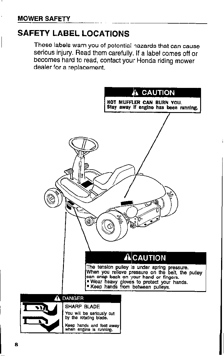
SAFETY LABEL LOCATIONS
These labels warn you of potential qazards that can cause
serious injury. Read them carefully. If a label comes off or
becomes hard to read, contact your Honda riding mower
dealer for a replacement.
HOT MUFFLER CAN BURN YOU.
Stay away If engine has been running.
I
You will be seriously cut
by the rotating blade.
Keep hands and feel away
Page 11
MOWER SAFETY
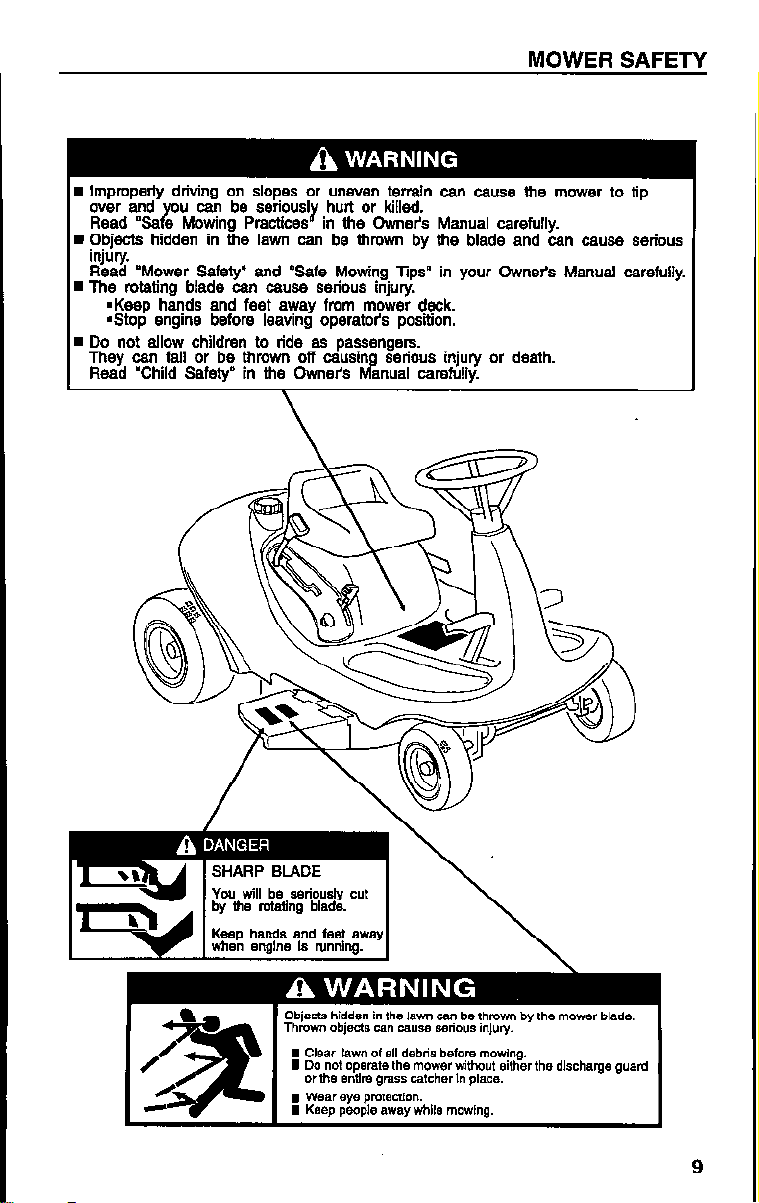
H Improperly drivtng on slopes or uneven terrain can cause the mower to tip
over and ou can be seriously hurt or killed.
Read “Sa e Mowing Practices in the Owner’s Manual carefully. Y
W Objects hidden in the lawn can be thrown by the blade and can cause serious
injury.
Read ‘Mower Safety” and “Safe Mowing Tips” in your Owne& Manual carefully.
n The rotating blade can cause serious injury.
n Keep hands and feet away from mower deck.
Gtop engine before leaving operator’s position.
n Do not allow children to ride as passengers.
They can fall or be thrown off causin serious injury or death.
Read “Child Safety” in the Owner%
fvf anual carefully.
Objects hidden in the lawn can be thmwn by the mower blade.
Thmwn objects can cause serious injury.
I Clear lawn of all debris before mowing.
I Do not operate the mower without either the discharge guard
or the entlre grass catcher In place.
I Wear eye pmtection.
I Keep people away while mowing.
9
Page 12
MOWER SAFETY
CHILD SAFETY: A MESSAGE =ro PARENTS
YOUR CHILD’S SAFETY IS VERY IMPORTANT to Honda.
Read this message if you decide to permit your youngster to
operate this riding lawn mower. Riding lawn mowers are
tools, not toys. As with any equipment, bad judgments can
result in serious injuries. You can help prevent accidents by
making good decisions about if, when, and how your
youngster operates this equipment.
The first question you’ll need to ask. is whether your
youngster is capable of operating this riding mower safely.
Remember, young people vary widely, and AGE IS NOT
THE ONLY FACTOR. Physically, a youngster must be
LARGE ENOUGH AND STRONG EiNOUGH to easily start
the riding mower and control its direction. The youngster
also needs enough size, strength, and coordination to
comfortably reach and operate the controls.
Another, tougher question you need to ask is if your
youngster has enough MATURITY AND RESPONSIBILITY
to safely operate this riding mower. Does the young person
think through problems and come to logical solutions? Be
honest! Anyone who takes unnecessary risks and doesn’t
obey rules should not operate this riding lawn mower.
If you decide that your son or daugh:er can handle the riding
mower safely, CAREFULLY READ THE OWNER’S MANUAL
with your youngster. Make sure you both understand all
instructions and safety information. Also, be sure your
youngster wears sturdy shoes and other protective clothing
when operating or handling the riding mower.
SUPERVISION is important. Walk behind your youngster
during the first few minutes of mowing. Even after the
youngster is confident, do not let them use the mower
without supervision. An adult should also be present during
refueling and maintenance. Be sure the riding mower is
properly maintained and kept in sa’!e operating condition.
By always placing safety first, your youngster will acquire
useful skills and a sense of accomplishment. And you’ll both
get the best results from your riding lawn mower.
10
Page 13
CONTROLS
This section helps you to identify the riding mower
controls, what they do, and how they work.
COMPONENT IDENTIFICATION
DESCRIPTION OF CONTROLS
Seat
Fuel Valve ...................
Ignition Switch .................
Height Adjustment Lever
Clutch Pedal
Brake Pedal
Shift Lever
Throttle
PTO Clutch Lever ...............
Parking Brake Lever ..............
Transmission Release Lever
......................
............
..................
..................
...................
.....................
........ 12
......... 14
..........
14
14
14
15
15
15
16
17
17
18
18
11
Page 14
CONTROLS
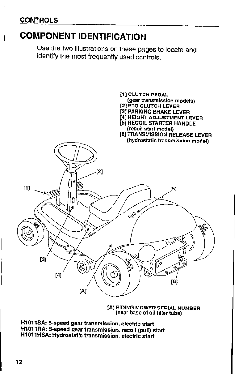
COMPONENT IDENTIFICATION
Use the two illusi:rations on these pages to locate and
identify the most frequently used controls.
[l] CLUTCH PEDAL
(gear transmission models)
[2] PTO CLUTCH LEVER
[3] PARKING BRAKE LEVER
[4] HEIGHT ADJUSTMENT LEVER
[5] RECOIL STARTER HANDLE
(recoil start model)
[S] TRANSMISSION RELEASE LEVER
(hydrostatic transmission model)
[A] RIDING MOWER SERIAL NUMBER
(near base of oil filler tube)
HlOll SA: !&speed gear transmission, electric start
HI01 1 RA: 5-speed gear transmission, recoil (pull) start
HlOllHSA: Hydrostatic transmission, electric start
12
Page 15
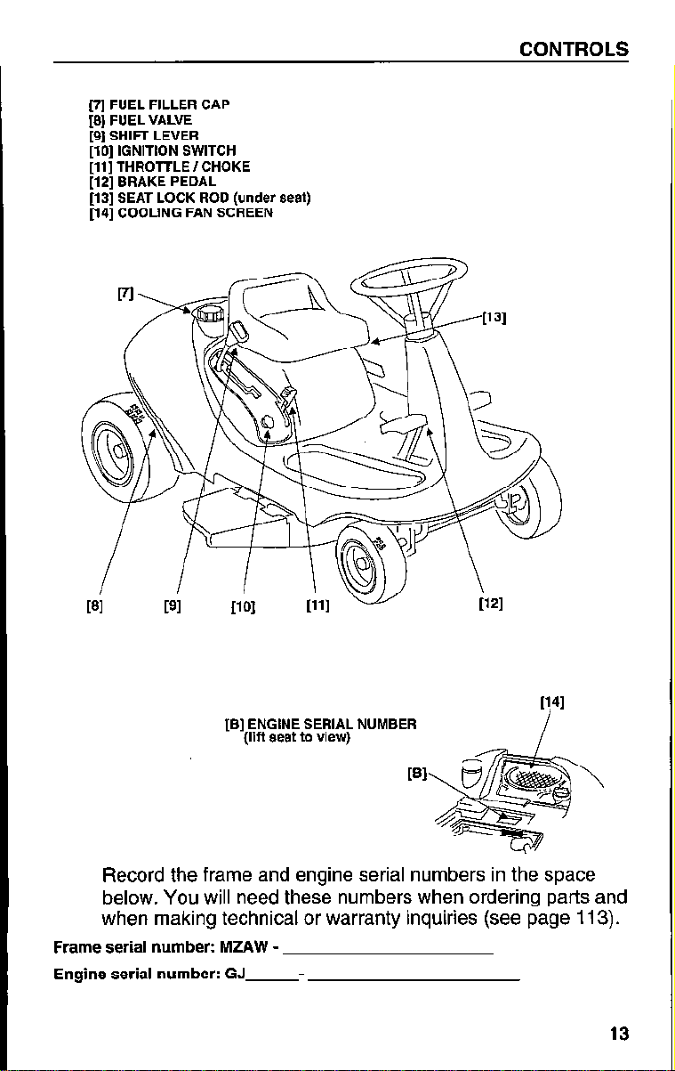
(7j FUEL FILLER CAP
[8] FUEL VALVE
[8] SHIFT LEVER
[lo] IGNITION SWITCH
[ll] THROlTLE / CHOKE
[12] BRAKE PEDAL
[13] SEAT LOCK ROD (under seat)
[14] COOLING FAN SCREEN
CONTROLS
[B] ENGINE SERIAL NUMBER
(lift seat to view)
PI
Record the frame and engine serial numbers in the space
below. You will need these numbers when ordering parts and
when making technical or warranty inquiries (see page 113).
Frame serial number: MZAW Engine serial number: GJ
-
13
Page 16
CONTROLS
DESCRIPTION OF CONTROLS
You will use these controls every tirne you operate the
riding mower. The Hl 011 riding mower uses colors to
identify control types. Orange levers and knobs are used to
control the movement of the riding mower. For example, the
parking brake lever and shift lever are color coded orange.
Yellow controls identify attachment controls, such as the
hand grip on the PTO clutch lever that is used to start and
stop blade movement. Black is used for component lift
controls (for example, deck height adjustment).
Seat
The seat can be adjusted back and forth for operator
comfort and tilted forward for battery access on electric start
models. Refer to page 53 for instructions.
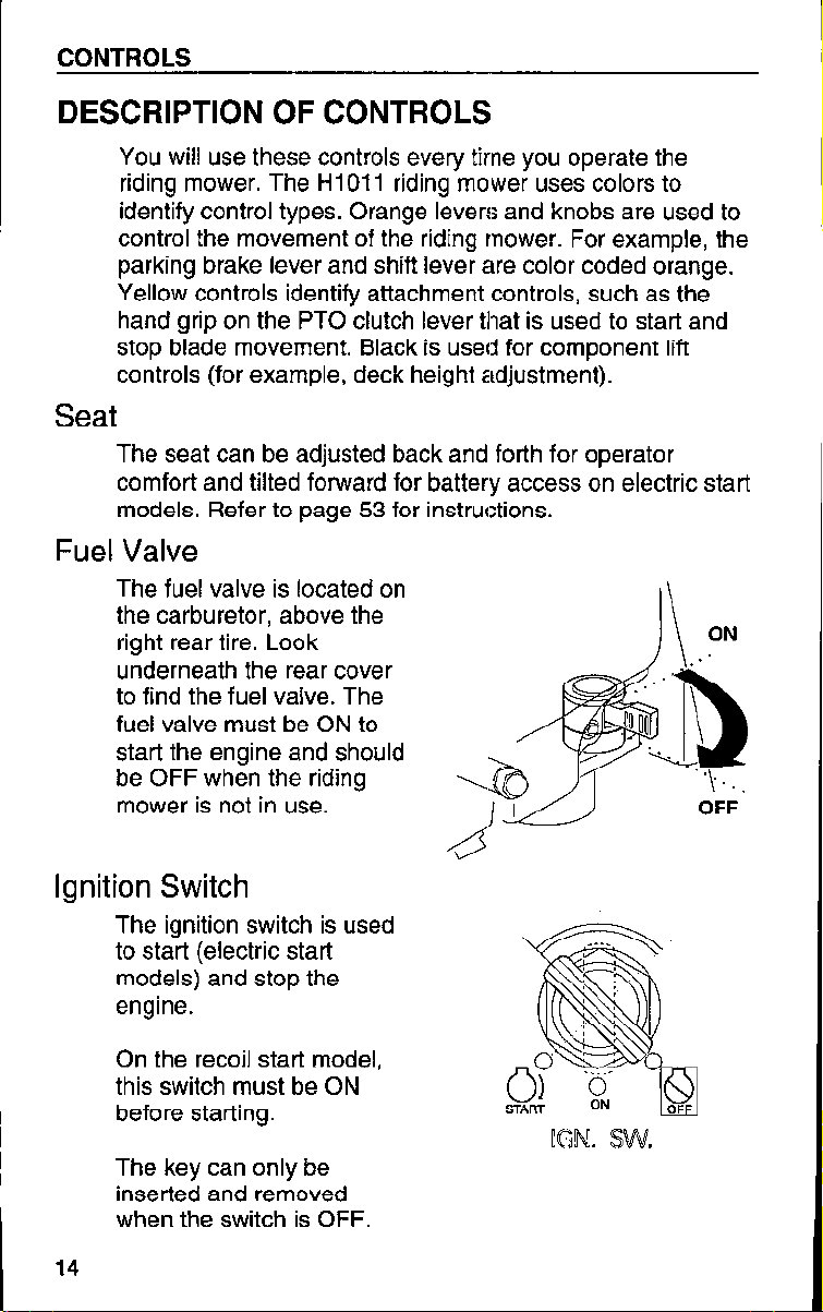
Fuel Valve
The fuel valve is located on
the carburetor, above the
right rear tire. Look
underneath the rear cover
to find the fuel valve. The
fuel valve must be ON to
start the engine and should
be OFF when the riding
mower is not in use.
ON
I\
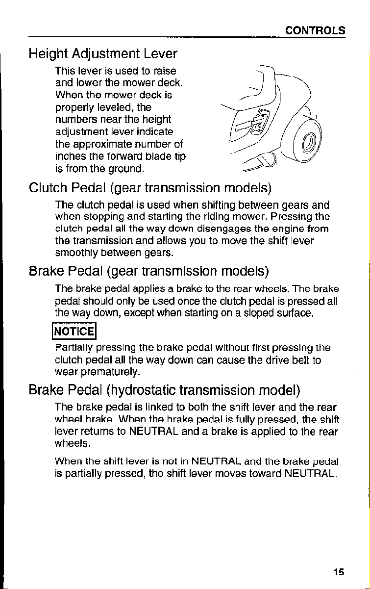
Ignition Switch
The ignition switch is used
to start (electric start
models) and stop the
engine.
On the recoil start model,
this switch must be ON
before starting.
The key can only be
inserted and removed
when the switch is OFF.
14
Page 17
Height Adjustment Lever
This lever is used to raise
and lower the mower deck.
When the mower deck is
properly leveled, the
numbers near the height
adjustment lever indicate
the approximate number of
inches the forward blade tip
is from the ground.
Clutch Pedal (gear transmission models)
The clutch pedal is used when shifting between gears and
when stopping and starting the riding mower. Pressing the
clutch pedal all the way down disengages the engine from
the transmission and allows you to move the shift lever
smoothly between gears.
Brake Pedal (gear transmission models)
The brake pedal applies a brake to the rear wheels. The brake
pedal should only be used once the clutch pedal is pressed all
the way down, except when starting on a sloped surface.
CONTROLS
lNoTlCEl
Partially pressing the brake pedal without first pressing the
clutch pedal all the way down can cause the drive belt to
wear prematurely.
Brake Pedal (hydrostatic transmission model)
The brake pedal is linked to both the shift lever and the rear
wheel brake. When the brake pedal is fully pressed, the shift
lever returns to NEUTRAL and a brake is applied to the rear
wheels.
When the shift lever is not in NEUTRAL and the brake pedal
is partially pressed, the shift lever moves toward NEUTRAL.
15
Page 18
CONTROLS
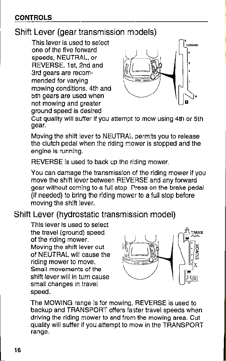
Shift Lever (gear transmission miDdels)
I
This lever is used to select
one of the five forward
speeds, NEUTRAL, or
REVERSE. lst, 2nd and
3rd gears are recommended for varying
mowing conditions. 4th and
5th gears are used when
not mowing and greater
ground speed is desired
Cut quality will suffer if you attempt to mow using 4th or 5th
gear.
Moving the shift lever to NEUTRAL permits you to release
the clutch pedal when the riding mower is stopped and the
engine is running.
REVERSE is used to back up the riding mower.
You can damage the transmission of the riding mower if you
move the shift lever between REVERSE and any forward
gear without coming to a full stop. F’ress on the brake pedal
(if needed) to bring the riding mower to a full stop before
moving the shift lever.
Shift Lever (hydrostatic transmission model)
This lever is used to select
the travel (ground) speed
of the riding mower.
Moving the shift lever out
of NEUTRAL wil! cause the
riding mower to move.
Small movements of the
shift lever will in turn cause
small changes in travel
speed.
The MOWING range is for mowing, REVERSE is used to
backup and TRANSPORT offers faster travel speeds when
driving the riding mower to and from the mowing area. Cut
quality will suffer if you attempt to mow in the TRANSPORT
range.
16
Page 19
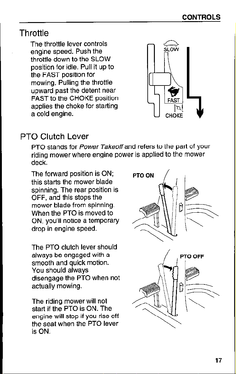
Throttle
The throttle lever controls
engine speed. Push the
throttle down to the SLOW
position for idle. Pull it up to
the FAST position for
mowing. Pulling the throttle
upward past the detent near
FAST to the CHOKE position
applies the choke for starting
a cold engine.
PTO Clutch Lever
PTO stands for Power Takeoffand refers to the part of your
riding mower where engine power is applied to the mower
deck.
CONTROLS
The forward position is ON;
this starts the mower blade
spinning. The rear position is
OFF, and this stops the
mower blade from spinning.
When the PTO is moved to
ON, you’ll notice a temporary
drop in engine speed.
The PTO clutch lever should
always be engaged with a
smooth and quick motion.
You should always
disengage the PTO when not
actually mowing.
The riding mower will not
start if the PTO is ON. The
engine will stop if you rise off
the seat when the PTO lever
is ON.
PTOON
/
/
, ,
PTO OFF
17
Page 20
CONTROLS
I
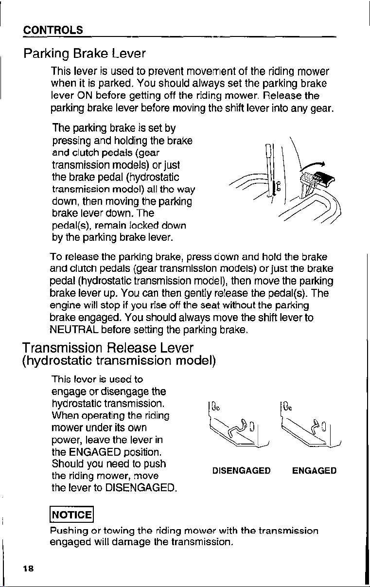
Parking Brake Lever
This lever is used to prevent movement of the riding mower
when it is parked. You should always set the parking brake
lever ON before getting off the riding mower. Release the
parking brake lever before moving the shift lever into any gear.
The parking brake is set by
pressing and holding the brake
and clutch pedals (gear
transmission models) or just
the brake pedal (hydrostatic
transmission model) all the way
down, then moving the parking
brake lever down. The
pedal(s), remain locked down
by the parking brake lever.
To release the parking brake, press down and hold the brake
and clutch pedals (gear transmission models) or just the brake
pedal (hydrostatic transmission model), then move the parking
brake lever up. You can then gently release the pedal(s). The
engine will stop if you rise off the seal without the parking
brake engaged. You should always move the shift lever to
NEUTRAL before setting the parking brake.
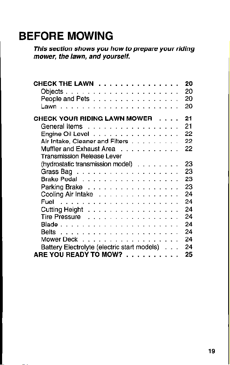
Transmission Release Lever
(hydrostatic transmission model)
This lever is used to
engage or disengage the
hydrostatic transmission.
When operating the riding
mower under its own
power, leave the lever in
the ENGAGED position.
Should you need to push
the riding mower, move
the lever to DISENGAGED.
INOTICE~
Pushing or towing the riding mower with the transmission
engaged will damage the transmission,
18
DISENGAGED ENGAGED
Page 21
BEFORE MOWING
This section shows you how to prepare your riding
mower, the /awn, and yourself.
CHECK THE LAWN
Objects .....................
People and Pets
Lawn
CHECK YOUR RIDING LAWN MOWER
General Items
Engine Oil Level
Air Intake, Cleaner and Filters
Muffler and Exhaust Area
Transmission Release Lever
(hydrostatic transmission model)
Grass Bag ...................
Brake Pedal
Parking Brake
Cooling Air Intake
Fuel
Cutting Height
Tire Pressure
Blade
Belts
Mower Deck ..................
Battery Electrolyte (electric start models)
ARE YOU READY TO MOW?
......................
......................
......................
......................
...............
................
.................
................
.........
...........
........
..................
.................
...............
.................
.................
..........
....
...
20
20
20
20
21
21
22
22
22
23
23
23
23
24
24
24
24
24
24
24
24
25
19
Page 22
BEFORE MOWING
CHECK YOUR LAWN
For your safety and the safety of others, always inspect the
area before mowing.
Objects
Anything which can be picked up by the blade and thrown is
a potential hazard to you and others. Look for things like
stones, sticks, bones, and wire, and remove them from the
mowing area.
People and Pets
People and animals near the mowing area can move into
your mowing path or into a position where they could be
struck by thrown objects. Clear the area of people,
especially children and pets. Their safety is your
responsibility.
Lawn
.Check the length and condition of the grass. Adjust your
mowing speed and cutting height accordingly.
Avoid mowing wet grass. Not only does mowing wet grass
result in poor cut quality, it also affords poor traction,
increasing the risk of loss of control of your riding mower.
20
Page 23
BEFORE MOWING
CHECK YOUR RIDING LAWN MOWER
For your safety and the service life of your equipment,
always inspect your riding mower before using it. Before
beginning your pre-operation checks, be sure:
l The riding mower is parked on a level surface.
l The PTO clutch lever is OFF and the shift lever is in
NEUTRAL.
l The ignition switch is OFF and the key is removed.
l The parking brake is ON.
General Items
Walk around the riding mower and check its general
condition. Look around and underneath it for signs of fluid
leaks.
Remove any excessive dirt and debris, especially around
the engine, mower deck, and moving components. Look for
signs of damage. Check nuts, bolts, screws, and pins for
tightness.
Keep all shields and covers in place while operating the
riding mower. If you find any problems, have them repaired
before mowing.
21
Page 24
BEFORE MOWING
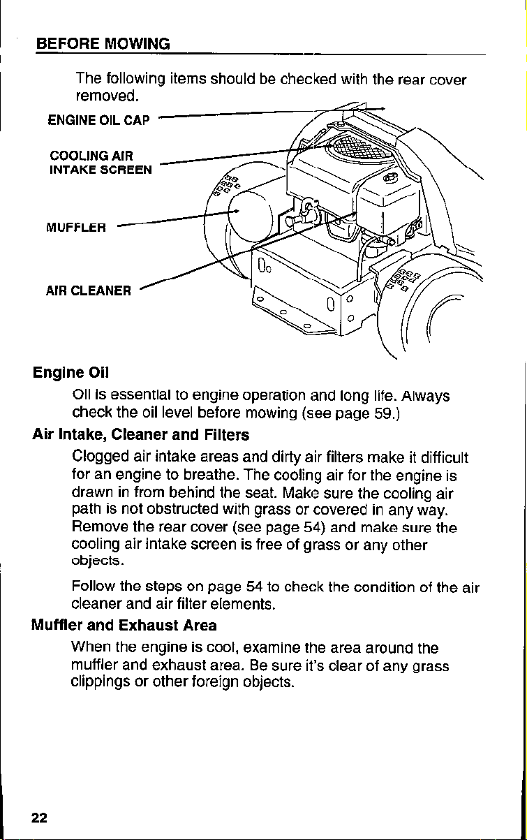
The following items should be checked with the rear cover
removed.
ENGINE OIL CAP
COOLING AIR
INTAKE SCREEN
MUFFLER
AIR CLEANER
Engine Oil
Oil is essential to engine operation and long life. Always
check the oil level before mowing (see page 59.)
Air Intake, Cleaner and Filters
Clogged air intake areas and dirty air filters make it difficult
for an engine to breathe. The cooling air for the engine is
drawn in from behind the seat. Make sure the cooling air
path is not obstructed with grass or covered in any way.
Remove the rear cover (see page 54) and make sure the
cooling air intake screen is free of grass or any other
objects.
Follow the steps on page 54 to check the condition of the air
cleaner and air filter elements.
Muffler and Exhaust Area
When the engine is cool, examine the area around the
muffler and exhaust area. Be sure it’s clear of any grass
clippings or other foreign objects.
22
Page 25
BEFORE MOWING
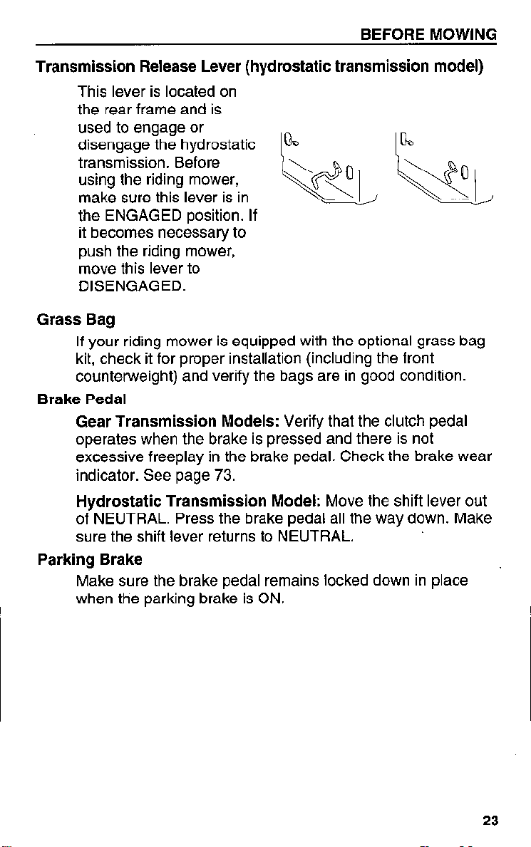
Transmission Release Lever (hydrostatic transmission model)
This lever is located on
the rear frame and is
used to engage or
disengage the hydrostatic
transmission. Before
using the riding mower,
make sure this lever is in
the ENGAGED position. If
it becomes necessary to
push the riding mower,
move this lever to
DISENGAGED.
Grass Bag
If your riding mower is equipped with the optional grass bag
kit, check it for proper installation (including the front
counterweight) and verify the bags are in good condition.
Brake Pedal
Gear Transmission Models: Verify that the clutch pedal
operates when the brake is pressed and there is not
excessive freeplay in the brake pedal. Check the brake wear
indicator. See page 73.
c&J
0
c
‘\\\I
L
Hydrostatic Transmission Model: Move the shift lever out
of NEUTRAL. Press the brake pedal all the way down. Make
sure the shift lever returns to NEUTRAL.
Parking Brake
Make sure the brake pedal remains locked down in place
when the parking brake is ON.
23
Page 26
BEFORE MOWING
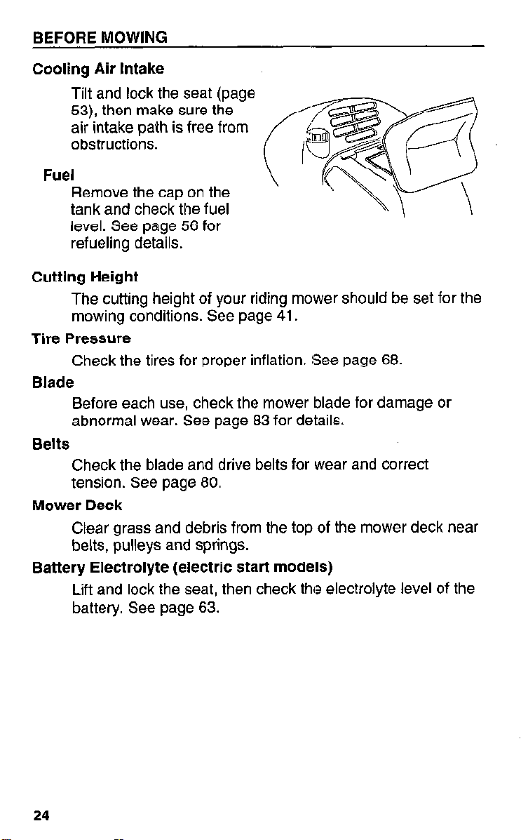
Cooling Air Intake
Tilt and lock the seat (page
53), then make sure the
air intake path is free from
obstructions.
Fuel
Remove the cap on the
tank and check the fuel
level. See page 56 for
refueling details.
Cutting Height
The cutting height of your riding mower should be set for the
mowing conditions. See page 41.
Tire Pressure
Check the tires for proper inflation. !See page 68.
Blade
Before each use, check the mower blade for damage or
abnormal wear. See page 83 for details.
Belts
Check the blade and drive belts for wear and correct
tension. See page 80.
Mower Deck
Clear grass and debris from the top of the mower deck near
belts, pulleys and springs.
Battery Electrolyte (electric start models)
Lift and lock the seat, then check the electrolyte level of the
battery. See page 63.
24
Page 27
BEFORE MOWING
ARE YOU READY TO MOW?
Your safety is your responsibility. A little time spent in
preparation will significantly reduce your risk.
Knowledge
Read and understand this manual. Know what the controls
do and how to operate them.
Familiarize yourself with the riding mower and its operation
before you begin mowing. Know what to do in case of
emergencies.
Clothing
Wearing protective clothing will reduce your risk of injury.
Long pants and eye protection reduce the risk of injuries
from thrown objects.
Sturdy shoes with aggressive soles will help protect your
feet and give you better traction on the pedals and platform
of the riding mower.
While the sound level of the riding mower is well within safe
limits, hearing protection will further protect your hearing.
25
Page 28

BEFORE MOWING
26
Page 29
OPERATING THE MOWER
This section tells you how to operate the riding mower
for safe and effective mowing.
MOWING PRECAUTIONS
Starting the Engine
Driving the Riding Mower
Mowing .................................
Braking .................................
Adjusting Speeds.
Stopping the Riding Mower
Safe Mowing Practices
Mowing Tips.
After Mowing
High Altitude Operation
.......................
........................ 34
....................
............................
............................ 43
....................
.................. 28
29
..................
................ 35
31
32
33
37
40
44
27
Page 30
OPERATING THE MOWER
MOWING PRECAUTIONS
Before operating the riding mower for the first time, please
review the IMPORTANT SAFETY INFORMATION
beginning on page 6 and the previous section, titled
BEFORE MOWING.
Even if you have operated other riding mowers, take time to
become familiar with how this riding mower works, and
practice in a safe area until you build up your skills.
Never tamper with, or alter any of the controls or safety
devices on the riding mower.
For your safety, avoid operating the engine in an enclosed
area such as a garage. Your riding mower’s exhaust
contains poisonous carbon monoxide gas which can collect
rapidly in an enclosed area and cause illness or death.
The Honda Hl 011 riding mower is easy to operate and
highly maneuverable. You need a complete understanding
of its operation and a certain amount of practice with its
controls to safely realize the full potential of this riding
mower.
Read this section completely before operating the riding
mower. Take time to familiarize yourself with the controls
and how they operate.
The small amount of time spent in familiarization will reward
you with greater efficiency and reduced risk.
28
Page 31

Starting the Engine
Start the engine outside in an
open area with good
ventilation.
1. Locate the fuel valve on the
carburetor, just above the
right rear tire. Move the fuel
valve to the ON position.
Pushing the fuel valve handle
toward the engine to ON
allows fuel to flow.
2. Make sure the PTO lever is
OFF (disengaged), the
parking brake is set ON, and
the shift lever is in NEUTRAL.
OPERATING THE MOWER
ON
I\
The engine will not start
unless these controls are
properly set.
3. To start a cold engine, move
the throttle lever to FAST,
then press the lever
outward, slightly past a
detent to CHOKE. To
restart a warm engine,
move the throttle lever to
the FAST position.
29
Page 32

OPERATING THE MOWER
4. (electric start) Insert the
ignition key into the
ignition switch. Turn the
key clockwise to START
and hold it there briefly
until the engine starts.
When it does, let the key
return to the ON position.
4a. (recoilstart) Insert the key
into the ignition switch and
turn it to ON. Grasp the
handle on the pull rope
and slowly pull until
resistance is felt, then pull
it briskly. Do not allow the
rope to snap back toward
the engine.
INOTICEI
(electric start models) Holding the ignition key in the START
position for more than five seconds may damage the starter.
5. If the engine fails to stat-t, wait at least ten seconds before
trying again. If you can’t get the engine to start after multiple
tries, refer to “Troubleshooting” on page 103.
6. After the engine has started,
slowly move the throttle
lever from CHOKE to a
point halfway between
SLOW and FAST while
the engine warms up.
UP
Once the engine has warn
you should keep the
throttle in the FAST
position while mowing.
This keeps the mower
blade spinning at the
proper speed (when the
PTO is ON) and provides
the best cut quality.
30
led,
Page 33

OPERATING THE MOWER
Do not use the throttle to adjust the riding mower ground
speed. Use the shift lever to select a different speed
instead. Slowing the riding mower’s ground speed with the
throttle causes the blade to spin slower, and cut quality will
suffer.
Driving the Riding Mower
Once the riding mower is moving forward, you’ll need to
know how to steer correctly, shift gears to adjust speed,
begin mowing, and how to stop.
Steering
To make it easier to cut various lawns, the HlOl 1 riding
mower is very maneuverable and can turn quickly.
Turning sharply when using higher
ground speeds can cause the riding
mower to lose traction.
The riding mower can tip over and you
can be injured or killed.
Avoid sharp turns when using higher
gears.
After using the riding mower for a while, you’ll get a better
feel for how much effort to use on the steering wheel for a
particular turn.
The speed of the riding mower greatly affects how the
steering responds. For this reason, you should shift the
transmission to a lower ground speed before entering sharp
turns.
Avoid turning the riding mower when operating on a sloped
surface. See “Mowing on Slopes” (page 38) for more details.
Selecting the Right Speed
Your Honda riding mower is equipped with a transmission
that offers multiple ground speeds. The shift lever is used to
select the appropriate ground speed for the task at hand.
31
Page 34

OPERATING THE MOWER
For the best cut quality, the engine should always be
operated with the throttle set in the FAST position. When
you need to speed up or slow down the riding mower, use
the shift lever (not the throttle) to change the ground speed.
Gear Transmission
.
MQ&&
: 1st - 3rd gears work best for
most mowing jobs. 4th and 5th gears should be used only
for transporting the mower (when the PTO is OFF) and are
not recommended for mowing.
Hydrostatic Transmission Model: Keep the shift lever in the
MOWING range. The TRANSPORT range should only be
used for transporting the mower (when the PTO is OFF)
and is not recommended for mowing.
On slopes or hills, use a slower shi,ft lever setting to
maintain a controllable, steady speed. Also, use slower
ground speeds under the following conditions:
l For sharp turns
l Mowing in narrow areas or near trees
l When edging or trimming near obstructions
l Cutting tall or very thick grass
REVERSE is used to back up the riding mower. Before
traveling in REVERSE, make sure the PTO is off and the
path is clear of people, pets and obstructions.
Mowing
When ready to begin mowing, approach the mowing area at
a reduced ground speed. Bring the riding mower to a full
stop, and check the position of the height adjustment lever.
You may have to make some trial cuts to determine which
setting is best for the lawn.
To begin mowing, make sure the throttle is set to FAST,
then move the PTO clutch lever to ON with a smooth, quick
motion. When you do, the blade starts to turn. To stop the
blade from turning, move the PTO to OFF.
piq
Do not operate the PTO clutch lever in an attempt to clear a
clogged mower deck. Doing so can damage the mower belt.
32
Page 35

OPERATING THE MOWER
See the “Mowing Tips” section later in this chapter for
details on getting the best cut possible from the riding
mower.
Braking (gear transmission models)
For best control, avoid stopping the riding mower on sloped
surfaces.
1. When approaching the area where you wish to stop,
smoothly press the clutch pedal all the way down and hold it
there. If necessary, press the brake pedal down, but only do
this when the clutch pedal is pressed first.
2. Once the riding mower has fully stopped, hold the clutch
and brake pedals down and move the shift lever to
NEUTRAL.
3. If this is an extended stop, set the parking brake ON, then
release the pedals.
p?iq
Partially pressing the brake pedal without first pressing the
clutch pedal can cause the drive belt to wear prematurely.
When using the brake pedal, press the brake pedal all the
way down and only when the clutch pedal is pressed first.
Braking (hydrostatic transmission model)
For best control, avoid stopping the riding mower on sloped
surfaces. The hydrostatic transmission on the HlOl 1 H
allows you two options for braking. You can either move the
shift lever or the brake pedal to slow down or stop the riding
mower.
Using the shift lever: To reduce the ground speed of the
riding mower, move the shift lever toward NEUTRAL.
Moving the shift lever fully into NEUTRAL will bring the
riding mower to a full stop as long as the ground is level. If
the riding mower is on a slope, you must press and hold the
brake pedal to completely stop the riding mower.
33
Page 36

OPERATING THE MOWER
Using the brake pedal: Partially pressing the brake pedal
causes the shift lever to move toward NEUTRAL. This
action causes the hydrostatic transmission to act as a
hydraulic brake and the riding mower slows down. Pressing
the brake pedal all the way down moves the shift lever fully
into the NEUTRAL position and applies a mechanical brake
to the rear wheels.
Adjusting Speeds (gear transmission models)
Always use the clutch pedal before moving the shift lever
between any forward gears. If shifting between any forward
gear and REVERSE, use the clutch and brake pedals to
bring the riding mower to a full and complete
Operating the shift lever on ;a sloped
surface can cause the riding mower to
lose traction.
The riding mower can tip over and you
can be killed or seriously injured.
stop.
Do not operate the shift lever while the
riding mower is on a sloped surface.
When shifting between forward speleds, always use the
clutch pedal and move to the next higher or lower gear. You
can start off from a complete stop when any gear is
selected.
Shifting From a Forward Gear to Another Forward Gear
1. Push the clutch pedal all the way down.
2. Move the shift lever to the desired gear position.
3. Gently release the clutch pedal.
4. You don’t need to bring the riding mower to a full stop if
shifting from one forward gear to another.
Shifting Between Any Forward Gear and Reverse
1. Press the clutch pedal all the way down, then press the
brake pedal all the way down to stop the riding mower.
2. Move the shift lever to the desired gear.
3. Gently release the brake pedal, then the clutch pedal.
34
Page 37

OPERATING THE MOWER
Adjusting Speeds (hydrostatic transmission
model)
The hydrostatic transmission in the Hl 011 H offers you an
infinitely variable range of speeds. This means you only
need to move the shift lever to change the ground speed
and to move in reverse.
Adjusting Forward Speed
1. To make the riding mower move faster when moving
forward, push the shift lever away from NEUTRAL.
2. To slow down, pull the shift lever back toward NEUTRAL.
Adjusting Reverse Speed
1. To make the riding mower move faster in REVERSE, pull
the shift lever away from NEUTRAL.
To slow down, push the shift lever toward NEUTRAL.
Stopping the Riding Mower
In an emergency:
1. Press the brake pedal all
the way down and hold it
there.
2. Turn the ignition switch to
OFF.
35
Page 38

OPERATING THE MOWER
3. Move the parking brake ON.
Normal Stop
(Gear transmission models) Use the clutch pedal first,
1.
then the brake pedal to stop the ridjng mower.
(Hydrostatic transmission model) Move the shift lever to
2.
NEUTRAL, then press and hold the brake pedal all the way
down.
Move the PTO lever to OFF.
3.
(Gear transmission models) Move the shift lever to
4.
NEUTRAL.
With the brake pedal pressed all the way down, press the
5.
parking brake ON.
Remove your foot from the brake pedal.
6.
7. Turn the ignition switch OFF.
Remove the ignition switch key.
8.
Turn the fuel valve OFF.
9.
Try to park on level ground. If you must park the riding
mower on a slope, block the wheels to prevent it from
rolling. Always remove the key when leaving the mower
unattended to prevent unauthorizecl use.
36
Page 39

OPERATING THE MOWER
Safe Mowing Practices
For your safety, keep all four wheels on the ground, and
avoid losing control of the riding mower.
Keep a firm grip on the steering wheel. Be very careful when
mowing uneven or rough ground.
Do not operate the riding mower near embankments, drop
offs or ditches. The riding mower could suddenly turn over if
a wheel is near the edge and it caves in or gives way.
Do not attempt to stabilize the riding mower by putting your
foot on the ground. Keep your feet on the platform and near
the pedals.
Take extra care when mowing near blind corners, shrubs,
trees or any other objects that may obscure your vision. If
you do strike an object, set the parking break, remove the
ignition key and inspect the riding mower for damage.
Repair any damage before any further operation.
The blades are sharp and spin at high
speed.
A spinning blade can cut you severely
and can amputate fingers and toes.
l Wear protective footwear.
l Keep your hands and feet away
from the mower deck while the
engine is running.
Stop the engine before performing any
adjustment, inspection, or maintenance.
37
Page 40

OPERATING THE MOWER
Mowing on Slopes
Never mow on a sloped surface greater than 10 degrees
(17% grade), since this can cause the riding mower to tip
over. Use a lower gear for better control and avoid sudden
stops or starts when on a sloped surface. If you are unsure
of the grade, obtain an inclinometer from a hardware store
to measure the area in question.
10 DEGREES
(17 % GRADE)
3
MAXIMUM
Always mow up and down a sloped surface, never across.
When mowing on slopes, empty the optional grass bags
when they are half full. Never operate the shift lever when
mowing on a sloped surface. Never mow a sloped surface
when the grass is wet. Avoid stopping on a sloped surface.
If it becomes necessary to stop on a sloped surface, use the
following special procedure when restarting the riding
mower.
Starting on a Sloped Surface
tim
Improper starting on sloped surfaces
can cause the riding mower to lose traction and tip over.
The riding mower can fall on you and
cause serious injury or death.
Use the following procedure if you must
start the riding mower on a sloped sur-
face.
!
Page 41

OPERATING THE MOWER
Gear Transmission Models:
1. Press the clutch pedal first, then the brake pedal and set the
parking brake ON. Move the shift lever to 1st gear.
2. Hold both pedals down and release the parking brake.
3. Slowly remove your foot from the clutch pedal, then from the
brake pedal.
Hydrostatic Transmission Model:
1. Press the brake pedal all the way down and hold it there.
2. Move the parking brake lever to OFF.
3. Slowly release the brake pedal while moving the shift lever
as required for a safe ground’speed.
Obstacles
Use the side of the mower deck to cut close to large
obstacles, such as fences or walls.
Be careful when mowing over obstacles embedded in the
lawn, such as sprinkler heads, paving, edging, etc. Avoid
anything that sticks up above the surface of the lawn.
If a blade hits something, or if any part of the riding mower
starts to vibrate, stop the engine immediately and check for
damage. Striking objects may damage a belt, blade, and/or
break the mower deck or other components. Vibration
usually indicates serious trouble.
A worn, cracked or damaged blade can
break, and pieces of the damaged
blade can become projectiles.
Thrown obiects can cause serious
injury. -
I
Inspect the blade regularly, and do not
operate the riding mower with a worn
1 or damaged blade.
The distributors limited warranty does not cover parts
damaged by accident or collision.
39
Page 42

OPERATING THE MOWER
Gravel and Loose Objects
Gravel, loose stones, and landscaping material can be
picked up by the riding mower and thrown many feet with
enough force to cause serious personal injury and/or
property damage. The best way to prevent potential injury
from thrown objects is to move the PTO lever to OFF prior
to reaching areas with gravel, loose stones, or landscaping
material.
Mowing Tips
In this section, you’ll learn some tips to getting a high quality
cut with your Honda riding mower.
General Tips
The mower blade must spin very fast for a good quality cut.
Keep the throttle in the FAST position when mowing. In
general, a slower ground speed produces a better quality
cut.
Try to maintain a constant travel speed when possible.
Changing speeds can produce an uneven finish.
Grass Condition
Mow when the grass is dry. Mowing wet grass does not
produce a neat finish. The inside of the mowing deck or
bagging chute may clog when mowing wet grass. Clumps of
wet grass will collect on the lawn and can create harmful
thatch.
A wet lawn reduces traction and braking performance of
your riding mower. Further, the tires may leave marks on
wet soil softened by moisture. This can detract from the
overall appearance.
How Often?
A well-groomed lawn requires mowing at short, regular
intervals. During the growing season, a lawn may require
mowing twice a week.
Page 43

OPERATING THE MOWER
Height of the Mower Deck
To adjust the height of the
mower‘deck, grip the
mower deck height
adjustment lever firmly,
then slightly lift to clear the
notches in the handle guide.
Move the lever outward from the riding mower and away
from the handle guide. Raise or lower the lever to the
desired position. Move the lever into the position notch and
allow the weight of the lever to lock it onto the handle guide.
The mowing deck can be positioned in a range of equally
spaced heights: 1.0, 1.5, 2.0, 2.5, 3.0 and 3.5. These
numbers indicate the approximate cutting height in inches.
To prevent possible damage to the mower deck, always
raise it fully (3.5) when driving the riding mower to and from
the mowing area; this provides maximum ground clearance.
To avoid damaging or disabling the mower deck height
adjustment lever, never attempt to move the lever when the
riding mower is moving.
A higher cut may be needed to protect the lawn during the
hotter summer months. Consult a local nursery or lawn and
garden center for advice about specific types of grasses and
growing conditions in your area.
Most grasses should be cut when they have grown l/2 to 1
inch above the recommended height. If your grass grows
too tall, cut it back a little at a time, allowing a few days for
the grass to recover between mowings. Avoid cutting more
than one third of the total grass height in any one mowing.
41
Page 44

OPERATING THE MOWER
Mowing Patterns
The mowing pattern you use on the lawn can greatly affect
the overall quality of the finished cut.
Side-Discharge Mowing
Start mowing from the outside edge of the mowing area and
work toward the center. Avoid mowing patterns that cause
clippings to be discharged onto uncut grass and cause
clumping. Typically, a counterclockwise pattern is a good
choice and provides a smooth, even finish. However, you
may wish to alter the pattern to prevent clippings from
accumulating in areas such as a nearby patio or driveway.
Overlapping Your Path
Allow an adequate amount
of overlap in the cutting
path when mowing. Four to
six inches is
recommended; this is
roughly the same width as
a front tire.
When overlapping in a
curve, shift to a lower
speed and overlap the
previous cut by 50%, or
approximately half the
width of the mower deck. In
extremely tall or thick
grass, you may have to cut
a larger overlap.
OVERLAP
If Cut Quality is Poor
If you experience poor cut quality, check the following items:
l Air pressure in tires
l Condition of blade
42
50%
Page 45

OPERATING THE MOWER
l Mower deck height and leveling
l Correct ground speed for lawn conditions
l Engine throttle in FAST position
0 Sufficient overlap
l Mowing deck is clear of grass or other obstructions
Adjustments to Improve Cut Quality
Blade
Verify the blade is leveled per the instructions in the
“Maintenance and Adjustments” chapter.
Make sure the blade is in good condition and has a properly
sharpened edge. See page 83 for details.
Cutting height
Make sure the cutting height adjustment lever is properly
set. See page 41.
Tires
Underinflated tires can cause uneven mowing or allow the
mower deck to cut lower than indicated on the cutting height
adjustment lever. Overinflated tires produce a harsher, less
comfortable ride and can also damage the grass and tires.
See page 68.
After Mowing
Always take a few moments to inspect the riding mower
when you’ve finished mowing. A few simple steps done now
can greatly prolong the life of your riding mower and make it
easier to use the next time.
Under most conditions, the riding mower accumulates
clippings, mud, dirt and other debris on the mower deck and
other areas. Frequently, such debris contains moisture and
if allowed to remain on the mower frame, mower deck or
other metal parts, rust can form. Regular cleaning not only
helps prevent such rusting, but also makes the riding mower
operate better. Also, it is much easier to clean these parts
when the debris or clippings are fresh rather than stuck on
the riding mower for days or weeks at a time.
43
Page 46

OPERATING THE MOWER
Mower Deck Cleaning
After each use, allow the engine and exhaust areas to cool.
Inspect, then clear and clean the mower deck of debris. A
good spraying of water can clear most clippings, dirt and
mud.
Wash the mower deck only when the riding mower is cool.
The bearings on the blade pulley shaft expand as they heat
up. Cooling rapidly with water can allow moisture to be
trapped inside the bearings. This can cause rust to form on
the bearing surfaces and shorten bearing life.
Clean both the top and bottom of the mower deck and also
the area around the discharge chute. Operate the engine
and mower for a few minutes after washing to dry moving
parts.
Cleaning Other Areas
Certain parts other than the mower deck can accumulate
clippings and other debris. When the riding’mower is cool,
you should inspect these areas and brush or wipe off any
debris with a soft brush or slightly damp rag. Specifically,
remove the rear cover and look around the top of the
engine, exhaust area and muffler and by the rear axle near
the frame. Do not spray water directly on the engine.
Check and clean (if needed) the footwells, lower and upper
chutes (when the optional grass balg kit is used), engine
cooling fan screen and air intake path behind the seat.
High Altitude Operation
At high altitude, the standard carburetor air-fuel mixture will
be too rich. Performance will decrease, and fuel
consumption will increase. A very rich mixture will also foul
the spark plug and cause hard starting.
High altitude performance can be improved by installing a
smaller diameter main fuel jet in the carburetor. If you
always operate the mower at altitudes higher than 1,800
meters (6,000 feet) above sea level, have an authorized
Honda riding mower dealer perform this carburetor
modification.
44
Page 47

OPERATING THE MOWER
Even with carburetor modification, engine horsepower will
decrease about 3.5% for each 300 meter (1,000 foot )
increase in altitude. The effect of altitude on horsepower will
be greater than this if no carburetor modification is made. A
reduction in engine horsepower will reduce mowing
performance.
When the carburetor is modified for high altitude operation,
the air-fuel mixture will be too lean for low altitude use.
INOTICEI
Operation at altitudes below 1,800 meters (6,000 feet), with
high altitude carburetor modifications, may cause the engine
to overheat and result in serious engine damage.
For low altitude use, reinstall the standard main fuel jet.
45
Page 48

OPERATING THE MOWER
Page 49

MAINTENANCE & ADJUSTMENTS
This section tells you how to perform normal
maintenance and adjustments.
Importance of Maintenance
Emission Control System
Maintenance Schedule .............
Seat .......................
Rear Cover.
Air Cleaner
Fuel.
Engine Oil
Spark Plug
Battery Service (electric start model)
Fuse Replacement (electric start model)
Clutch Pedal Freeplay .............
Tires and Wheels ................
PTO Lever Freeplay ...............
Brake Maintenance ...............
.......................
...................
....................
.................... 59
....................
.......... 48
........... 50
.....
... 65
52
53
54
54
56
62
63
67
68
70
71
Mower Deck
Blade Belt
Blade Maintenance ...............
Spark Arrester Maintenance
Drive Belt Replacement .............
Lubrication Points ............... 93
Carburetor
...................
.....................
.........
....................
73
80
83
89
90
94
47
Page 50

THE IMPORTANCE OF MAINTENANCE
Good maintenance is essential for safe, economical, and
trouble free operation. It will also help reduce air pollution.
Improper maintenance, or failure to correct a problem before operation, can
cause a malfunction in which you can
be seriously hurt or killed.
Always follow the inspection and maintenance recommendations and schedules in this owner’s
To help you properly care for your riding mower, the
following pages include a maintenance schedule, routine
inspection procedures, and simple maintenance procedures
using basic hand tools. Other service tasks that are more
difficult, or require special tools, are best handled by
professionals and are normally performed by a Honda
technician or other qualified mechanic.
The maintenance schedule applies to normal operating
conditions. If you operate your riding mower under unusual
conditions, consult you servicing dealer for
recommendations applicable to your individual needs and
use.
manual.
Remember that your servicing dealer knows your riding
mower best and is fully equipped to maintain and repair it.
To ensure the best quality and reliability, use only new,
genuine Honda parts or their equivalents for repair and
replacement.
Maintenance, replacement, or repair of the emission
control devices and systems may be performed by any
engine repair establishment or individual, using parts
that are “certified” to EPA standalrds.
48
Page 51

MAINTENANCE 81 ADJUSTMENTS
Maintenance Safety
Some of the most important safety precautions follow.
However, we can not warn you of every conceivable hazard
that can arise while performing maintenance. Only you can
decide whether or not you should perform a given task.
Failure to properly follow maintenance
instructions and precautions can cause
you to be seriously hurt or killed.
Always follow the procedures and pre-
/ cautions in the owner’s manual. /
Safety Precautions
Make sure the engine is off before you begin any
maintenance or repairs. This will eliminate several potential
hazards:
- Carbon monoxide poisoning from engine exhaust.
Be sure there is adequate ventilation whenever you
operate the engine.
- Burns from hot parts.
Let the engine and exhaust system cool before touching.
- Injury from moving parts.
Do not run the engine unless instructed to do so.
Read the instructions before you begin, and make sure you
have the tools and skills required.
To reduce the possibility of fire or explosion, be careful when
working around gasoline. Use only nonflammable solvent, not
gasoline to clean parts. Keep cigarettes, sparks, and flames
away from all fuel-related parts.
For certain operations, the riding mower must be raised off the
ground. Be sure the riding mower is solidly supported before
you put any part of your body under the riding mower.
49
Page 52

MAINTENANCE & ADJUSTMENTS
l Disconnect the spark plug cap and wear heavy gloves
when working near the mower deck, belts, or blades.
l Never support or stand the riding mower on either side
or end. Fuel, oil, or battery electrolyte can leak out.
EMISSION CONTROL SYSTIEMI
Source of Emissions
The combustion process produces carbon monoxide, oxides
of nitrogen, and hydrocarbons. Control of hydrocarbons and
oxides of nitrogen is very important because, under certain
conditions, they react to form photochemical smog when
subjected to sunlight. Carbon monoxide does not react the
same way, but it is toxic.
Honda utilizes lean carburetor settings and other systems to
reduce the emissions of carbon monoxide, oxides of nitrogen,
and hydrocarbons.
The U.S. and California Clean Air Acts
EPA and California regulations require all manufacturers to
furnish written instruction describing the operation and
maintenance of emission control systems.
The following instructions and procedures must be followed to
keep the Honda engine emissions within the emission
standards.
Tampering and Altering
Tampering with or altering the emission control system may
increase emissions beyond the legal limit. Among those acts
that constitute tampering are:
l Removal or alteration of any part of the intake, fuel, or
exhaust systems.
l Altering or defeating the governor linkage or
speed-adjusting mechanism to cause the engine to
operate outside its design parameters.
50
Page 53

MAINTENANCE 81 ADJUSTMENTS
Problems That May Affect Emissions
If you are aware of any of the following symptoms, have your
engine inspected and repaired by your authorized Honda
servicing dealer.
l Hard starting or stalling after starting.
l Rough idle.
l Misfiring or backfiring under load.
l Afterburning (backfiring).
l Black exhaust smoke or high fuel consumption.
Replacement Parts
The emission control systems on your new Honda engine were
designed, built, and certified to conform with EPA and California
emission regulations. We recommend the use of genuine Honda
parts whenever you have maintenance done. These
original-design replacement parts are manufactured to the same
standards as the original parts, so you can be confident of their
performance. The use of replacement parts that are not of the
original design and quality may impair the effectiveness of your
emission control system.
A manufacturer of an aftermarket part assumes the responsibility
that the part will not adversely affect emission performance. The
manufacturer or rebuilder of the part must certify that the use of
the part will not result in a failure of the engine to comply with
emission regulations.
Maintenance
Follow the Maintenance Schedule on page 52. Remember that
this schedule is based on the assumption that your machine will
be used for its designed purpose. Sustained high-load or
high-temperature operation, or use in unusually wet or dusty
conditions, will require more frequent service.
51
Page 54

MAINTENANCE 81 ADJUSTMENTS
Maintenance Schedule
l Whichever comes first.
6 Service the air cleaner more frequently when used in dusty areas.
i These items should be serviced by an authorized Honda riding mower dealer, unless the
owner has proper tools and is mechanically proficient. See the Shop Manual for the HlOll.
’ This interval for first service only
*This interval for second and future service
52
Page 55

MAINTENANCE & ADJUSTMENTS
Seat
To access the battery compartment or to adjust the seat
position, you must raise and lock the seat.
Raising and Locking the Seat
1. On the left side of the riding mower, just below the seat
cushion, there is a spring loaded, U-shaped pin used to lock
the seat in either a raised or lowered position. Pull the pin
outward and away from the seat, then raise the seat up.
2. With the seat in the fully
raised position, allow the
pin to slide back toward the
seat bracket to lock it in the
up position.
3. Verify the seat is locked in
the upright position by
pressing down on the seat.
Adjusting the Seat Position
1. Locate and loosen (don’t
remove) the four hex bolts
used to attach the seat to
the seat bracket.
2. Move the seat back and forth to obtain the desired position.
3. Securely tighten the four hex bolts, then lower and lock the
seat.
Lowering and Locking the Seat
1. To lower the seat, slightly move the seat upward, to take
pressure off the locking pin.
2. While grasping the seat with one hand, use your other hand
to pull the locking pin away from the seat bracket.
3. Lower the seat all the way down, then release the locking
pin, so it locks into the hole on the side of the seat bracket.
Verify that the seat is locked down by trying to lift the seat.
53
Page 56

MAINTENANCE & ADJUSTMENTS
Rear Cover
The rear cover must be removed to perform some
maintenance procedures. It must also be removed prior to
transporting the riding mower.
To Remove the Rear Cover
1. Stand behind the riding
mower and grasp the
edge underneath the rear
cover.
2. Pull upward, then lift the rear
cover away from the riding
mower.
To Reattach the Rear Cover
1. There are square tabs molded into the front edge of the rear
cover, near the air intake area. Insert these tabs into the
riding mower rear body, just behind the seat.
2. Lower the rear cover so the rounded edge aligns with the
clips in the rear body.
3. The two posts on the lower edges of the rear cover should
be carefully pressed into the rubber grommets on the rear
body.
Air Clearier
Check that the air cleaner elements are clean and in good
condition. A dirty air cleaner assembly restricts air flow to
the engine, reducing performance. A damaged element
allows dirt to enter the engine, causing rapid engine wear.
1.
Remove the rear cover. As you face the rear part of the
exposed engine, the air cleaner is located on the right rear
side of the engine. Remove the wing nut from the top of the
air cleaner housing cover.
2.
The air cleaner assembly has two parts. The outer foam
section covers the paper element and can be removed.
54
Page 57

MAINTENANCE & ADJUSTMENTS
WING NUT
COVER y
FOAM. ELEMENT
PAPER ELEMENT
RUBBER SEAL
If the foam element appears clean over more than half its
3.
--
surface, it does not need cleaning. Reinstall the air cleaner
housing cover. If the foam element appears dirty, continue
to the next step.
[NOTICEI
Operating the engine without the air cleaner or with
damaged elements can cause rapid engine wear.
Remove the air cleaner assembly. Separate the foam
4.
element from the paper element, and carefully check for
holes or tears. Replace any damaged element(s).
Clean the foam element by squeezing it in warm soapy
5.
water, rinsing it, and allowing it to dry. You may also use a
nonflammable solvent and then allow it to dry.
Oil the foam element by dipping it in clean engine oil and
6.
squeezing out all excess oil. If too much oil is left in the
foam, the engine may smoke when started.
Clean the paper element by tapping it on a hard surface to
7.
knock off dirt or by blowing compressed air (at less than 30
psi) through the element from the inside. Never try to brush
off the dirt
Use a damp rag to wipe any dirt from the inside of the air
a.
- that just forces it into the paper filter fibers.
cleaner housing and cover. Be careful not to allow dirt into
the duct leading to the carburetor. Be sure the rubber seal
in the base is in place and in good condition.
55
Page 58

MAINTENANCE bh ADJUSTMENTS
9. Place the foam element over the paper element, and install
them back onto the air cleaner housing.
10. Reinstall the air cleaner housing cover and wing nut.
Fuel
Fuel tank capacity: 3.4 t(O.9 US gal)
Pump octane rating: 86
Refueling
Remove the cap on the
tank and check the fuel
level. Refuel carefully to
avoid overfilling or spilling
fuel. Just inside the filler
neck is a maximum fill
marker. Do not fill past this
marker.
piE/
Fuel can damage paint and plastic. Be careful not to spill
fuel when filling the fuel tank. Damage caused by spilled
fuel is not covered under warranty.
MAXIMUM FILL MARK
Gasoline is highly flammable and explosive, and you can be burned or seriously injured when refueling.
l Stop engine and keep heat, sparks,
and flame away.
l Refuel only outdoors.
l Wipe up spills immediately.
Never refuel the riding mower inside a building where fumes
may reach an open flame or spark. Keep gasoline away
from appliance pilot lights, electric motors, etc.
Refuel in a well ventilated area before starting the engine. If
the engine has been running, allow it to cool. Avoid
overfilling the tank or spilling fuel.
56
Page 59

MAINTENANCE & ADJUSTMENTS
Spilled fuel not only creates a fire hazard, it can cause
environmental damage. Wipe up spills immediately. Dispose
of gasoline properly.
Fuel Recommendation
Honda recommends unleaded fuel (86 pump octane)
because it produces fewer engine and spark plug deposits
and extends exhaust system life.
Be sure the gasoline you use is as fresh as possible. Stale
or contaminated gasoline or an oil/gasoline mixture can
damage the engine or its fuel system. Avojd getting dirt or
water in the fuel tank.
When the engine speed drops under heavy loads, you may
hear light “spark knock” or “pinging” (a metallic rapping
noise). This is no cause for concern.
However, if this spark knock or pinging occurs at a steady
engine speed, under a normal load, the engine can be
damaged. Try using fresh gasoline in the tank or change
brands of gasoline. If spark knock or pinging persists,
contact your authorized Honda riding mower dealer.
Running the engine with persistent spark knock or pinging
can cause engine damage. This type of damage is not
covered by the Distributor’s Limited Warranty.
57
Page 60

MAINTENANCE & ADJUSTMENTS
Fuel Filter Replacement
We suggest you perform this procedure when the fuel tank
is nearly empty.
1.
Remove the rear cover and
move the fuel valve to ON
(page 14). Locate the
carburetor near the lower
right side of the engine.
There are two bolts on the
round carburetor bowl.
The angled screw is used
for fuel draining, while the
other is to remove the
bowl itself.
2.
Drain any remaining fuel
from the riding mower into
an approved container by
removing the angled
carburetor drain bolt.
Locate the fuel supply line
3.
between the carburetor
and fuel tank. Loosen the
hose clamp where the fuel
supply line connects to the
fuel tank and disconnect
the fuel line from the tank.
4.
The fuel filter is a white plastic piece inside the fuel line. The
filter partially sticks out of the fuel line. Note how the fuel
filter is installed when you remove it from the fuel line.
Install a new fuel filter into the fuel line.
5.
Dispose of the old filter and any spilled fuel properly.
6.
58
Page 61

MAINTENANCE & ADJUSTMENTS
Engine Oil
Engine Oil Capacity: 1 .Ic (1.16 US quarts)
Checking the Level
1. Remove the rear cover.
2. The oil filler cap is located
on the left side of the
engine.
Clean the area around the
oil filler cap, unscrew it,
and wipe the dipstick with
a clean cloth.
3. Insert the dipstick as shown
here (don’t screw it back in).
4. If the oil level is low (near
the bottom), add enough
oil to bring the level to the
upper mark. Recheck the
oil level after adding any
new oil.
5. If the oil level is close to the
upper mark, no additional oil
is needed. Replace the dipstick
and screw it back in securely.
Do not overfill.
Running the engine at a low oil level or with no oil causes
engine damage.
PPER
OWER
59
Page 62

MAINTENANCE & ADJUSTMENTS
Engine Oil Recommendations
Oil is a major factor affecting performance and service life.
Use 4-stroke automotive detergent oil.
SAE low-30 is recommended for general use. Other
viscosities shown in the chart may be used when the
average temperature in your area is within the
recommended range.
The SAE oil viscosity and service classification are in the
API label on the oil container. Honda recommends that you
use API SERVICE category SH or SJ oil with the API
certification mark displayed on the container.
60
Page 63

MAINTENANCE & ADJUSTMENTS
Changing the Oil
Change the oil at the recommended interval (page 52) or
more frequently under extreme operating conditions.
Drain the oil while the engine is warm to assure rapid and
complete draining.
1.
Remove the rear cover.
Clean the area around the oil filler cap and unscrew it.
2.
Near the bottom of the oil filler tube is the oil drain petcock
3.
and drain tube fitting. Attach the supplied tubing to the drain
fitting. Position the other end of the tubing in a suitable oil
collection container that can hold at least 2.2 L (2 US quarts).
4.
Using a 10 mm wrench,
open, but do not remove,
the petcock valve.
5.
Once the used oil has drained, close the petcock valve and
seat it lightly. Do not over tighten. Remove the drain tube
and wipe it clean.
Fill the engine with the correct amount of the recommended oil
6.
through the oil filler tube. Do not overfill; measure the oil
level as shown on page 60.
7.
Start and operate the engine for a few minutes, then recheck the
oil level and adjust if necessary. Verify there is no oil leaking
from the oil filler tube, petcock, or drain tube fitting areas.
Please dispose of used motor oil and the oil containers in a
manner that is compatible with the environment. We
suggest you take it in a sealed container to your local
recycling center or service station for reclamation. Do not
throw it in the trash or pour it on the ground.
61
Page 64

MAINTENANCE & ADJUSTMENTS
Spark Plug
Recommended Types
NGK: BPR5ES ND: WI GEPR-U
INOTICE~
Spark plugs of the wrong size or inczorrect heat range can
cause engine damage.
Spark Plug Removal, Inspection and Replacement
For good performance, the spark plug should have the
correct gap and be free of deposits.
1.
Remove the rear cover, then disconnect the spark plug cap
and remove any dirt from around the spark plug area.
2.
Remove the spark plug.
3.
Inspect the spark plug for
excessively worn
electrodes, chips or
cracks in the insulator, or
excessive deposits.
Replace the spark plug if
you have any doubts
about its condition.
4.
Measure the electrode gap
with a wire gap gauge.
Adjust the gap to 0.7 - 0.8
mm (0.028 - 0.031 inch)
by bending the side
electrode with a proper
spark plug tool.
0.7 -- 0.8 mm
(0.0:28 - 0 .031 inch)
62
Page 65

MAINTENANCE & ADJUSTMENTS
5. Install the spark plug
carefully, by hand, to
avoid cross threading of
the cylinder head.
Use a spark plug wrench
to tighten the plug enough
to compress the washer.
For a used plug, tighten
l/8 to l/4 of a turn after
the spark plug seats. For
a new plug, tighten l/2
turn after the spark plug
seats.
A loose spark plug can become hot enough to damage the
engine. Overtightening a spark plug can damage the threads
in the engine.
6. Reconnect the spark plug cap.
Battery Service (electric start models)
The riding mower charging system charges the battery while
the engine is running. However, if the riding mower is only
used periodically, the battery must be charged monthly to
maintain the battery service life.
A lead-acid battery self-discharges at a rate of 0.5 - 1 .O %
per day. If the riding mower is not operated for a month, the
battery can discharge as much as 30%. This could cause
the engine not to start or shorten the service life of the
battery. To charge the battery, follow the procedures below.
Removal
1. Raise and lock the seat (see page 53).
2. Remove the negative (-) cable from the battery negative (-)
terminal; then remove the positive (+) cable from the battery
positive (+) terminal.
3. Remove the battery from the battery tray.
63
Page 66

MAINTENANCE & ADJUSTMENTS
Inspection
1. Remove the battery cell caps.
2. Inspect the electrolyte level of each cell. The electrolyte
level must be maintained between the upper and lower level
indicators.
3. If the electrolyte level is below the lower indicator, add
distilled water as necessary.
Emergency Procedures
Eyes - Flush with water from as cup or other container for
at least fifteen minutes. (Water uncler pressure can damage
the eye.) Immediately call 911 (USA only) or a physician
immediately.
Skin - Remove contaminated clothing. Flush the skin with
large quantities of water. Call a physician immediately.
Swallowing -
Control Center (USA only) or a physician immediately.
The battery contains sulfuric acid (electrolyte) which is highly corrosive and
poisonous.
Getting electrolyte in your eyes or on
your skin can cause serious burns.
Wear protective clothing and eye pro-
tection when working near the battery.
The battery is rated at 14Ah (ampere-hours). 10% of the
ampere-hour rating should be used as the charging current.
A battery charger should be used that can be adjusted to
deliver 1.4 amperes.
Drink water or milk. Call your local Poison
64
Page 67

The battery gives off explosive hydro-
gen gas during normal operation.
A spark or flame can cause the battery
to explode with enough force to kill or
seriously hurt you.
Wear protective clothing and a face
shield, or have a skilled mechanic do
the battery maintenance.
Charging the Battery
1. Remove the battery cell caps.
2. Connect the battery charger following the manufacturer’s
instructions, then charge the battery 3-4 hours.
3. After the battery is charged, inspect the electrolyte level in
each of the cells. Add distilled water as necessary, then
install the battery caps.
4. Clean the outside of the battery and the battery
compartment with a solution of baking soda and water.
Don’t allow any of the solution to drip down the vent caps
into the battery cells.
Installation
1. With the seat raised and locked, install the battery into the
riding mower. The battery terminals should face the rear.
2. Install the positive (+) cable onto the battery positive (+)
terminal; then install the negative (-) cable onto the battery
negative (-) terminal, then lower and lock the seat.
Fuse Replacement (electric start models)
The fuse and fuse holder are next to the positive (+)
connector near the battery. The riding mower will not start if
the fuse is blown. To replace the fuse:
65
Page 68

MAINTENANCE & ADJUSTMENTS
Turn the ignition switch to OFF, then raise and lock the seat.
1.
See page 53.
The fuse used in the riding mower is a blade type. Grip the
2.
edge of the fuse with one hand and the fuse holder with the
other. Pull the fuse straight out of the holder.
A blown fuse is indicated
by a broken link, visible
between the two blades on
~
the fuse. Discard a blown
fuse and replace it with one
of the same value.
I
If fuse failure occurs, determine the cause and correct the
problem before operating the riding mower further.
p?iEq
Never use a fuse with a different ra.ting from that specified.
Serious damage to the electrical system or fire may result.
Page 69

MAINTENANCE & ADJUSTMENTS
Clutch Pedal Freeplay (gear transmission models)
Gear transmission models use a tensioner arm clutch and
the only adjustment is the freeplay in the clutch pedal.
Inspection
1. Place a ruler flat, so it is up
against the clutch pedal arm.
Move the clutch pedal and
2.
measure arm movement
until resistance is felt.
Freeplay distance should be
3.
between 25 - 27.5 mm
(1 - l-1/16 inch). You
should adjust the freeplay
when it reaches 17 mm
(1 l/16 inch).
Adjustment
1. Lower the mower deck all the way down.
2. From the right side, look between the riding mower frame and
the mower deck. Locate the clutch arm turnbuckle and lock
nuts. The clutch arm runs along the inner left hand side of
the riding mower frame.
3. The forward locking nut on the clutch arm turnbuckle is a
standard right hand thread. The rear locking nut is a left
hand thread. There are flat spots on the side of the
turnbuckle for a 12 mm wrench.
4. To decrease freeplay,
loosen both locknuts and
turn the turnbuckle to
shorten clutch rod.
\
I
67
Page 70

MAINTENANCE & ADJUSTMENTS
5. To increase freeplay, loosen both the locknuts and turn the
turnbuckle to lengthen the clutch rod.
6. If adjustments fail to bring the freeplay to within 25 mm (1 inch)
the drive belt may need to be replaced (Page 90).
Tires and Wheels
Tires should be kept at the
proper inflation pressure
and periodically inspected
for tread wear or damage.
Keeping the tire treads
clean and free of mud and
other debris improves
traction and steering
control.
Tire pressure:
Front: 98 kPa (14 psi)
Rear: 69 kPa (10 psi)
Do not attempt to remove a wheel unless the riding mower
is on firm, level ground and you have the equipment and
knowledge to do so properly. Circlip pliers are required to
remove and install any wheel. Block the grounded wheels
securely.
Jack Points
68
w
Page 71

MAINTENANCE 81 ADJUSTMENTS
Front Wheels
Removal
1. Place the riding mower on a flat, level surface and place the
parking brake ON. Block the rear wheels securely.
2. Lift and securely support the
front end of the riding
mower. Remove the dust
cap, then use circlip pliers
to remove and discard the
old circlip. Remove the flat
washer and wheel.
Installation
1. Apply grease to the axle shaft and inside the wheel hub.
Install the wheel back onto the axle.
2. Install a new circlip. Do not
use the old circlip.
Circlips have a round side
and a flat side. Install the
new circlip with the flat
side out, being careful not
to expand the clip too far.
Install the dust cap.
:
/
Rear Wheel
Removal
1. Block the front wheels securely. Lift and securely support
the rear end of the riding mower. Remove the dust cap,
then use circlip pliers to remove and discard the old circlip.
2. Remove the flat washer, then rotate the wheel, so the
square key on the axle is upright and won’t fall off when you
remove the wheel.
3. Carefully pull the wheel and key straight off the axle.
4. Be sure to remove the square key from the axle, otherwise,
it can be difficult to get the wheel back on the axle properly.
69
Page 72

MAINTENANCE & ADJUSTMENTS
Installation
1. Grease the axle thoroughly. Slide the wheel onto the axle. Line
the notch on the axle with the notch on the inside of the
wheel. Install the square key between the axle and wheel.
2. Install a flat washer on the
outside of the wheel and a
new circlip. Do not Use
the old circlip. Circlips
have a flat side and a
round side. Install the
circlip with the flat side
out, being careful not to
expand the clip too far.
Replace the dust cap.
PTO Lever Freeplay
With the PTO clutch lever
OFF and the mower deck
in the highest position,
there should be no
freeplay in the PTO clutch
lever. If you feel freeplay,
the PTO clutch spring
should be adjusted.
1.
Move the PTO clutch lever to OFF. Locate the PTO clutch
lever spring where it is attached to the PTO tensioner arm.
2.
The PTO clutch lever spring is
held in place by a square
plate, which is fastened to the
PTO clutch tensioner arm by
two bolts. The bolt closest to
the pulley is the adjustment
bolt, while theother boltacts
as a pivot point.
3.
To eliminate freeplay, loosen, but do not remove the two bolts.
Rotate the plate clockwise until there is no freeplay in the
PTO clutch lever. Tighten the adjustment bolt, then tighten
the pivot bolt.
IW
B
\
f
\
70
Page 73

MAINTENANCE & ADJUSTMENTS
Brake Maintenance
Before performing any maintenance on the brake system,
park the riding mower on a flat, level surface. Release the
parking brake, remove the ignition key and disconnect the
spark plug cap.
Brake Pedal Freeplay Inspection (Gear Transmission
Model)
1. Gear transmission model: Place a ruler flat along the
opening in the riding mower platform where the brake pedal
arm is located. Stand in front of the riding mower and hold
the clutch pedal all the way down with one hand.
2. With your other hand, slowly
press the brake pedal
down and note a strong
resistance. At this point,
measure the brake pedal
arm travel.
3. Brake pedal arm travel from rest to the point of strong
resistance should be between 57 - 62 mm
(2-l/4 - 2-7/l 6 inches).
Adjustment is needed if freeplay exceeds 73 mm (2-3/4
inches).
Brake Pedal Freeplay Inspection (Hydrostatic Transmission Model)
1. Hydrostatic transmission model: Park the riding mower on a
flat, level surface. Set the parking brake OFF, remove the
ignition key and disconnect the spark plug wire.
2. Block the front wheels. Raise and support the rear end of the
riding mower with a jack and jack stand.
71
Page 74

MAINTENANCE & ADJUSTMENTS
3. Looking underneath the
transmission on the left
side of the riding mower,
locate the rectangular
brake plate inspection
opening in the
transmission case.
4. Using a feeler gauge,
measure the gap between
the first and second plate,
as shown. If the gap is not
1.3 mm (0.052 inch), the
freeplay must be adjusted.
Brake Pedal Freeplay Adjustment
1.3 mm (0.052 in.)
1. Locate the brake assembly
and adjustment nut below
the muffler. Tighten the
adjustment nut until
resistance is felt, then turn
it back 314 turn for gear
transmission models or
l/2 turn for the hydrostatic
transmission model. (The
hydrostatic model has a
locknut. Loosen it before
tightening the adjustment
nut.) Recheck the freeplay
measurement again. Take
care not to over-tighten the
adjustment nut.
72
v
3
Page 75

Brake Wear Inspection (gear transmission models)
Brake wear is determined by
measuring the amount of
REFERENCE POINT
\ /
exposed threads between
the reference point and
the adjustment nut. If the
visible threads measure
1 - 1.5 mm (about the
thickness of a nickel), the
brake pads have
exceeded their service life
and must be replaced.
ADJUSiMENT NUT
Mower Deck
When the mower deck is removed, check and adjust these
items after the mower deck is reinstalled:
l Mower deck height and leveling
l PTO lever freeplay
l Blade belt tension
Removing the Mower Deck
To do this job properly and safely, use heavy gloves when
handling the mower deck.
1.
Place the riding mower on a solid, level surface.
Engage the parking brake, put the shift lever in NEUTRAL
2.
and move the PTO lever to OFF.
Disconnect the spark plug cap and remove the ignition key
3.
to prevent accidental starting.
4.
If the optional grass bag chute is installed, remove the lower
chute from the mower deck.
Position the front wheels straight ahead and use the height
5.
adjustment lever to lower the mower deck all the way down.
73
Page 76

MAINTENANCE 8x ADJUSTMENTS
6. Look under the riding mower,
just forward of the
transmission, and locate the
belt holder (U-shaped
bracket). Remove the two
bolts that hold the bracket to
the riding mower frame.
Note how the bracket is
installed, as it must be
reattached in the same way.
7. Wearing heavy gloves, pull the blade belt off the lower pulley
on the engine crankshaft.
8. A single cross rod mounts
the front of the mower
deck. This cross rod is
held in place with a single
spring clip; remove the
spring clip.
\
\
4
\
\
\I
5
&e
From the left front side of
9.
the mower deck, locate
the L-shaped handle.
Support the front of the
mower deck and pull the
cross rod straight out.
Remove the support and
allow the mower deck to
rest on the ground.
Locate the height
10.
adjustment link connected
to the rear part of the
mower deck. Remove the
spring clip and washer.
Put on heavy gloves, then
push the mower deck
slightly toward the right side
of the riding mower to
disconnect the mower deck.
74
Page 77

MAINTENANCE & ADJUSTMENTS
11. Raise the height adjustment lever all the way up. Move the
PTO clutch lever to ON.
12. Push the mower deck slightly forward until the PTO clutch
lever spring falls clear. Note the other end of the spring
remains attached to the PTO clutch tensioner arm. Push the
mower deck slightly rearward, until the front link falls clear.
13. Turn the steering wheel all the way to the right. Put on heavy
gloves and pull the mower deck out from the left side. Take care
not to snag the deck on any part of the riding mower.
Installation is the reverse order of removal. After installing the
mower deck, you should always perform the three mower
deck adjustments as outlined in the next section.
Mower Deck Height Adjustments
For the best cut quality, the mower deck must sit at a proper
angle to the ground. There are three adjustments that can
be made to the mower deck.
l Left to right mower deck leveling adjustment
l Front to rear mower deck adjustment
l Mower deck height adjustment
All three adjustments should only be performed after the
following seven steps have been completed:
1.
Park the riding mower on a smooth, flat, level surface.
Move the PTO lever to OFF.
2.
Set the parking brake ON.
3.
Disconnect the spark plug cap and remove the ignition key.
4.
Verify correct tire pressure. See page 68.
5.
Inspect the blade. See page 84.
6.
Remove the lower chute from grass bag equipped models.
7.
75
Page 78

MAINTENANCE 8t ADJUSTMENTS
Left to Right Mower Deck Leveling
Inspection
1.
Prepare the riding mower as previously outlined.
Set the mower deck height adjustment lever to the number
2.
2 position.
Put on heavy gloves, as you need to rotate the blade.
3.
4.
Rotate the blade so it is
parallel to the front axle.
Using a blade height
measuring tool, measure
the height of the blade tip
on the right side.
MEASURING TOOL
(HONDA PART NUMBER
07JPJ-75001OA)
RIGHT SIDE
Using a blade height
5.
measuring tool, measure
the height of the blade tip
on the left side.
For best results, the height of the blade from the ground
6.
LEFT SIDE
c=%z?
should be the same on both sides. Flowever, it is okay if the
right side is slightly higher, but no more than 5 mm (3/16
inch).
If the right side is more than 5 mm (3/16 inch) higher or is
7.
lower than the left, you’ll need to adjust the left to right
mower deck level.
76
Page 79

MAINTENANCE & ADJUSTMENTS
Adjustment
1.
From the left side of the riding mower, locate the link adjust
plate on the mower deck near the left front wheel. This plate
is used to adjust the height of the left side of the mower
deck.
2.
Loosen the two plate locking
nuts enough so the plate
can move. To lower the
left side of the mower
deck, tap the plate
forward toward the front of
the riding mower.
To raise the left side of the mower deck, tap the plate
3.
rearward, toward the rear of the riding mower.
Once the left and right blade heights are within specification,
4.
carefully tighten the plate locking nuts and then verify the
measurements again.
ADJUSTMENT PLATE
Front to Rear Mower Deck Adjustment
Inspection
Prepare the riding mower as previously outlined.
1.
LOCKING NUTS
Set the mower deck height adjustment lever to the number
2.
2 position.
Put on heavy gloves, as you need to rotate the blade.
3.
4.
Rotate the blade so it is
perpendicular to the front
axle.
Using a blade height
measuring tool, measure
the height of the cutting
edge of the blade to the
ground, from the front and
rear tips of the blade.
The rear tip of the blade should be 6 - 9 mm (l/4 - 3/8 inch)
5.
higher than the front. For mulching, the blade can be set
level or 6 mm (l/4”) higher in front.
If the rear is not within this specification, you’ll need to perform
6.
the front to rear mower deck adjustment.
77
Page 80

MAINTENANCE & ADdUSTMENTS
Adjustment
1. From the left side of the riding mower, locate the square,
black adjustment plate where the rear section of the mower
deck attaches to the height adjustment lever.
2. There are two bolts
connected to this plate.
The front bolt passes
through a curved portion
of the plate. The smaller,
bolt near the rear provides
a pivot point for the
position of the adjusting
plate.
3. Loosen both bolts to allow the plate to move.
4. Put on heavy gloves, as you now must support the mower
deck.
5. Turn the plate clockwise (as viewed from the left side) to lower
the rear of the mower deck.
6. Turn the plate counterclockwise (as viewed from the left side)
to raise the rear of the mower deck.
7. Once you have obtained a proper measurement [rear blade tip
at least 6 mm (l/4 inch) but no more than 9 mm (3/8 inch)
higher than the front blade tip], tighten the front bolt to lock
the plate into position, then tighten the smaller bolt.
Mower Deck Height Adjustment
The height adjustment lever on the left side of the riding
mower is used to raise and lower the mower deck. When
the mower deck height is properly aldjusted, the reference
numbers near the lever can roughly approximate the
number of inches the front edge of the blade is from a flat,
level surface.
Inspection
1. Prepare the riding mower as previously outlined.
2. Set the height adjustment lever to the number 2 position.
3. Put on heavy gloves, as you must move the blade.
78
Page 81

MAINTENANCE & ADJUSTMENTS
4. Rotate the blade so it is perpendicular to the front axle.
5. Using a blade height measuring tool, measure the distance
from-the ground to the front tipof the blade.
This measurement should be between 48 - 54 mm
(l-7/8 - 2-l/8 inches). This verifies the setting on the height
adjustment lever as an approximate 2 inch cutting height.
Adjustment
1,
From the right side of the riding mower, locate where the
rear deck mounting plate attaches to a flat, black link.
Halfway up this link is a rod attached to the height
adjustment lever.
2.
The end of the link pivots on the frame. Where the rod and
link attach, there is a threaded section of the rod where two
locknuts hold a mounting pin in position. The position of this
mounting pin on the rod determines how high the mower
deck is in relation to the height adjustment lever.
3.
If the front blade tip is
measuring too high off the
ground, loosen the lower
self-locking nut and allow
the mower deck to drop
enough to obtain a correct
height measurement.
Tighten the upper locknut
to hold the mounting pin in
this position.
4.
If the front blade tip is measuring too low, loosen the upper
lock nut and thread it upward about 13 mm (l/2 inch), then
use a wrench to turn the lower self-locking nut upward and
raise the mower deck. Continue turning the lower
self-locking nut until a correct height measurement is
obtained. Turn the upper lock nut back down toward the
mounting pin, then tighten it securely.
ADJUSTMENT LOCK NUTS
79
Page 82

MAINTENANCE & ADJUSTMENTS
Blade Belt
Never attempt to change a belt while the engine is running.
Remove the ignition key from the ignition switch and
disconnect the spark plug cap to prevent accidental start up.
Wear heavy gloves to protect your hands when replacing
belts or when working with the mower blade.
Blade Belt Tension
You should check and adjust (if needed) the blade belt
tension whenever the mower deck is removed and
reinstalled.
Before the blade belt tension is adjulsted, make sure there is
no freeplay in the PTO spring. Inspecting and adjusting
PTO lever freeplay is described on page 70.
You should also verify correct cutting height before
adjusting the blade belt tension. Thi:s procedure is on page
78.
To check and adjust the blade belt tension:
Inspection
1. Set the steering wheel in the straight-ahead position.
2. Move the PTO clutch lever to ON.
3. Lower the mower deck to the number 1 position.
4. Move the height adjustment
lever away from the position
notches and look down
through the lever opening in
the body at the PTO clutch
tensioner arm.
TENSIONER ARM
80
Page 83

MAINTENANCE & ADJUSTMENTS
5. Look for the two inner
scribed marks (the two
longer scribe marks are
not used) on the mower
deck, just below the edge
of the PTO tensioner arm.
The edge of the PTO
tensioner arm should line
up between the two marks.
TENSIONER ARM
Adjustment
1. If the tensioner arm does not line up, loosen the adjustment
nut on the idler pulley shaft.
2. Slide the pulley (and its
bracket / belt holder) left
or right to bring the PTO
clutch tensioner arm to
line up with the inner set
of scribed marks.
3. Tighten the idler pulley adjustment nut securely. If the idler
pulley can’t be adjusted within the two scribed marks, the
blade belt may be excessively worn and must be replaced.
Removing the Blade Belt
1. Remove the mower deck; see page 73.
2. Loosen and remove the two
bolts that hold the belt
holder around the blade
pulley and remove the belt
holder. Do not loosen one
bolt and attempt to bend
the holder out of position.
This can deform the belt
holder.
81
Page 84

Loosen the nut and bolt
3.
securing the belt holder to
the PTO clutch tensioner
arm. This holder does not
need to be removed to
free the blade belt from
the pulley.
The PTO clutch arm is under tension
from a spring.
You can injure your hands or fingers if
they are caught when moving the pulley or clutch arm.
Wear heavy gloves, and keep fingers
and hands clear from the path of the
moving PTO clutch arm. ’
4
Put on some heavy gloves. Carefully push the PTO clutch
tensioner arm toward the center of the mower deck.
5.
Move the arm enough to provide cle#arance for the blade belt to
be removed from the blade pulley. The tensioner arm is
under tension from a spring, so be careful not to let the arm
snap back when releasing it.
6.
Once the blade belt is free of the blade pulley, move the belt
enough to free it from the belt holder on the pulley.
7.
Examine the belt for cracks, tears or other damage or wear.
Replace if necessary with a genuine Honda belt.
82
Page 85

MAINTENANCE & ADJUSTMENTS
8. Installation of the new
blade belt is the
reverse of removal.
Use the illustrations
shown here for
proper belt routing
and spacing. Be
sure both the belt
holders around the
blade pulley and
the belt holder
around the PTO
clutch pulley have
1 -3mm(1/16
inch) clearance.
Blade Maintenance
BELT
HOLDERS
Inspect, check bolt tightness, remove, sharpen and replace
the blade as described in this section. Always complete
these steps before working around the mower blade:
1. Move the PTO clutch lever to OFF. Engage the parking
brake.
2. Turn the ignition switch to OFF and remove the key.
3. Disconnect the spark plug cap.
Blade inspection
The blade is subject to wear during operation and should be
inspected each time the riding mower is used. A dull blade
can be sharpened, but a blade that is worn out, bent,
cracked, or otherwise damaged must be replaced.
83
Page 86

MAINTENANCE 81 ADJUSTMENTS
A worn, cracked, or damaged blade
can break and throw pieces with great
force.
Thrown blade pieces can seriously in-
jure you and any bystanders
Always inspect the blade before using
the riding mower. Replace the blade if
worn or damaged. Do not operate the
riding mower with a worn or
damaaed blade.
i 3 Yl B ‘I
NEW WORN
When the blade needs resharpening or replacement, take
the riding mower to an authorized Honda riding mower
dealer. Or, if you have a torque wrench, you can remove
and install the blade yourself, as described later in this
chapter.
Inspecting for a Bent Blade
Perform this inspection prior to attempting any mower deck
leveling adjustments.
1. Wearing heavy gloves, position the mower blade so it is
parallel to the front axle.
84
BENT CRACKED
Page 87

2. Using a blade height
measuring tool, measure
the height of the blade tip
at right side of the mower
deck and record this
measurement.
3. Turn the blade 180 degrees and again measure the blade tip
on the right hand side. The two measurements should be
the same. Any difference indicates a bent blade and/or a
bent blade spindle. Install a new blade and re-check the
measurements. If there is still a difference, the blade spindle
is bent. A bent blade and/or bent blade spindle must be
replaced.
85
Page 88

MAINTENANCE & ADJUSTMENTS
Blade Bolt Tightness
Blade bolt tightness should be checked at the correct
interval (page 52).
The blade is sharp, and it spins at high
speed during operation.
Contact with a moving blade can cut
you severely and can amputate fingers.
Before working on or near the blade, always disengage the PTO, and remove
the ignition key to prevent accidental
starting.
Wear heavy gloves to protect your
hands.
Disconnect the spark plug CiSp.
Remove the mower deck from the riding mower; see page
1.
73.
Put on heavy gloves and turn the mower deck upside down.
2.
Wearing heavy gloves, clean dirt and grass from the blade
3.
and the inside of the mower deck.
4.
Hold the blade firmly, or block it with a piece of wood, and
use a torque wrench to check bolt torque on the three bolts.
Center 10 x 28 mm bolt
tightening torque:
5.0 kg-m (36.2 ft-lb)
Side blade bolts
(12 x 25 mm) tightening
torque:
8.5 kg-m (61.5 ft-lb)
86
Page 89

MAINTENANCE & ADJUSTMENTS
Blade Removal
Before attempting to remove and install the blade, be sure
you have the proper tools and equipment, including a torque
wrench to tighten the blade bolts and heavy gloves to
protect your hands from the blade.
Remove the mower deck from the riding mower; (see page
73).
1.
Wearing heavy gloves and
with the mower deck
removed, loosen the
center blade bolt and
special washer.
Note how the cone-shaped
2.
washer is aligned on the
pulley shaft. The side
marked “INSIDE” goes
toward the blade
Remove the blade and
3.
blade holder.
LADE
OLDER
If the blade is to be replaced
4.
or sharpened, remove the
blade holder from the
blade.
Blade Sharpening
A dull blade may be sharpened, but a blade that is worn out,
bent, cracked, or otherwise damaged must be replaced;
(see page 83). Always use a genuine Honda replacement
blade or high quality equivalent.
87
Page 90

MAINTENANCE 81 ADJUSTMENTS
BLUNT EDGE
DO NOT GRIND THIS BOlTOM EDGE
TAPER THE CUTTING / EDGE
. ‘-
Sharpening Guidelines
l Maintain the original angle of the blade (about 30’).
l Leave a blunt edge of 0.8 - 1.5 mm (l/32 to l/16 inch).
Do not sharpen to a knife edge, as service life will be
reduced.
l Remove an equal amount of material from each end of
the blade to maintain balance.
l Do not remove material from the inner area of the
cutting edge. If you need to remove material to restore
the cutting edge, taper the edge toward the tip. Do not
taper beyond l/3 of the blade width.
l Do not grind the back side of the blade.
l Check the balance of the blade by placing a dowel
through the center hole. Should one end of the blade
drop, remove additional materiall from that end of the
blade to achieve balance.
Blade Installation
Use a genuine Honda replacement blade or high quality
equivalent.
1. Clean any dirt and grass from around the blade shaft and
inside the deck.
2. If the blade holder was removed from the blade, reinstall the
blade holder bolts, lock washers and blade holder as shown
on page 87.
88
Page 91

MAINTENANCE & ADJUSTMENTS
Install the blade with the lift section of the blade toward the
3.
mower deck.
Install the washer with the side marked INSIDE facing the
4.
blade.
The blade bolt and washer are specific to this application
5.
and must not be replaced with any other bolt or washer.
Hold the blade firmly and use a torque wrench to check that
6.
all blade bolts are properly tightened.
Center bolt (10 x 28 mm) torque: 5.0 kg-m (36.2 ft-lb)
Side blade bolts (12 x 25 mm) torque: 8.5 kg-m (61.5 ft-lb)
Spark Arrester Maintenance
The spark arrester is not standard on your riding mower, but
may be required for legal operation in some areas. If a spark
arrester is installed on your riding mower, it should be
inspected, cleaned and replaced if necessary.
INOTICE(
The spark arrester must be serviced every 100 hours to
maintain its efficiency.
If the riding mower has been running, allow it to cool before
proceeding.
Remove the rear cover. Locate the muffler and spark
1.
arrestor on the left rear side of the engine.
Remove the hold-down screw connecting the spark arrester
2.
to the muffler.
Inspection and Cleaning
Remove the single screw holding the two parts of the spark
1.
arrester together. Use a wire brush to remove carbon
deposits from the spark arrester screen.
Inspect the spark arrester screen for holes or tears.
Replace it if it is damaged.
2. Reinstall all parts in the reverse order of removal.
89
Page 92

MAINTENANCE & ADJUSTMENTS
Drive Belt
The drive belt should be inspected at the interval specified
in the Maintenance Schedule on page 52.
Drive Belt Inspection
Park the riding mower on a flat, level surface. Set the
1.
parking brake, remove the ignition k:ey and disconnect the
spark plug cap.
Securely block the front and rear wheels to prevent the
2.
riding mower from moving. Release the parking brake lever.
Lower the mower deck all the way clown with the height
3.
adjustment lever.
Examine the drive belts for cracks, 1:ears or other physical
4.
damage. Replace the belt if it is darnaged.
Release the parking brake lever.
5.
Check the drive belt; make sure it is snug and routed
6.
through all the belt guards, pulleys and the clutch tensioner
arm.
Reconnect the spark plug cap.
7.
Drive Belt Replacement
The drive belt is used to transfer engine power to the
transmission. To replace the drive belt:
1. Place the riding mower on a solid, level surface. Put the
shift lever to NEUTRAL and engage the parking brake.
Move the PTO clutch lever to OFF.
2. Disconnect the spark plug cap and remove the ignition key
to prevent accidental starting.
3. Underneath the riding mower, between the mower deck and
the rear axle, you can see where the blade belt and drive
belt are connected to the engine by two separate pulleys.
The blade belt must be disconnected from its pulley before
the drive belt can be removed.
90
Page 93

MAINTENANCE & ADJUSTMENTS
4.
To disconnect the blade
belt, locate the large belt
holder (U-shaped bracket)
partially covering the
blade belt pulley. Remove
the two bolts holding this
bracket to the riding
mower frame and then
remove the bracket itself.
Note how the bracket is
attached to the frame. It
must be reattached in the
same position.
5.
Verify that the PTO lever is
OFF, then put on some
heavy gloves and pull the
blade belt away and off of
its pulley.
6.
Locate the belt guide bolted to the frame near the drive belt
pulley. Loosen, but do not remove this guide.
7.
Remove the rear cover. On the frame, just below the spark
plug, locate a self-tapping screw that holds down a metal
access plate on the frame. Remove the screw and plate.
8.
Loosen and remove the
single flange nut holding
the belt holder to the right
side of the frame. Allow
the belt holder to fall clear
of the transmission pulley.
9.
Gear transmission models: Verify that the clutch pedal is
locked down by the parking brake.
10.
Hydrostatic transmission models Using a spring removal
tool, disconnect the drive belt tensioner arm spring from the
hole located on the left rear end of the frame.
11. Locate the belt guide bolted to the top of the clutch pulley.
Loosen (but do not remove) the center bolt from the pulley
enough to permit the drive belt to move off the pulley.
91
Page 94

MAINTENANCE & ADJUSTMENTS
12. Release the parking brake. Remove the drive belt from the
pulley on the clutch tensioner arm. Flemove the drive belt
from the pulley on the engine and the transmission pulley.
Inspect the drive belt for excessive wear, cracks or other
damage. If needed, replace with a genuine Honda belt.
Installation of the new drive belt is the reverse of removal.
Use the illustration shown here for proper belt routing and
spacing. Be sure the belt holders all1 have 1 - 3 mm
(l/l 6 inch) clearance as shown.
Before tightening the belt guide on the clutch pulley, make
sure the alignment tab on one side ‘of the guide is properly
inserted into the guide hole on the t<ensioner arm.
l-3mm
92
Page 95

Lubrication Points
Grease: NGLI #2 Lithium Base EP
Lubricate the following grease points.
MAINTENANCE & ADJUSTMENTS
GREASE
Front axle shaft grease fittings
PTO clutch pulley shaft
GREASE
Mower deck rear
GREASE
Rear axle shaft grease fittings*
GREASE
1
Drive clutch pulley shaft
Mower deck front
*Gear transmission model only.
93
Page 96

MAINTENANCE & ADJUSTMENTS
Carburetor
Idle Speed Adjustment
Perform this adjustment if the idle is slow or rough and
you’re sure the air cleaner and spark plug are in good
condition. You must have an accurate tachometer to
properly measure engine speed.
Start the engine in an area with adequate ventilation to
1.
avoid carbon monoxide poisoning. Allow the engine to warm
to normal operating temperature.
2.
With the throttle on SLOW,
turn the throttle stop screw
(brass colored) in or out to
obtain the specified idle
speed.
IDLE SPEED:
1750-l 950 RPM
Transmission
There is no scheduled maintenance required for the
transmission in the Hl 011 H (hydrostatic transmission)
model. The HI01 1 S and HI 011 R (gear transmission)
models do require periodic lubrication to the rear axle
shafts. Refer to the Maintenance Schedule on page 52 for
the interval and the Lubrication section on page 93 for
details.
94
THROlTLE
STOP SCREW
Page 97

TRANSPORTING and STORING
This section fells you how to safely transport and store
your riding mower.
Transporting Your Riding Mower
Storage Preparation
Storage
Removing From Storage
......................
...............
.............
.........
96
97
100
101
95
Page 98

TRANSPORTING and STORING
Transporting Your Riding Mower
Remove the rear cover (page 54) when transporting the
riding mower. If your riding mower is equipped with an
optional grass bag kit, remove the bags, hopper cover and
upper chute. The rear support arms and lower chute are
bolted directly to the riding mower and may remain in place
when transporting.
If the engine has been running, allow it to cool for at least
15 minutes before loading the riding mower.
Make sure the transmission engagement lever is set to
DISENGAGE (hydrostatic transmission model only). See
Transport the riding mower on a flat level trailer or truck
bed. The tie down points should be near or on the floor.
Securely tie the mower down, front and rear, with ropes or
straps. Use the points shown here when attaching the tie
downs. Do not attach tie downs to the steering rods.
When the riding mower is in
position, turn the fuel valve
OFF to reduce the possibility , ,
of fuel leaking. ’
The riding mower may spill fuel if tilted during loading or
transporting. Wipe up spilled fuel immediately.
96
-
Page 99

Page 100

TRANSPORTING and STORING
Fuel
Gasoline will oxidize and deteriorate in storage. Old
gasoline will cause hard starting, and it leaves gum
deposits that clog the fuel system. If the gasoline in your
riding mower deteriorates during storage, you may need
to have the carburetor and other fuel system components
serviced or replaced.
The length of time that gasoline can be left in your fuel tank
and carburetor without causing functional problems will vary
with such factors as gasoline blend, your storage
temperatures, and whether the fuel tank is partially or
completely filled. The air in a partially filled fuel tank
promotes fuel deterioration. Very warm storage
temperatures accelerate fuel deterioration. Fuel
deterioration problems may occur within a few months, or
even less if the gasoline was not fresh when you filled the
fuel tank.
The Distributor’s Limited Warranty does not cover fuel
system damage or engine performance problems resulting
from neglected storage preparation.
You can extend fuel storage life by adding a gasoline stabilizer
that is formulated for that purpose, or you can avoid fuel
deterioration problems by draining the fuel tank and carburetor.
Adding a Gasoline Stabilizer
1. Fill the fuel tank with fresh gasoline. If only partially filled, air
in the tank will promote fuel deterioration during storage. If
you keep a container of gasoline for refueling, be sure that it
contains only fresh gasoline.
2. Add gasoline stabilizer following manufacturer’s instructions.
3. After adding a gasoline stabilizer, run the engine outdoors
for 10 minutes to be sure that treated gasoline has replaced
the untreated gasoline in the carburetor.
 Loading...