

Honda EB3000c Owner's Manual
The engine exhaust from this product
contains chemicals known to the State
of California to cause cancer, birth
defects or other reproductive harm.
Exhaust contains poisonous carbon monoxide gas that can build up
to dangerous levels in closed areas.
Breathing carbon monoxide can cause unconsciousness or death.
Never run the generator in a closed or even partially closed area
where people may be present.
The generator is a potential source of electrical shock if misused. Do
not expose the generator to moisture, rain or snow. Do not let the
generator get wet, and do not operate it with wet hands.
Keep this owner’s manual handy, so you can refer to it at any time.
This owner’s manual is considered a permanent part of the generator
and should remain with the generator if resold.
The information and specifications included in this publication were in
effect at the time of approval for printing. Honda Motor Co., Ltd.
reserves the right, however, to discontinue or change specifications or
design at any time without notice and without incurring any obligation
whatever. No part of this publication may be reproduced without
written permission.

Congratulations on your selection of a Honda generator. We are
certain you will be pleased with your purchase of one of the finest
generators on the market.
We want to help you get the best results from your new generator and
to operate it safely. This manual contains the information on how to
do that; please read it carefully.
As you read this manual, you will f ind information preceded by a
symbol. That information is intended to help you avoid
damage to your generator, other property, or the environment.
We suggest you read the warranty policy to fully understand its
coverage and your responsibilities of ownership. The warranty policy
is a separate document that should have been given to you by your
dealer.
When your generator needs scheduled maintenance, keep in mind
that your Honda servicing dealer is specially trained in servicing
Honda generators. Your authorized Honda servicing dealer is
dedicated to your satisfaction and will be pleased to answer your
questions and concerns.
Best Wishes,
Honda Motor Co., Ltd.
1
A FEW WORDS ABOUT SAFETY
Your safety and the safety of others are very important. And using
this generator safely is an important responsibility.
To help you make informed decisions about safety, we have provided
operating procedures and other information on labels and in this
manual. This information alerts you to potential hazards that could
hurt you or others.
Of course, it is not practical or possible to warn you about all the
hazards associated with operating or maintaining a generator. You
must use your own good judgement.
You will find important safety information in a variety of forms,
including:
on the generator.
Safety Labels
Safety Messages
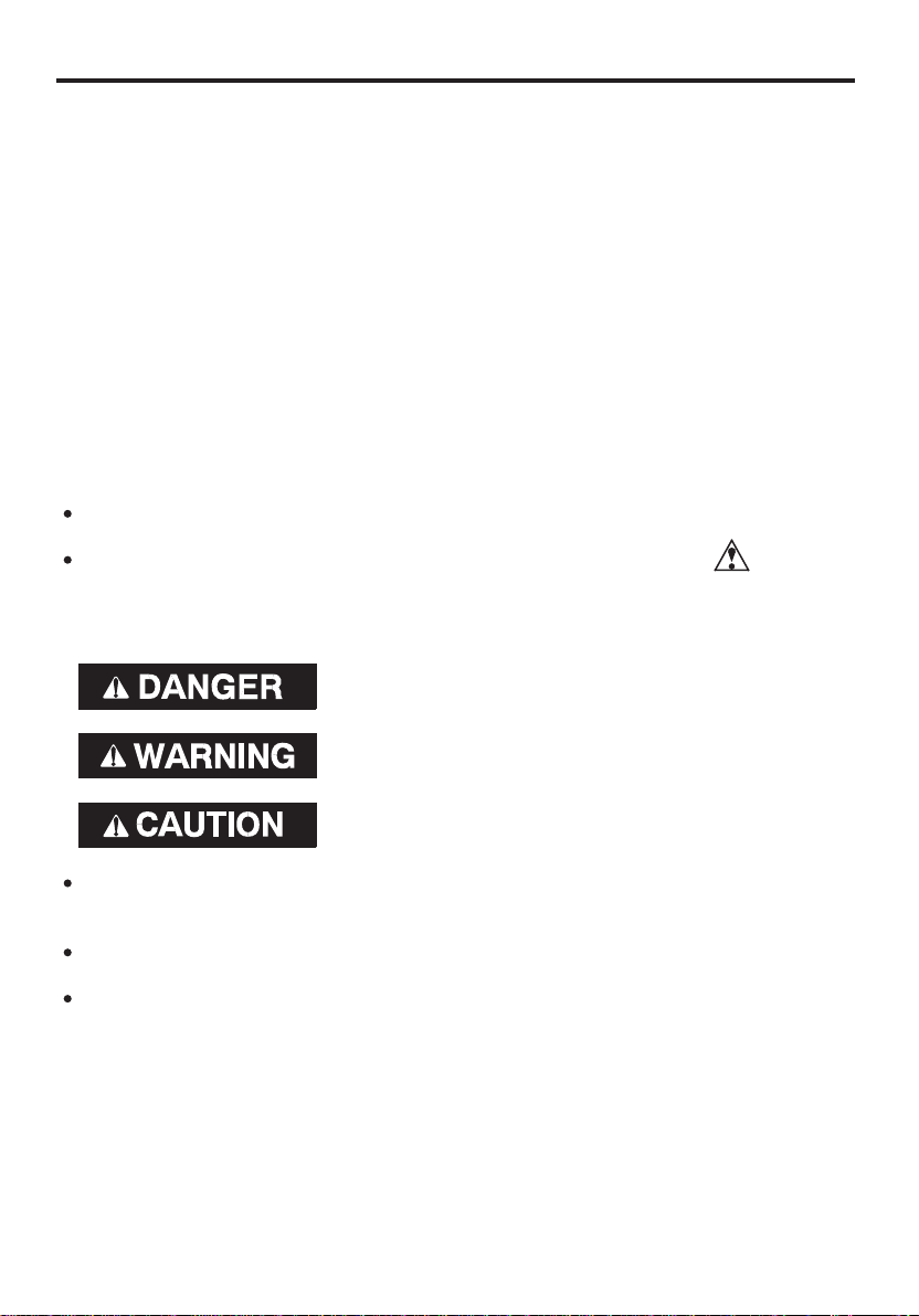
of three signal words, DANGER, WARNING, or CAUTION.
These signal words mean:
−
preceded by a safety alert symbol and one
−
Safety Headings
such as
−
You WILL KILLED SERIOUSLY HURT
you don’t follow instructions.
You CAN KILLED SERIOUSLY HURT
you don’t follow instructions.
You CAN HURT
tions.
be or if
be or if
be if you don’t follow instruc-
IMPORT ANT SAF ET Y
INFORMATION.
such as
Safety Section
Instructions
This entire book is filled with important safety information please
read it carefully.
−
how to use this generator correctly and safely.
−
GENERATOR SAFETY .
−
2

CONTENTS
..............................................................................GENERATOR SAFETY . 5
.......................................................................Safety Label Locations . 5
............................................................Important Safety Information . 6
..............................................................COMPONENT IDENTIFICATION . 8
..............................................................................................CONTROLS . 10
....................................................................................Engine Switch . 10
........................................................................................Starter Grip . 10
................................................................................Fuel Valve Lever . 11
..........................................................................................Choke Rod . 11
.............................................................................AC Circuit Breaker . 12
..........................................................................AC Circuit Protector . 13
.......................................................................Output Indicator Light . 14
....................................................................................DC Receptacle . 15
..........................................................................DC Circuit Protector . 15
...............................................................................Ground Terminal . 16
System . 17
..........................................................................................Engine Oil . 27
............................................................................................Refueling . 28
.............................................................................................Air Index . 36
..............................................................................Oil Alert
.......................Ground Fault Circuit Interrupter (GFCI) Receptacle . 18
...................................................................................GENERATOR USE . 21
..................................Connections to a Building ElectricalSystem . 21
.................................................................................Ground System . 21
.......................................................................Special Requirements . 21
.................................................................................AC Applications . 22
.....................................................................................AC Operation . 23
.....................................................................................DC Operation . 24
....................................................................High Altitude Operation . 26
.......................................................................PRE-OPERATION CHECK . 27
....................................................................Fuel Recommendations . 29
........................................................................STARTING THE ENGINE . 30
........................................................................STOPPING THE ENGINE . 31
......................................................................................MAINTENANCE . 32
......................................................The Importance of Maintenance . 32
..........................................................................Maintenance Safety . 33
............................................Emission Control SystemInformation . 34
.....................................................................Maintenance Schedule . 37
............................................................................Engine Oil Change . 38
...........................................................................Air Cleaner Service . 39
............................................................................Spark Plug Service . 41
...........................................................Fuel Sediment Cup Cleaning . 43
............................................................Spark Arrester Maintenance . 44
3

..................................................................TRANSPORTING/STORAGE . 45
......................................................................................Transporting . 45
...............................................................................................Storage . 46
.............................................................................TROUBLESHOOTING . 48
.................................................................................WIRING DIAGRAM . 50
....................................................................................SPECIFICATIONS . 51
.................................................WARRANTY SERVICE INFORMATION . 52
..............................................................Dealer Locator Information .52
.........................................................Customer Service Information . 52
...........................................................................Honda Publications . 53
......................................................................................................INDEX . 54
4
GENERATOR SAFETY
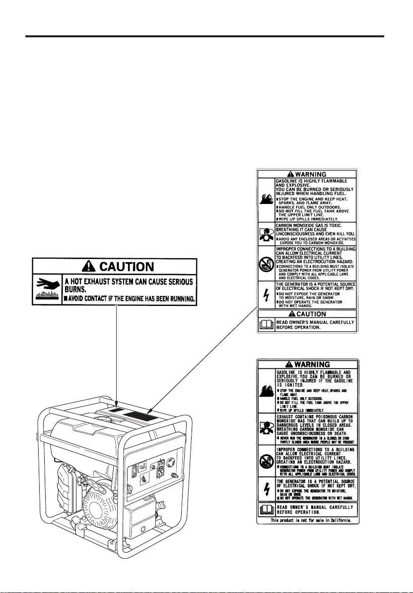
SAFETY LABEL LOCATIONS
These labels warn you of potential hazards that can cause serious
injury. Read them carefully.
If a label comes off or becomes hard to read, contact your Honda
servicing dealer for a replacement.
CALIFORNIA TYPE
NON-CALIFORNIA TYPE
5

IMPORTANT SAFETY INFORMATION
Honda generators are designed to give safe and dependable service if
operated according to instructions. Read and understand this owner’s
manual before operating your generator. You can help prevent
accidents by being familiar with your generator’s controls, and by
observing safe operating procedures.
Operator Responsibility
Know how to stop the generator quickly in case of emergency.
Understand the use of all generator controls, output receptacles,
and connections.
Be sure that anyone who operates the generator receives proper
instruction. Do not let children operate the generator without
parental supervision.
Carbon Monoxide Hazards
Exhaust contains poisonous carbon monoxide, a colorless and
odorless gas. Breathing carbon monoxide can cause loss of
consciousness and may lead to death.
If you run the generator in an area that is confined, or even partially
enclosed area, the air you breathe could contain a dangerous
amount of exhaust gas.
Never run your generator inside a garage, house or near open
windows or doors.
6

Electric Shock Hazards
The generator produces enough electric power to cause a serious
shock or electrocutionif misused.
Using a generator or electrical appliance in wet conditions, such as
rain or snow, or near a pool or sprinkler system, or when your hands
are wet, could result in electrocution. Keep the generator dry.
If the generator is stored outdoors, unprotected from the weather,
check the Ground Fault Circuit Interrupter (GFCI) receptacle, and all
other electrical components on the control panel before each use.
Moisture or ice can cause a malfunction or short circuit in electrical
components which could result in electrocution.
Do not connect to a building electrical system unless an isolation
switch has been installed by a qualified electrician.
Fire and Burn Hazards
The exhaust system gets hot enough to ignite some materials.
−
Keep the generator at least 3 feet (1 meter) away from buildings
and other equipment during operation.
−
Do not enclose the generator in any structure.
−
Keep flammable materialsaway from the generator.
The muffler becomes very hot during operation and remains hot for
a while after stopping the engine. Be careful not to touch the muffler
while it is hot. Let the engine cool before storing the generator
indoors.
Gasoline is extremely flammable and is explosive under certain
conditions. Do not smoke or allow flames or sparks where the
generator is refueled or where gasoline is stored. Refuel in a wellventilated area with the engine stopped.
Fuel vapors are extremely flammable and may ignite after the
engine has started. Make sure that any spilled fuel has been wiped
up before starting the generator.
7
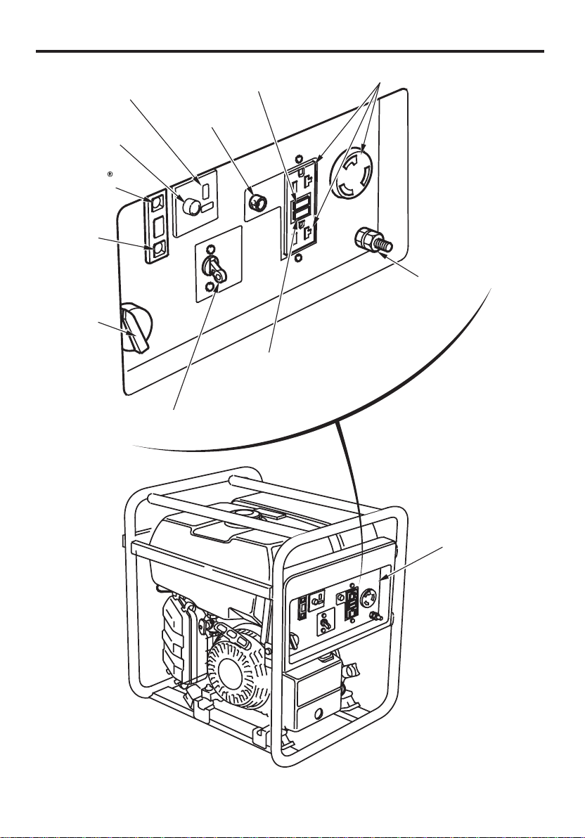
COMPONENT IDENTIFICATION
DC RECEPTACLE
DC CIRCUIT
PROTECTOR
OIL ALERT
INDICATOR
LIGHT
OUTPUT
INDICATOR
LIGHT
ENGINE
SWITCH
AC CIRCUIT
PROTECTOR
AC CIRCUIT BREAKER
TEST BUTTON
RESET BUTTON
AC RECEPTACLES
GROUND TERMINAL
8
CONTROL PANEL
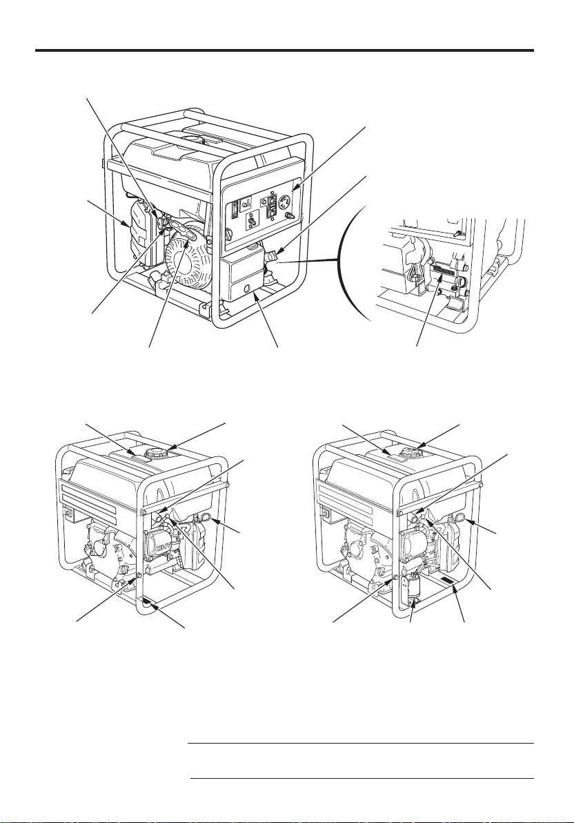
FUEL VALVE LEVER
AIR
CLEANER
FUEL SEDIMENT
CUP
STARTER GRIP
CYCLOCONVERTER
UNIT
CALIFORNIA TYPENON-CALIFORNIA TYPE
CONTROL PANEL
OIL FILLER CAP/DIPSTICK
TM
ENGINE SERIAL NUMBER
FUEL GAUGE
OIL DRAIN PLUG
FUEL TANK CAP
MUFFLER
CHOKE
ROD
SPARK PLUG
CAP
FRAME SERIAL
NUMBER
FUEL GAUGE
PLUG
FUEL TANK CAP
MUFFLER
CHOKE
ROD
SPARK PLUG
CAP
CANISTEROIL DRAIN
FRAME SERIAL
NUMBER
Record the engine and frame serial numbers for your future reference.
Refer to these serial numbers when ordering parts, and when making
technical or warrantyinquiries (see page ).
52
Frame serial number:
Engine serial number:
9
CONTROLS
ENGINE SWITCH
To start and stop the engine.
Switch position:
OFF:
ON:
To stop the engine.
To start and run the engine.
OOFFFF
ENGINE SWITCH
OONN
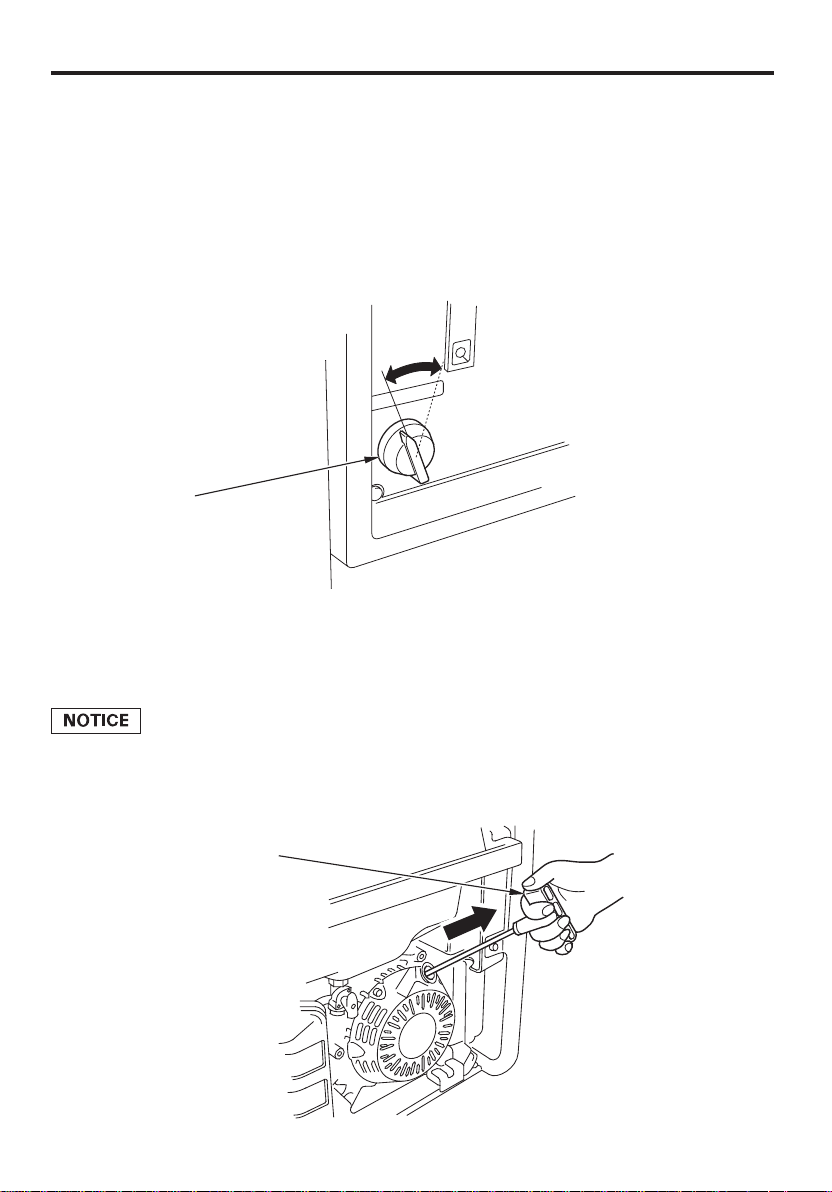
STARTER GRIP
To start the engine, pull the starter grip lightly until you feel resistance,
then pull briskly in the direction of the arrow as shown below.
Do not allow the starter grip to snap back against the engine. Return it
gently to prevent damage to the starter.
STARTER GRIP
DDiirreeccttiioonn ttoo ppuullll
10
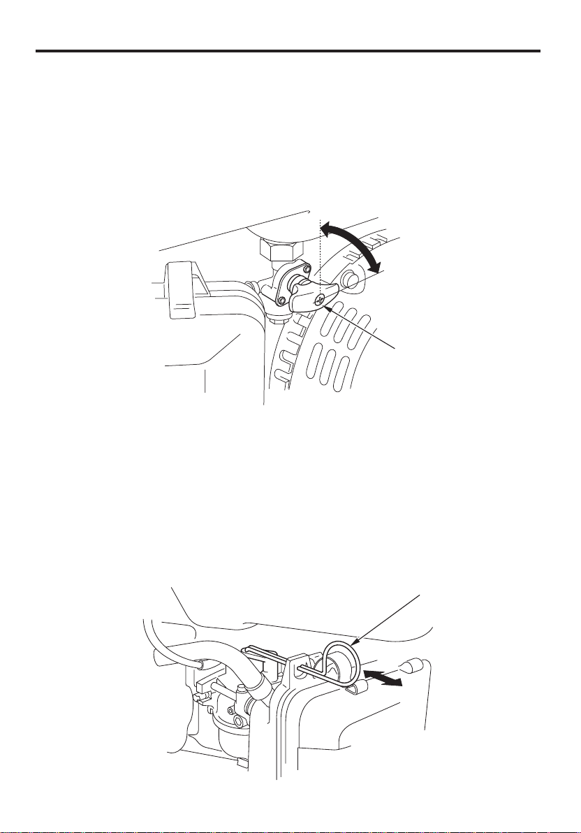
FUEL VALVE LEVER
The fuel valve is located between the fuel tank and carburetor. When
the valve lever is in the ON position, fuel is allowed to flow from the
fuel tank to the carburetor. Be sure to return the fuel valve lever to the
OFF position after stopping the engine.
OONN
OFF
FUEL VALVE LEVER
CHOKE ROD
The choke rod opens and closes the choke valve in the carburetor.
Pulling the choke rod to the CLOSED position enriches the fuel mixture
for starting a cold engine.
Pushing the choke rod to the OPEN position provides the correct fuel
mixture for operation after starting, and for restartinga warm engine.
CHOKE ROD
OOPPEENN
CCLLOOSSEEDD
11
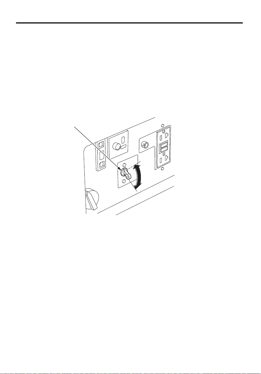
AC CIRCUIT BREAKER
The AC circuit breaker will automatically switch OFF if there is a short
circuit or an overload of the generator at the AC receptacle. If the AC
circuit breaker is switched OFF automatically, check that the appliance
is working properly and does not exceed the rated load capacity of the
AC circuit before switching the AC circuit breaker ON again.
The AC circuit breaker may be used to switch the generator AC power
ON or OFF.
AC CIRCUIT BREAKER
OONN
OOFFFF
12
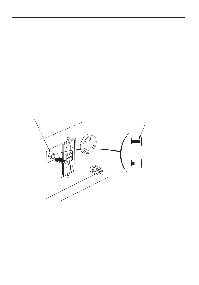
AC CIRCUIT PROTECTOR
The AC circuit protector will automatically shut off the AC output
power if there is a short circuit or an overload of the generator at the
20A receptacle.
The yellow indicator inside the clear circuit protector button will pop
out to show that the circuit protector has switched OFF. Wait a few
minutes and push the button in to reset the circuit protector, and then
restart the engine.
If the circuit protector is switched OFF, check that the appliance is
working properly and does not exceed the rated load capacity of the
circuit before switching the circuit protector ON again.
AC CIRCUIT PROTECTOR
YELLOW INDICATOR
:OFF
:: OONN
13
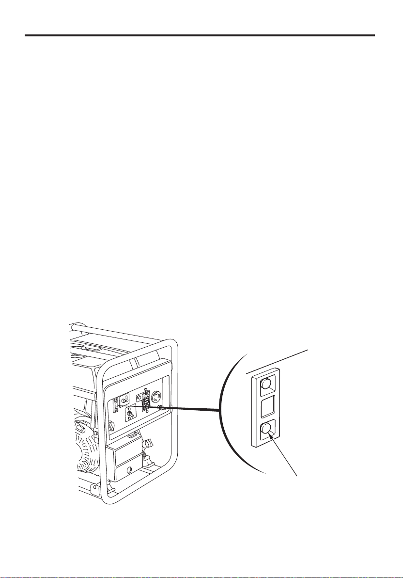
OUTPUT INDICATOR LIGHT
The output indicator light (green) will remain ON during normal
operating conditions.
If there is a short circuit in a connected appliance or if the
CycloConverter unit overheats, the output indicator light (green)
TM
blinks and current to the connected appliance(s) will shut off. When
this happens, disconnect the appliance(s) and stop the engine to
investigate the problem.
Determine if the cause is a short circuit in a connected appliance or an
overheated CycloConverter unit. Correct the problem and restart the
engine.
If the output indicator light (green) blinks again, consult your Honda
generator dealer.
The output indicator light (green) may blink at intervals of 2.5 seconds
depending on connected appliance(s) to the AC receptacles. It
indicates that the output voltage has dropped slightly. It does not
matter as long as the connected appliances work properly.
14
OUTPUT INDICATOR
LIGHT (GREEN)
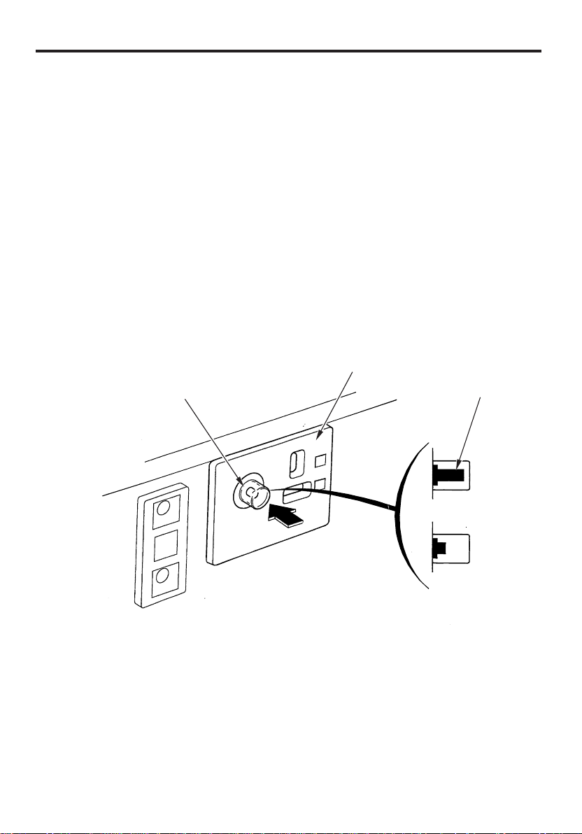
DC RECEPTACLE
The DC receptacle may ONLY be used for charging 12 volt automotive
type batteries.
DC CIRCUIT PROTECTOR
The DC circuit protector automatically shuts off the DC battery
charging circuit when the DC charging circuit is overloaded, when
there is a problem with the battery, or when the connections between
the battery and the generator are improper.
The yellow indicator inside the clear circuit protector button will pop
out to show that the circuit protector has switched OFF. Wait a few
minutes and push the button in to reset the circuit protector.
DC RECEPTACLE
DC CIRCUIT PROTECTOR
(CLEAR BUTTON)
YELLOW INDICATOR
:OFF
PUSH
:ON
15
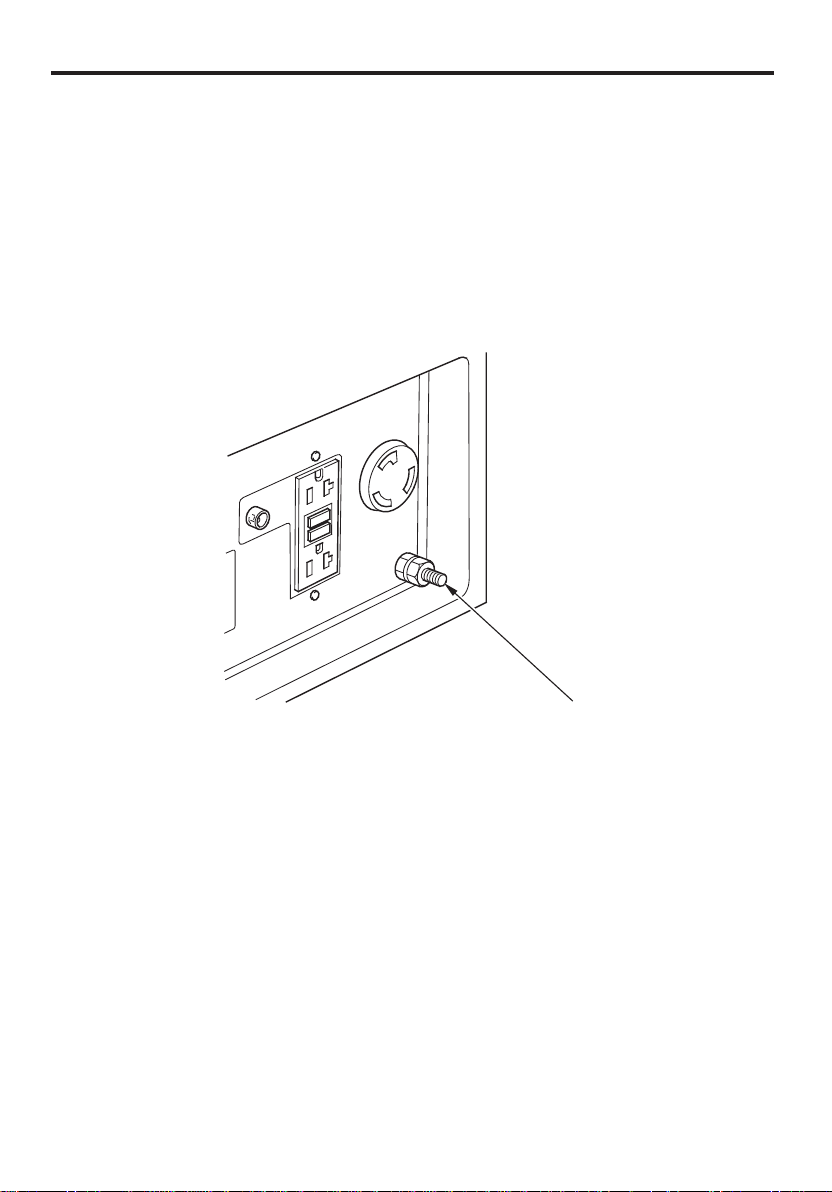
GROUND TERMINAL
The generator ground terminal is connected to the frame of the
generator, the metal non-current-carrying parts of the generator, and
the ground terminals of each receptacle.
Before using the ground terminal, consult a qualified electrician,
electrical inspector or local agency having jurisdiction for local codes
or ordinances that apply to the intended use of the generator.
16
GROUND TERMINAL
 Loading...