


Thank you for purchasing a Honda generator.
This manual describes operation and maintenance of the Honda EB12D
Generator. All information in this publication is based on the latest product
information available at the time of printing. Honda Motor Co., Ltd,
reserves the right to make changes at any time without notice and without
incurring any obligation.
No part of this publication may be reproduced without written permission.
This manual is a permanent part of the generator, and it must stay with the
generator if resold.
The Honda EB12D generator is not factory equipped with a spark arrester.
In some areas, it is illegal to operate an engine without a USDA-qualified
spark arrester. Check local laws and regulations before operating. An op-
tional spark arrester is available from an authorized Honda generator
dealer.
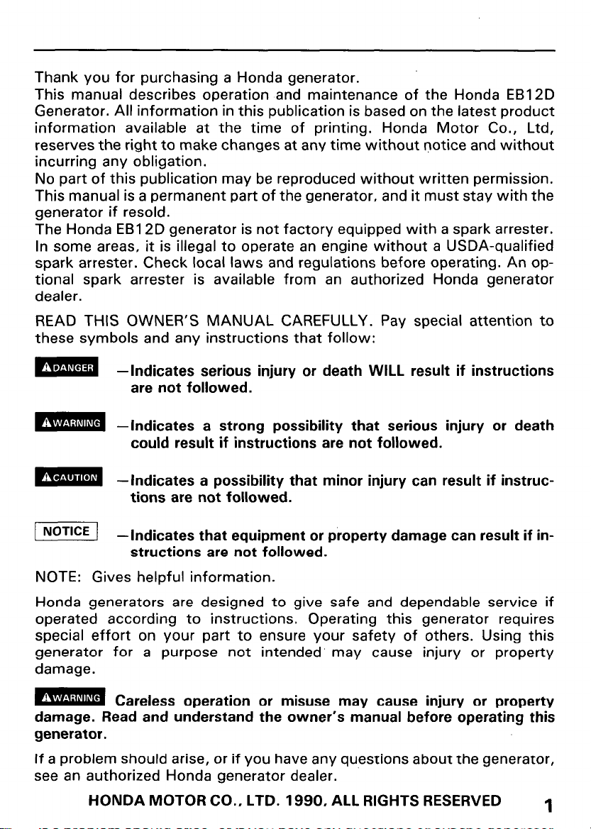
READ THIS OWNER’S MANUAL CAREFULLY. Pay special attention to
these symbols and any instructions that follow:
m
m -Indicates a strong possibility that serious injury or death
m
m -Indicates that equipment or property damage can result if in-
NOTE: Gives helpful information.
Honda generators are designed to give safe and dependable service if
operated according to instructions. Operating this generator requires
special effort on your part to ensure your safety of others. Using this
generator for a purpose not intended’ may cause injury or property
damage.
m
damage. Read and understand the owner’s manual before operating this
generator.
If a problem should arise, or if you have any questions about the generator,
see an authorized Honda generator dealer.
-Indicates serious injury or death WILL result if instructions
are not followed.
could result if instructions are not followed.
-Indicates a possibility that minor injury can result if instructions are not followed.
structions are not followed.
Careless operation or misuse may cause injury or property
HONDA MOTOR CO., LTD. 1990, ALL RIGHTS RESERVED
1
CONTENTS
1. SAFETY INFORMATION
2. COMPONENT IDENTIFICATION
3. CONTROLS
Engine switch
Circuit breaker
Circuit protector
Ground Fault Circuit Interrupter (GFCI) Receptacle
Fuel meter
Hour meter
Indicator lights
4. PRE-OPERATION CHECKS
Maintenance cover opening and closing
Engine oil
Fuel
Coolant
Fuel filter
Battery
Indicator lights
5. STARTING AND STOPPING THE ENGINE
Starting the engine
Stopping the engine
6. GENERATOR USE
7. MAINTENANCE .................................................................
Tool kit
Maintenance schedule
Engine oil change
Air cleaner
Fuel filter
Battery
Fuse replacement
8. TRANSPORTING AND STORAGE
9. TROUBLESHOOTING
10. SPECIFICATIONS
11. WIRING DIAGRAM
12. WARRANTY SERVICE
.......................................................................
..................................................................
.................................................................
...............................................................
.......................................................................
......................................................................
.................................................................
........................................................................
...............................................................................
..........................................................................
........................................................................
...........................................................................
.................................................................
...........................................................................
.......................................................................
........................................................................
...........................................................................
......................................................
............................................
...................................................
................................
...............................
...........................................................
..........................................................
..............................................................
.......................................................
..............................................................
.............................................................
..........................................
..........................................................
...............................................................
.............................................................
. . . . . . . . . . . . . . . . . . . . . . . . . . . . . . . . . . . . . . . . . . . . . . . . . . . . . . . . .
.................
3
5
7
7
8
8
9
10
10
11
13
13
14
15
17
18
::
21
21
24
26
32
32
33
34
35
37
38
40
41
43
44
45
46
2

I. SAFETY INFORMATION
SAFETY INFORMATION
For your safety and the safety of others, pay special attention to these
precautions:
Operator Responsibility
l
Know how to stop the generator quickly in case of emergency. Understand the use of all generator controls, output receptacles, and
connections.
l
Be sure that anyone who operates the generator receives proper in-
struction. Do not let children operate the generator without parental
supervision.
Electric Shock Hazards
l
The generator produces enough electric power to cause a serious shock
or electrocution if misused.
l
Using a generator or electrical appliance in wet conditions, such as rain
or snow, or near a pool or sprinkler system, or when your hands are
wet, could result in electrocution. Keep the generator dry.
l
If the generator is stored outdoors, unprotected from the weather,
check the Ground Fault Circuit Interrupter (GFCI) receptacle, and all
other electrical components on the control panel, before each use.
Moisture or ice can cause a malfunction or short circuit in electrical
components which could result in electrocution.
l
Do not connect to a building’s electrical system unless an isolation
switch has been installed by a qualified electrician.
Fire and Burn Hazards
l
The exhaust system gets hot enough to ignite some materials.
- Keep the generator at least 1 meter (3 feet) away from buildings and
other equipment during operation.
- Keep flammable materials away. from the generator.
l
The muffler becomes very hot during operation and remains hot for
while after stopping the engine. Be careful not to touch the muffler
while it is hot. Let the engine cool before storing the generator indoors.
l
Diesel fuel is flammable, and fuel vapor can explode. Refuel in a well
ventilated area with the engine stopped. Keep flames and sparks away,
and do not smoke in the area.
l
Diesel fuel may spill and ignite if the generator is tilted or overturned.
Place the generator on a firm, level surface. Avoid loose sand or snow.
Carbon Monoxide Hazards
l
Exhaust contains poisonous carbon monoxide, a colorless and odorless
gas. Breathing exhaust can cause loss of consciousness and may lead
to death.
l
If you run the generator in an area that is confined, or even partially
enclosed, the air you breathe could contain a dangerous amount of exhaust gas. To keep exhaust gas from building up, provide adequate
ventilation.
3
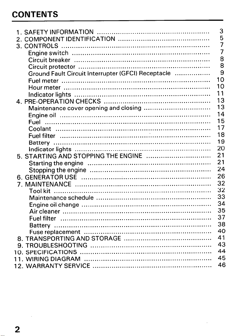
WARNING LABEL LOCATION
Read these labels before operating the generator.
Your Honda generator comes with several labels containing important
safety information. Anyoune who uses the generator should read and
understand this information before operating the generator.
The labels should be considered as permanent parts of the generator. If a
label comes off or becomes hard to read, contact an authorized Honda
generator dealer for replacements.
I ELECTROCUTION OR PROPERTY DAMAGE CAN OCCUR.
I DO NOT CONNECT THIS GENERATOR TO ANY BUILDING’S
ELECTRICAL SYSTEM UNLESS AN ISOLATION SWITCH
HAS BEEN INSTALLED BY A LICENSED ELECTRICIAN.
INEVER RUN THE ENGINE IN AN ENCLOSED AREA.
lTHE EXHAUST CONTAINS POISONOUS CARBON MONO-
XIDE GAS THAT CAN CAUSE LOSS OF CONSCIOUSNESS
AND MAY LEAD TO DEATH.
I READ OWNER’S MANUAL CAREFULLY.
\
@
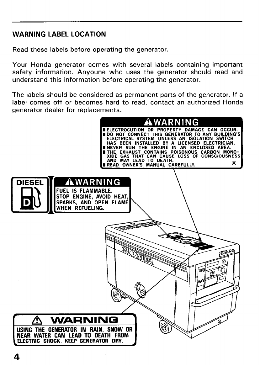
2. COMPONENT IDENTIFICATION
COOLING AIR OLJTLET
MAINTENANCE COVE
MAINTENANCE COVER
EXHAUST OUTLET
/ LIFTIYG HOOK
, FUEL FILLER CAP
TEST RECORD
ENGINE OIL FILLER CAP
PANEL
OOLANT RESERVE TANK
OIL LEVEL GAUG
)OLANT DRAIN
ENGINE OIL DRAIN BOLT
FRAME SERIAL NLkMBER
BOL
I 68%
FUEL DRAIN BOLT
\w ’
d
FUEL FILTER
L
TTERY
* Record the frame serial number for your reference. Refer to the serial
number when ordering parts, and when making technical or warranty inquiries (see page 46).
Frame serial number:
5
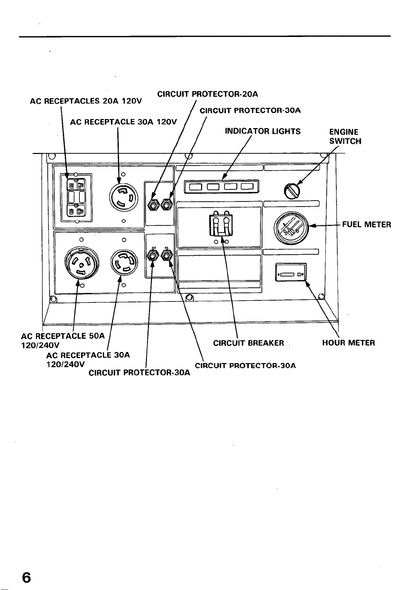
AC RECEPTACLES 20A 120V
AC RECEPTACLE 30A 12OV
I
AC I
1201
TACLE 50A
I24OV
AC RECEPTACLk 30A
120124OV
I
I
CIRCUIT PROTECTOR-BOA
CIRCUIT PROTECTOR-2OA
I
/
CIRCUIT PROTECTOR-30A
INDICATOR LIGHTS
CIRdIT BREAKER
\
\
CIRCUIT PROTECTOR-30A
ENGINE
sv
/
VITCH
/
,
: FUEL METER
a
\
IU iR METER
6
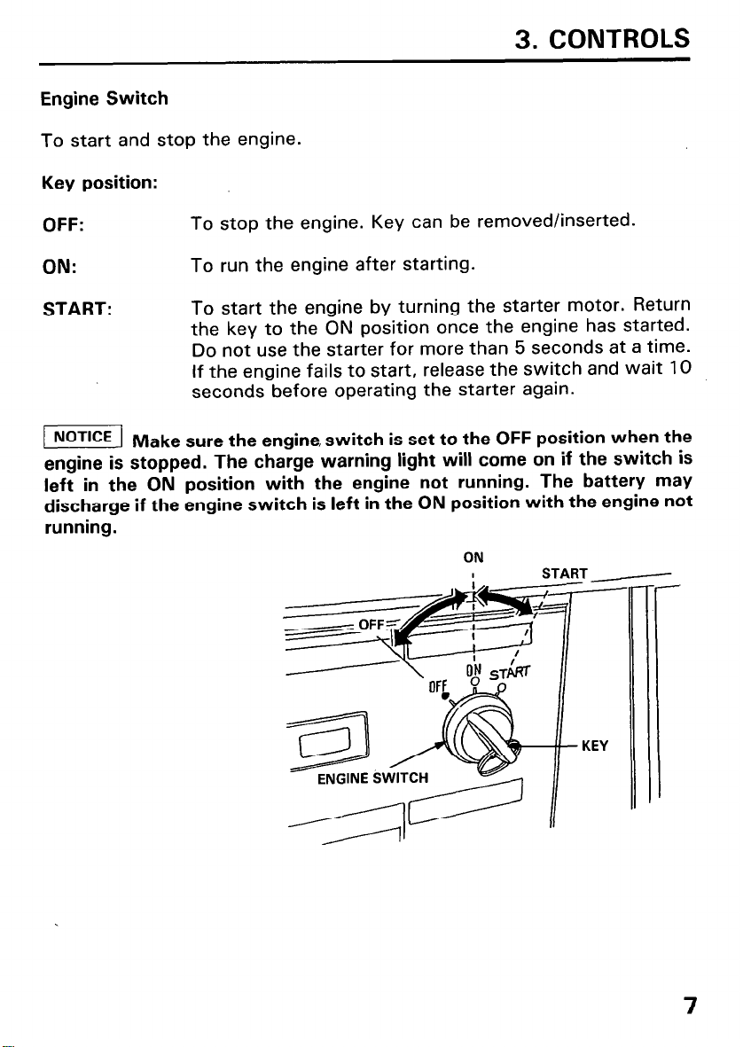
Engine Switch
To start and stop the engine.
Key position:
3. CONTROLS
OFF:
ON:
START: To start the engine by turning the starter motor. Return
w Make sure the engine, switch is set to the OFF position when the
engine is stopped. The charge warning light will come on if the switch is
left in the ON position with the engine not running. The battery may
discharge if the engine switch is left in the ON position with the engine not
running.
To stop the engine. Key can be removed/inserted.
To run the engine after starting.
the key to the ON position once the engine has started.
Do not use the starter for more than 5 seconds at a time.
If the engine fails to start, release the switch and wait 10
seconds before operating the starter again.
ON
KEY
7
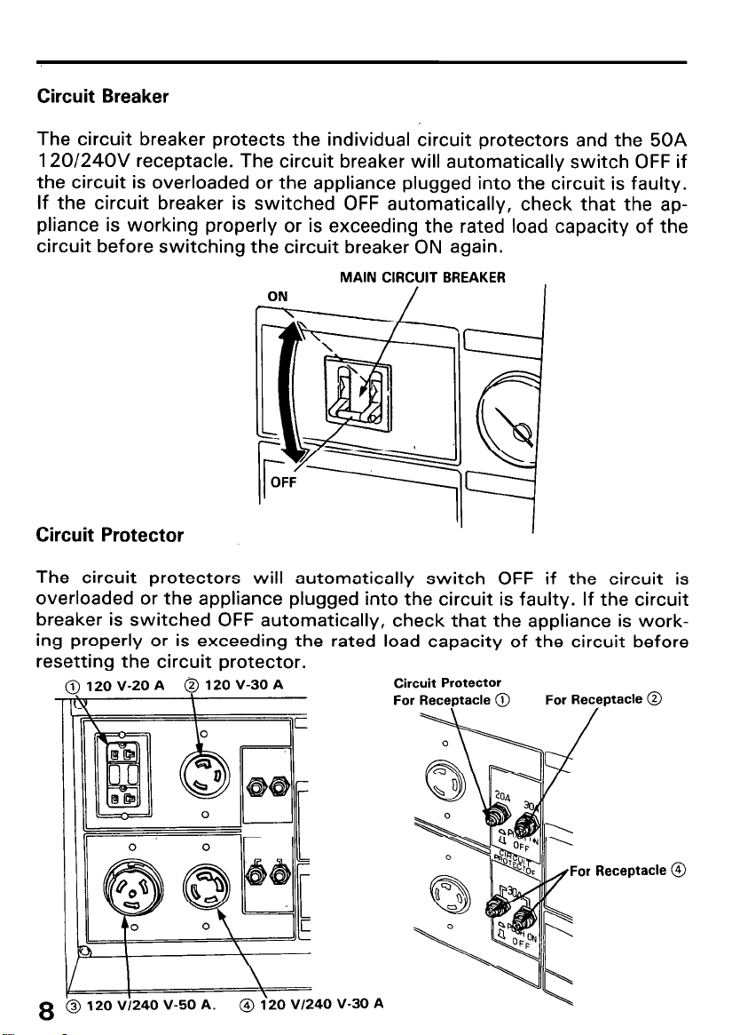
Circuit Breaker
The circuit breaker protects the individual circuit protectors and the 50A
120/24OV receptacle. The circuit breaker will automatically switch OFF if
the circuit is overloaded or the appliance plugged into the circuit is faulty.
If the circuit breaker is switched OFF automatically, check that the appliance is working properly or is exceeding the rated load capacity of the
circuit before switching the circuit breaker ON again.
MAIN CIRCUIT BREAKER
Circuit Protector
The circuit protectors will automatically switch OFF if the circuit is
overloaded or the appliance plugged into the circuit is faulty. If the circuit
breaker is switched OFF automatically, check that the appliance is working properly or is exceeding the rated load capacity of the circuit before
resetting the circuit protector.
@12OV-20A @lZOV-30A
q.
\
I K-
Circuit Protector
For Receptacle @
For Receptacle @
/
8 ‘oVv)240 V-50 A.
@ i20 VI240 V-30 A
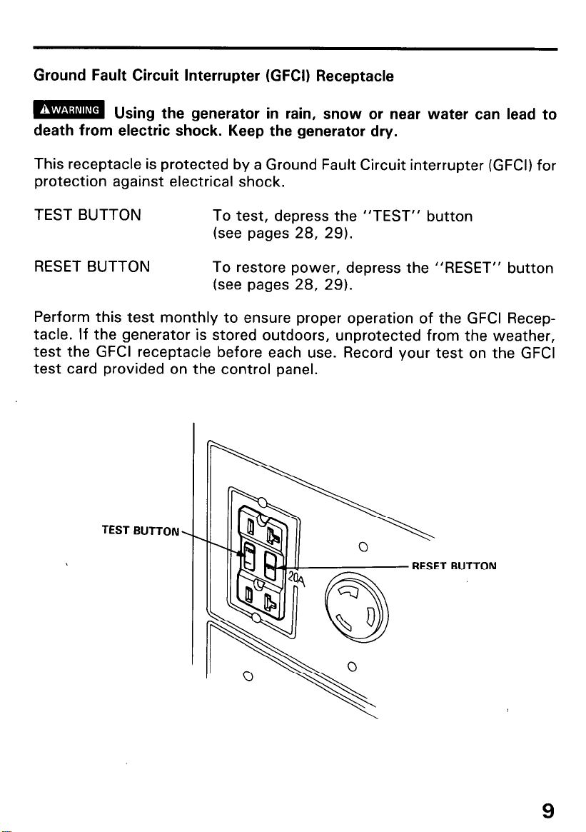
Ground Fault Circuit Interrupter (GFCI) Receptacle
m Using the generator in rain, snow or near water can lead to
death from electric shock. Keep the generator dry.
This receptacle is protected by a Ground Fault Circuit interrupter (GFCI) for
protection against electrical shock.
TEST BUTTON
To test, depress the “TEST” button
(see pages 28, 29).
RESET BUTTON
To restore power, depress the “RESET” button
(see pages 28, 29).
Perform this test monthly to ensure proper operation of the GFCI Receptacle. If the generator is stored outdoors, unprotected from the weather,
test the GFCI receptacle before each use. Record your test on the GFCI
test card provided on the control panel.
TEST
BUTTON
BUTTON
9
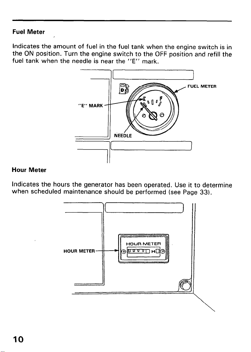
Fuel Meter
Indicates the amount of fuel in the fuel tank when the engine switch is in
the ON position. Turn the engine
fuel tank when the needle is near the “E” mark.
switch to the OFF position and refill the
FUEL METER
I
71
Hour Meter
Indicates the hours the gener,ator has been operated. Use it to determine
when scheduled maintenance should be performed (see Page 33).
10
HOUR METER
Indicator Lights
The EB12D generator is equipped with four indicator lights that monitor
three engine functions and the generator operation. All four lights come on
when the engine switch is turned from the OFF position to the ON posi-
tion. This allows the operator to check the bulbs of each indicator light.
The for lights will stay on for 4 seconds with the engine switch left in the
ON position. The lights will go out if the engine switch is turned to the
start position before 4 seconds.
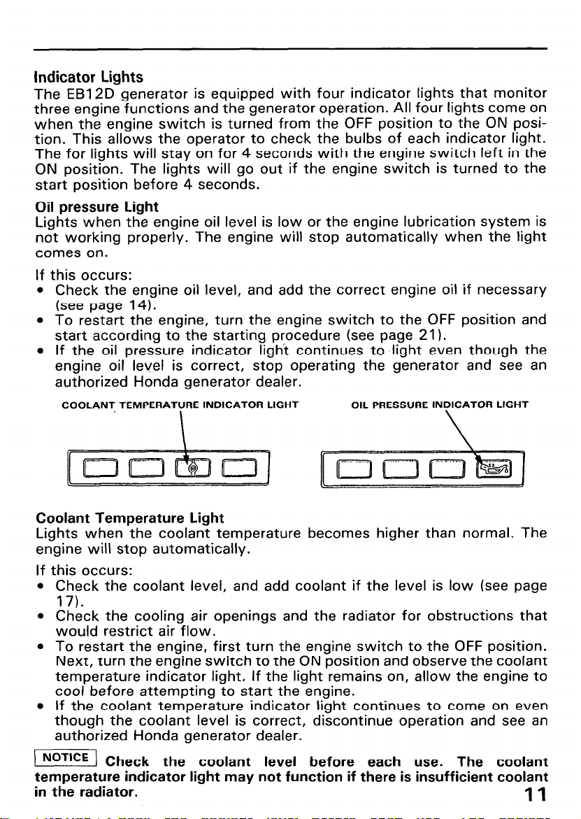
Oil pressure Light
Lights when the engine oil level is low or the engine lubrication system is
not working properly. The engine will stop automatically when the light
comes on.
If this occurs:
l Check the engine oil level, and add the correct engine oil if necessary
(see page 14).
l To restart the engine, turn the engine switch to the OFF position and
start according to the starting procedure (see page 21 I.
l If the oil pressure indicator light continues to light even though the
engine oil level is correct, stop operating the generator and see an
authorized Honda generator dealer.
COOLANT TEMPERATURE INDICATOR LIGHT
OIL PRESSURE INDICATOR LIGHT
Coolant Temperature Light
Lights when the coolant temperature becomes higher than normal. The
engine will stop automatically.
If this occurs:
l Check the coolant level, and add coolant if the level is low (see page
17).
l Check the cooling air openings and the radiator for obstructions that
would restrict air flow.
l To restart the engine, first turn the engine switch to the OFF position.
Next, turn the engine switch to the ON position and observe the coolant
temperature indicator light. If the light remains on, allow the engine to
cool before attempting to start the engine.
l If the coolant temperature indicator light continues to come on even
though the coolant level is correct, discontinue operation and see an
authorized Honda generator dealer.
NoT’CE Check the coolant level before each use. The coolant
temperature indicator light may not function if there is insufficient coolant
in the radiator.
11
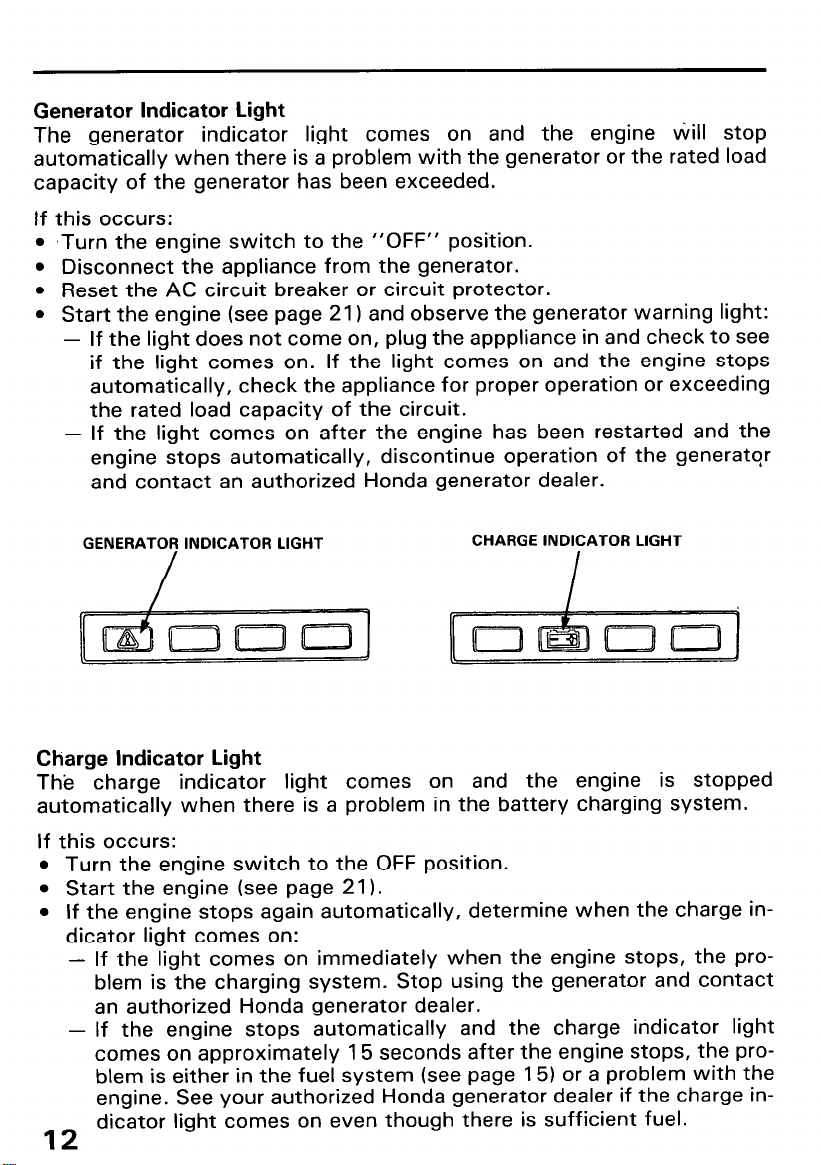
Generator Indicator Light
The generator indicator light comes on and the engine Will stop
automatically when there is a problem with the generator or the rated load
capacity of the generator has been exceeded.
If this occurs:
l
,Turn the engine switch to the “OFF” position.
l
Disconnect the appliance from the generator.
l
Reset the AC circuit breaker or circuit protector.
l
Start the engine (see page 21) and observe the generator warning light:
-
If the light does not come on, plug the apppliance in and check to see
if the light comes on. If the light comes on and the engine stops
automatically, check the appliance for proper operation or exceeding
the rated load capacity of the circuit.
-
If the light comes on after the engine has been restarted and the
engine stops automatically, discontinue operation of the generator
and contact an authorized Honda generator dealer.
GENERATOR INDICATOR LIGHT
CHARGE INDICATOR LIGHT
Charge Indicator Light
The charge indicator light comes on and the engine is stopped
automatically when there is a problem in the battery charging system.
If this occurs:
l
Turn the engine switch to the OFF position.
l
Start the engine (see page 21).
l
If the engine stops again automatically, determine when the charge in-
dicator light comes on:
-
If the light comes on immediately when the engine stops, the problem is the charging system. Stop using the generator and contact
an authorized Honda generator dealer.
-
If the engine stops automatically and the charge indicator light
comes on approximately 15 seconds after the engine stops, the problem is either in the fuel system (see page 15) or a problem with the
engine. See your authorized Honda generator dealer if the charge in-
dicator light comes on even though there is sufficient fuel.
12
4. PRE-OPERATION CHECKS
Check these items before starting the generator. Be sure the generator is
on a level surface. Block the wheels if the optional wheel kit is installed.
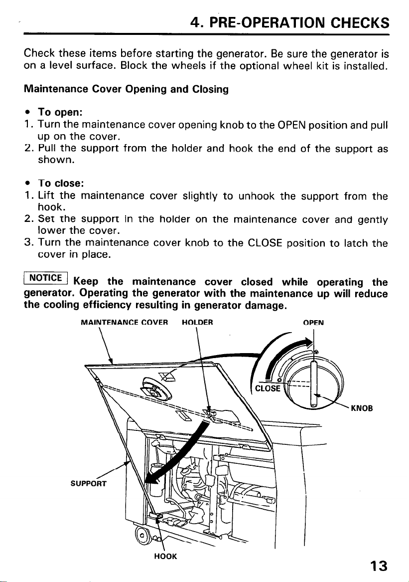
Maintenance Cover Opening and Closing
l
To open:
1. Turn the maintenance cover opening knob to the OPEN position and pull
up on the cover.
2. Pull the support from the holder and hook the end of the support as
shown.
l
To close:
1. Lift the maintenance cover slightly to unhook the support from the
hook.
2. Set the support in the holder on the maintenance cover and gently
lower the cover.
3. Turn the maintenance cover knob to the CLOSE position to latch the
cover in place.
( Ke
ep the maintenance cover closed while operating the
generator. Operating the generator with the maintenance up will reduce
the cooling efficiency resulting in generator damage.
MAINTENANCE COVER
HOLDER OPEN
KNOB
HOOK
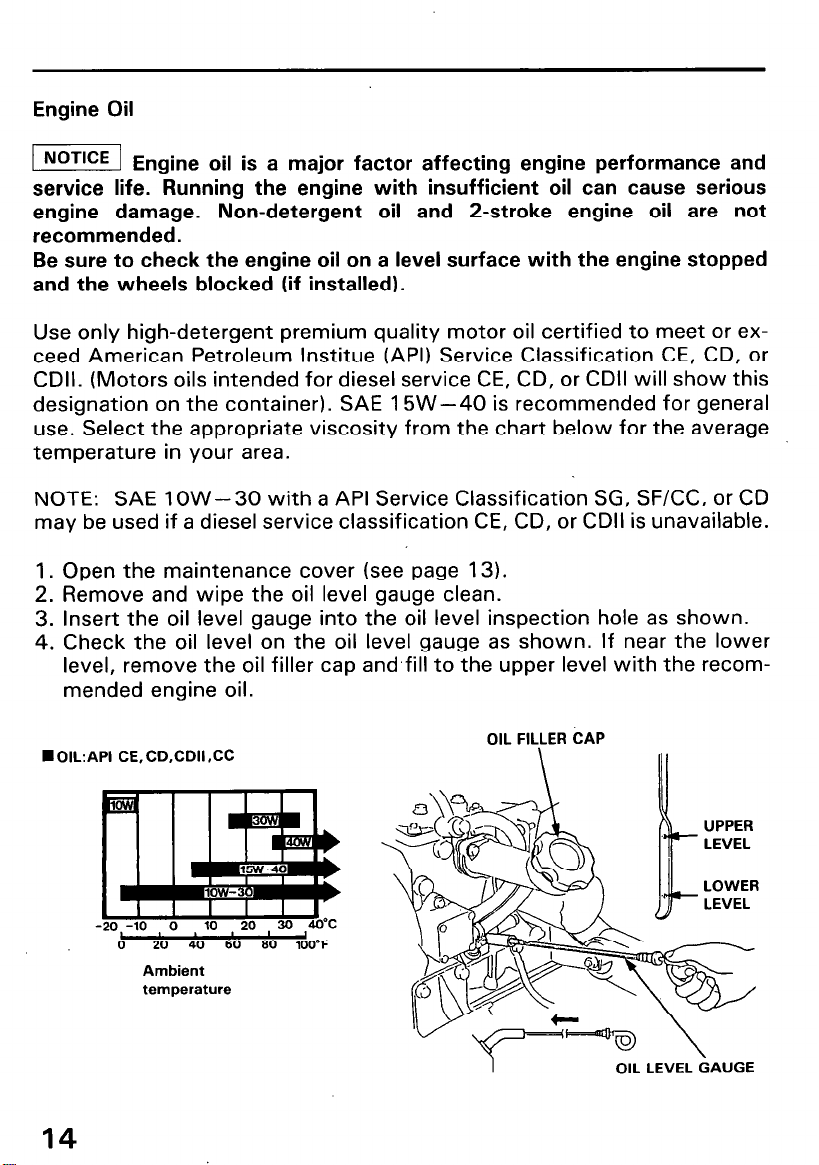
Engine Oil
-1 En
gine oil is a major factor affecting engine performance and
service life. Running the engine with insufficient oil can cause serious
engine damage. Non-detergent oil and 2-stroke engine oil are not
recommended.
Be sure to check the engine oil on a level surface with the engine stopped
and the wheels blocked (if installed).
Use only high-detergent premium quality motor oil certified to meet or exceed American Petroleum lnstitue (API) Service Classification CE, CD, or
CDII. (Motors oils intended for diesel service CE, CD, or CDII will show this
designation on the container). SAE 15W-40 is recommended for general
use. Select the appropriate viscosity from the chart below for the average
temperature in your area.
NOTE: SAE low-30 with a API Service Classification SG, SF/CC, or CD
may be used if a diesel service classification CE, CD, or CDII is unavailable.
1. Open the maintenance cover (see page 13).
2. Remove and wipe the oil level gauge clean.
3. Insert the oil level gauge into the oil level inspection hole as shown.
4. Check the oil level on the oil level gauge as shown. If near the lower
level, remove the oil filler cap and,fill to the upper level with the recommended engine oil.
n
OIL:API CE, CD,CDII SC
0
20 40 60 00 100°F
Ambient
temperature
14
OIL FILLER CAP
1
OIL LEVEL GAUGE

Fuel
Fuel tank capacity: 38 lit. (IO US gal, 8.4 Imp. gal1
Turn the engine switch ON and check the fuel meter.
Refill the tank to the upper level if necessary. Do not fill the fuel tank above
the upper level mark.
Use ONLY clean high-quality fuel.
Recommended fuel specifications: ASTM D-975-l -D/2-D
Use No. 2-D fuel at temperatures above 20°F (-7OC)
Use No. 1-D fuel at temperatures below 20°F (-7OC)
Use No. 1 -D fuel for all temperatures at altitudes above 5000 ft (1500 m).
Diesel fuel with a cetane rating as low as 40 may be used, but a cetane
rating of 45 is recommended.
Do not use contaminated diesel fuel.
Do not mix different grades of diesel fuels.
Avoid getting dirt, dust or water in the fuel tank.
After refueling, be sure to tighten the fuel tank cap securely.
l
Diesel fuel is flammable and explosive under certain conditions. Refuel
in a well ventilated area with the engine stopped.
l
Do not smoke or allow flames or sparks in the area where the engine is
refueled or where diesel fuel is stored.
l
Do not overfill the tank, and make sure the filler cap is securely closed
after refueling.
l
Be careful not to spill fuel when refueling. Spilled fuel vapor may ignite.
If fuel is spilled, make sure the area is dry before starting the engine.
l
Use diesel fuel only. Do not use gasoline, kerosene or any other fuel
oils. Do not mix gasoline with diesel fuel.
UPPER LEVEL
ON
--ENGINE
FUEL
15

NOTE:
l
Depending on the season and the ambient temperature, a different
grade of diesel fuel should be used. If a summer grade fuel is used in the
winter, the summer fuel may freeze preventing the engine from starting. Winter grade fuel is used in the summer could result in a lack of
engine power. Be sure to use the proper grade of diesel fuel which complies with the ambient temperature.
l
Keep the fuel tank filled in the winter. Water can accumulate from condensation if the tank is kept only partially filled. Refill the fuel tank after
each use.
l
Check the fuel filter before each use for water and contaminates. Service the fuel filter if any contaminates are found (see page 18).
Air Bleeding
The generator is equipped with an automatic air bleeding system in the
event the engine is run out of fuel. Refill the tank (see page 15). Make sure
that fuel is supplied to the fuel filter, then start the engine (see page 21).
NOTE: Light blue exhaust will be seen and the engine speed may fluctuate as air bleeding is occuring. This is normal. Run the engine without a
load until the engine speed stabilizes and the exhaust smoke clears.
16

Coolant
1.
Open the maintenance cover (see page 13).
2.
Check the coolant level in the reserve tank when the engine is at normal
operating temperature.
If the level is near the MIN level, add coolant to bring it up to the MAX
level (see page 18 for coolant recommendation).
MAX (UPPER
MIN (LOWER
LEVEL)
I
LEVEL)
TANK
3. If there is no coolant in the reserve tank, the cooling system should be
checked for leaks and repaired if necessary. Coolant must then be add-
ed to the radiator and reserve tank.
m
The coolant is hot and under pressure and sever scalding
could result. Never remove the radiator cap when the engine is hot.
Wait until the engine is cool, then turn the radiator cap
counterclockwise until it stops.
DO NOT PRESS DOWN WHILE
TURNING THE CAP. After any remaining pressure has been relieved,
remove the cap
by pressing down and again turning it
counterclockwise. Add enough coolant to fill the radiator, and reinstall
the cap. Be sure to tighten it securely. Fill the reserve tank up to the
MAX level with the engine cold. Recheck the reserve tank once the
engine reaches normal operating temperature.
17

Coolant Recommendation
Use high quality ethylene glycol antifreeze that is specifically formulated
for use in aluminum engines. Mix the antifreeze with low-mineral drinking
water or distilled water.
A 50/50 mixture of ethylene glycol antifreeze and water is recommended
for most temperature and provides good corrosion brotection. A higher
concentration of antifreeze decrease cooling efficiency and is recommended only if additional protection against freezing is needed. A concentration
of less than 40% antifreeze will not provide proper corrosion protection.
[ NOTICE ] Th
cause corrosion damage that will shorten the life of the engine.
Fuel Filter
1. Open the maintenance cover (see page 13).
2. Inspect the fuel filter for dirt, water, or other contaminates and clean
the fuel filter if necessary (see page 37).
e use of unsuitable antifreeze, hard water, or salt water will
FUEL STRAINER
18
STRAINEi ELEMENT

Battery
The electrolyte level must be kept between the UPPER and LOWER level
marks. If the electrolyte level is near the LOWER level, remove the battery
filler caps and carefully add distilled water to the upper level line (see page
38).
UPPER LEVEL
LOWER LEVEL
m
or skin causes burns. Wear protective clothing and use eye protection
when working near the battery.
POISON-KEEP OUT OF REACH OF CHILDREN
EMERGENCY PROCEDURES:
Eyes
Skin -Remove contaminated clothing. Flush skin with large
If swallowed -Drink water or milk and call your poison control center or a
The battery contains corrosive sulfuric acid. Contact with eyes
-Flush with water from a cup or other container for at least
15 minutes. Call a physician immediately.
quantities of water. Call a physician.
physician immediately.
19

Indicator lights
Turn the engine switch to the ON position and check to see if the indicator
lights come on. The indicator lights should go out after 4 seconds with the
engine switch in the ON position.
Return the engine switch to the OFF position.
If the indicator light(s) does not come on, or do not go out after 4 seconds
with the engine switch in the ON position, contact an authorized Honda
generator dealer.
20
ENGINE
INDICATOR LIGHTS
w
I
SWITCH

5. STARTING AND STOPPING THE ENGINE
Starting the engine
Before starting the engine disconnect any load from the AC receptacle.
1. Open the maintenance cover (see page 13) and turn the fuel valve to
the ON position.
ON
2. Close the maintenance cover (see page 13).
3. Turn the AC circuit breaker OFF.
AC CIRCUIT BREAKER
21

4. Insert the key and turn the engine switch to the ON position. If the ambient temperature is below freezing, wait for the indicator lights to go
OFF before turning the key to the start position. This allows the glows
plug to pre-heat the combustion chambers.
ON
5. Turn the engine switch to the START position and hold it there until the
engine starts.
/TiEiq Q)
erating the starter motor for more than 5 seconds can
damage the motor. If the engine fails to start, release the key,and wait at
least 10 seconds before operating the starter motor again.
. .
ENGINE SWITCH
22

6. After the engine starts, let the engine switch return to the ON position.
ON
7. Warm the engine for 2 or 3 minutes before applying a load to the
generator. Blue smoke might be emitted from the exhaust during the
warm-up. This is a normal occurrence.
piEiq pr
needed to warm-up the engine oil and properly lubricate internal engine
parts.
oper engine warm-up will stabiliie the engine speed. It also is
23

Stopping the engine
In an emergency:
Turn the engine switch to the OFF position.
-ENGINE SWITCH
In normal use:
1. Turn all electrical appliance’s connected to the generator OFF.
2. Turn the AC circuit breaker OFF.
24
AC CIRCUIT BREAKER

3. Turn the engine switch to the OFF position.
ENGINE SWITCH
4. Open the maintenance cover (see page 13) and turn the fuel valve to
the OFF position.
25

6. GENERATOR USE
1
!
Connections to a Building’s Electrical System
If the generator will be used as an alternative to utility company power, an
isolation switch must be installed to disconnect the utility lines from the
building when the generator is connected. Installation must be performed
by a qualified electrician and must comply with all applicable laws and
electrical codes.
m
allow electricity from the generator to backfeed into utility lines and may
cause serious injury or death to utility company workers or others who
contact the lines. Consult the utility company or a qualified electrician.
I] Im
electricity from the utility company to backfeed into the generator, which
will severely damage the generator and may cause a fire.
In some areas, generators are required by law to be registered with local
utility companies. Check local regulations for proper registration and use
procedures.
To ground the generator chassis, connect a length of heavy wire between
the ground terminal and an independant ground source. Consult a qualified
electrician for your particular application.
Improper connections to a building’s electrical system can
proper connections to a building’s electrical system can allow
26
GROUND
TERMINAL

AC Applications
Make sure all appliances are in good working order before connecting
them to the generator. If an appliance begins to operate abnormally,
becomes sluggish, or stops suddenly, turn it off immediately. Disconnect
the appliance, and determine whether the problem is the appliance, or the
rated load capacity of the generator has been exceeded.
m Substantial overloading of the generator will switch off the circuit breaker. Marginal overloading may not switch off the circuit breaker,
but will shorten the service life of the generator. Be sure that appliances do
not exceed the generator’s rated load capacity for more than 30 minutes
and that they never exceed the maximum load capacity.
Most appliance and power tool motors require more than the rated
operating current for start-up. To match appliance power needs to
generator capability, allow enough generator power reserve to accom-
modate motor start-up requirements.
An overload will trip (switch off) the circuit breaker. If this ,happens,
reduce the electrical load on the circuit. Wait a few minutes before resetting the circuit breaker.
27

Ground-Fault Circuit Interrupter (GFCI) Receptacle
m
death from electric shock. Keep the generator dry.
INSPECTION
Before each use:
If the generator is stored outdoors, unprotected from the weather, test the
GFCI receptacle before each use as described in the monthly inspection.
Monthly:
Under normal operating conditions, perform the GFCI test monthly.
Record your test on the GFCI test card provided on the control panel.
1.
Unplug all appliance’s from the GFCI receptacles.
2.
Start the engine.
Turn the circuit breaker ON.
3.
Using the generator in rain, or snow or near water can lead to
CIRCUIT BREAKER
4.
Press the TEST BUTTON
28
-The RESET BUTTON should extend
with a click.
-If the RESET BUTTON does not ex-
tend, contact an authorized Honda
generator dealer.

5. Press the RESET BUTTON
-The RESET BUTTON should be
flush with the test button.
-If the RESET BUTTON is not flush
with the TEST BUTTON, contact
an authorized Honda generator
dealer.
i
RESET BUTTON
6. When the RESET BUTTON extends during operation:
l
Unplug all appliance’s from the GFCI protected receptacle.
l
Press the RESET BUTTON.
IF THE GFCI CAN NOT BE RESET: The GFCI is faulty. Contact an autho-
rized Honda generator dealer.
IF THE GFCI RESETS PROPERLY:
Check the appliance or its cord.
29

Operation
1. Start the engine (see page 21).
2. Switch the AC circuit breaker ON.
CIRCUIT BREAKER
3. Plug the appliance into the appropriate AC receptacle.
30

How to use the receptacle
When two or more receptacles are used, refer to the table below and apply
the load to each receptacle equally to prevent overloading.
Voltage fluctuation can be prevented by applying the load equally to the
single phase receptacles.
Receotacle I 240
\
Case
usmg LLCU v only 4 I. I H Iwax., JU H Iwax.
Using both
and 240 V
120 V
50 A
41.7 A Total
Total 10
Total 20
Total 30
V
30 A
A
A
A
50 A
120v
30 A 20 A
Total
63.3 A
Total
43.3 A
Total
23.3 A
Max.
for both
When both 240 V and 120 V receptacles are use, be sure that the ampere
draw at each receptacle is less than the specified capacity and the total
ampere(s) are less that 83.4 amperes.
120V20A 120V30A
\ /
/
I llr
120 VI240 V 50 A
120 VI240 V 30 A
31

7. MAINTENANCE
!
Periodic maintenance and adjustment are necessary to keep the engine in
good operating condition. Service and inspect according to the
MAINTENANCE SCHEDULE.
m
To avoid carbon monoxide poisoning, shut off the engine
before performing any maintenance. If you run the engine in an area that is
confined, or even partially enclosed, the air you breathe could contain a
dangerous amount of exhaust gas. If the engine must be run for any
reason, be sure the area is well-ventilated.
To avoid serious burns, let the engine cool before performing
maintenance.
piEq us
e only genuine Honda parts or their equivalent for
maintenance and repair. Parts of lower quality may damage the engine.
Tool kit
The tools necessary for performing some of the periodic maintenance,
simple adjustments and repairs are supplied in the tool kit.
Always keep the tool kit with the generator.
32
v.
-CD
e= 1)
17 x 12 mm WRENCH
14 x 10 mm WRENCH
12 x 8 mm WRENCH
SCREW DRIVER
DRIVER GRIP
SPARE FUSE
(5 A, 10 A)

Maintenance Schedule
NOTE: (1) Service more frequently when used in dusty areas.
(2) These items should be serviced by an authorized HONDA generator dealer
unless the owner has the proper tools and is mechanically proficient. See the
Shop Manual.
(3) For professional commercial use log hours of operation to determine proper
maintenance intervals.
33

Engine oil change
Drain the oil while the engine is warm to assure complete and rapid
draining.
1. Open the maintenance cover (see page 13).
2. Remove the oil filler cap and drain plug to drain the oil.
3. After draining is complete, check that the sealing washer is in good
condition (replace if necessary), then retighten the drain bolt securely.
4. Refill with the recommended engine oil and check the oil level with the
oil level gauge (see page 14).
5. Install the oil filler cap.
6. Start the engine and allow it to warm to normal operating temperature.
Stop the engine and recheck the oil level with the oil level gauge (see
page 14). Add if necessary.
OIL FILLER CAP
GAUGE
ENGINE OIL CAPACITY: 4.8 lit. (5.0 US qt. 4.2 Imp qt)
Used motor oil may cause skin cancer if repeatedly left in contact with the
skin for prolonged periods. Although this is unlikely, unless you handle used oil on a daily basis, it is still advisable to thoroughly wash your hands
with soap and water as soon as possible after handling used oil.
NOTE:
Please dispose of used motor oil in a manner that doesn’t harm our environment. We suggest you take it in a sealed container to your local oil
reclamation station. Do not throw it in the trash or pour it on the ground or
down a drain.
34

Air cleaner
If you operate the generator in very dusty areas, check and replace the air
cleaner more often than specified in the MAINTENANCE SCHEDULE.
m Operating the engine without ttie air cleaner will cause rapid
engine wear.
i
1. Open the maintenance cover (see page 13).
,
2. Unhook the clips and remove the air cleaner cover and the inner cover.
AIR CLEANER COVER
INNER COVER
3. Remove the wing bolt and the air cleaner element.
NOTE: Do not clean the paper element. Replace it with a new one if it is
dirty.
WING BOLT
35

4. Install the element, inner cover and air cleaner cover in the reverse order
of removal.
NOTE: Install the cover with the UP mark facing up and align the tabs of
the inner cover and the air cleaner cover with the cutout of the air cleaner
case.
5. Fasten the cover clips securely.
UP
AIR CLEANER COVER
/
CUTOUT
I
ELEMENT
36

Fuel filter
m
condition. Do not smoke or allow flames or sparks in the area.
1. Open the maintenance cover (see page 13).
2. Turn the fuel valve to the OFF position.
3. Loosen the ring nut and then remove the strainer cup, O-ring, spring and
element.
4. Inspect the fuel in the strainer cup for contaminates or water. Clean the
strainer cup thoroughly.
5. Install a new element using the spring, strainer cup, O-ring and ring nut.
Make sure that the O-ring is in good condition and is set properly on the
strainer cup.
6. After installing the strainer cup, turn the fuel valve to the ON position.
Check for fuel leaks. Make sure the area is dry before starting the
engine.
Diesel fuel is extremely flammable and explosive under certain
STRAINER CUP
FUEL VALVE
0-RIN
RlNk NUT
37

Battery
H Refilling battery fluid
If the generator is operated with insufficient battery electrolyte, sulfation
and battery plate damage will occur.
If rapid loss of electrolyte is experienced, or if your battery seems to be
weak, causing slow starting or other electrical problems, see
authorized Honda generator dealer.
Open the maintenance cover and check the electrolyte level in each battery cell. Fill the battery with distilled water to the upper level line. Never
overfill the battery.
your
p!q
or skin causes burns.
Wear protective clothing and use eye protection when working near the
battery.
POISON-KEEP OUT OF REACH OF CHILDREN
EMERGENCY PROCEDURES:
Eyes
Skin - Remove contaminated clothing. Flush skin with large
If swallowed - Drink water or milk and call your poison control center or
m
can explode the battery causing serious injury or bllndness.
Provide adequate ventilation.
Keep sparks and flames away.
Follow the above procedure carefully.
The battery contains corrosive sulfuric acid. Contact with eyes
- Flush with water from a cup or other container for at least
15 minutes. Call a physician immediately.
quantities of water. Call a physician.
a physician immediately.
Batteries produce explosive hydrogen gas. A spark or flame
38
UPPER LEVEL
LOWER LEVEL

n
Battery cleaning
If the battery terminals are contaminated or corroded, remove the battery
and clean the terminals.
Removal:
!
1. Remove the battery set plate.
2. Disconnect the negative (-1 battery cable first, then disconnect the
positive (+) battery cable.
3. Remove the battery.
4. Clean the terminals with a wire brush or sand paper. Clean the battery
with a solution of baking soda and warm water, taking care not to get
the solution of water in the battery cells. Dry the battery thoroughly.
5. Clean the battery cable ends with a wire brush or sand paper.
BATTERY SET PLATE
NEGATIVE (-1 TERMINAL
BATTERY
Installation:
1. Install the battery into the generator.
2. Connect the positive (+) battery cable first and tighten the nut securely.
Slide the battery ,boot over the positive (+I cable and terminal.
3. Connect the negative (-1 battery cable. Tighten the nut securely.
4. Coat the battery terminals and cable ends with clean grease.
5. Reinstall the battery set plate.
39

Fuse replacement
Turn the engine switch OFF and remove the key before checking or replacing fuses to prevent accidental short-circuiting.
To replace a sub fuse, pull the old fuse out of the clips with your fingers.
Push a new fuse into the clips.
If frequent fuse failure occurs, determine the cause and correct the pro-
blem before attempting to operate the generator.
If a main fuse is blown, see an authorized Honda generator dealer.
MAIN FUSE
1 NOTICE 1 Ne
SUB FUSE
ver use a fuse with a different rating from that specified.
5A
Serious damage to the electrical system or fire may result.
.
40

8. TRANSPORTING AND STORAGE
The engine becomes very hot during operation and remains hot for a while
after stopping. Allow the engine to cool before transporting or storing
indoors.
Transporting
I
i m
burns or fires. Let the engine cool before transporting or storing indoors.
+
When transporting the generator, turn the engine switch to the OFF position and keep the generator level to prevent fuel spillage.
Take care not to drop or strike the generator when transporting. Do not
place heavy objects on the generator.
Load and unload the generator in a level area. Use the lifting eye when lifting the generator. Do not use the frame pipes to lift the generator.
When maneuvering the generator on the ground, use the frame pipe op-
posite the control panel. When transporting the generator in a truck, tie
ropes to the frame pipes to secure the generator.
If a fork truck is used to lift the generator, insert the fork arms under the
positions marked with * and lift the generator.
On wheel equipped models; block the wheels securely.
Contact with a hot engine or exhaust system can cause serious
LIFTING EYE
FRAME PIPE
41

Before storing the generator for an extented period:
1. Be sure the storage area is free of excessive humidity and dust.
2. Clean the generator.
3. Check the generator according to the maintenance schedule (see page
33) and repair/replace any items as necessary.
4. Fill the fuel tank with fresh diesel fuel (see page 15).
5. Fully charge the battery. Recharge the battery once a month.
6. Cover the generator and place it in a well ventilated and dry area.
Before starting the engine after storage:
1. Change the engine oil (see page 34).
2. Fully charge the battery.
3. Remove the radiator cap and check the coolant level. Add as necessary
(see page 17).
4. Start the engine and allow it to warm to operating temperature before
applying a load to the generator.
42


10. SPECIFICATIONS
Dimensions
Model
Description
Length x Width x Height
Dry weight 340 kg (701 lb)
139Ox630x815mm
(54.7 x 24.8 x 32.1 in)
EBI 2D
ECD
Engine
Model GDI 100
Type
Displacement
[Bore x Stroke1
Rated output
Max. torque
Cooling system Liquid cooled
Combustion method
Fuel
Fuel tank capacity
Oil caoacitv
4 stroke OHC 3 cylinder water cooled diesel
I -
1061 cm3
[76 x 78 mm (3.0 x 3.1 in)1
20 PS/3,600 min-1 (rpm)
55.9 N.m (5.7 kg-m, 41.2 ft-lb)/
2,000 min-1 (rpm)
Direct injection
Diesel fuel
38 lit (IO US gal, 8.4 Imp gal)
4.8 lit (5.0 US at, 4.2 Imo at)
Generator
Type
Rated voltage
Rated frequency
Rated ampere
AC output 1 Rated output 1 10 kVA
Max output
Max ampere
Power factor
NOTE: Specifications are subject to change without notice.
I
I
AG
1201240 V
60 Hz
83.4 A/41.7 A
12 kVA
100 Al50 A
cos 0 = 1
44
I
I
I

1
3
Lsm-
, -ww-
-o-
I
--.““I
..I
___

12. WARRANTY SERVICE
Owner Satisfaction
Your satisfaction and goodwill are important to your dealer and to us. All
Honda warranty details are explained in the Distributor’s Limited Warranty. Normally, any problems concerning the product will be handled by your
dealer’s service department. If you have a warranty problem that has not
been handled to your satifsaction, we suggest you take the following
action:
l
Discuss your problem with a member of dealership management. Often
complaints can be quickly resolved at that level. If the problem has
already been reviewed with the Service Manager, contact the owner of
the dealership or the General Manager.
l
If your problem still has not been resolved to your satisfaction, contact:
American Honda Motor Co., Inc.
P.O. Box 100021
Duluth, Georgia 30136-9421
Telephone: (404) 497-6400
We will need the following information in order to assist you:
- Your name, address, and telephone number
- Product.model and serial number
- Date of purchase
- Dealer name and address
- Nature of the problem
After reviewing all the facts involved, you will be advised of what action
can be taken. Please bear in mind that your problem will likely be resolved
at the dealership, using the dealer’s facilities, equipment, and personnel,
so it is very important that your initial contact be with the dealer.
Your purchase of Honda product is greatly appreciated by both your dealer
and American Honda Motor Co., In. We want to assist you in every way
possible to assure your complete satisfaction with your purchase.
46

Current customer service contact information:
United States, Puerto Rico, and U.S. Virgin Islands:
Honda Power Equipment dealership personnel are trained professionals. They should
be able to answer any question you may have. If you encounter a problem that your
dealer does not solve to your satisfaction, please discuss it with the dealership's
management. The Service Manager or General Manager can help. Almost all problems
are solved in this way.
If you are dissatisfied with the decision made by the dealership's management, contact
the Honda Power Equipment Customer Relations Office. You can write:
American Honda Motor Co., Inc.
Power Equipment Division
Customer Relations Office
4900 Marconi Drive
Alpharetta, GA 30005-8847
Or telephone: (770) 497-6400 M-F, 8:30 am - 7:00 pm EST
When you write or call, please provide the following information:
• Model and serial numbers
• Name of the dealer who sold the Honda power equipment to you
• Name and address of the dealer who services your equipment
• Date of purchase
• Your name, address, and telephone number
• A detailed description of the problem

MEMO
47

MEMO
48
I


 Loading...