

Honda CB400F (1989), CB-1 (1989) Service Manual
_
:
mrn&
i
'>l|
I
I
■
*
Bll
1
r
i*
;
i
m-
m
kg
Wmm
■
mm
m
■
i1
'in
I
mm
■
■
ffl
/1
HP
r
/
I
■
lilt
3
Wm
:
1
I
*
it;
!'
_
~
-
m
_
■
i
%
S
i.
.
ifSittBm»
i»
HIM
M|im
■
t
.ill?
sjUlifli
'
Ml™
Vi
;
.
----
illUBIlIl1*
Jii
$
55$-;-:
.
1
*
18
I
£i:
£
•
'
■
-
m
■-
m
'
M
*
t
1
n
'
m
B
L
J
,i
■
J
;
1
!
j
is!!
i
III
'iiiili]
m
A
1
1
4
f
\
m
i
-
4
I
A
m
f
m
i
r
J
T«
i
I
rX
:
.
a
1
.
I1
a»
li
r
r*
-
I
I
!
;
!
u
m
.
*
Ilk.
‘‘i.
ufSLL
:
I
—
I
♦
♦
»
I
I
I
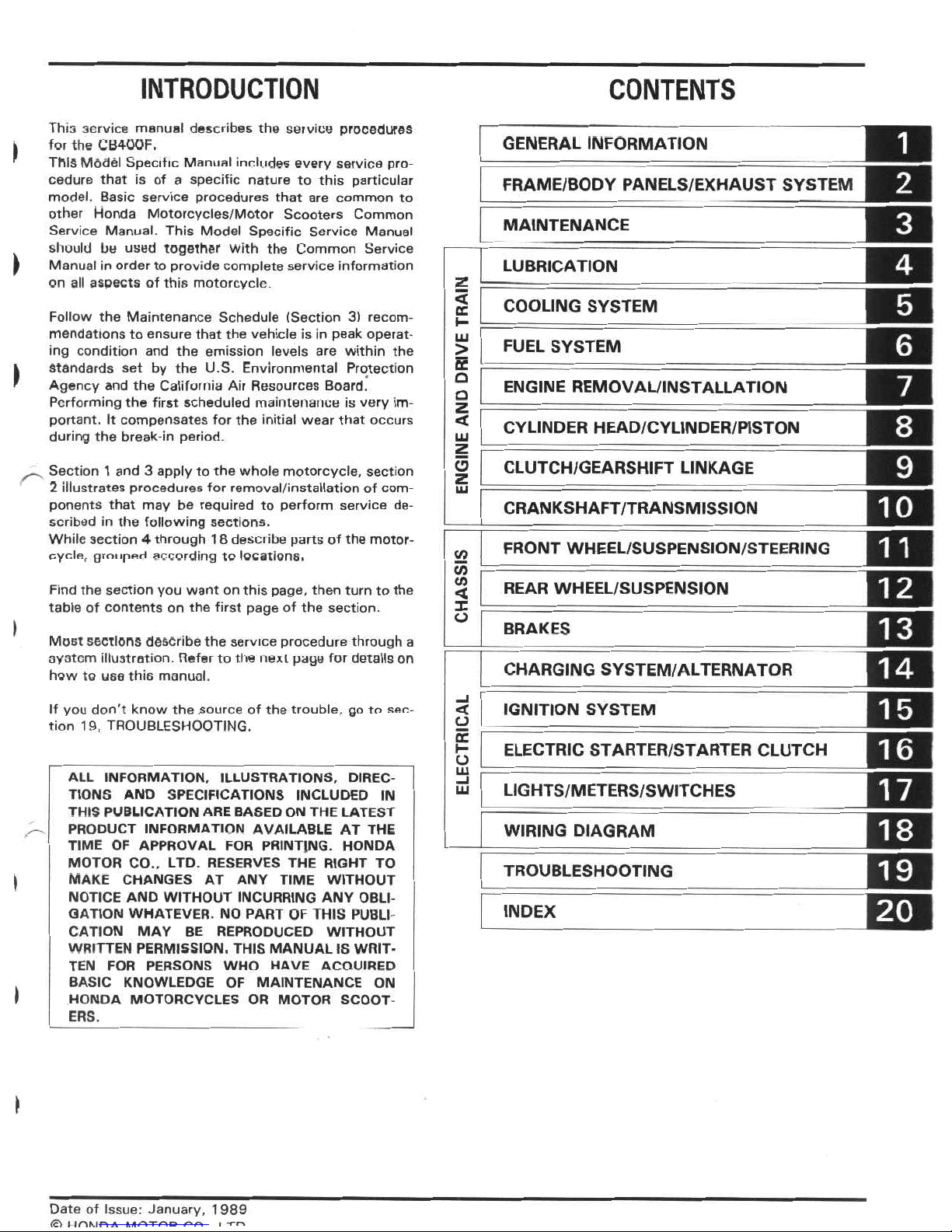
INTRODUCTION
CONTENTS
This
service
manual
describes
the
service
procedures
for
the
CB400F.
This
Model
Specific
Manual
includes
every
service
pro¬
cedure
that
is
of
a
specific
nature
to
this
particular
model.
Basic
service
procedures
that
are
common
to
other
Honda
Motorcycles/Motor
Scooters
Common
Service
Manual.
This
Model
Specific
Service
Manual
should
be
used
together
With
the
Common
Service
Manual
in
order
to
provide
complete
service
information
on
all
aspects
of
this
motorcycle
1
GENERAL
INFORMATION
I
FRAME/BODY
PANELS/EXHAUST
SYSTEM
MAINTENANCE
>
*
LUBRICATION
<
COOLING
SYSTEM
GC
Follow
the
Maintenance
Schedule
(Section
3)
recom¬
mendations
to
ensure
that
the
vehicle
is
in
peak
operat¬
ing
condition
and
the
emission
levels
are
within
the
standards
set
by
the
U.S.
Environmental
Protection
Agency
and
the
California
Air
Resources
Board.
Performing
the
first
scheduled
maintenance
is
very
im¬
portant.
It
compensates
for
the
initial
wear
that
occurs
during
the
break-in
period.
LU
FUEL
SYSTEM
>
ce
)
Q
ENGINE
REMOVAL/INSTALLATION
o
z
<
8
CYLINDER
HEAD/CYLINDER/PISTON
LU
CLUTCH/GEARSHIFT
LINKAGE
Section
1
and
3
apply
to
the
whole
motorcycle,
section
2
illustrates
procedures
for
removal/installation
of
com¬
ponents
that
may
be
required
to
perform
service
de¬
scribed
in
the
following
sections.
While
section
4
through
1
8
desetibe
parts
of
the
motor¬
cycle,
grouped
according
to
locations.
Z
LU
CRANKSHAFT/TRANSMISSION
FRONT
WHEEL/SUSPENSION/STEERING
2
C/5
C/5
REAR
WHEEL/SUSPENSION
Find
the
section
you
want
on
this
page,
then
turn
to
the
table
of
contents
on
the
first
page
of
the
section.
<
I
O
I
BRAKES
Most
sections
describe
the
service
procedure
through
a
ayatem
illustration.
Refer
to
the
next
page
for
details
on
hew
to
use
this
manual.
IF1
CHARGING
SYSTEM/ALTERNATOR
IGNITION
SYSTEM
If
you
don't
know
the
.source
of
the
trouble,
go
to
sec¬
tion
19,
TROUBLESHOOTING.
<
O
cc
ELECTRIC
STARTER/STARTER
CLUTCH
A
o
LU
ALL
INFORMATION,
ILLUSTRATIONS,
DIREC¬
TIONS
AND
SPECIFICATIONS
INCLUDED
IN
THIS
PUBLICATION
ARE
BASED
ON
THE
LATEST
PRODUCT
INFORMATION
AVAILABLE
AT
THE
TIME
OF
APPROVAL
FOR
PRINTING.
HONDA
MOTOR
CO..
LTD.
RESERVES
THE
RIGHT
TO
MAKE
CHANGES
AT
ANY
TIME
WITHOUT
NOTICE
AND
WITHOUT
INCURRING
ANY
OBLI¬
GATION
WHATEVER.
NO
PART
OF
THIS
PUBLI¬
CATION
MAY
BE
REPRODUCED
WITHOUT
WRITTEN
PERMISSION.
THIS
MANUAL
IS
WRIT¬
TEN
FOR
PERSONS
WHO
HAVE
ACQUIRED
BASIC
KNOWLEDGE
OF
MAINTENANCE
ON
HONDA
MOTORCYCLES
OR
MOTOR
SCOOT¬
ERS.
LIGHTS/METERS/SWITCHES
LU
WIRING
DIAGRAM
TROUBLESHOOTING
!
EH
INDEX
I
Date
of
Issue:
January,
1989
(51
nnMfi
A
n/inxoe
r-n
I
m
HOW
TO
USE
THIS
MANUAL
FINDING
INFORMATION
YOU
NEED
i
))
Dill
•
This
manual
is
divided
into
sections
which
cover
each
of
the
major
components
of
the
motorcycle.
To
quiGkly
find
the
section
you
are
interested
in.
the
first
page
of
each
section
is
marked
with
a
black
tab
that
lines
up
with
one
of
the
thumb
index
tabs
before
this
page.
The
first
page
of
each
section
lists
the
table
of
contents
within
the
section.
Read
the
service
information
and
troubleshooting
related
to
the
section
before
you
begin
working.
•
An
indexofthe
entire
book
is
provided
in
the
last
chapter
to
directly
locate
the
information
you
need.
I
0
JEss
vr
i
[r
-
—
1
-
1
IQ.
I
-
—
>
~
mO
I
))
NOTE
ON
THE
EXPLANATION
METHOD
OF
THIS
MANUAL
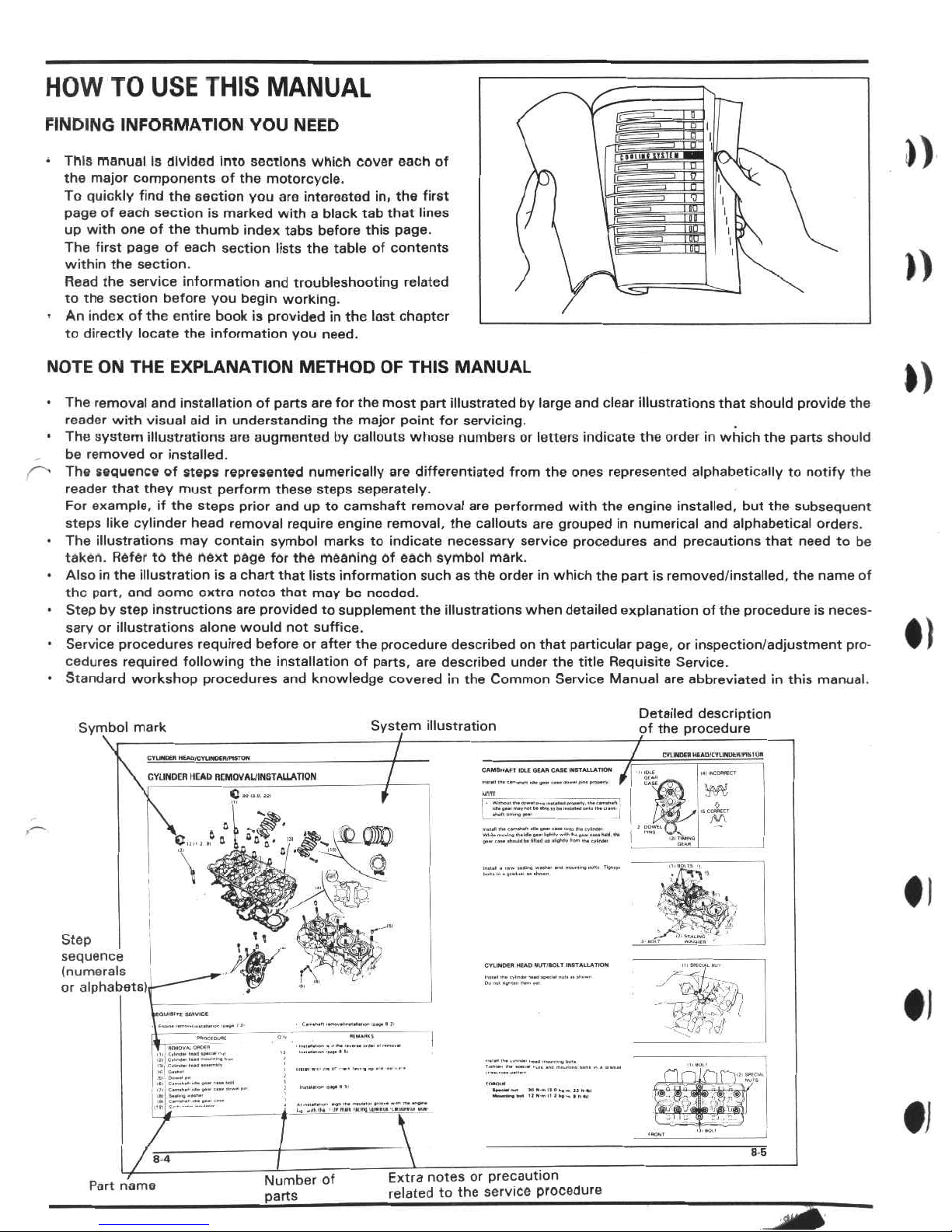
The
removal
and
installation
of
parts
are
for
the
most
part
illustrated
by
large
and
clear
illustrations
that
should
provide
the
reader
with
visual
aid
in
understanding
the
major
point
for
servicing.
The
system
illustrations
are
augmented
by
callouts
whose
numbersorletters
indicate
the
order
in
which
the
parts
should
be
removed
or
installed.
The
sequence
of
steps
represented
numerically
are
differentiated
from
the
ones
represented
alphabetically
to
notify
the
reader
that
they
must
perform
these
steps
seperately.
For
example,
if
the
steps
prior
and
up
to
camshaft
removal
are
performed
with
the
engine
installed,
but
the
subsequent
steps
like
cylinder
head
removal
require
engine
removal,
the
callouts
are
grouped
in
numerical
and
alphabetical
orders.
The
illustrations
may
contain
symbol
markstoindicate
necessary
service
procedures
and
precautions
that
needtobe
taken.
Refer
to
the
next
page
for
the
meaning
of
each
symbol
mark.
Alsointhe
illustration
is
a
chart
that
lists
information
such
as
the
orderinwhich
the
part
is
removed/installed,
the
name
of
the
part,
and
oomo
oxtra
notes
that
may
be
needed.
Step
by
step
instructions
are
providedtosupplement
the
illustrations
when
detailed
explanation
of
the
procedure
is
neces¬
sary
or
illustrations
alone
would
not
suffice.
Service
procedures
required
before
or
after
the
procedure
describedonthat
particular
page,
or
inspection/adjustment
pro¬
cedures
required
following
the
installation
of
parts,
are
described
under
the
title
Requisite
Service.
Standard
workshop
procedures
and
knowledge
covered
in
the
Common
Service
Manual
are
abbreviated
in
this
manual.
•)
Detailed
description
of
the
procedure
—
CAMSHAF
T
IDLE
GIAN
CASE
INSTALLATION
/
.
,
,
l0l£
W
0t<kn
-M-,
System
illustration
Symbol
mark
CTUNDEH
HEAPlCYCINPCHiPtSTOW
CYLINDER
MEAD
RCMOVAUINGTALLATION
m
■a
•
gau
m«Y
'ÿol
b*
obit
10
«•
innatad
cole
i
""ÿ"“I
N.,
jW
b
.....
.».*t
kirn*
iho
camofidiT
«iu
gnu
CBM
unio
tKo
cvlnoo1
*1.1.
mw.lr*
lb.
iA.
gw
UfMv
~*K
IK.
B*.
fllB
KoM
1M
9.0
rju
diiKidboHllod
u»
0»tF»V
from
iKo
eytAdM
!
\l
.
J
TIVI
#1
V
i
■
str
Step
sequence
(numerals
or
alphabets).
*-M£T
t
5
|
-
CVUNOM
MEAD
NUT'SOIT
INSTALLATION
-ÿmu
nxrrr
—
•I
MtnrtDi.Al
111!
C.loyrtr
twofl
Iptooi
nul
(Zl
C»i«i»
b*od
<•*'
On
XTr-“
:
<||
Sodo-J
1.MTBI
*
At
.AtloNOI-v.
MgK
IKO
..lAol.M
0..W..O
»«0>
IKo
on«no
I
U
■UI’IMW
'IUWIWNW
1WIW
MJf
>1—
xm.noif.
1)1101
MM»|WI
1
1
NIKIIi
Kf
-*
ln«l
•1
8
5
8
4
Extra
notes
or
precaution
related
to
the
service
procedure
Number
of
parts
_
Part
name
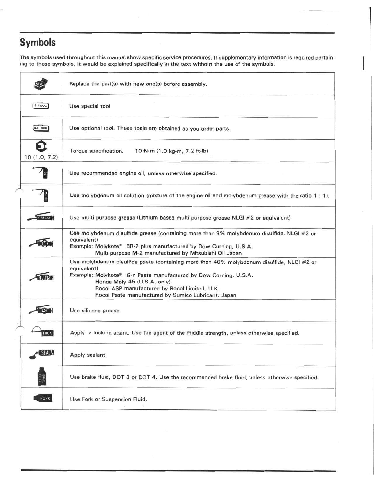
Symbols
The
symbols
used
throughout
this
manual
show
specific
service
procedures.
If
supplementary
information
is
required
pertain¬
ing
to
these
symbols,
it
would
be
explained
specifically
in
the
text
without
the
use
of
the
symbols.
Replace
the
pait(s)
with
new
one(s)
before
assembly.
[s
TOOL
I
Use
special
tool
Use
optional
tool.
These
tools
are
obtained
as
you
order
parts.
0
Torque
specification.
1
0
M-m
(1.0
kg-m,
7.2
ft-lb)
10
(1.0,
7.2)
"1
Use
recommended
engine
oil,
unless
otherwise
specified.
‘1
Use
molybdenum
oil
solution
(mixture
of
the
engine
oil
and
molybdenum
grease
with
the
ratio
1:1).
Use
multi-purpose
grease
(Lithium
based
multi-purpose
grease
NLGI
#2
or
equivalent)
Use
molybdenum
disulfide
grease
(containing
more
than
3%
molybdenum
disulfide,
NLGI
#2
or
equivalent)
Example:
Molykote®1
BR-2
plus
manufactured
by
Duw
Corning,
U.S.A.
Multi-purpose
M-2
manufactured
by
Mitsubishi
Oil
Japan
Use
molybdenum
disulfide
paste
(containing
more
than
40%
molybdenum
disulfide,
NLGI
#2
or
equivalent)
Fvample:
Molykote®
G-n
Paste
manufactured
by
Dow
Corning,
U.S.A.
Honda
Moly
45
(U.S.A.
only)
Rocol
ASP
manufactured
by
Rocol
Limited,
U.K.
Rocol
Paste
manufactured
by
Sumico
Lubricant,
Japan
Use
silicone
grease
Apply
a
locking
agent.
Use
the
agent
of
the
middle
strength,
unless
otherwise
specified.
Apply
sealant
Use
brake
fluid,
DOT
3
or
DOT
4.
Use
the
recommended
brake
fluid,
unless
otherwise
specified.
*42
Use
Fork
or
Suspension
Fluid.
1
.
GENERAL
INFORMATION
»
1
GENERAL
SAFETY
MODEL
IDENTIFICATION
SPECIFICATIONS
TORQUE
VALUES
TOOLS
1-1
LUBRICATION
AND
SEAL
POINTS
1
-3
CABLE
AND
HARNESS
ROUTING
1
-4
EMISSION
CONTROL
SYSTEMS
1-18
1-19
1
25
1-14
EMISSION
CONTROL
INFORMATION
LABELS
(U.S.A.
Only)
»
1-28
1-16
GENERAL
SAFETY
»
Carbon
Monoxide
If
the
engine
must
be
running
to
do
some
work,
make
sure
the
area
is
well
ventilated.
Never
run
the
engine
in
an
en¬
closed
area.
Used
Engine/Transmission
Oil
AWARNING
•
Used
engine
oil
(or
transmission
oil
in
two-strokes)
may
cause
skin
cancer
if
repeatedly
left
in
contact
with
the
skin
for
prolonged
periods.
Although
this
is
unlikely
unless
you
handle
used
oil
on
a
daily
basis,
it
is
still
advisable
to
thoroughly
wash
your
hands
with
soap
and
water
as
soon
as
possible
after
handling
used
oil.
KEEP
OUT
OF
REACHOFCHILDREN.
AWARNING
*
The
exhaust
contains
poisonous
carbon
monoxide
gaa
that
can
cause
loss
of
cunsciuusness
and
may
leadtodeath.
Run
the
engine
in
an
open
area
or
with
an
exhaust
evacua¬
tion
system
in
an
enclosed
area.
Brake
Dust
Never
use
an
air
hose
or
dry
brush
to
clean
brake
assemb¬
lies.
Use
an
OSHA-approved
vacuum
cleaner
or
alternate
method
approved
by
OSHA,
designed
to
minimize
the
hazard
caused
by
airborne
asbestos
fibers.
Gasoline
Work
in
a
well
ventilated
area.
Keep
cigarettes,
flames
or
sparks
away
from
the
work
area
or
where
gasoline
is
stored.
>
AWARNING
AWARNING
*
Inhaled
asbestos
fibers
have
been
found
to
cause
respiratory
disease
and
cancer.
•
Gasoline
is
extremely
flammable
and
is
explosive
under
certain
conditions.
KEEP
OUT
OF
REACH
OF
CHILDREN.
Brake
Fluid
CAUTION
Hot
Components
•
Spilling
fluid
on
painted,
plastic
or
rubber
parts
will
damage
them.
Placeaclean
shop
towel
over
these
parts
whenever
the
system
is
serviced.
KEEP
OUT
OF
REACH
OF
CHILDREN.
AWARNING
•
Engine
and
exhaust
system
parts
become
very
hot
and
remain
hot
for
some
time
after
the
engine
is
run.
Wear
Insulated
gloves
or
wait
until
the
engine
and
exhaust
system
have
cooled
before
handling
these
parts.
I
I
>
GENERAL
INFORMATION
Coolant
Under
some
conditions,
the
ethylene
glycolinengine
cool¬
ant
is
combustible
and
Its
flame
is
not
visible.
If
the
ethyl¬
ene
glycol
does
ignite,
you
will
not
see
any
flame,
but
you
can
be
burned.
Nitrogen
Pressure
For
shock
absorbers
with
a
gas-filled
reservoir:
4
A
WARNING
I
*
Use
only
nitrogen
to
pressurize
the
shock
absorber.
The
use
of
an
unstable
gas
can
cause
a
fire
or
explo¬
sion
resulting
in
serious
injury.
•
The
shock
absorber
contains
nitrogen
under
high
pressure.
Allowing
fire
or
heat
near
the
shock
ab¬
sorber
could
lead
to
an
explosion
that
could
result
in
serious
injury.
•
Failuretorelease
the
pressure
from
a
shock
absorber
before
disposing
of
it
may
lead
to
a
possible
explo¬
sion
and
serious
injury
if
it
is
heated
or
pierced.
AWARNING
*
Avoid
spilling
engine
coolantonthe
exhaust
system
or
engine
parts
They
may
be
hot
enough
to
cause
the
coolant
to
ignite
and
burn
without
a
visible
flame.
•
Coolant
(ethylene
glycol)
can
cause
some
skin
irrita¬
tion
and
is
poisonous
if
swallowed.
KEEP
OUT
OF
REACH
OF
CHILDREN.
•
Do
not
remove
the
radiator
cap
when
the
engine
is
hot.
The
coolant
is
undei
pressure
and
could
scald
you.
.
•
Keep
hands
and
clothing
away
from
the
cooling
fan,
as
it
starts
automatically.
(
To
prevent
the
possibility
of
an
explosion,
release
the
ni¬
trogen
by
pressing
the
valve
core.
Then
remove
the
valve
stem
from
the
shock
absorber
reservoir.
Dispose
of
the
oil
in
a
manner
acceptable
to
the
Environmental
Protection
Agency
(fcPA).
I
If
it
contacts
your
skin,
wash
the
affected
areas
immedi¬
ately
with
soap
and
water.
If
it
contacts
your
eye6,
flush
them
thoroughly
with
fresh
water
and
get
immediate
medi¬
cal
attention.
If
it
is
swallowed,
the
victim
must
be
forced
to
vomit
then
rinse
mouth
and
throat
with
fresh
water
before
obtaining
medical
attention.
Becauseofthese
dan¬
gers,
always
Store
coolant
in
a
safe
place,
away
from
the
reach
of
children.
Before
disposal
of
the
shock
absorber,
release
the
nitrogen
by
pressing
the
valve
core.
Then
remove
the
valve
stem
from
the
shock
absorber.
Battery
Hydrogen
Gas
&
Electrolyte
AWARNING
•
The
battery
gives
off
explosive
gases;
keep
sparks,
flames
and
cigarettes
away.
Provide
adequate
venti¬
lation
when
charging.
•
The
battery
contains
sulfuric
acid
(electrolyte).
Con¬
tact
with
skin
or
eyes
may
cause
severe
bums.
Wear
protective
clothing
and
a
face
shield.
If
electrolyte
gets
on
your
skin,
flush
with
water.
—
If
electrolyte
gets
in
your
eyes,
flush
with
water
for
at
least
15
minutes
and
call
a
physician.
•
Electrolyte
is
poisonous.
—
If
swallowed,
drink
large
quantities
of
water
or
milk
and
follow
with
milk
of
magnesia
or
vegeta¬
ble
oil
and
call
a
physician.
KEEP
OUTOFREACH
OF
CHILDREN.
♦
I
♦
i
♦i
1-2

GENERAL
INFORMATION
MODEL
IDENTIFICATION
I
O
0
D
0,
c
o.
'CbJ
f0
Vÿ\
(1)
FRAME
SERIAL
NUMBER
\
0
L
I
The
frame
serial
number
is
stamped
on
the
right
side
of
the
steering
head.
(2)
ENGINE'SERIAL
NUMBER
c
V
m
\
\
o
V/
4$
I
ft
s.
\r\
(3)
VEHICLE
IDENTIFICATION
NUMBER
'
rs,
o.
The
engine
serial
number
is
stamped
on
the
right
side
of
the
crankcase.
The
Vehicle
Identification
Number
(VIN)
is
located
on
the
safety
certification
label
on
the
right
side
of
the
frame
tube.
I
(4)
CARBURETOR
IDENTIFICATION
NUMBER
V
l\
y
(CM
4L
>
\
&
37
N
Sm
__
_
(5)
COLOR
CODE
LABEL
>
The
carburetor
identification
number
is
on
the
rear
side
of
oach
carburetor.
The
color
code
label
is
attached
on
the
left
frame
tube
under
the
seat.
When
ordering
a
color
coded
part,
always
specify
its
designated
color
code.
GENERAL
INFORMATION
SPECIFICATIONS
Gi
4
ITEM
SPECIFICATIONS
2,035
mm
(80.
1
in)
705
mm
(27.8
in)
1,025
mm
(40.4
in)
1
,370
mm
(53.9
in)
775
mm
(30.5
in)
335
mm
(13.2
in)
130
mm
(5.1
in)
170
kg
(375
lbs)
183
kg
(403
lbs)
1
57
kg
(347
lbs)
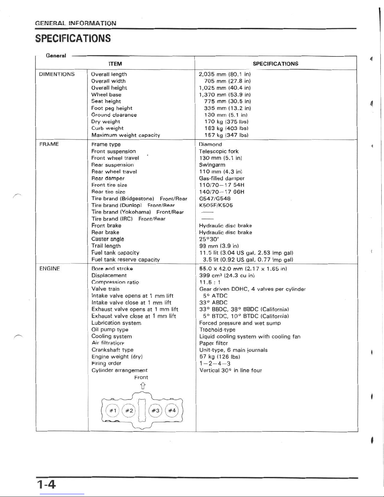
Overall
length
Overall
width
Overall
height
Wheel
base
Seat
height
Foot
peg
height
Ground
clearance
Dry
weight
Curb
weight
Maximum
weight
capacity
DIMENTIONS
4
FRAME
Diamond
Telescopic
fork
1
30
mm
(5.1
in)
Swingarm
110
mm
(4.3
in)
Gas-filled
damper
1
10/70-17
54H
140/70-17
66H
G547/G548
K505F/K505
Frame
type
Front
suspension
Front
wheel
travel
Rear
suspension
Rear
wheel
travel
Rear
damper
Front
tire
size
Rear
tire
size
Tire
brand
(Bridgestone)
Front/Rear
Tire
brand
(Dunlop)
Front/Rear
Tire
brand
(Yokohama)
Front/Rear
Tire
brand
(IRC)
Front/Rear
Front
brake
Rear
brake
Caster
angle
Trail
length
Fuel
tank
capacity
Fuel
tank
reserve
capacity
«
Hydraulic
disc
brake
Hydraulic
disc
brake
25u30’
99
mm
(3.9
in)
11
.5
lit
(3.04
US
yal,
2.53
Imp
gal)
3.5
lit
(0.92
US
gal,
0.77
Imp
gal)
(
ENGINE
Bore
and
stroke
Displacement
Compression
ratio
Valve
train
Intake
valve
opens
at
1
mm
lift
Intake
valve
close
at
1
mm
lift
Exhaust
valve
opens
at
1
mm
lift
Exhaust
valve
close
at
1
mm
lift
Lubrication
system
Oil
pump
type
Cooling
system
Air
filtration*
Crankshaft
type
Engine
weight
(dry)
Firing
order
Cylinder
arrangement
Front
55.0
x
42.0
mm
(2.17
x
1.65
in)
399
cm3
(24.3
cu
in)
11.6
:
1
Gear
driven
DOHC,
4
valves
per
cylinder
5°
ATDC
33°
ABDC
33°
BBDC,
38°
BBDC
(California)
5°
BTDC,
10°
BTDC
(California)
Forced
pressure
and
wet
sump
Trochoid
type
Liquid
cooling
system
with
cooling
fan
Paper
filter
Unit-type,
6
main
journals
57
kg
(126
lbs)
1
—2—4—3
Vertical
30°
in
line
four
»
I
I
1-4
GENERAL
INFORMATION
General
(Cont'd)
ITEM
SPECIFICATIONS
I
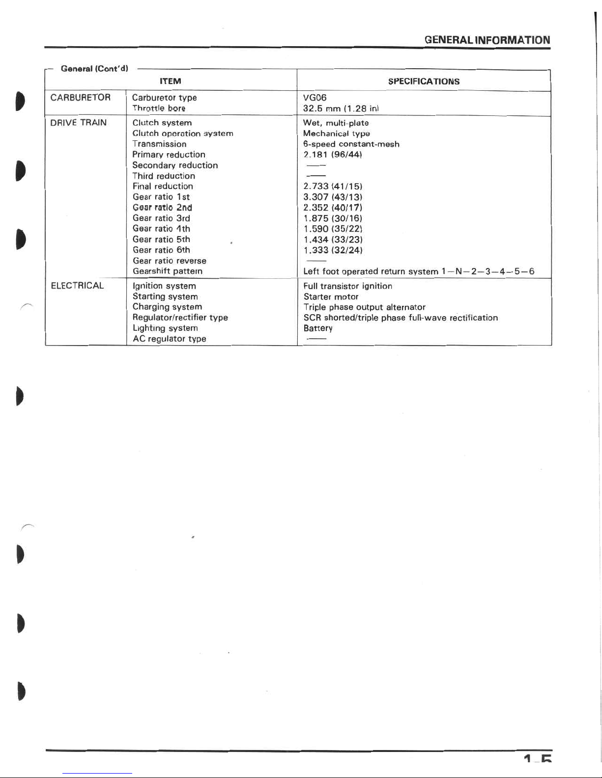
CARBURETOR
Carburetor
type
Throttle
bore
VG06
32.
6
mm
(1
.28
in)
DRIVE
TRAIN
Clutch
system
Clutch
oporation
3y3tem
Transmission
Primary
reduction
Secondary
reduction
Third
reduction
Final
reduction
Gear
ratio
1st
Gear
ratio
2nd
Gear
ratio
3rd
Gear
ratio
4th
Gear
ratio
5th
Gear
ratio
6th
Gear
ratio
reverse
Gearshift
pattern
Wet,
multi-plate
Mechanical
type
6-speed
constant-mesh
2.181
(96/44)
»
2.733
(41/15)
3.307
(43/13)
2.352
(40/17)
1.875
(30/16)
1.590
(35/22)
1.434
(33/23)
1.333
(32/24)
»
Left
foot
operated
return
system
1—
N
—
2
—
3—
4—
5
—
6
Full
transistor
ignition
Starter
motor
Triple
phase
output
alternator
SCR
shorted/triple
phase
full-wave
rectification
Battery
ELECTRICAL
Ignition
system
Starting
system
Charging
system
Regulator/rectifier
type
Lighting
system
AC
regulator
type
*
>
)
>
1
E

GENERAL
INFORMATION
Unit:
mm
(in)
Lubrication
Standard
Service
limit
Item
I
2.9
e
(3.06
US
qt,
2.55
Imp
qt)
3.5
t
(3.70
US
qt,
3.08
Imp
qt)
3.1
t
(3.28
US
qt,
2.73
Imp
qt)
HONDA
4-stroke
oil
or
equivalent.
API
service
classification
SEorSF.
Engine
oil
capacity
at
draining
at
disassembly
at
oil
filter
change
Recommended
engine
oil
Q||_
VISCOSITIES
I
The
viscosities
shown
in
the
chart
may
be
used
when
the
average
temperature
in
your
riding
area
is
within
the
indicated
range.
»
»
o
20
40
60
80
IOO
*F
I
-20
-10
Oil
pressure
at
oil
pressure
switch
Oil
pump
roter
tip
clearance
©
body
clearance
@
end
clearance
(3)
m
fO
50
10
*C
O
490
kPa
(5
kg/cm2,71psi)
0.10
(0.004)
0.15-0.22
(0.006-0.009)
0.02-0.07
(0.001-0.003)
0.15
(0.006)
0.35
(0.014)
0.10
(0.004)
<3>
©y
®
/
-
Fuel
system
-
Carburetor
identification
number
VG06B
VG06C
#105
I
(California)
Main
jet
(High
altitude)
(2,
3)
(1,
4)
(Front)
(Rear)
Slow
jet
Jet
needle
crip
position
rilot
screw
initial
opening
#35
2-1/4
turns
out
2-1/2
turns
out
1
turn
out
1/2
turn
in
from
initial
opening
(California)
Pilnt
screw
adjustment
final
opening
Pilot
screw
high
altitude
adjustment
Air
screw
initial
opening
I
(California)
Air
screw
high
altitude
adjustment
Float
level
Carburetor
vacuum
difference
Base
caibureior
(For
carburetor
synchronization)
Idle
speed
8.0
(0.31)
Within
30
mmHg
(1.2
inHg)
No.2carburetor
1
,300
±100
rpm
1
,400
±100
rpm
2-6
(0.08-0.24)
(California)
1
Throttle
grip
free
play
Accelerator
pump
clearance
Secondary
air
supply
system
Air
injection
control
valve
vacuum
pressure
Reed
valves
are
built
into
the
ASV
360
mmHg
(14.2
inHg)
1-6
GENERAL
INFORMATION
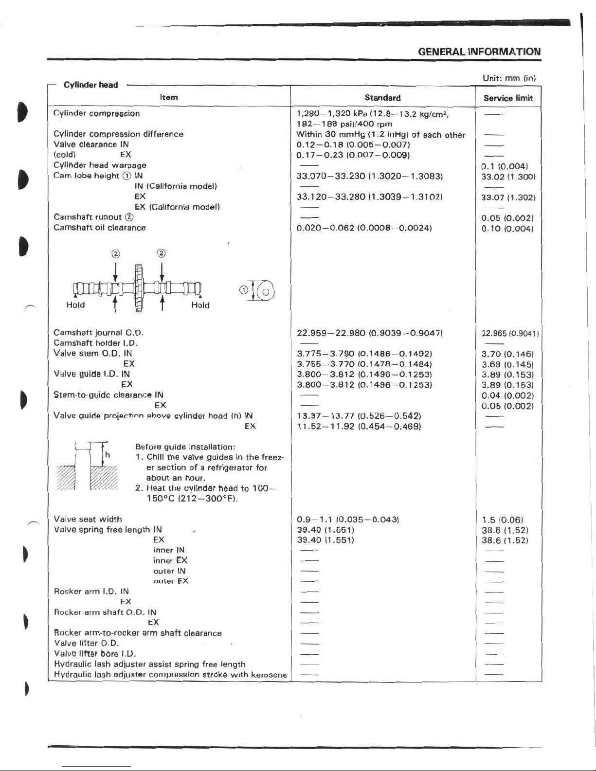
Unit:
mm
(in)
Cylinder
head
Item
Standard
Service
limit
ft
Cylinder
compression
1,280-1,320
kPa
(12.8-13.2
kg/cm2,
182-188
psi)/400
rpm
Within
30
mmHg
(1.2
inHg)
of
each
other
0.12-0.18
(0.005-0.007)
0.17-0.23
(0.007-0.009)
Cylinder
compression
difference
Valve
clearance
IN
(cold)
Cylinder
head
warpage
Cam
lobe
height
©
IN
EX
0.1
(0.004)
33.02
(1.300)
ft
33.070-33.230
(1.3020-1.3083)
IN
(California
model)
EX
33.120-33.280
<
1
.3039—
1
.3102)
33.07
(1.302)
EX
(California
model)
Camshaft
runout
©
Camshaft
oil
clearance
0.05
(0.002)
0.10
(0.004)
0.020-0.062
(0.0008-0.0024)
ft
©
J
i
JBCBHP
®E°)
t
t
Hold
Hold
Camshaft
journal
O.D.
Camshaft
holder
I.D.
Valve
stem
O.D.
IN
22.959-22.980
(0.9039-0.9047)
22.965
(0.9041)
3.775-3.790
(0.1486-0.1492)
3.755-3.770
(0.1478-0.1484)
3.800-3.812
(0.1496-0.1253)
3.800-3.812
(0.1496-0.1253)
3.70
(0.146)
3.69
(0.145)
3.89
(0.153)
3.89
(0.153)
0.04
(0.002)
0.05
(0.002)
EX
Valve
guide
I.D.
IN
EX
>
Stem-to-guidc
clearance
IN
EX
Valve
guide
projection
above
cylinder
head
(h)
IN
13.37-13.77
(0.526-0.542)
1
1.52-
1
1
.92
(0.454-0.469)
EX
Before
guide
installation:
1
.
Chill
the
valve
guides
in
the
freez¬
er
section
of
a
refrigerator
for
about
an
hour.
2.
Heat
the
cylinder
head
to
100—
1
50°C
(21
2
—
300°F).
h
i
Valve
seat
width
Valve
spring
free
length
IN
0.9-1.
1
(0.035-0.043)
39.40
(1.551)
39.40
(1.551)
1.5
(0.06)
38.6
(1.52)
38.6
(1.52)
EX
)
inner
IN
inner
EX
outer
IN
outei
EX
Rocker
arm
I.D.
IN
EX
Rocker
arm
shaft
O.D.
IN
EX
Rocker
arm-to-rocker
arm
shaft
clearance
Valve
lifter
O.D.
Valve
lifter
bcre
I.D.
Hydraulic
lash
adjuster
assist
spring
free
length
Hydraulic
lash
adjuster
compiession
stroke
with
kerosene
GENERAL
INFORMATION
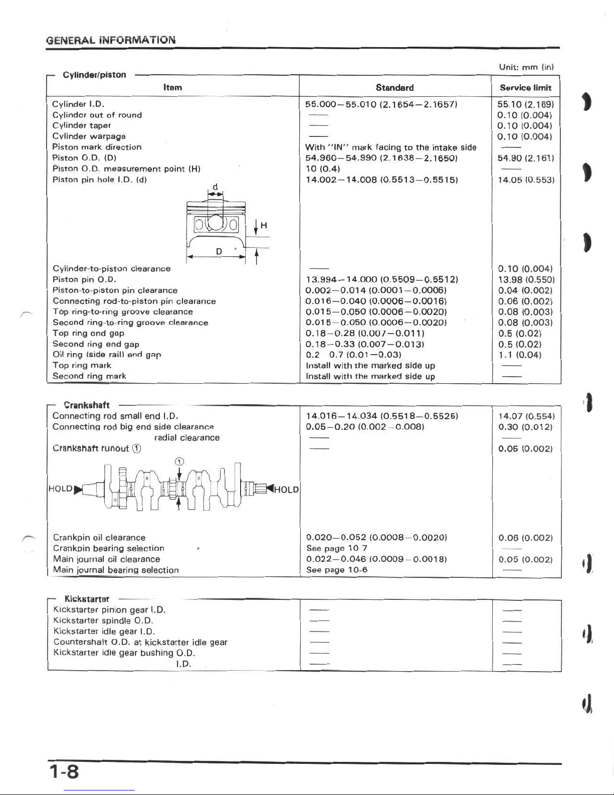
Unit:
mm
(in)
Cylinder/piston
Item
Standard
Service
limit
Cylinder
I.D.
Cylinder
out
of
round
Cylinder
taper
Cylinder
warpage
Piston
mark
direction
Piston
O.D.
(D)
Piston
O.D.
measurement
point
(H)
Piston
pin
hole
I.D.
(d)
55.000-55.010
(2.1654-2.1657)
55.10
(2.169)
0.10
(0.004)
0.10
(0.004)
0.10
(0.004)
With
"IN"
mark
facing
to
the
intake
side
54.960-54.990
(2.1638-2.1650)
10
(0.4)
14.002-14.008
(0.5513-0.5515)
54.90
(2.161)
I
14.05
(0.553)
d
0O5II
I
D
Cylinder-to-piston
clearance
Piston
pin
O.D.
Piston-to-piston
pin
clearance
Connecting
rod-to-piston
pin
clearance
Top
ring-to-ring
groove
clearance
Second
ring-to-ring
groove
clearance
Top
ring
end
gap
Second
ring
end
gap
Oil
ring
(side
rail)
end
gap
Top
ring
mark
Second
ring
mark
0.10
(0.004)
13.98
(0.550)
0.04
(0.002)
0.06
(0.002)
0.08
(0.003)
0.08
(0.003)
0.5
(0.02)
0.5
(0.02)
1.1
(0.04)
13.994-14
000
(0.5509-0.5512)
0.002-0.014
(0.0001-0.0006)
0.016-0.040
(0.0006-0.0016)
0.015-0.050
(0.0006-0.0020)
0.015
0.050
(0.0006-0.0020)
0.18-0.28
(0.00/-0.011)
0.18-0.33
(0.007-0.013)
0.2
0.7(0.01-0.03)
Install
with
the
marked
side
up
Install
with
the
marked
side
up
I
i
-
Crankshaft
-
-
Connecting
rod
small
end
I.D.
Connecting
rod
big
end
side
clearance
radial
clearance
14.016-14.034
(0.5518-0.5525)
0.05-0.20(0.002
0.008)
14.07
(0.554)
0.30
(0.012)
Crankshaft
runout
(jj
0.05
(0.002)
©
I
/1
O
H0LDÿ[_
UNHOLD
t
Crankpin
oil
clearance
Crankpin
bearing
selection
Main
journal
oil
clearance
Main
journal
bearing
selection
0.020-0.052
(0.0008-0.0020)
See
page
10
7
0.022-0.046
(0.0009-0.0018)
See
page
10-6
0.06
(0.002)
')
0.05
(0.002)
-
Kickstartor
--
--
Kickstarter
pinion
gear
I.D.
Kickstarter
spindle
O.D.
Kickstarter
idle
gear
I.D.
Countershaft
O.D.
at
kickstarter
idle
gear
Kickstarter
idle
gear
bushing
O.D.
'1
I.D.
4
1-8
GENERAL
INFORMATION
Unit:
mm
(in)
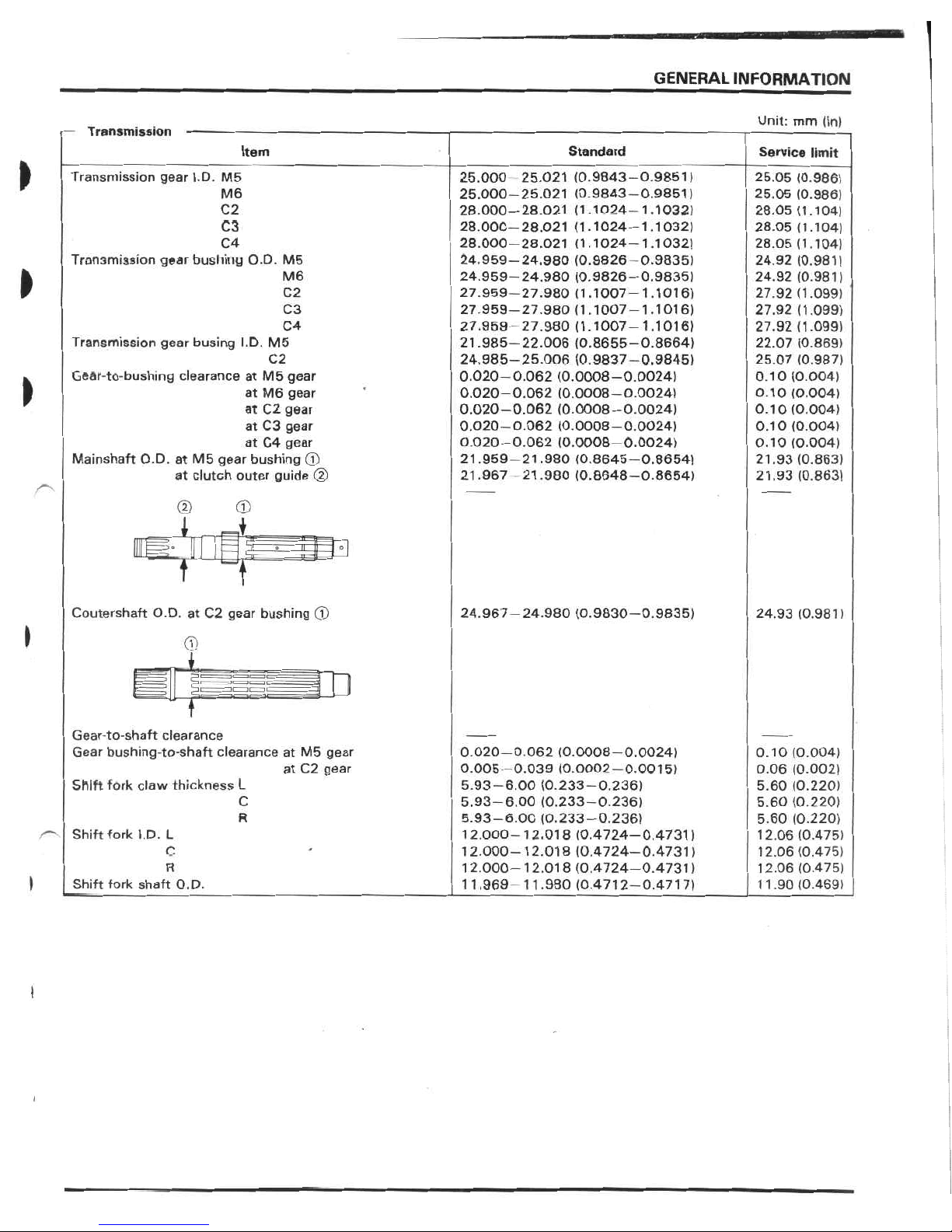
Transmission
Item
Standard
Service
limit
►
Transmission
gear
I.D.
M5
25.000
25.021
(0.9843-0.9851)
25.000-25.021
(0.9843-0.9851)
28.000-28.021
(1.1024-1.1032)
28.000-28.021
(1.1024-1.1032)
28.000-28.021
(1.1024-1.1032)
24.959-24,980
(0.9826
-0.9835)
24.959-24.980
(0.9826-0.9835)
27.959-27.980
(1.1007-1.1016)
27.959-27.980
(1.1007-1.1016)
27.959
27.980(1.1007-1.1016)
21.985-22.006
(0.8655-0.8664)
24.985-25.006
(0.9837-0.9845)
0.020-0.062
(0.0008-0.0024)
0.020-0.062
(0.0008-0.0024)
0.020-0.062
(0.0008-0.0024)
0.020-0.062
(0.0008-0.0024)
0.020-0.062
(0.0008-0.0024)
21.959-21.980
(0.8645-0.8654)
21.967
-21.980
(0.8648-0.8654)
25.05
(0.986)
25.05
(0.986)
28.05
(1.104)
28.05
(1.104)
28.05
(1.104)
24.92
(0.981)
24.92
(0.981)
27.92
(1.099)
27.92
(1.099)
27.92
(1.099)
22.07
(0.869)
25.07
(0.987)
0.10
(0.004)
0.10
(0.004)
0.10
(0.004)
0.10
(0.004)
0.10
(0.004)
21.93
(0.863)
21.93
(0.863)
M6
C2
C3
C4
Transmission
gear
bushing
O.D.
M5
M6
C2
C3
C4
Transmission
gear
busing
I.D.
M5
C2
Gear-to-bushing
clearance
at
M5
gear
at
M6
gear
at
C2
gear
at
C3
gear
at
C4
gear
Mainshaft
O.D.
at
M5
gear
bushing
©
at
clutch
outer
guide
©
>
©
©
1
A
mrÿm
i
Coutershaft
O.D.
at
C2
gear
bushing
©
24.967-24.980
(0.9830-0.9835)
24.93
(0.981)
©
I
T
Gear-to-shaft
clearance
Gear
bushing-to-shaft
clearanceatM5
gear
at
C2
gear
0.020-0
062
(0.0008-0.0024)
0.005-0.039
(0.0002-0.0015)
5.93-6.00
(0.233-0.236)
5.93-6.00
(0.233-0.236)
5.93-6.00
(0.233-0.236)
12.000-12.018
(0.4724-0.4731)
12.000-12.018
(0.4724-0.4731)
12.000-12.018
(0.4724-0.4731)
11.969
11.980(0.4712-0.4717)
0.10
(0.004)
0.06
(0.002)
5.60
(0.220)
5.60
(0.220)
5.60
(0.220)
12.06
(0.475)
12.06
(0.475)
12.06
(0.475)
11.90
(0.469)
Shift
fork
claw
thickness
L
C
R
Shift
fork
I.D.
L
C
R
I
Shift
fork
shaft
O.D.
I
i
GENERAL
INFORMATION
Unit:
mm
(in)
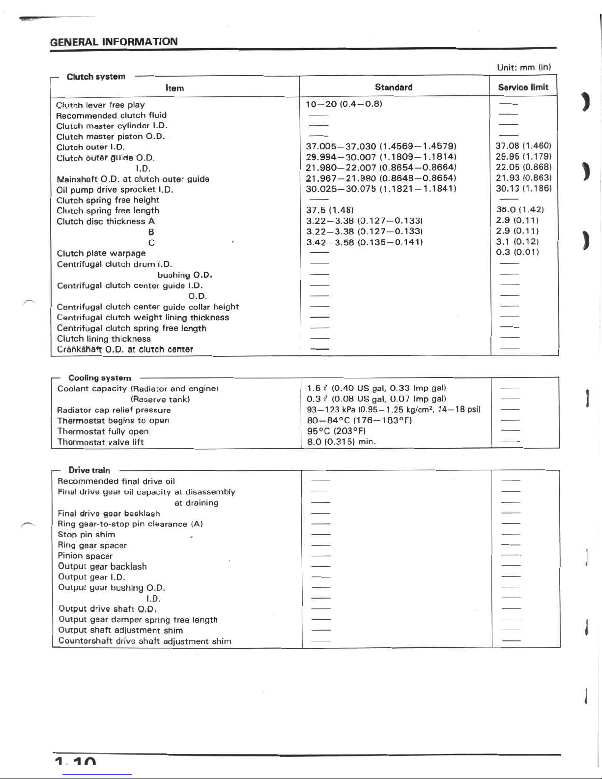
Clutch
system
Service
limit
Item
Standard
>
10-20
(0.4—
0.8)
Clutch
lever
free
play
Recommended
clutch
fluid
Clutch
master
cylinder
I.D.
Clutch
master
piston
O.D.
Clutch
outer
I.D.
Clutch
outer
guide
O.D.
37.005-37.030
(1.4569-1.4579)
29.994-30.007
(1.1809-1.1814)
21.980-22.007
(0.8654-0.8664)
21.967-21.980
(0.8648-0.8654)
30.025-30.075
(1.1821-1.1841)
37.08
(1.460)
29.95
(1.179)
22.05
(0.868)
21.93
(0.863)
30.13
(1.186)
)
I.D.
Mainshaft
O.D.
at
clutch
outer
guide
Oil
pump
drive
sprocket
I.D.
Clutch
spring
free
height
Clutch
spring
free
length
Clutch
disc
thickness
A
36.0
(1.42)
2.9
(0.11)
2.9
(0.11)
3.1
(0.12)
0.3
(0.01)
37.5
(1.48)
3.22-3.38
(0.127-0.133)
3.22-3.38
(0.127-0.133)
3.42-3.58
(0.135-0.141)
B
)
C
Clutch
plate
warpage
Centrifugal
clutch
drum
I.D.
bushing
O.D.
Centrifugal
clutch
center
guide
I.D.
O.D.
Centrifugal
clutch
center
guide
collar
height
Centrifugal
clutch
weight
lining
thickness
Centrifugal
clutch
spring
free
length
Clutch
lining
thickness
Crankshaft
O.D.
at
clutch
center
-
Cooling
system
-
Coolant
capacity
(Radiator
and
engine)
(Reserve
tank)
Radiator
cap
relief
pressure
Thermostat
begins
to
open
Thermostat
fully
open
Thermostat
valve
lift
1
.5
(
(0.40
US
gal,
0.33
Imp
gal)
0.3
f
(0.08
US
gal,
0.07
Imp
gal)
93-123
kPa
(0.95-1.25
kg/cm2,
14-18
psi)
80—
04"C
(1
76—
1
83°F)
95°C
(203°F)
8.0
(0.315)
min.
I
-
Drive
train
-
Recommended
final
drive
oil
Filial
diive
yeai
uil
capacityatdisassembly
at
draining
Final
drive
gear
backlash
Ring
gear-to-stop
pin
clearance
(A)
Stop
pin
shim
Ring
gear
spacer
Pinion
spacer
Output
gear
backlash
Output
gear
I.D.
Output
gear
bushing
O.D.
I
I.D.
Output
drive
shaft
O.D.
Output
gear
damper
spring
free
length
Output
shaft
adjustment
shim
Countershaft
drive
shaft
adjustment
shim
I
J
1
_1
A
GENERAL
INFORMATION
Unit:
mm
(in)
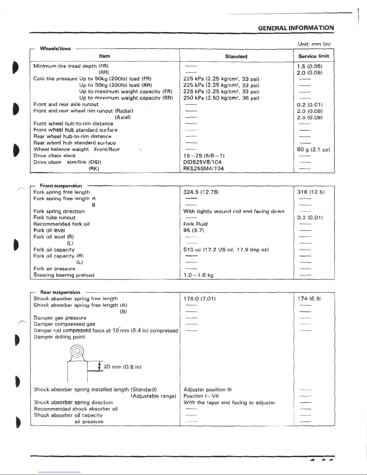
Wheeis/tires
Service
limit
Item
Standard
ft
Minimum
tire
tread
depth
(FR)
(HR)
Cold
tire
pressure
Up
to
90kg
(2001b)
load
(FR)
Up
to
90kg
(2001b)
load
(RR)
Up
to
maximum
weight
capacity
(FR)
Up
to
maximum
weight
capacity
(RR)
1.B
(0.06)
2.0
(0.08)
225
kPa
(2.25
kg/cm2,
33
psi)
225
kPa
(2.25
kg/cm2,
33
psi)
225
kPa
(2.25
kg/cm2,
33
psi)
250
kPa
(2.50
kg/cm2,
36
psi)
Front
and
rear
axle
runout
ft
0.2
(0.01)
2.0
(0.08)
2.0
(0.08)
Front
and
rear
wheel
rim
runout
(Radial)
(Axial)
Front
wheel
hub-to-rim
distance
Front
wheel
hub
standard
surface
Rear
wheel
hub-to-rim
distance
Rear
wheel
hub
standard
surface
Wheel
balance
weight
Front/Rear
Drive
chain
slack
Drive
chain
size/link
(DID)
(RK>
ft
60
g
(2.1
oz)
15-25
(5/8-1)
DID525V8/1
04
RK525SM4/1
04
-
Front
suspension
-
Fork
spring
free
length
Fork
spring
free
length
A
318
(12.5)
324.5
(12.78)
B
Fork
spring
direction
Fork
tube
runout
Recommended
fork
oil
Furk
oil
level
Fork
oil
level
(R)
With
tightly
wound
coil
end
facing
down
0.2
(0.01)
Fork
Fluid
95
(3.7)
»
(L)
510
cc
(17.2
US
oz,
17.9
Imp
oz)
Fork
oil
capacity
Fork
oil
capacity
(R)
(L)
Fork
air
pressure
Steering
bearing
preload
1.0-
1.6
kg
-
Rear
suspension
-
Shock
absorber
spring
free
length
Shock
absorber
spring
free
length
(A)
174
(6.9)
170.0
(7.01)
(B)
Damper
gas
pressure
Damper
compressed
gas
Dampei
lud
compressed
force
at
10
mm
(0.4
in)
compressed
Damper
drilling
point
»
a
f
20
mm
(0.8
in)
Shock
absorber
spring
installed
length
(Standard)
(Adjustable
range)
Adjuster
position
III
Position
I
—
VII
With
the
taper
end
facing
to
adjuster
Shuck
absorber
spring
direction
Recommended
shock
absorber
oil
Shock
absorber
oil
capacity
air
pressure
GENERAL
INFORMATION
Unit:
mm
(in)
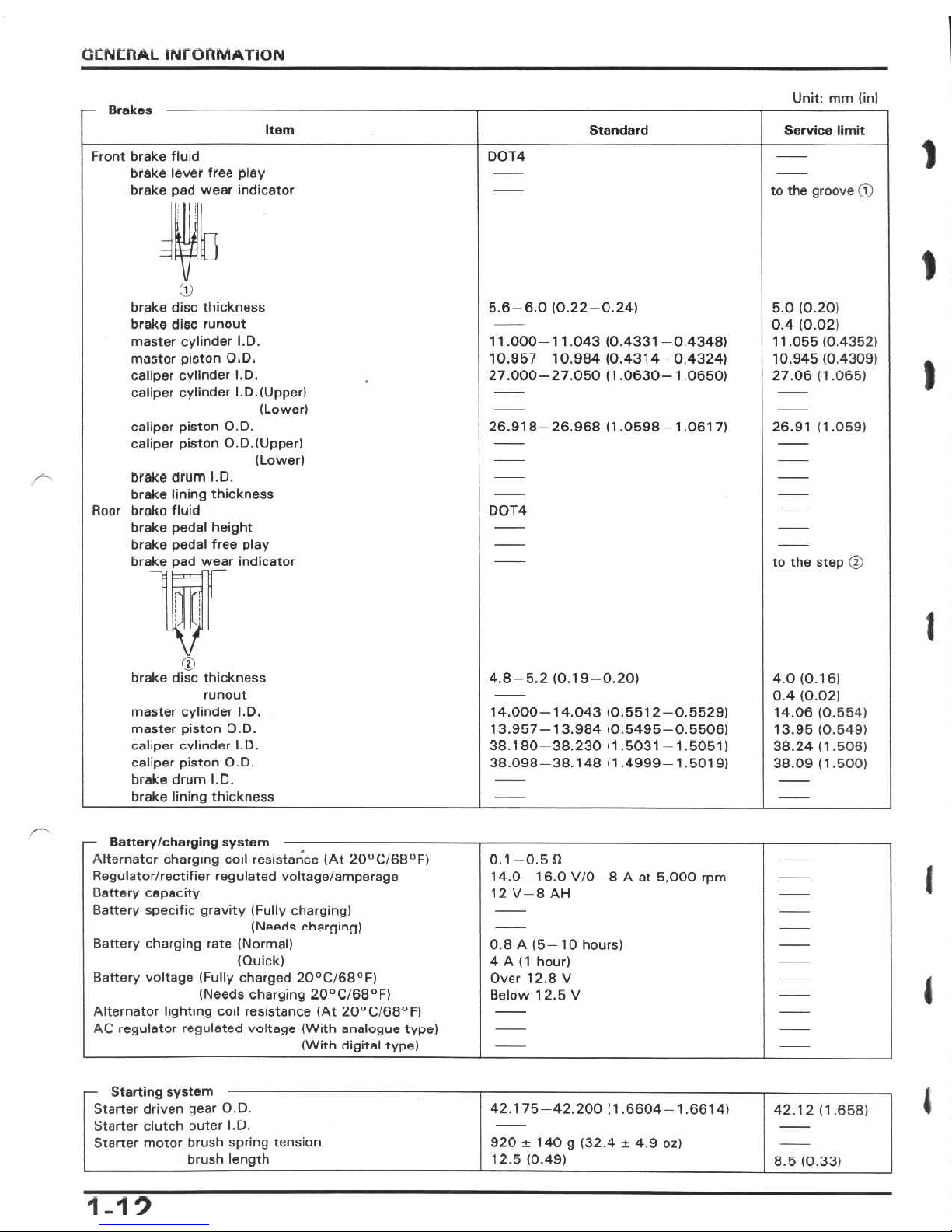
Brakes
Item
Standard
Service
limit
1
Front
brake
fluid
brake
lever
free
play
brake
pad
wear
indicator
D0T4
to
the
groove
©
D
1
©
brake
disc
thickness
brake
disc
runout
master
cylinder
I.D.
moetor
piston
O.D,
caliper
cylinder
I.D.
caliper
cylinder
I.D.
(Upper)
(Lower)
5.
6-6.0
(0.22-0.24)
5.0
(0.20)
0.4
(0.02)
11.055
(0.4352)
10.945
(0.4309)
27.06
(1.065)
11.000-11.043
(0.4331-0.4348)
10.957
10.984(0.4314
0.4324)
27.000-27.050
(1.0630-1.0650)
I
caliper
piston
O.D.
caliper
piston
O.D.
(Upper)
(Lower)
26.918-26.968
(1.0598-1.0617)
26.91
(1.059)
brake
drum
I.D.
brake
lining
thickness
Rear
brake
fluid
brake
pedal
height
brake
pedal
free
play
brake
pad
wear
indicator
lijr
v
D0T4
to
the
step
©
1
©
brake
disc
thickness
runout
master
cylinder
I.D.
master
piston
O.D.
caliper
cylinder
I.D.
caliper
piston
O.D.
brake
drum
I.D.
brake
lining
thickness
4.8-5.
2
(0.19-0.20)
4.0
(0.16)
0.4
(0.02)
14.06
(0.554)
13.95
(0.549)
38.24
(1.506)
38.09
(1.500)
14.000-14.043
(0.5512-0.5529)
13.957-13.984
(0.5495-0.5506)
38.180-38.230
(1
.5031
—
1
.5051
)
38.098-38.148
(1.4999-1.5019)
-
Battery/charging
system
-
Alternator
charging
coil
resistance
(At
20UC/68UF)
Regulator/rectifier
regulated
voltage/amperage
Battery
capacity
Battery
specific
gravity
(Fully
charging)
(Needs
charging)
0.1-0.
5
fi
14.0-16.0
V/0-8
A
at
5,000
rpm
12
V—8AH
I
Battery
charging
rate
(Normal)
(Quick)
0.8
A
(5-10
hours)
4
A
(1
hour)
Over
12.8
V
Below
12.5
V
Battery
voltage
(Fully
charged
20°C/68°F)
(Needs
charging
20°C/68°F)
Alternator
lighting
coil
resistance
(At
20UC/68°F)
AC
regulator
regulated
voltage
(With
analogue
type)
(With
digital
type)
1
-
Starting
system
-
Starter
driven
gear
O.D.
Starter
clutch
outer
I.D.
Starter
motor
brush
spring
tension
brush
length
1
42.175-42.200
(1.6604-1.6614)
42.12
(1.658)
920
±
140
g
(32.4
±
4.9
oz)
12.5
(0.49)
8.5
(0.33)
1-19
'1
-
G
-
-
-
-m
i>
—
-
-
I
IN
11
m
II
J
—
—
I<l
>
—
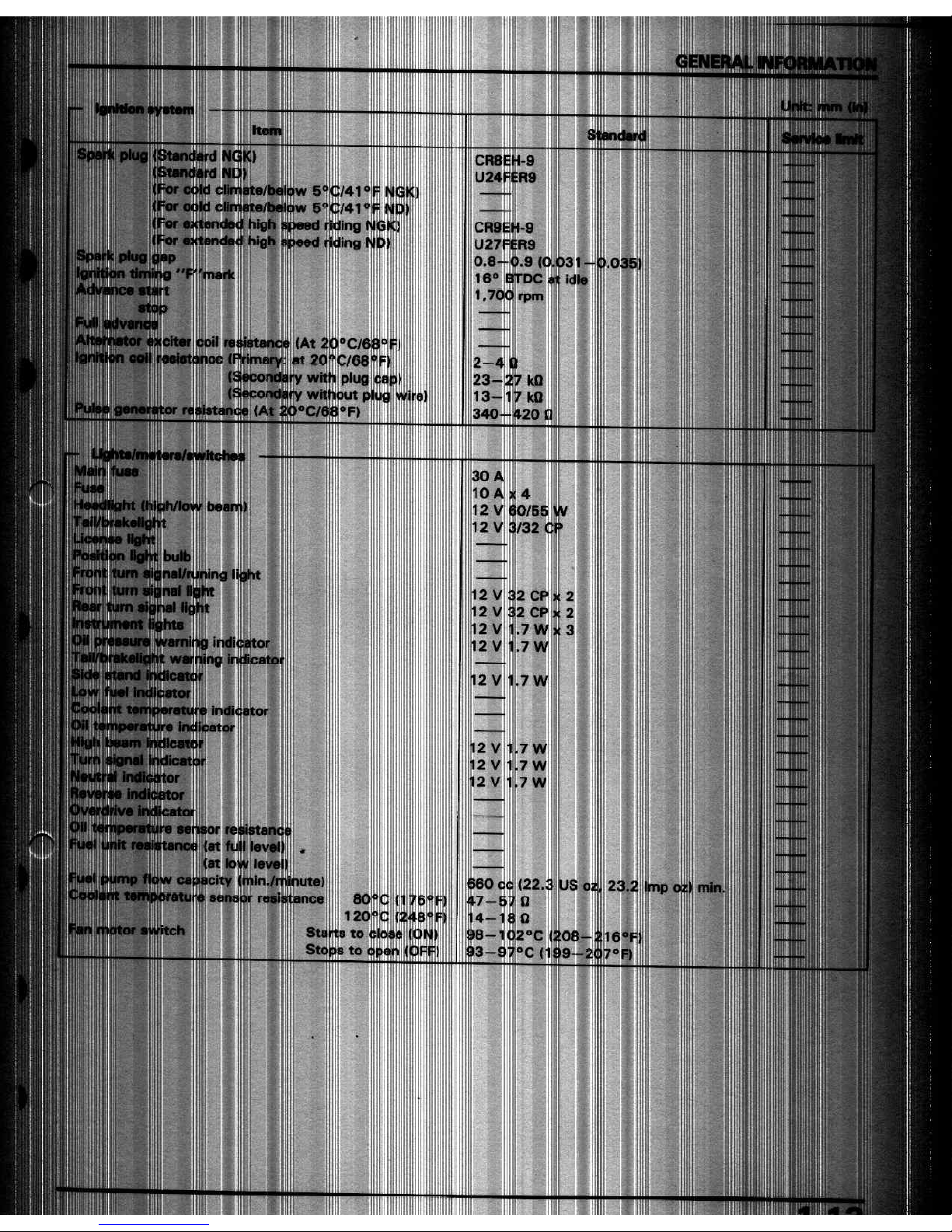
CR8EH-9
U24FER9
5°C/41
0
5ftC/41
°
iding
riding
m
I
i
hi
Cl
9
;
“1
U27
19
i.9
(0.031-
rDC
at
idle
0.8
1.035
"P
16°
€
1.
rpm
I
!
(At
20°C/6
at
?0"C/68
ilre
I
>
(I
2-4
I
plug
23-
kQ
without
C/68°F)
9
wire]
13-
kQ
!
re
it
340-420
Q
!
I
111
ililllll
-
ii
!
ii'ilri!
-
i
:
III®
II
30
A
1
illli!;]
10
A
4
IrHlJlll
“"HI
12
V
’
iMi
ih
iijij
"Hllll'Hjlll
l|!ill|'l|
!
i
1
'ill
ii
j
i'l<
''lilllili
Ii!
.11
ii
l!i
'
"||
ii
mi
i:ll'|.||llh
•
;
:ill:l|
»l
•
iill'lili
III
plitl
!lll|il|l||i!
-
1
!ll|i|i
IP
!
5
12
V
2
I
I'i:
"
111!
M
CP
12
V
2
'lil
li'i|
'
1
ill
1
i|n
III!
iViiifltfliliiJNM
12
V
2
12
V
.7
3
12
V
.7
12
V
as
mui
■7
W
12
V
MiMi
■7
W
7W
12
V
3
I
12
V
'
at
I
Ii
I
at
l<
lin./i
:e)
360
cc
‘23
(22.3
23.2
mp
IS
o;
min.
80°C
Starts
to
co«e
Sto
s
to
(
0
-1
3
■i:
°C
16°F
-9
°C
(
7°F)
1
-
t
;
V
■
i
•
8
S:
m
«1
-
-
ilill!
GENERAL
INFORMATION
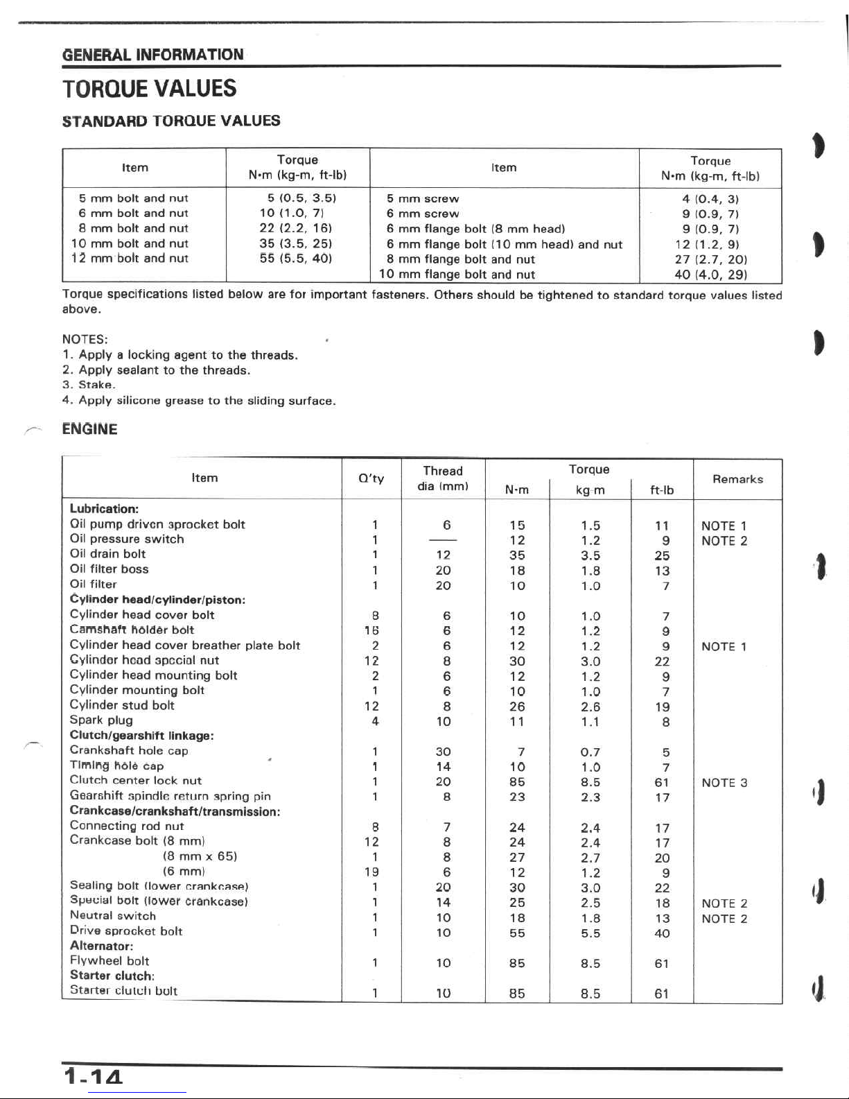
TORQUE
VALUES
STANDARD
TORQUE
VALUES
I
Torque
N-m
(kg-m,
ft-lb)
Torque
N*m
(kg-m,
ft-lb)
Item
Item
5
(0.5,
3.5)
10
(1.0,
7)
22
(2.2,
16)
35
(3.5,
25)
55
(5.5,
40)
5
mm
bolt
and
nut
6
mm
bolt
and
nut
8
mm
bolt
and
nut
1
0
mm
bolt
and
nut
1
2
mm
bolt
and
nut
5
mm
screw
6
mm
screw
6
mm
flange
bolt
(8
mm
head)
6
mm
flange
bolt
(10
mm
head)
and
nut
8
mm
flange
bolt
and
nut
10
mm
flange
bolt
and
nut
4
(0.4,
3)
9
(0.9,
7)
9
(0.9,
7)
12
(1.2,
9)
27
(2.7,
20)
40
(4.0,
29)
t
Torque
specifications
listed
below
are
for
important
fasteners.
Others
should
be
tightened
to
standard
torque
values
listed
above.
I
NOTES:
1
.
Apply
a
locking
agent
to
the
threads.
2.
Apply
sealant
to
the
threads.
3.
Stake.
4.
Apply
silicone
grease
to
the
sliding
surface.
ENGINE
Torque
kg
m
Thread
dia
(mm)
Item
Q'ty
Remarks
N-m
ft-lb
Lubrication:
Oil
pump
driven
sprocket
bolt
Oil
pressure
switch
Oil
drain
bolt
Oil
filter
boss
Oil
filter
Cylinder
head/cylinder/piston:
Cylinder
head
cover
bolt
Camshaft
holder
bolt
Cylinder
head
cover
breather
plate
bolt
Cylinder
head
special
nut
Cylinder
head
mounting
bolt
Cylinder
mounting
bolt
Cylinder
stud
bolt
Spark
plug
Clutch/gearshift
linkage:
Crankshaft
hole
cap
Timing
hole
cap
Clutch
center
lock
nut
Gearshift
spindle
return
spring
pin
Crankcase/crankshaft/transmission:
Connecting
rod
nut
Crankcase
bolt
(8
mm)
(8
mm
x
65)
(6
mm)
Sealing
bolt
(lower
crankcase)
Spueial
bolt
(lower
crankcase)
Neutral
switch
Drive
sprocket
bolt
Alternator:
Flywheel
bolt
Starter
clutch:
Starter
clutch
bolt
1
6
15
1.5
11
NOTE
1
NOTE
2
1
12
1.2
9
1
12
35
3.5
25
I
1
20
18
1.8
13
1
20
10
1.0
7
8
6
10
1.0
7
IB
6
12
1.2
9
2
6
12
1.2
9
NOTE
1
12
8
30
3.0
22
2
6
12
1.2
9
1
6
10
1.0
7
12
8
26
2.6
19
4
10
1 1
1.1
8
1
30
7
0.7
5
1
14
10
1.0
7
1
20
85
8.5
61
NOTE
3
1
1
8
23
2.3
17
8
7
24
2.4
17
12
8
24
2.4
17
1
8
27
2.7
20
19
6
12
1.2
9
<1
1
20
30
3.0
22
1
14
25
2.5
18
NOTE
2
NOTE
2
1
10
18
1.8
13
1
10
55
5.5
40
1
10
85
8.5
61
•J
1
10
85
8.5
61
1-1
a.
GENERAL
INFORMATION
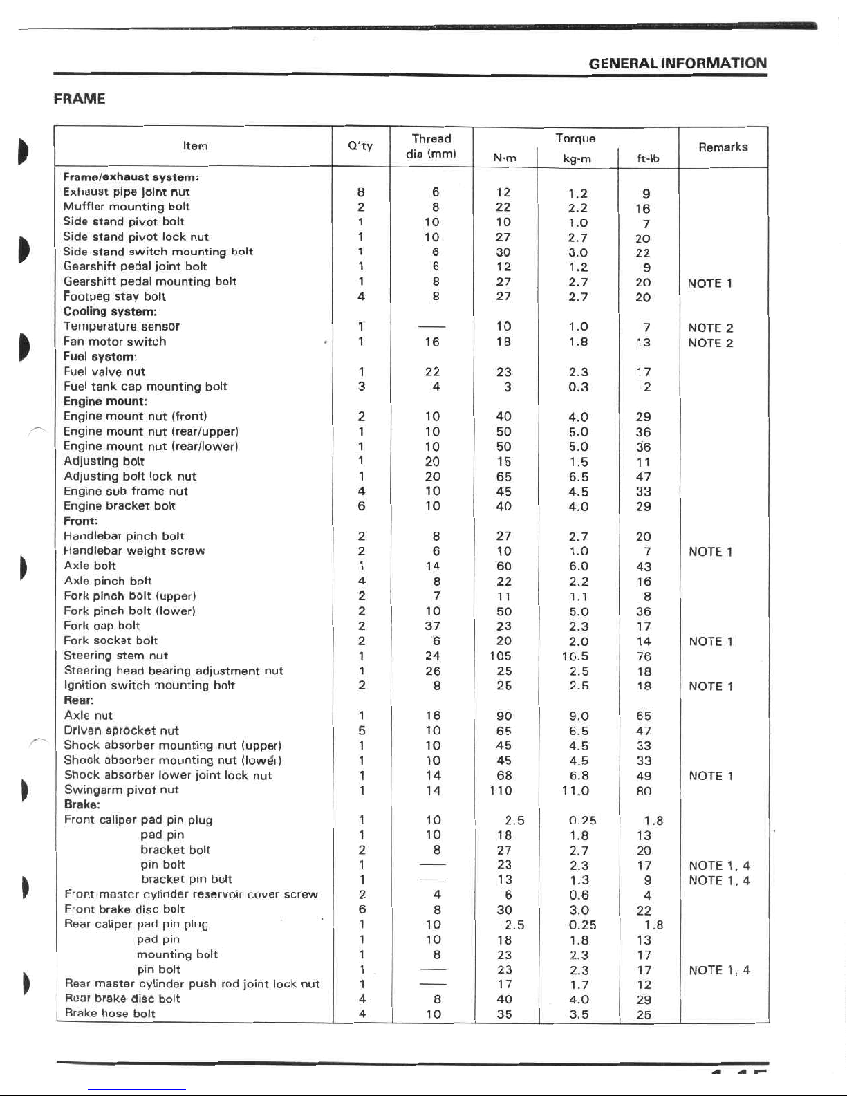
FRAME
Thread
dia
(mm)
Torque
kg-m
>
Item
Q'ty
Remarks
N-m
ft-lb
Frame/exhaust
system:
Exhaust
pipe
joint
nut
Muffler
mounting
bolt
Side
stand
pivot
bolt
Side
stand
pivot
lock
nut
Side
stand
switch
mounting
holt
Gearshift
pedal
joint
bolt
Gearshift
pedal
mounting
bolt
Footpeg
stay
bolt
Cooling
system:
Temperature
sensor
Fan
motor
switch
Fuel
system:
Fuel
valve
nut
Fuel
tank
cap
mounting
bolt
Engine
mount:
Engine
mount
nut
(front)
Engine
mount
nut
(rear/upper)
Engine
mount
nut
(rear/lower)
Adjusting
bolt
Adjusting
bolt
lock
nut
Engino
oub
fromc
nut
Engine
bracket
bolt
Front:
Handlebar
pinch
bolt
Handlebar
weight
screw
Axle
bolt
Axle
pinch
bolt
Fork
pinch
bolt
(upper)
Fork
pinch
bolt
(lower)
Fork
oop
bolt
Fork
socket
bolt
Steering
stem
nut
Steering
head
bearing
adjustment
nut
Ignition
switch
mounting
bolt
Rear:
Axle
nut
Driven
sprocket
nut
Shock
absorber
mounting
nut
(upper)
Shook
absorber
mounting
nut
(lowÿr)
Shock
absorber
lower
joint
lock
nut
Swingarm
pivot
nut
Brake:
Front
caliper
pad
pin
plug
pad
pin
bracket
bolt
pin
bolt
bracket
pin
bolt
Front
mo3tcr
cylinder
reservoir
cover
screw
Front
brake
disc
bolt
Rear
caliper
pad
pin
plug
pad
pin
mounting
bolt
pin
bolt
Rear
master
cylinder
push
rod
joint
lock
nut
Rear
brake
disc
bolt
Brake
hose
bolt
6
8
12
1.2
9
2
8
22
2.2
16
1
10
10
1.0
7
10
1
27
2.7
20
»
6
30
1
3.0
22
1
6
12
1.2
9
8
1
27
2.7
20
NOTE
1
4
8
27
2.7
20
10
1
1.0
7
NOTE
2
NOTE
2
I
18
1
16
1.8
13
22
1
23
2.3
17
3
3
4
0.3
2
2
10
40
4.0
29
10
50
1
5.0
36
36
1
10
50
5.0
20
1
15
1.5
11
20
1
65
6.5
47
10
45
4
4.5
33
6
40
10
4.0
29
2
8
27
2.7
20
6
2
10
1.0
NOTE
1
7
1
60
14
6.0
43
4
8
22
2.2
16
2
7
1
1
1.1
8
2
10
50
5.0
36
2
23
37
2.3
17
2
6
20
2.0
14
NOTE
1
1
24
105
10.5
76
1
26
25
2.5
18
2
8
25
2.5
18
NOTE
1
1
16
90
9.0
65
5
10
65
6.5
47
1
10
45
4.5
33
1
10
45
4.5
33
14
1
68
6.8
NOTE
1
49
)
1
14
110
1
1.0
80
1
10
2.5
0
25
1.8
1
10
18
1.8
13
2
8
27
2.7
20
1
23
2.3
17
NOTE
1,
4
NOTE
1,
4
1
13
1.3
9
»
2
4
6
0.6
4
6
8
30
3.0
22
1
10
2.5
0.25
1.8
1
10
18
1.8
13
1
8
23
2.3
17
1
23
2.3
NOTE
1,
4
17
\
1
17
1.7
12
4
8
40
4.0
29
4
10
35
3.5
25
GENERAL
INFORMATION
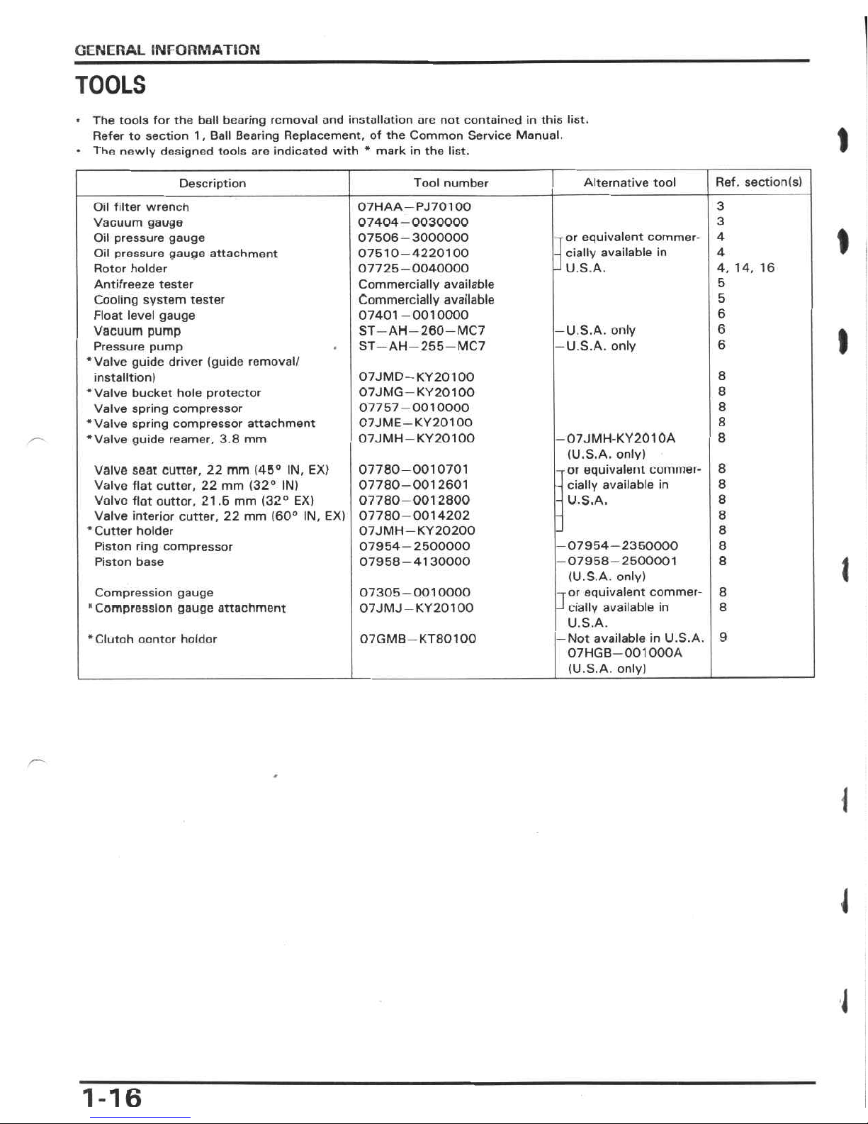
TOOLS
•
The
tools
for
the
boll
bearing
removal
and
installation
arc
not
contained
in
this
list.
Refer
to
section
1
,
Ball
Bearing
Replacement,
of
the
Common
Service
Manual.
•
The
newly
designed
tools
are
indicated
with
*
mark
in
the
list.
1
Ref.
section(s)
Alternative
tool
Tool
number
Description
3
07HAA—PJ701
00
07404-0030000
07506-3000000
07510-4220100
07725-0040000
Commercially
available
Commercially
available
07401-0010000
ST
—AH—
260
—
MC7
ST
—
AH
—
255
—
MC7
Oil
filter
wrench
Vacuum
gauge
Oil
pressure
gauge
Oil
pressure
gauge
attachment
Rotor
holder
Antifreeze
tester
Cooling
system
tester
Float
level
gauge
Vacuum
pump
Pressure
pump
‘Valve
guide
driver
(guide
removal/
installtion)
•Valve
bucket
hole
protector
Valve
spring
compressor
•Valve
spring
compressor
attachment
•Valve
guide
reamer,
3.8
mm
3
I
4
-ror
equivalent
commer-
-
daily
available
in
J
U.S.A.
4
4,
14,
16
5
5
6
6
—
U.S.A.
only
—
U.S.A.
only
I
6
8
07JMD
—
KY20100
07JMG
—
KY201
00
07757-0010000
07JME
—
KY201
00
07JMH
—
KY201
00
8
8
8
—
07JMH-KY201
OA
(U.S.A.
only)
-ror
equivalent
cummer-
-
dally
available
in
-
U.S.A.
8
8
07780-0010701
07780-0012601
07780-0012800
07780-0014202
07JMH
—
KY20200
07954-2500000
07958-4130000
valve
seat
cutter,
22
mm
(45°
IN,
EX)
Valve
flat
cutter,
22
mm
(32°
IN)
Volvo
flat
outtor,
21.6
mm
(32°
EX)
Valve
interior
cutter,
22
mm
(60°
IN,
EX)
•Cutter
holder
Piston
ring
compressor
Piston
base
8
8
8
8
-07954-2350000
-07958-2500001
(U.S.A.
only)
or
equivalent
commer¬
cially
available
in
U.S.A.
—
Not
available
in
U.S.A.
07HGB
—
001
000A
(U.S.A.
only)
8
8
1
8
07305-0010000
07JMJ
—
KY20100
Compression
gauge
"Compression
gauge
attachment
J
8
9
07GMB
—
KT801
00
•Clutoh
oontor
holdor
l
J
J
1-16
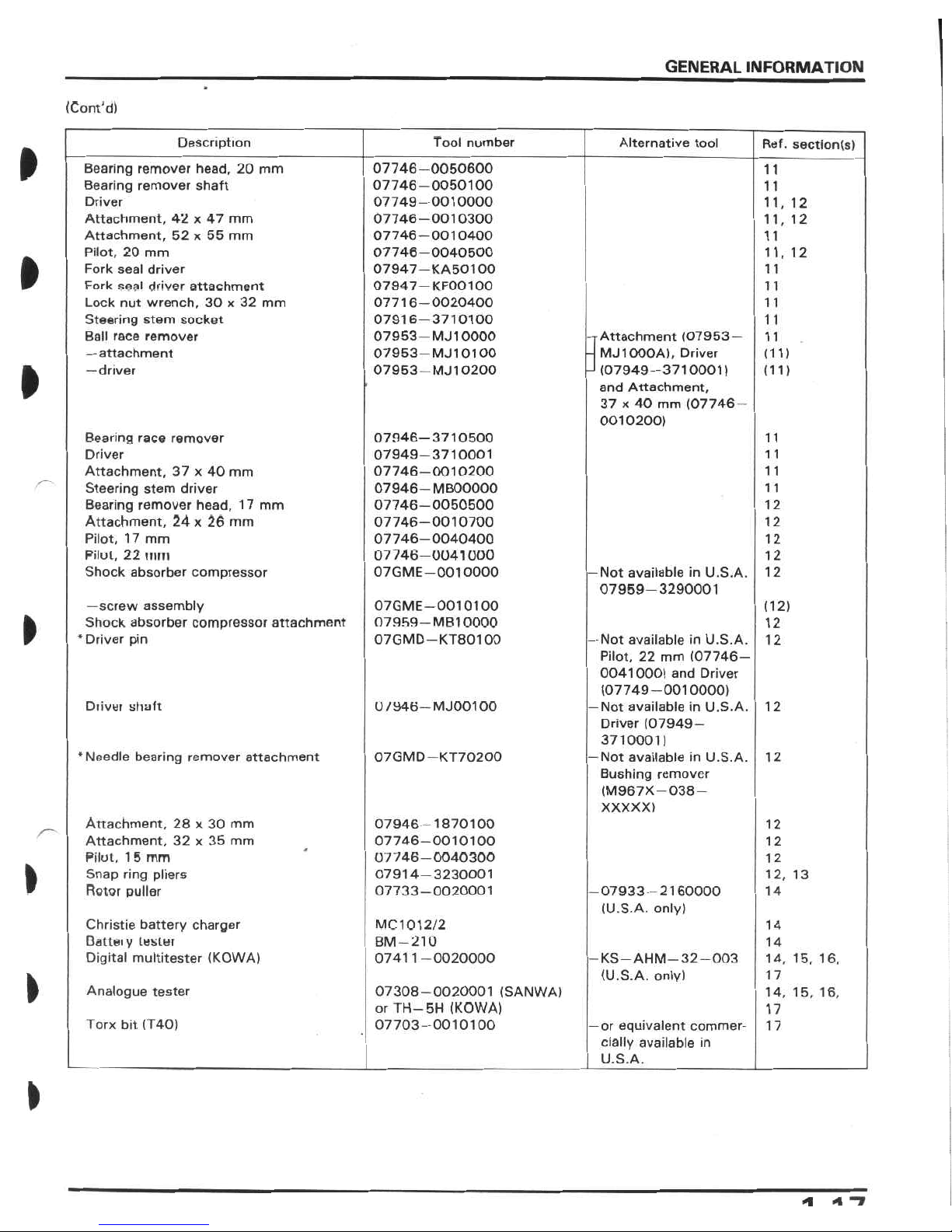
GENERAL
INFORMATION
(Corn'd)
Tool
number
Description
Alternative
tool
Ref.
section(s)
ft
07746-0050600
07746-0050100
07749-0010000
07746-0010300
07746-0010400
07746-0040500
07947-
KA501
00
07947
-KF001
00
07716-0020400
07916-3710100
07953-
MJ
10000
07953
—
MJ1
01
00
07953
—
MJ
10200
Bearing
remover
head,
20
mm
Bearing
remover
shaft
Driver
Attachment,
42
x
47
mm
Attachment,
52
x
55
mm
Pilot,
20
mm
Fork
seal
driver
Fork
seal
driver
attachment
Lock
nut
wrench,
30
x
32
mm
Steering
stem
socket
Ball
race
remover
—
attachment
—driver
1
1
11
11,
12
11,
12
11
11,
12
ft
11
11
11
11
-ÿAttachment
(07953
—
-
MJ1000A),
Driver
-l
(07949-3710001)
and
Attachment,
37
x
40
mm
(07746
—
0010200)
1
1
(11)
ft
(11)
Bearing
race
remover
Driver
Attachment,
37
x
40
mm
Steering
stem
driver
Bearing
remover
head,
17
mm
Attachment,
24
x
26
mm
Pilot,
1
7
mm
Pilot,
22
mm
Shock
absorber
compressor
07946-3710500
07949-3710001
07746-0010200
07946-
MB00000
07746-0050500
07746-0010700
07746-0040400
07746-0041000
07GME
—
001
0000
1 1
11
11
1
1
12
12
12
12
—
Not
available
in
U.S.A.
07959-3290001
12
—screw
assembly
Shock
absorber
compressor
attachment
‘Driver
pin
07GME
—
0010100
07959
—
MB1
0000
07GMD
—
KT801
00
(12)
ft
12
—
Not
available
in
U.S.A.
Pilot,
22
mm
(07746
—
0041000)
and
Driver
(07749-0010000)
—
Not
available
in
U.S.A.
Driver
(07949-
3710001)
—
Not
available
in
U.S.A.
Bushing
remover
(M967X—
038
—
XXXXX)
12
U
/946—
MJ001
00
Diivur
shaft
12
‘Needle
bearing
remover
attachment
07GMD
—
KT70200
12
Attachment,
28
x
30
mm
Attachment,
32x35
mm
Pilot,
1
5
mm
Snap
ring
pliers
Rotor
puller
07946-1870100
07746-0010100
07746-0040300
07914-3230001
07733-0020001
12
12
12
ft
12,
13
-07933-2160000
(U.S.A.
only)
14
Christie
battery
charger
Qatteiy
tester
Digital
multitester
(K0WA)
MC1012/2
BM-210
07411-0020000
14
14
—
KS
—
AHM
—
32
—
003
(U.S.A.
only)
14, 15,
16,
17
ft
Analogue
tester
07308-0020001
(SANWA)
or
TH-5H
(K0WA)
07703-0010100
14,
15,
16,
17
Torx
bit
(T40)
—
or
equivalent
commer¬
cially
available
in
U.S.A.
17
ft
<1
4
1
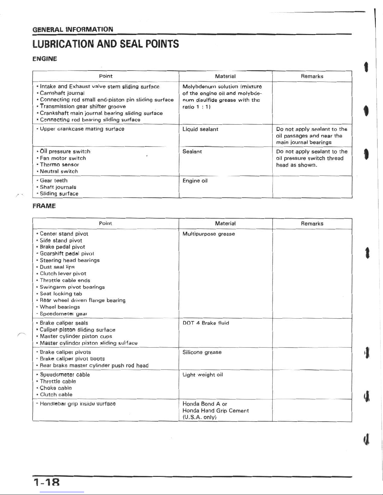
GENERAL
INFORMATION
LUBRICATION
AND
SEAL
POINTS
ENGINE
I
Point
Material
Remarks
•
Intake
and
Exhaust
valve
stem
sliding
surface
•
Camshaft
journal
•
Connecting
rod
small
end-piston
pin
sliding
surface
•
Transmission
gear
shifter
groove
•
Crankshaft
main
journal
bearing
sliding
surface
•
Connecting
rod
bearing
sliding
surface
Molybdenum
solution
(mixture
of
the
engine
oil
and
molybde¬
num
disulfide
grease
with
the
ratio
1:1)
t
•
Upper
crankcase
mating
surface
Liquid
sealant
Do
not
apply
sealant
to
the
oil
passages
and
near
the
main
journal
bearings
•
Oil
pressure
switch
•
Fan
motor
switch
•
Thermo
sensor
•
Neutral
switch
Sealant
Do
not
apply
sealant
to
the
oil
pressure
switch
thread
headasshown.
•
Gear
teeth
•
Shaft
journals
-
Sliding
surface
Engine
oil
/
'
FRAME
Material
Point
Remarks
•
Center
stand
pivot
•
Side
stand
pivot
*
Brake
pedal
pivot
■
Gearshift
pedal
pivot
•
Steering
head
bearings
•
Dust
seal
lips
•
Clutch
lever
pivot
•
Throttle
cable
ends
•
Swingarm
pivot
bearings
•
Seat
locking
tab
*
Rear
wheel
driven
flange
bearing
•
Wheel
bearings
-
Speedometer
geai
Multipurpose
grease
I
Brake
caliper
seals
Caliper-piston
sliding
surface
Master
cylinder
piston
cups
Master
cylinder
pi3ton
sliding
surface
DOT
4
Brake
fluid
J
Brake
caliper
pivots
Brake
caliper
pivot
boots
Rear
brake
master
cylinder
push
rod
head
Silicone
grease
Speedometer
cable
Throttle
cable
Choke
cable
Clutch
cable
Light
weight
oil
4
Honda
Bond
A
or
Honda
Hand
Grip
Cement
(U.S.A.
only)
-
Handlebar
grip
inside
surface
4
1-18
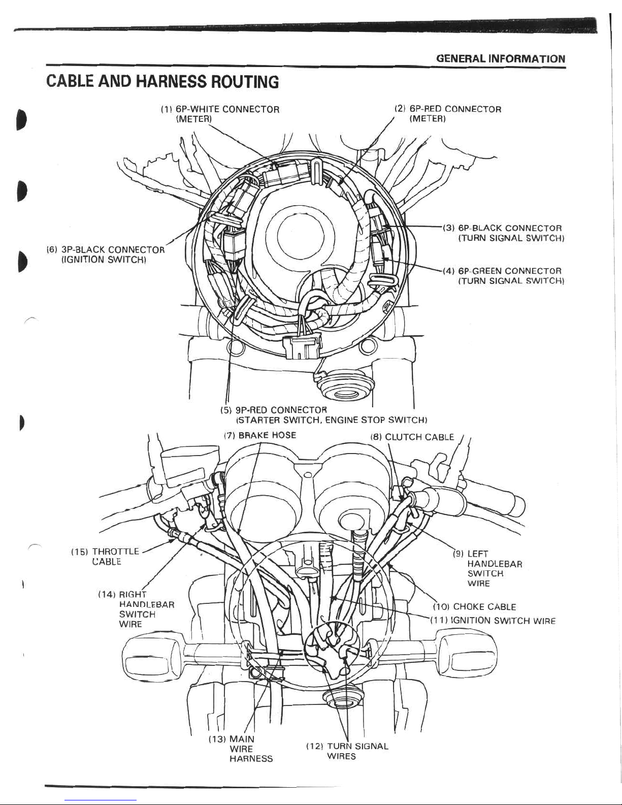
GENERAL
INFORMATION
CABLE
AND
HARNESS
ROUTING
(2)
6P-RED
CONNECTOR
-
(METER)
(1)
6P-WHITE
CONNECTOR
(METER)
ft
ft
(3)
6P
BLACK
CONNECTOR
(TURN
SIGNAL
SWITCH)
(6)
3P-BLACK
CONNECTOR
(IGNITION
SWITCH)
ft
(4)
6P-GREEN
CONNECTOR
(TURN
SIGNAL
SWITCH)
4
'ÿ
(5)
9P-RED
CONNECTOR
(STARTER
SWITCH,
ENGINE
STOP
SWITCH)
(7)
BRAKE
HOSE
I
(8)
CLUTCH
CABLE
O
fa1
(15)
THROTTLE
CABLE
(9)
LEFT
HANDLEBAR
SWITCH
WIRE
£
(14)
RIGHT
HANDLEBAR
SWITCH
WIRE
(10)
CHOKE
CABLE
(11)
IGNITION
SWITCH
WIRE
t
I
i
cz
T
mm
V.
V
l
rd
A
(13)
MAIN
WIRE
HARNESS
(12)
TURN
SIGNAL
WIRES
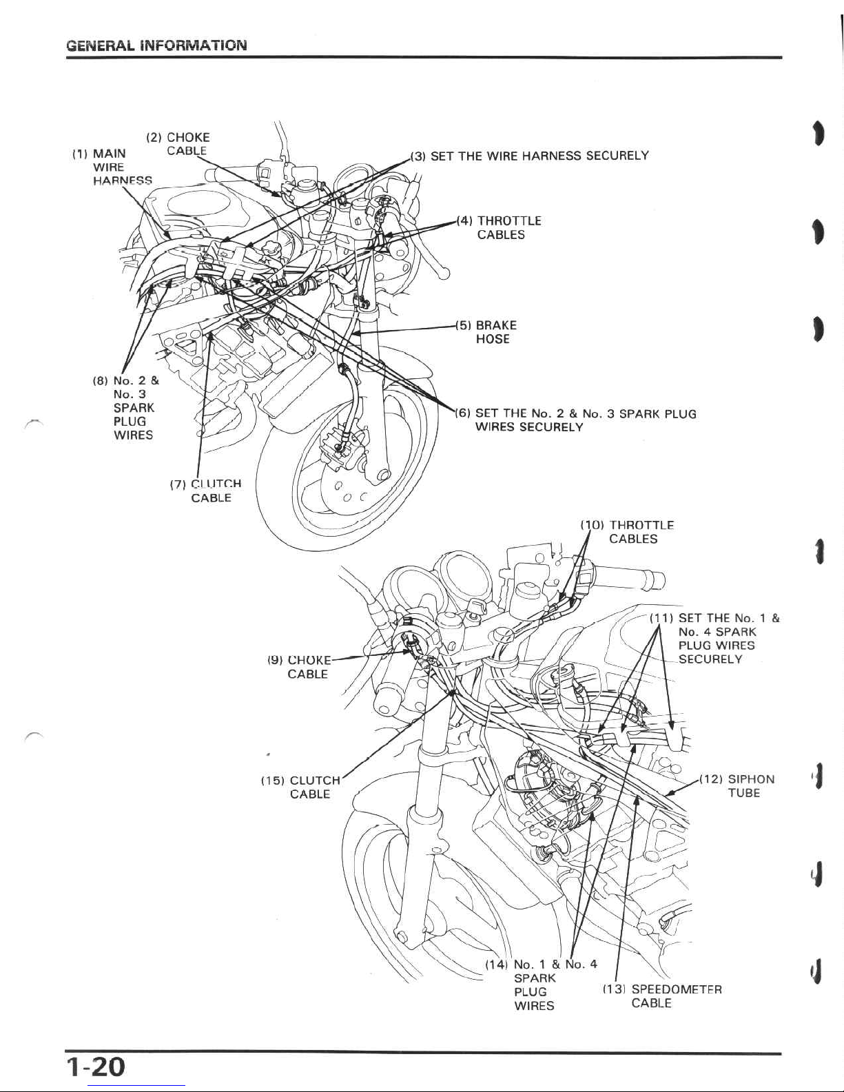
GENERAL
INFORMATION
1
(2)
CHOKE
CADLE
(1)
MAIN
WIRE
HARNFSS
.(3)
SET
THE
WIRE
HARNESS
SECURELY
)
(4)
THROTTLE
CABLES
-I®
I
3
o)
&
)
5)
BRAKE
HOSE
oO
(8)
No.
2
&
No.
3
SPARK
PLUG
WIRES
16)
SET
THE
No.
2
&
No.
3
SPARK
PLUG
WIRES
SECURELY
(7)
Cl
l
ITCH
CABLE
O
o
c
(10)
THROTTLE
/
CABLES
t
TD
(11)
SET
THE
No.
1
&
J
No.
4
SPARK
PLUG
WIRES
-
SECURELY
(9)
CHOKE
CABLE
a
Q
5s
J.
s
\
I
•0
2)
SIPHON
TUBE
(15)
CLUTCH
CABLE
v.
iV
as
ry
$
Wi-
O,
y
J
l
X
Is*
'
f
r
\
\\
r
No.
1
&
No.
4
SPARK
PLUG
WIRES
(13)
SPEEDOMETFR
CABLE
1-20
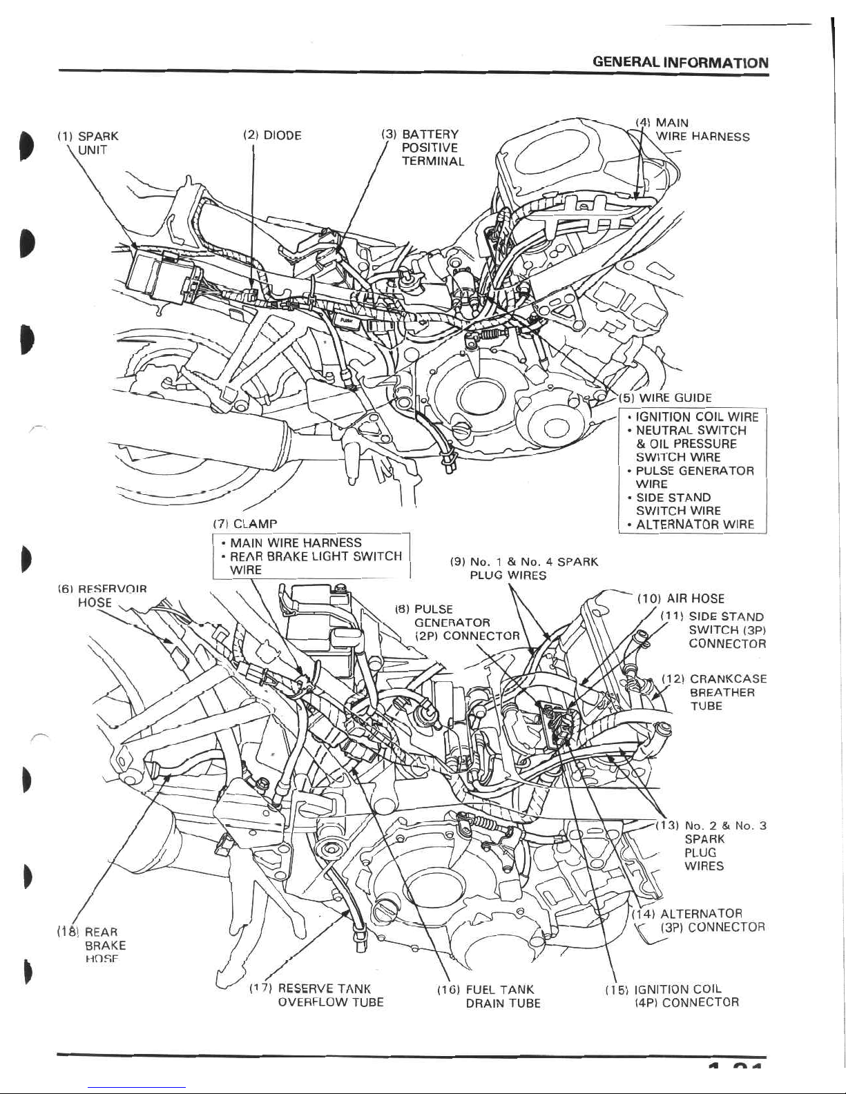
GENERAL
INFORMATION
j4)
MAIN
rjVWIRE
HARNESS
(3)
BATTERY
/
POSITIVE
'
TERMINAL
(2)
DIODE
I
(1)
SPARK
\UNIT
1
I
O
P>
Qz
A
<2
I
si
0
Q.
(5)
WIRE
GUIDE
•
IGNITION
COIL
WIRE
•
NEUTRAL
SWITCH
&
OIL
PRESSURE
SWITCH
WIRE
•
PULSE
GENERATOR
WIRE
•
SIDE
STAND
SWITCH
WIRE
•
ALTERNATOR
WIRE
O
/“ÿ
(7)
CLAMP
•
MAIN
WIRE
HARNESS
•
REAR
BRAKE
LIGHT
SWITCH
WIRE
(9)
No.
1
&
No.
4
SPARK
PLUG
WIRES
(6)
RESFRVDIR
HOSE
v
,
(10)
AIR
HOSE
/(11)
SIDE
STAND
'LS
SWITCH
(3P)
36
CONNECTOR
(8)
PULSE
\
GENERATOR
'
N
(2P)
CONNECTOR
v\'
(12)
CRANKCASE
(
BREATHER
\
TUBE
7
a
%
/
V
/
to
>
y
o
"(13)
No.
2
&
No.
3
SPARK
PLUG
WIRES
vQ
<@x
/
O
>
(14)
ALTERNATOR
V
(3P)
CONNECTOR
(18)
REAR
BRAKE
HDSF
o
/
(17)
RESERVE
TANK
OVERFLOW
TUBE
(15)
IGNITION
COIL
(4P)
CONNECTOR
(16)
FUEL
TANK
DRAIN
TUBE
«•
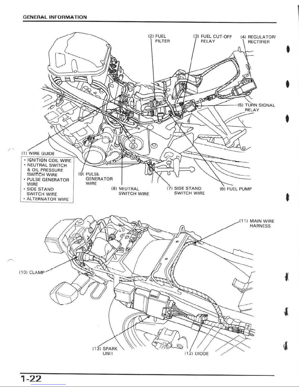
GENERAL
INFORMATION
(3)
FUEL
CUT-OFF
/
RELAY
FUEL
FILTER
(4)
REGULATOR/
\
RECTIFIER
P_5
♦
s
Q
7
&
(5)
TURN
SIGNAL
RELAY
I
o
,<2>
©
50
(1)
WIRE
GUIDE
&
•
IGNITION
COIL
WIRE
•
NEUTRAL
SWITCH
&
OIL
PRESSURE
SWITCH
WIRE
•
PULSE
GENERATOR
WIRE
•
SIDE
STAND
SWITCH
WIRE
•
ALTERNATOR
WIRE
(9)
PULSE
GENERATOR
WIRE
(8)
NEUTRAL
SWITCH
WIRE
(7)
SIDE
STAND
SWITCH
WIRE
(6)
FUEL
PUMP
t
(11)
MAIN
WIRE
HARNESS
S')
ftP*
■’-i
?&.
'A
0
1
1
I
0
(10)
CLAMP
I
l
i
O.
n
(13)
SPARK
UNI
I
(12)
DIODE
/
1-22
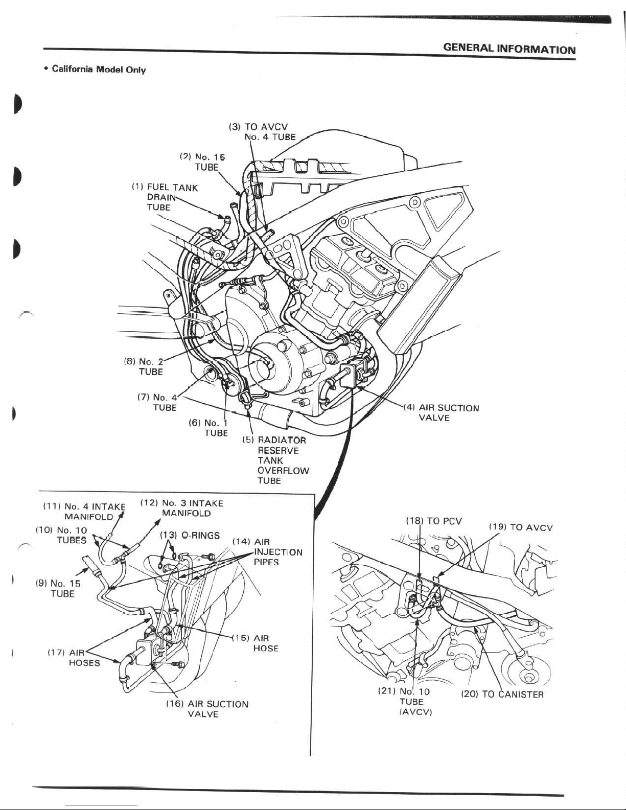
GENERAL
INFORMATION
•
California
Model
Only
(3)
TO
AVCV
No.
4
TUBE
(?)
No.
15
TUBE
\\\
(1)
FUEL
TANK
DRAIN\
TUBE
tc
>
»56
oj
h/j
(8)
No.
2
TUBE
(7)
No.
4'
TUBE
(4)
AIR
SUCTION
VALVE
I
(6)
No.
1
TUBE
(b)
RADIATOR
RESERVE
TANK
OVERFLOW
TUBE
(12)
No.
3
INTAKE
MANIFOLD
(11)
No.
4
INTAKE
MANIFOLDÿ
(18)
TO
PCV
(19)
TO
AVCV
(10)
No.
10
TUBES
(13)
0-RINGS
(14)
AIR
■INJECTION
PIPES
O.
(9)
No.
15
TUBE
rQ
n
<s
I
1
'o
915)
AIR
HOSE
I
(17)
AIR
HOSES
(21)
No!
10
TUBE
(AVCV)
(20)
TO
CANISTER
(16)
AIR
SUCTION
VALVE
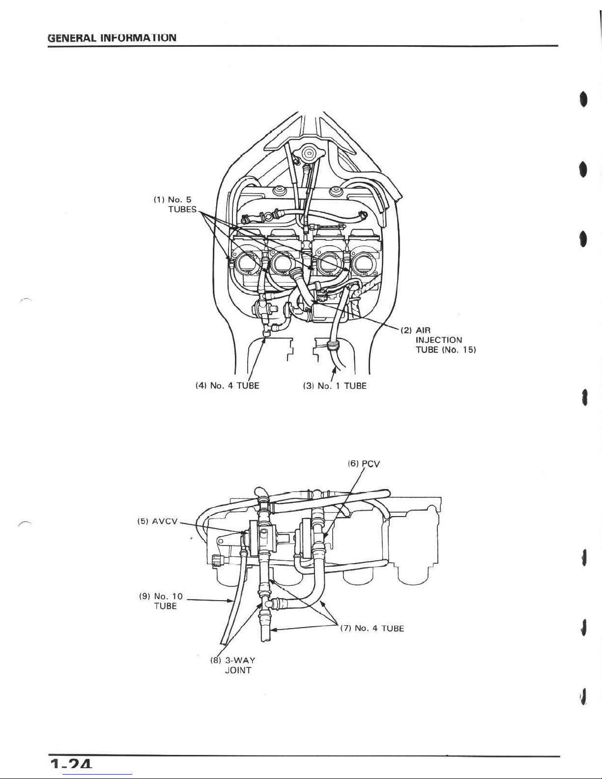
GENERAL
INhORMATION
I
m
i
09
m
(1)
No.
5
TUBES
I
(2)
AIR
INJECTION
TUBE
(NO.
15)
r
(4)
No.
4
TUBE
(3)
No.1TUBE
I
(6)
PCV
(5)
AVCV
n
P
J
Ml
(9)
No.
10
TUBE
(7)
No.
4
TUBE
(8)
3-WAY
JOINT
I
1.9/1
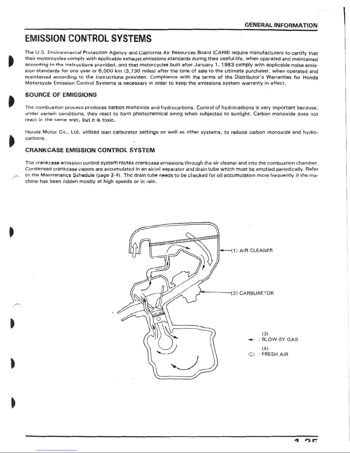
GENERAL
INFORMATION
EMISSION
CONTROL
SYSTEMS
The
U.S.
environmental
Protection
Agency
and
California
Air
Resources
Board
(CARB)
require
manufacturers
to
certify
that
their
motorcycles
comply
with
applicable
exhaust
emissions
standards
during
their
useful
life,
when
operated
and
maintained
according
to
the
instructions
provided,
and
that
motorcycles
built
after
January
1,1
983
comply
with
applicable
noise
emis¬
sion
standards
for
one
year
or
6,000
km
(3,730
miles)
after
the
time
of
saletothe
ultimate
purchaser,
when
operated
and
maintained
according
to
the
instructions
provided.
Compliance
with
the
terms
of
the
Distributor's
Warranties
for
Honda
Motorcycle
Emission
Control
Systems
is
necessary
in
order
to
keep
the
emissions
system
warranty
in
effect.
I
SOURCE
OF
EMISSIONS
I
The
combustion
process
produces
carbon
monoxide
and
hydrocarbons.
Control
of
hydrocarbons
is
very
important
because,
under
certain
conditions,
they
react
to
form
photochemical
smog
when
subjected
to
sunlight.
Carbon
monoxide
does
not
react
in
the
same
way,
but
it
is
toxic.
Honda
Motor
Co.,
Ltd.
utilized
lean
carburetor
settings
as
well
as
other
systems,
to
reduce
carbon
monoxide
and
hydro¬
carbons.
I
CRANKCASE
EMISSION
CONTROL
SYSTEM
The
crankcase
emission
control
system
routes
Crankcase
emissions
through
the
air
cleaner
and
into
the
combustion
chamber.
Condensed
crankcase
vapors
are
accumulated
in
an
air/oil
separator
and
drain
tube
which
must
be
emptied
periodically.
Refer
to
the
Maintenance
Schedule
(page
3-4).
The
drain
tube
needs
to
be
checked
for
oil
accumulation
more
frequently
if
the
ma¬
chine
has
been
ridden
mostly
at
high
speeds
or
in
rain.
>
1)
AIR
CLEANER
>)
i2)
CARBURETOR
O
I
Pc
(3)
:
BLOW-BY
GAS
(4)
Cl
:
FRESH
AIR
>
*i
orr
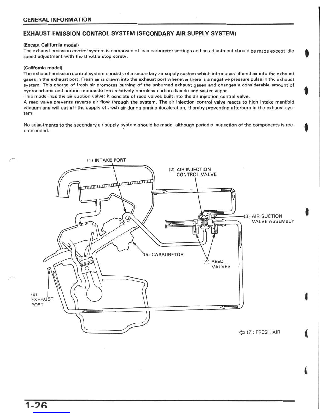
GENERAL
INFORMATION
EXHAUST
EMISSION
CONTROL
SYSTEM
(SECONDARY
AIR
SUPPLY
SYSTEM)
(Except
California
model)
The
exhaust
emission
control
system
is
composed
of
lean
carburetor
settings
and
no
adjustment
should
be
made
except
idle
speed
adjustment
with
the
throttle
stop
screw.
I
(California
model)
The
exhaust
emission
control
system
consists
of
a
secondary
air
supply
system
which
introduces
filtered
air
into
the
exhaust
gases
in
the
exhaust
port.
Fresh
airisdrawn
into
the
exhaust
port
whenever
there
is
a
negative
pressure
pulse
in
the
exhaust
system.
This
charge
of
fresh
air
promotes
burning
of
the
unburned
exhaust
gases
and
changes
a
considerable
amount
of
hydrocarbons
and
carbon
monoxide
into
relatively
harmless
carbon
dioxide
and
water
vapor.
This
model
has
the
air
suction
valve;
it
consists
of
reed
valves
built
into
the
air
injection
control
valve.
A
reed
valve
prevents
reverse
air
flow
through
the
system.
The
air
injection
control
valve
reacts
to
high
intake
manifold
vacuum
and
will
cut
off
the
supply
of
fresh
air
during
engine
deceleration,
thereby
preventing
afterburn
in
the
exhaust
sys¬
tem.
No
adjustments
to
the
secondary
air
supply
system
should
be
made,
although
periodic
inspection
of
the
components
is
rec¬
ommended.
I
(1)
INTAKE
PORT
(2)
AIR
INJECTION
CONTROL
VALVE
HI
I
■(3)
AIR
SUCTION
VALVE
ASSEMBLY
V
‘(5)
CARBURETOR
(4)
REED
VALVES
O
(6)
I
EXHAUST
PORT
<>
4
O
(7):
FRESH
AIR
4
1
-2fi
 Loading...