

Page 1

540 Ш. FtiwerTake Off No.LM-16001-72
Assembly Instructions and Parts List’
Assembly
1. Install the lift shaft on the rear of the tractor with the
two set collars inside the brackets as shown. Secure
with the two setscrews provided (Figure 1).
Mfr'sNal72
V
_____________^____________
[>a(o)[iiiQ[ML.Dir[l’
forT-I0,M2,T-15&T-16TrattOR
4. Install the belt stops as shown. Adjust the upper belt
stop for 1/8 inch clearance between the belt and the stop.
Adjust the lower one for 1/16 inch to 1/8 inch clearance
between the belt and the stop. The capscrew provided
for the upper belt stop replaces the original capscrew on
die tractor.
_
2. Mount the upper arms of the frame assembly on the lift
shaft, then align the holes in the lower arms with the
holes in the tractor frame and secure with two pins and
two quick pins (Figure 1).
3. Mount the drive pulley on the tractor PTO shaft using a
key and secure with the setscrew provided (Figure 2).
Lubrication
The 540 R. P. M. PTO unit has three standard size grease
fittings. One fitting on each bearing housing and one on the
frame assembly. They should be lubricated occasionally
with general automotive type grease. Be sure to wipe each
fitting clean before greasing to prevent grit and dirt from
being carried into bearings with the new grease.
Part No, 24755
Page 2
9
Page 3

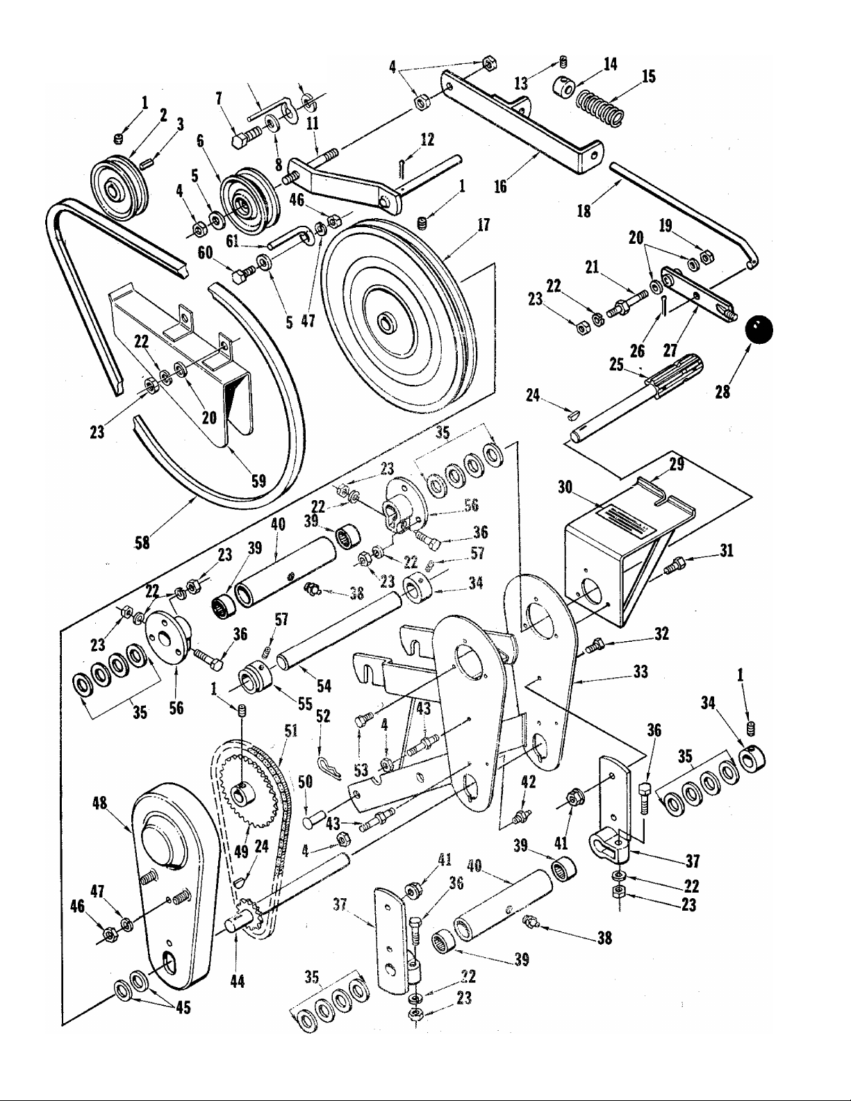
540 R.P.M. P.T.O.
/ '"'i
No. Description
i
1
SCREW-set, 5/16-18 x 5/16
2
PULLEY
3
KEY
NUT-hex lock. 3/8-16
4
5 WASHER-flat, 3/8 LM-09173-78 2
6 PULLEY-idler
7
SCREW-cap, 7/16-14 X 1-1/4
8 WASHER-flat, 7/16
9 STOP-belt
10 WASHER-loek, 7/16
11 PIVOT ASSEMBLY
PIN-cotter, 1/8 X 1
12
SCREW-set, 1/4-20 x 3/8
13
COLLAR-set LM-81910-22
14
15
SPRING
16 GUIDE.ASSEMBLY-clutch
17 PULLEY
ROD-clutch LM-01670-25
18
NUT-hex lock, 5/16-18
19
20 WASHER-flat, 5/16
21
STUD
WASHER-lock, 5/16
22
23 NUT-hex. 5/16-18
KEY-woodruff
24
25
SHAFT ASSEMBLY
2,6 PIN-cotter, 3/32 x 5/8
27
HANDLE ASSEMBLY
BA L£-knob
28
\ /
GUARD ASSEMBLY - PTO
29
DE CA L-war ning
30
31 SCREW-cap, 5/16-18 x 3/4
SCREW-cap, 3/8-16 x 3/4
32
33 FRAME ASSEMBLY
Part No..
LM-09286-91
LM-01642-02
LM-80610-81 1
LM-09234-28 5
LM-01052-85
LM-09234-71
LM-09184-30
LM-16060-14
LM-09181-99 1
LM-01670-21
LM-09184-52
LM-09038-07
LM-01631-03
LM-80815-03
LM-01670-20
LM-09233-62
LM-09176-42
LM-01620-63
LM-09173-56 12
LM-09173-72
LM-09051-23 2
LM-01670-14
LM-09220-00
LM-01670-26
LM-80210-50
LM-01670-11
LM-01670-30
LM-09173-97 3
LM-09081-27
LM-16074-59
Qty.
12
No. Description Part No. Qty,
4
34 COLLAR-set
1
1
1
1
1
1
1
1
1
1
1
1
1
1
4
1
1
1
1
1
1
1
2
1
WASHER LM-80610-12
35
36 SCREW-cap, 5/16-18 X 1-1/2
37
SUPPORT ASSEMBLY-clamp
38
FITTING-grease
39 BEARING-needle
40
, HOUSING-bearing
41
NUT-flange, hex lock, 3/8-16
42 FITTING-grease
STUD LM-01067-71
43
44 SHAFT ASSEMBLY
WASHER
45
46
NUT-hex, 3/8-16
47 WASHER-lock, 3/8
GUARD ASSEMBLY-chain LM-01725-50
48
SPROCKET LM-01670-17
49
50
PIN
51 CHAIN w/conn. link
52
QUICK PIN
53 SCREW-cap, 5/16-18 x 5/8
SHAFT-lift
54
55 COLLAR-set
56 FLANGE ASSEMBLY
SCREW-set
57
BELT-”V" LM-01230-73
58
54
GUARD ASSEMBLY-belt
60
SCREW-cap, 3/8-16 x 1
STOP-belt LM-01670-32
61
Accessory
PAINT-blue, 14 oz. spray can
LM-80210-10
LM-09199-33
LM-01064-79
LM-09128-08
LM-01542-58
LM-01670-06
LM-09283-52
LM-07270-12
LM-01670-07
LM-01670-19
LM-09169-50
LM-09169-6 5
LM-01550-37
LM-01060-58
LM-01067-88
LM-09193-18
LM-01542-16
LM-01576-95
LM-01670-09
LM-09117-12
LM-01730-13
LM-09077-31
LM-16076-89
2
16
4
2
2
4
2
4
1
2
1
2
3
3
1
1
2
1
2
2
1
1
2
2
1
1
1
1
ALWAYS FURNISH MODEL AND SERIAL NUMBER WHEN ORDERING PARTS.
Page 4

V..
....
y
PRINTED IN U.S.A.
HOMELirr
(
«textronl
PORT CHESTER, NEW YORK, U.S.A. 10573
DIVISION
E1726EZ
 Loading...