

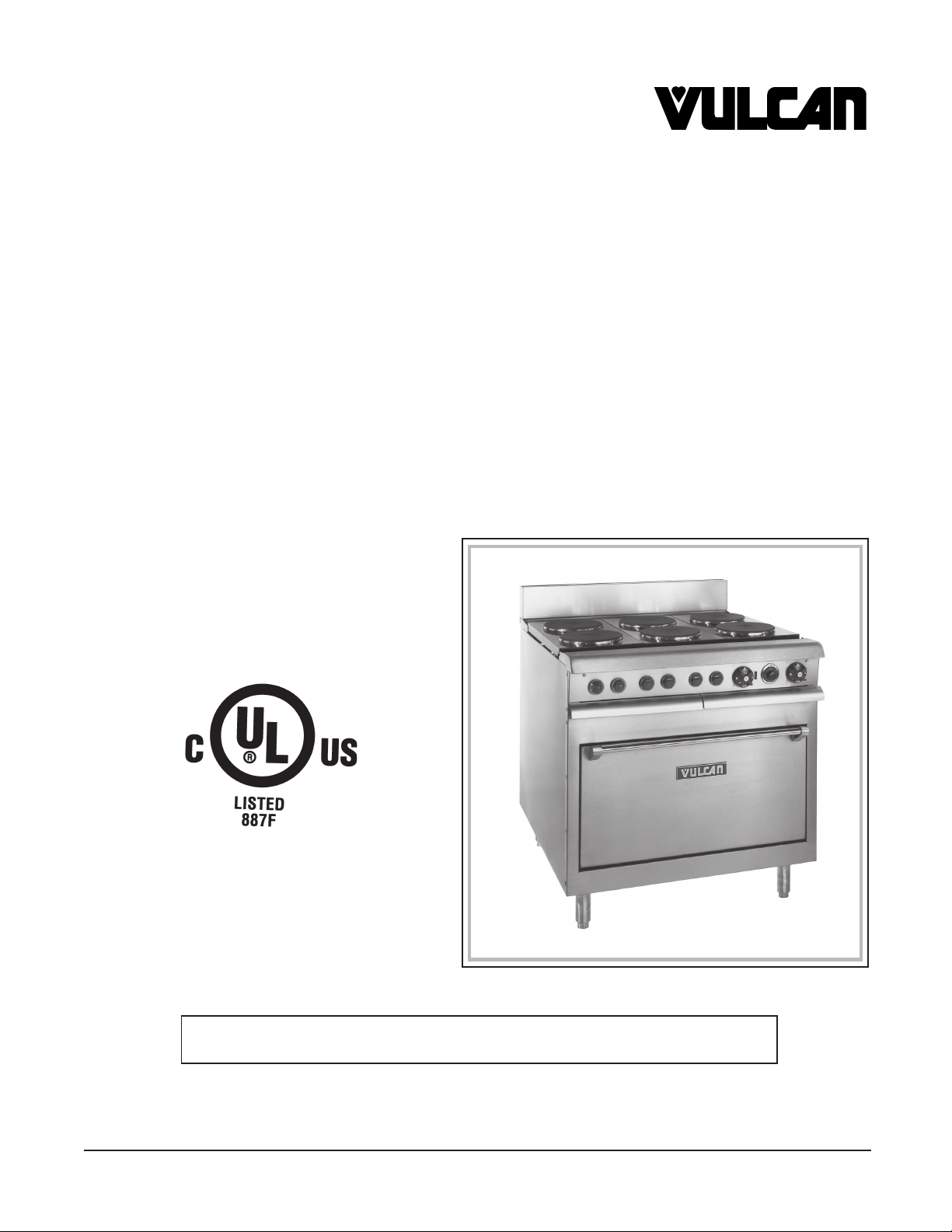
Hobart VR6 Installation Manual
INSTALLATION &
OPERATION MANUAL
ELECTRIC HEAVY DUTY RANGES
MODELS VR, VS, VM, VEX, VMX AND VRC
VR4 Range
For additional information on Vulcan-Hart or to locate an authorized parts
and service provider in your area, visit our website at www.vulcanhart.com
VULCAN-HART
DIVISION OF ITW FOOD EQUIPMENT GROUP, LLC
F33210 (Rev. A 1-04) www.vulcanhart.com
P.O. BOX 696, LOUISVILLE, KY 40201-0696
TEL. (502) 778-2791

The following models have been discontinued and are no longer available:
VR1(C) VS1 VM1 through VM7 VEX1
VR3(C) VS3 VMX1
VR6(C) VS6 VMX2
VR7(C) VS7 VMX3
2

INSTALLATION AND OPERATION MANUAL
FOR ELECTRIC RANGES
MODELS VR, VS, VM, VEX, VMX AND VRC INDEX
SAVE THESE INSTRUCTIONS FOR FUTURE REFERENCE
Vulcan ranges are produced with quality workmanship
and material. Proper installation, usage and
maintenance of your range will result in many years of
satisfactory performance.
The manufacturer suggests that you thoroughly read
this entire manual and carefully follow all of the
instructions provided.
DESCRIPTION PAGE
INDEX 3
VULCAN RANGE CONFIGURATIONS 4
GENERAL 6
INSTALLATION 7
UNPACKING 7
LOCATION 7
BUMPER BAR INSTALLATION 8
LEVELING 8
ELECTRICAL CONNECTIONS 8
OPERATION 11
CONTROLS 11
BEFORE FIRST USE 12
USING THE RANGE TOP 12
USING THE VR SERIES OVEN 13
USING THE VRC SERIES OVEN 13
OPERATING HINTS 14
COOKING TIPS 14
CLEANING 15
CLEANING BLOWER WHEEL 15
3
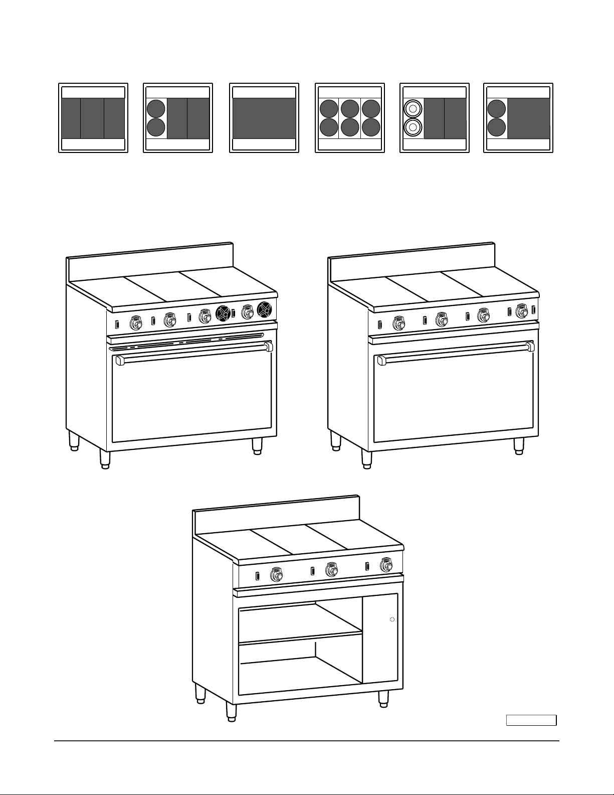
VULCAN RANGE CONFIGURATIONS
VR1, VR2
VM1, VM2
VS1, VS2
VR3, VR6
VM3, VM6
VS3, VS6
VR5
VM5
VS5
VR4
VM4
VS4
VR3, VR6
VM3, VM6
VS3, VS6
VR7
VM7
VS7
VR1C, VR2C VR3C, VR6C VR5C VR4C VR3C, VR6C VR7C
(SHOWN WITH OPTIONAL
HIGH SPEED ELEMENTS)
VR SERIES
VS SERIES
4
VRC SERIES
PL - 51130-1
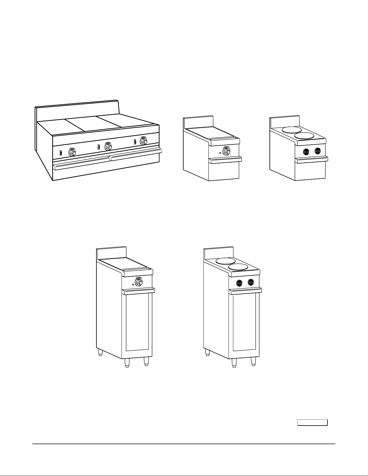
VM1
VM2
VULCAN RANGE CONFIGURATIONS
VMX1
VMX2
VMX3
VEX1
VEX2
VEX3
PL - 51130-2
5

GENERAL
The various Vulcan electric VR, VS, VM, VEX and VMX Family Series standard ranges and VRC Series
convection ranges are equipped as follows:
MODEL DESCRIPTION
RANGES WITH STANDARD OVEN
VR1 (3) 12" x 24" (305 x 610) hot tops.
VR2 (3) 12" x 24" (305 x 610) all purpose plates, (2) with grease troughs on right and left sides
and (1) without grease trough in the center.
VR3 (2) 91/2" (241) dia. round French hot plates at left and (2) 12" x 24" (305 x 610) hot tops at center
and right.
VR4 (6) 91/2" (241) dia. round French hot plates.
VR5 36" (914) wide griddle with front grease trough.
VR6 (2) 91/2" (241) dia. round French hot plates at left and (2) 12" x 24" (305 x 610) all purpose plates
at center and right.
VR7 (2) 91/2" (241) dia. round French hot plates at left and 24" (610) griddle top at right.
MODULAR RANGES WITHOUT OVEN
VM1 (3) 12" x 24" (305 x 610) hot tops.
VM2 (3) 12" x 24" (305 x 610) all purpose plates, (2) with grease troughs on right and left sides and
(1) without grease trough in the center.
VM3 (2) 91/2" (241) dia. round French hot plates at left and (2) 12" x 24" (305 x 610) hot tops at center
and right.
VM4 (6) 91/2" (241) dia. round French hot plates.
VM5 36" (914) wide griddle with front grease trough.
VM6 (2) 91/2" (241) dia. round French hot plates at left and (2) 12" x 24" (305 x 610) all purpose plates
at center and right.
VM7 (2) 91/2" (241) dia. round French hot plates at left and 24" (610) griddle top at right.
12" (305) WIDE FULL BODY EXPANDO RANGES
VEX1 (1) 12" x 24" (305 x 610) hot top.
VEX2 (1) 12" x 24" (305 x 610) all purpose plate with side grease troughs.
VEX3 (2) 91/2" (241) dia. round French hot plates.
12"WIDE MODULAR EXPANDO RANGE
VMX1 (1) 12" x 24" (305 x 610) hot top.
VMX2 (1) 12" x 24" (305 x 610) all purpose plate with side grease troughs.
VMX3 (2) 91/2" (241) dia. round French hot plates.
RANGES WITH CONVECTION OVEN
VR1C (3) 12" x 24" (305 x 610) hot tops.
VR2C (3) 12" x 24" (305 x 610) all purpose plates, (2) with grease troughs on right and left sides and
(1) without grease trough in the center.
VR3C (2) 91/2" (241) dia. round French hot plates at left and (2) 12" x 24" (305 x 610) hot tops at center
and right.
VR4C (6) 91/2" (241) dia. round French hot plates.
VR5C 36" (914) wide griddle with front grease trough.
VR6C (2) 91/2" (241) dia. round French hot plates at left and (2) 12" x 24" (305 x 610) all purpose plates
at center and right.
VR7C (2) 91/2" (241) dia. round French hot plates at left and 24" (610) griddle top at right.
6

MODEL DESCRIPTION
RANGES WITH CABINET BODY
VS1 (3) 12" x 24" (305 x 610) hot tops.
VS2 (3) 12" x 24" (305 x 610) all purpose plates, (2) with grease troughs on right and left sides
and (1) without grease trough in the center.
1
VS3 (2) 9
/2" (241) dia. round French hot plates at left and (2) 12" x 24" (305 x 610) hot tops at
center and right.
VS4 (6) 91/2" (241) dia. round French hot plates.
VS5 36" (914) wide griddle with front grease trough.
VS6 (2) 91/2" (241) dia. round French hot plates at left and (2) 12" x 24" (305 x 610) all purpose
plates at center and right.
VS7 (2) 9
1
/2" (241) dia. round French hot plates at left and 24" (610) griddle top at right.
Hot tops and all purpose plates are not recommended for use as griddles.
Optional high speed elements are available in place of round French hot plates for use with 208/240 volts only.
The high speed elements are not recommended for stock pot work.
All VR and VRC ranges with oven sections are mounted on 6" (152) adjustable legs. Optionally, they may be
equipped with no legs (for masonry base mounting) or a 4" (102) toe base in place of legs.
All VR ranges with ovens are equipped with one oven rack. All VRC ranges with ovens are equipped with 3 oven
racks. Additional racks may be purchased as an option.
All VR and VRC ranges with full size ovens, VS cabinet base or VM modular ranges will have two drawers in the
front of the range under the cooking top area. The left-hand drawer is a baffled grease drawer, the right-hand
drawer is a warming drawer.
INSTALLATION
UNPACKING
Immediately after unpacking the range, check it for possible shipping damage. If the range is found to be
damaged after unpacking, save the packing material and contact the carrier within 7 days of delivery.
Prior to installation, verify that the electrical service agrees with the specifications on the data plate which is
located on the breaker cover door to the right of the oven cavity.
LOCATION
Position the range in its final installation position. Refer to the data plate for required clearances adjacent to
combustible and non-combustible construction. When a broiler is installed over the range, refer to the broiler
and range data plates for clearance requirements. Install the range so that the conduit can be placed into the
bottom entrance.
The VRC Convection Range will require a minimum 4" (102) clearance between a rear wall and motor cover. The
convection oven also comes equipped with 9" (229) wide, side bumper bars that must be attached to the range
if it is installed next to a combustible wall. Refer to BUMPER BAR INSTALLATION in this manual.
7
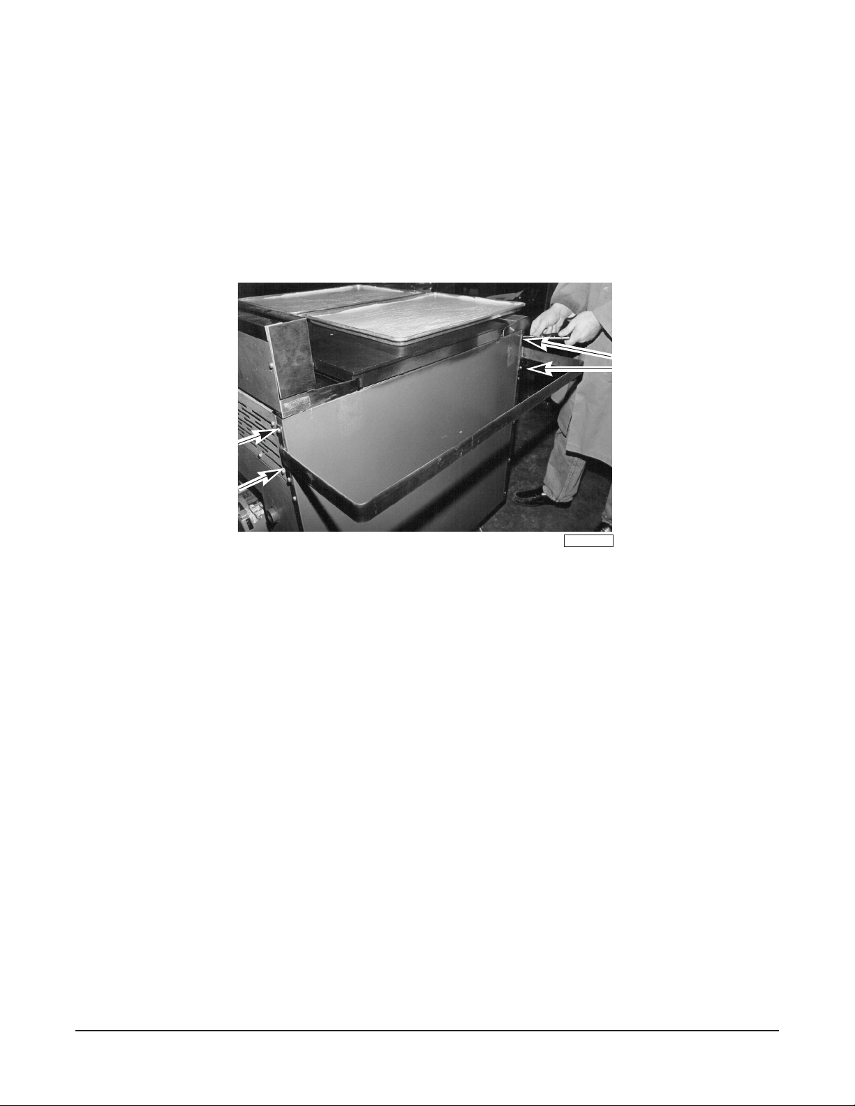
BUMPER BAR INSTALLATION (RANGES ON CASTERS ONLY)
There are 2 sets of bumper bars packaged separately and placed inside the oven compartment for shipping.
Bumper bars must be installed on the side(s) of the convection oven that is placed near a combustible wall during
operation.
1. Remove bumper bars from the oven cavity and unwrap.
2. Using a
wall.
5
¦16" (8) socket and socket driver, attach bumper bar to the side(s) of the oven nearest the combustible
Note that there are predrilled bumper bar mounting holes supplied on the sides and back of the oven
(Fig. 1).
Bumper Bar
Mounting
LEVELING
Full Body Ranges
Bumper Bar
Mounting
Location
Location
PL-40033-1
Fig. 1
Using a carpenter's level placed on top of the range, adjust the feet so the range is level from front to back and
from side to side.
Masonry Base/Toe Base
Using a carpenter's level, ensure that the base where the range will be installed is level. If the base is not level,
it must be levelled before installing the range.
ELECTRICAL CONNECTIONS
WARNING: ELECTRICAL AND GROUNDING CONNECTIONS MUST COMPLY WITH THE APPLICABLE
PORTIONS OF THE NATIONAL ELECTRICAL CODE AND/OR OTHER LOCAL ELECTRICAL CODES.
WARNING: DISCONNECT ELECTRICAL POWER SUPPLY AND PLACE A TAG AT THE DISCONNECT
SWITCH TO INDICATE THAT YOU ARE WORKING ON THE CIRCUIT.
Bring conduit containing the proper supply wire (size and type in accordance with latest edition of the National
Electrical Code ANSI/NFPA-70) to the range through the 2" (51) hole located in the bottom of the range. On
modular ranges and expando units, the conduit enters the range through the clearance hole located in the back
of the range. Use wire suitable for 75°C on ranges carrying more than 80 amps.
Connect the supply leads to the terminal block and the green grounding lead to the labeled ground lug.
8
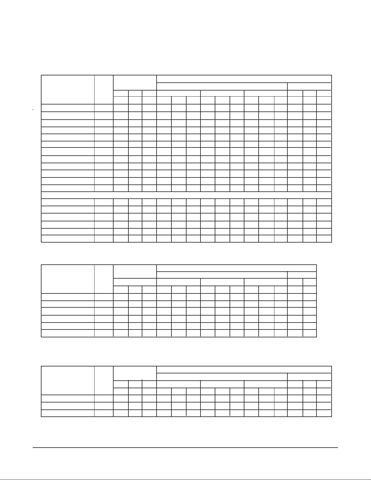
ELECTRICAL DATA CHARTS
VR RANGES WITH STANDARD OVENS OR VS RANGES WITH CABINET BODY
"N/A" RANGES NOT AVAILABLE 480 VOLT
3 PHASE LOAD NOMINAL AMPS PER LINE WIRE
TOTAL KW PER PHASE 3 PHASE 1 PHASE
KW 208V 240V 480V 208V 240V 480V 208V 240V 480V
MODEL CONN. X-Y Y-Z X-Z X Y Z X Y Z X Y Z XYZ XYZ XYZ
VR1,2,5 21.7 7.7 5 9 70 53 58 60 46 51 30 23 25 104 90 45
VR1,2,5 / VB73 27.7 10.7 8 — 82 78 71 71 68 61 — — — 133 115 —
VS,VM1,2,5 15 5 5 5 42 42 42 36 36 36 18 18 18 72 63 31
VS,VM1,2,5 / VB73 21 8 8 —546754475847— — —10188—
VR3,6,7 20.7 7.7 5 8 65 53 54 57 46 47 28 23 24 99 86 43
VR3,6,7 / VB73 26.7 10.7 8 — 78 78 67 68 68 58 — — — 128 111 —
VS,VM3,6,7 14 5 5 4 38 42 38 33 36 33 16 18 16 67 58 29
VS,VM3,6,7 / VB73 20 8 8 —506750435843— — —9683—
VR4 18.7 6.7 4 8 61 45 50 53 39 43 19 27 22 90 78 39
VR4 / VB73 24.7 9.7 7 8 74 70 63 64 60 54 27 30 33 119 103 N/A
VS,VM4 12 4 4 4 33 33 33 29 29 29 14 14 14 58 50 25
VS,VM4 / VB73 18 7 7 —465846405140 — — —8775—
480 Volt Only:
VR1,2,5 / VB73 21.7 7.7 11 9 ——————303436——N/A
VR3,6,7 / VB73 26.7 7.7 11 8 ——————283434——N/A
VS,VM1,2,5 / VB73 21 5 11 5 ——————182929——44
VS,VM3,6,7 / VB73 20 5 11 4 ——————162927——42
VR4 / VB73 24.7 6.7 10 8 ——————273033——N/A
VS,VM4 / VB73 18 4 10 4 ——————142525——38
VR RANGES WITH CONVECTION OVENS
3 PHASE LOAD NOMINAL AMPS PER LINE WIRE
TOTAL KW PER PHASE 3 PHASE 1 PHASE
208V,240V & 480V
KW
MODEL CONN. X-Y Y-Z X-Z X Y Z X Y Z X Y Z XYZ XYZ
VR1C,2C,5C 22 6.2 6.2 9.6 66 51 66 57 45 57 29 22 29 106 92
VR1C,2C,5C/VB73 28 9.2 9.2 9.6 78 76 78 68 66 68 34 33 34 135 117
VR3C,6C,7C 21 6.2 6.2 8.6 62 51 62 54 45 54 27 22 27 101 87
VR3C,6C,7C/VB73 27 9.2 9.2 8.6 74 76 74 64 66 64 32 33 32 130 112
VR4C 19 5.2 5.2 8.6 58 43 58 50 37 50 25 19 25 91 79
VR4C/VB73 25 8.2 8.2 8.6 70 68 70 61 59 61 30 29 30 120 104
208V 240V 480V 208V 240V
VEX AND VMX RANGES
3 PHASE LOAD NOMINAL AMPS PER LINE WIRE
TOTAL KW PER PHASE 3 PHASE 1 PHASE
KW 208V 240V 480V 208V 240V 480V 208V 240V 480V
MODEL CONN. X-Y Y-Z X-Z X Y Z X Y Z X Y Z XYZ XYZ XYZ
VEX,VMX1 5 2.5 2.5 — 11 21 11 9 18 9 4.5 9.0 4.5 24 21 10.4
VEX2,VMX2 5 ————————————242110.4
VEX3,VMX3 4 2 2 — 8 17 8 7 14 7 3.6 7.2 3.6 19 17 8.3
"VB73" in above charts denotes an electric elevated broiler installed over the range.
9
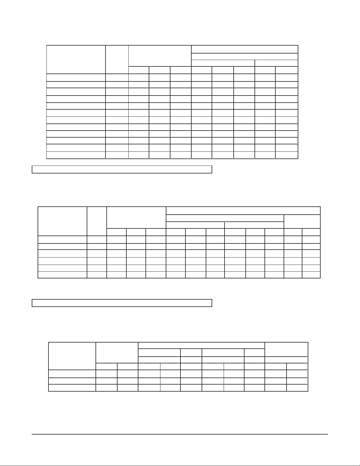
220/380, 240/415 VOLT VS/VM RANGES AND VR RANGES WITH OVEN
3 PHASE LOAD NOMINAL AMPS PER LINE WIRE
TOTAL KW PER PHASE 240/415 VOLT
KW 3 PHASE 1 PHASE
MODEL CONN. X-N Y-N Z-N X Y Z X Z
VR1,2,5 21.7 7.7 5 9 32 21 38 32 58
VR1,2,5 / VB73 27.7 10.7 8 9 45 33 38 45 71
VS,VM1,2,5 15 5 5 5 21 21 21 21 42
VS,VM1,2,5 / VB73 21 8 8 5 33 33 21 33 54
VR3,6,7 20.7 6.7 5 9 28 31 38 28 59
VR3,6,7 / VB73 26.7 9.7 8 9 41 33 38 41 71
VS,VM3,6,7 14 4 5 5 17 21 21 17 42
VS,VM3,6,7 / VB73 20 7 8 5 29 33 21 29 54
VR4 18.7 6.7 4 8 28 17 33 28 50
VR4 / VB73 24.7 9.7 7 8 41 29 33 41 62
VS,VM4 12 4 4 4 17 17 17 17 34
VS,VM4 / VB73 18 7 7 4 29 29 17 29 46
VOLTAGE FROM ANY PHASE TO NEUTRAL NOT TO EXCEED 250 VOLTS
220/380, 240/415 VOLT VRC RANGES WITH CONVECTION OVEN
3 PHASE LOAD NOMINAL AMPS PER LINE WIRE
TOTAL KW PER PHASE 3 PHASE 1 PHASE
KW 220/380V 240/415V
MODEL CONN. X-N Y-N Z-N X Y Z X Y Z X Z
VR1C,2C,5C 22 6.2 6.2 9.6 33 25 33 34 26 34 34 60
VR1C,2C,5C/VB73 28 9.2 9.2 9.6 40 38 40 41 39 41 41 80
VR3C,6C,7C 21 6.2 6.2 8.6 31 23 33 32 24 34 32 58
VR3C,6C,7C/VB73 27 9.2 9.2 8.6 37 35 38 38 37 39 38 76
VR4C 19 5.2 5.2 8.6 31 21 33 32 22 34 32 56
VR4C/VB73 25 8.2 8.2 8.6 37 33 38 38 34 39 38 73
VOLTAGE FROM ANY PHASE TO NEUTRAL NOT TO EXCEED 250 VOLTS
220/380, 240/415 VOLT VEX AND VMX RANGES WITHOUT OVEN
NOMINAL AMPS PER LINE WIRE LOAD
TOTAL KW 1PH,3-WIRE 2-WIRE 1PH,3-WIRE 2-WIRE KW/PHASE
CONN. 220/380 220 240/415 240 1 PHASE
MODEL 220/380 240/415 L1 L2 L1 L1 L2 L1 L1-N L2-N
VEX,VMX1 4.2 5 9.6 9.6 19.3 10.5 24 21 2.5 2.5
VEX2,VMX2 4.2 5 19.3 — 19.3 21 — 21 — —
VEX3,VMX3 3.4 4 7.8 7.8 15.6 8.5 19 17 2.0 2.0
"VB73" in above charts denotes an electric elevated broiler installed over the range.
10
 Loading...