

Page 1
OM-185 480B
March 1999
Processes
MIG (GMAW) Welding
Description
Weld Control For Spoolmatic Gun
HWC-115A
Page 2

From Hobart to You
Thank you and congratulations on choosing Hobart.
Now you can get the job done and get it done right.
We know you don’t have time to do it any other way.
This Owner’s Manual is designed to help you get the
most out of your Hobart products. Please take time
to read the Safety precautions. They will help you
protect yourself against
potential hazards on the
worksite. We’ve made
installation and operation
quick and easy. With Hobart you can count on
years of reliable service with proper
maintenance. And if for some reason the unit
Hobart is registered to the
ISO 9001 Quality System
Standard.
needs repair, there’s a Troubleshooting section
that will help you figure out what the problem
is. The parts list will then help you to decide
which exact part you may need to fix the
problem. Warranty and service information for
your particular model are also provided.
Hobart Welders manufactures a full line
of welders and welding related equipment.
For information on other quality Hobart
products, contact your local Hobart distributor
to receive the latest full line catalog or
individual catalog sheets. To locate your nearest
distributor or service agency call 1-877-Hobart1.
Hobart offers a Technical
Manual which provides
more detailed service and
parts information for your
unit. T o obtain a Technical
Manual, contact your local
distributor. Your distributor
can also supply you with
Welding Process Manuals
such as SMAW, GTAW,
GMAW, and GMA W-P.
Page 3
SECTION 1 – SAFETY PRECAUTIONS FOR ARC WELDING
OM-185 480 – 2/97
1-1. Symbol Usage
safety_som1 4/95
Means Warning! Watch Out! There are possible hazards with this
procedure! The possible hazards are shown in the adjoining symbols.
This group of symbols means Warning! Watch Out! possible ELECTRIC SHOCK, MOVING
PARTS, and HOT PARTS hazards. Consult symbols and related instructions below for necessary
actions to avoid the hazards.
Y Marks a special safety message.
. Means NOTE; not safety related.
1-2. Arc Welding Hazards
WARNING
The symbols shown below are used throughout this manual to call attention to and identify possible
hazards. When you see the symbol, watch out, and follow the related instructions to avoid the hazard. The
safety information given below is only a summary of the more complete safety information found in the
Safety Standards listed in Section 1-4. Read and follow all Safety Standards.
Only qualified persons should install, operate, maintain, and repair this unit.
During operation, keep everybody, especially children, away.
ELECTRIC SHOCK can kill.
Touching live electrical parts can cause fatal
shocks or severe burns. The electrode and work
circuit is electrically live whenever the output is on.
The input power circuit and machine internal
circuits are also live when power is on. In
semiautomatic or automatic wire welding, the wire,
wire reel, drive roll housing, and all metal parts
touching the welding wire are electrically live.
Incorrectly installed or improperly grounded
equipment is a hazard.
1. Do not touch live electrical parts.
2. Wear dry, hole-free insulating gloves and body protection.
3. Insulate yourself from work and ground using dry insulating
mats or covers big enough to prevent any physical contact with
the work or ground.
4. Disconnect input power or stop engine before installing or
servicing this equipment. Lockout/tagout input power according
to OSHA 29 CFR 1910.147 (see Safety Standards).
5. Properly install and ground this equipment according to its
Owner’s Manual and national, state, and local codes.
6. Always verify the supply ground – check and be sure that input
power cord ground wire is properly connected to ground
ARC RAYS can burn eyes and skin;
NOISE can damage hearing; FLYING
SLAG OR SPARKS can injure eyes.
Arc rays from the welding process produce intense
visible and invisible (ultraviolet and infrared) rays
that can burn eyes and skin. Noise from some
processes can damage hearing. Chipping,
grinding, and welds cooling throw off pieces of
NOISE
1. Use approved ear plugs or ear muffs if noise level is high.
metal or slag.
terminal in disconnect box or that cord plug is connected to a
properly grounded receptacle outlet.
7. When making input connections, attach proper grounding
conductor first – double-check connections.
8. Frequently inspect input power cord for damage or bare wiring –
replace cord immediately if damaged – bare wiring can kill.
9. Turn off all equipment when not in use.
10. Do not use worn, damaged, undersized, or poorly spliced
cables.
11. Do not drape cables over your body.
12. If earth grounding of the workpiece is required, ground it directly
with a separate cable – do not use work clamp or work cable.
13. Do not touch electrode if you are in contact with the work,
ground, or another electrode from a different machine.
14. Use only well-maintained equipment. Repair or replace
damaged parts at once. Maintain unit according to manual.
15. Wear a safety harness if working above floor level.
16. Keep all panels and covers securely in place.
17. Clamp work cable with good metal-to-metal contact to
workpiece or worktable as near the weld as practical.
ARC RAYS
2. Wear a welding helmet fitted with a proper shade of filter to
protect your face and eyes when welding or watching (see ANSI
Z49.1 and Z87.1 listed in Safety Standards).
3. Wear approved safety glasses with side shields.
4. Use protective screens or barriers to protect others from flash
and glare; warn others not to watch the arc.
5. Wear protective clothing made from durable, flame-resistant
material (wool and leather) and foot protection.
FUMES AND GASES can be
hazardous to your health.
Welding produces fumes and gases. Breathing
these fumes and gases can be hazardous to your
health.
1. Keep your head out of the fumes. Do not breathe the fumes.
2. If inside, ventilate the area and/or use exhaust at the arc to
remove welding fumes and gases.
3. If ventilation is poor, use an approved air-supplied respirator.
4. Read the Material Safety Data Sheets (MSDSs) and the
manufacturer’s instruction for metals, consumables, coatings,
cleaners, and degreasers.
5. Work in a confined space only if it is well ventilated, or while
wearing an air-supplied respirator. Always have a trained
watchperson nearby . Welding fumes and gases can displace air
and lower the oxygen level causing injury or death. Be sure the
breathing air is safe.
6. Do not weld in locations near degreasing, cleaning, or spraying
operations. The heat and rays of the arc can react with vapors to
form highly toxic and irritating gases.
7. Do not weld on coated metals, such as galvanized, lead, or
cadmium plated steel, unless the coating is removed from the
weld area, the area is well ventilated, and if necessary, while
wearing an air-supplied respirator . The coatings and any metals
containing these elements can give off toxic fumes if welded.
OM-185 480 Page 1
Page 4
CYLINDERS can explode if damaged.
Shielding gas cylinders contain gas under high
pressure. If damaged, a cylinder can explode.
Since gas cylinders are normally part of the welding
process, be sure to treat them carefully.
1. Protect compressed gas cylinders from excessive heat,
mechanical shocks, slag, open flames, sparks, and arcs.
2. Install cylinders in an upright position by securing to a stationary
support or cylinder rack to prevent falling or tipping.
3. Keep cylinders away from any welding or other electrical
circuits.
4. Never drape a welding torch over a gas cylinder.
5. Never allow a welding electrode to touch any cylinder.
6. Never weld on a pressurized cylinder – explosion will result.
7. Use only correct shielding gas cylinders, regulators, hoses, and
fittings designed for the specific application; maintain them and
associated parts in good condition.
8. T urn face away from valve outlet when opening cylinder valve.
9. Keep protective cap in place over valve except when cylinder is
in use or connected for use.
10. Read and follow instructions on compressed gas cylinders,
associated equipment, and CGA publication P-1 listed in Safety
Standards.
WELDING can cause fire or
explosion.
Welding on closed containers, such as tanks,
drums, or pipes, can cause them to blow up. Sparks
can fly off from the welding arc. The flying sparks,
hot workpiece, and hot equipment can cause fires
and burns. Accidental contact of electrode to metal
objects can cause sparks, explosion, overheating,
or fire. Check and be sure the area is safe before
doing any welding.
1. Protect yourself and others from flying sparks and hot metal.
2. Do not weld where flying sparks can strike flammable material.
3. Remove all flammables within 3 5 f t (10.7 m) of the welding arc. If
this is not possible, tightly cover them with approved covers.
4. Be alert that welding sparks and hot materials from welding can
easily go through small cracks and openings to adjacent areas.
5. Watch for fire, and keep a fire extinguisher nearby.
6. Be aware that welding on a ceiling, floor, bulkhead, or partition
can cause fire on the hidden side.
7. Do not weld on closed containers such as tanks, drums, or
pipes, unless they are properly prepared according to AWS F4.1
(see Safety Standards).
8. Connect work cable to the work as close to the welding area as
practical to prevent welding current from traveling long, possibly
unknown paths and causing electric shock and fire hazards.
9. Do not use welder to thaw frozen pipes.
10. Remove stick electrode from holder or cut off welding wire at
contact tip when not in use.
11. Wear oil-free protective garments such as leather gloves, heavy
shirt, cuffless trousers, high shoes, and a cap.
12. Remove any combustibles, such as a butane lighter or matches,
from your person before doing any welding.
1-3. Additional Installation, Operation, And Maintenance Hazards
FIRE OR EXPLOSION can result from
placing unit on, over, or near
combustible surfaces.
1. Do not locate unit on, over, or near combustible
surfaces.
2. Do not install unit near flammables.
FALLING EQUIPMENT can cause
serious personal injury and equipment
damage.
1. Use lifting eye to lift unit only, NOT running gear,
gas cylinders, or any other accessories.
2. Use equipment of adequate capacity to lift unit.
3. If using lift forks to move unit, be sure forks are
long enough to extend beyond opposite side of
unit.
HOT PARTS can cause severe burns.
1. Do not touch hot parts bare handed.
2. Allow cooling period before working on gun or
torch.
MOVING PARTS can cause injury.
1. Keep away from moving parts such as fans.
2. Keep all doors, panels, covers, and guards closed
and securely in place.
MAGNETIC FIELDS FROM HIGH
CURRENTS can affect pacemaker
operation.
1. Pacemaker wearers keep away.
2. Wearers should consult their doctor before going
near arc welding, gouging, or spot welding
operations.
MOVING PARTS can cause injury.
1. Keep away from moving parts.
2. Keep away from pinch points such as drive rolls.
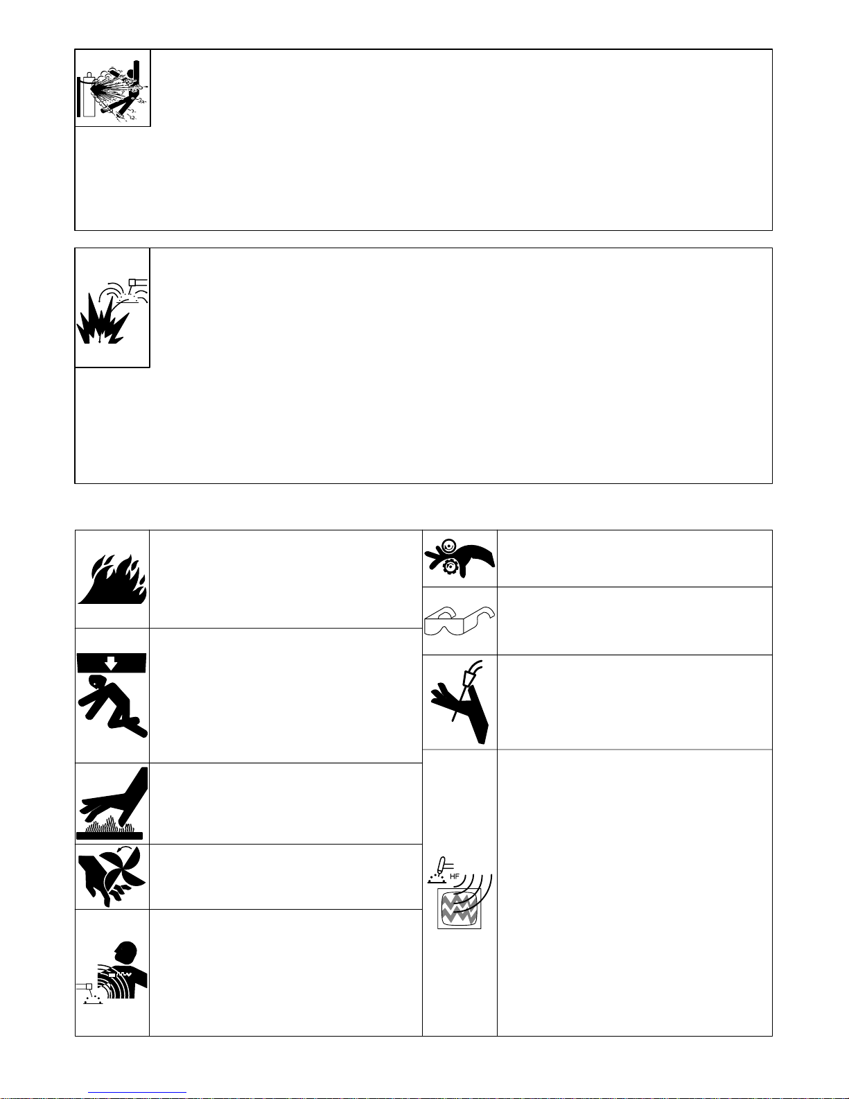
FLYING PIECES OF MET AL or DIRT can
injure eyes.
1. Wear safety glasses with side shields or face
shield.
WELDING WIRE can cause puncture
wounds.
1. Do not press gun trigger until instructed to do so.
2. Do not point gun toward any part of the body, other
people, or any metal when threading welding wire.
HIGH-FREQUENCY RADIATION can
interfere with radio navigation, safety
services, computers, and
communications equipment.
1. Have only qualified persons familiar with
electronic equipment perform this installation.
2. The user is responsible for having a qualified
electrician promptly correct any interference
problem resulting from the installation.
3. If notified by the FCC about interference, stop
using the equipment at once.
4. Have the installation regularly checked and
maintained.
5. Keep high-frequency source doors and panels
tightly shut, keep spark gaps at correct setting,
and use grounding and shielding to minimize the
possibility of interference.
OM-185 480 Page 2
Page 5

OVERUSE can cause OVERHEATED
EQUIPMENT.
1. Allow cooling period.
2. Reduce current or reduce duty cycle before
starting to weld again.
3. Follow rated duty cycle.
STATIC ELECTRICITY can damage parts
on circuit boards.
1. Put on grounded wrist strap BEFORE handling
boards or parts.
2. Use proper static-proof bags and boxes to store,
move, or ship PC boards.
1-4. Principal Safety Standards
SIGNIFICANT DC VOLTAGE exists after
removal of input power on inverters.
1. Turn Off inverter, disconnect input power, and
discharge input capacitors according to
instructions in Maintenance Section before
touching any parts.
BUILDUP OF SHIELDING GAS can harm
health or kill.
1. Shut of f shielding gas supply when not in use.
Safety in Welding and Cutting, ANSI Standard Z49.1, from
American Welding Society , 550 N.W . LeJeune Rd, Miami FL 33126
Safety and Health Standards, OSHA 29 CFR 1910, from
Superintendent of Documents, U.S. Government Printing Office,
Washington, D.C. 20402.
Recommended Safe Practices for the Preparation for Welding and
Cutting of Containers That Have Held Hazardous Substances,
American Welding Society Standard AWS F4.1, from American
Welding Society, 550 N.W. LeJeune Rd, Miami, FL 33126
National Electrical Code, NFPA Standard 70, from National Fire
Protection Association, Batterymarch Park, Quincy, MA 02269.
1-5. EMF Information
Considerations About Welding And The Effects Of Low Frequency
Electric And Magnetic Fields
The following is a quotation from the General Conclusions Section
of the U.S. Congress, Office of Technology Assessment, Biological
Effects of Power Frequency Electric & Magnetic Fields –
Background Paper, OTA-BP-E-53 (Washington, DC: U.S.
Government Printing Office, May 1989): “. . . there is now a very
large volume of scientific findings based on experiments at the
cellular level and from studies with animals and people which clearly
establish that low frequency magnetic fields can interact with, and
produce changes in, biological systems. While most of this work is of
very high quality, the results are complex. Current scientific
understanding does not yet allow us to interpret the evidence in a
single coherent framework. Even more frustrating, it does not yet
allow us to draw definite conclusions about questions of possible
risk or to o ffer clear science-based advice on strategies to minimize
or avoid potential risks.”
Safe Handling of Compressed Gases in Cylinders, CGA Pamphlet
P-1, from Compressed Gas Association, 1235 Jefferson Davis
Highway, Suite 501, Arlington, VA 22202.
Code for Safety in Welding and Cutting, CSA Standard W117.2,
from Canadian Standards Association, Standards Sales, 178
Rexdale Boulevard, Rexdale, Ontario, Canada M9W 1R3.
Safe Practices For Occupation And Educational Eye And Face
Protection, ANSI Standard Z87.1, from American National
Standards Institute, 1430 Broadway, New York, NY 10018.
Cutting And Welding Processes, NFPA Standard 51B, from
National Fire Protection Association, Batterymarch Park, Quincy,
MA 02269.
To reduce magnetic fields in the workplace, use the following
procedures:
1. Keep cables close together by twisting or taping them.
2. Arrange cables to one side and away from the operator.
3. Do not coil or drape cables around the body.
4. Keep welding power source and cables as far away as
practical.
5. Connect work clamp to workpiece as close to the weld as
possible.
About Pacemakers:
The above procedures are also recommended for pacemaker
wearers. Consult your doctor for complete information.
OM-185 480 Page 3
Page 6
SECTION 2 – INSTALLATION
2-1. Typical Process Connections
NOTE
Constant current and/or
constant voltage transformer
and engine-driven DC power
sources. If the power source
does not have a weld output
contactor, the optional
contactor kit should be
ordered.
Weld Power Cable (Not Included)
10 ft (3 m) Contactor Cord
10 ft (3 m) 115 VAC Power Cord
Use gun Owner’s Manual when making connections.
115 Volt
Control
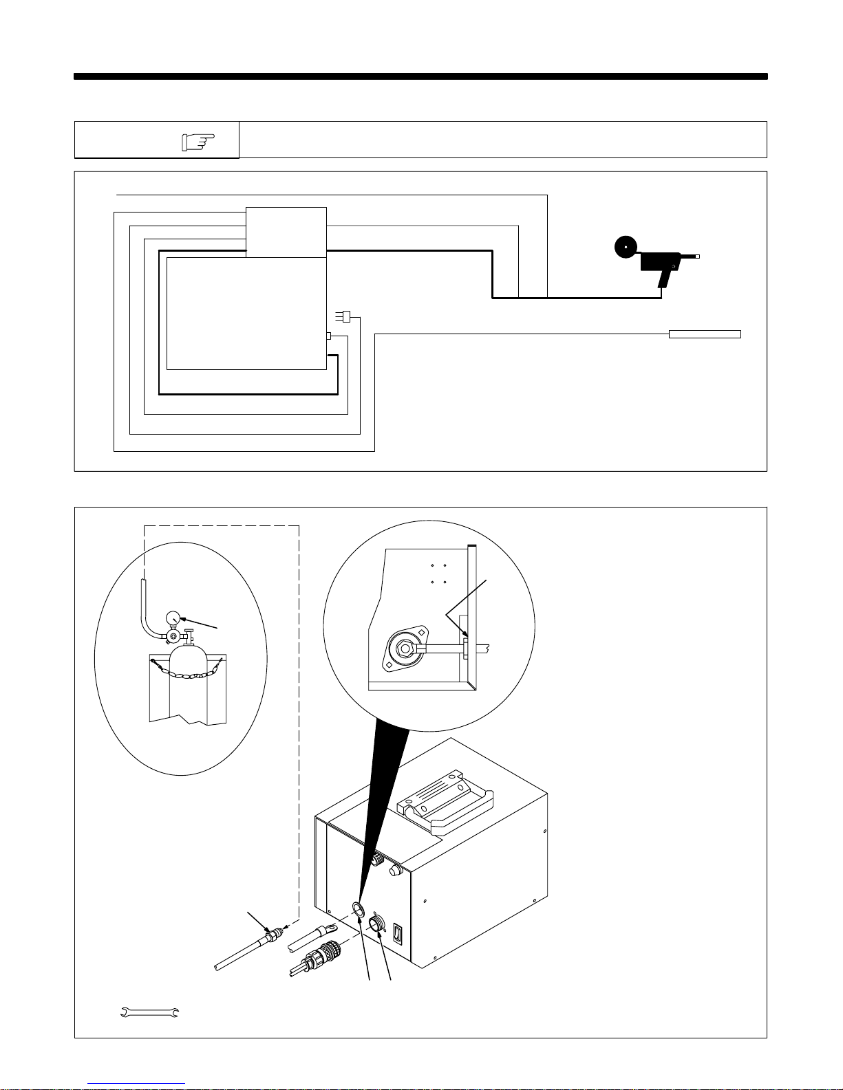
2-2. Gun/Feeder Connections
40 ft (12 m) Gas Hose
30 ft (9 m) Control Cord
30 ft (9 m) Weld Power Cable
Voltage Sensing Lead For CC Mode
Work
1 Gun Control Receptacle
2 Weld Power Grommet
3 Regulator/Flowmeter
2
4 Gas Fitting
Tools Needed:
3
5/8, 3/4 in
Left Side
Wrapper Off
4
1
2
Ref. ST-149 966-C / Ref. ST-149 549-B / Ref. S-0621-C
OM-185 480 Page 4
Page 7

2-3. Voltage Sensing Lead Connections And Motor Start Control Adjustment
1 Center Baffle
2 Circuit Board PC1
3 Jumper Plug
4 Receptacle RC3
Internal (INT) and external (EXT)
are stamped on PC1 just above
RC3. Unit is shipped with jumper
plug in internal (INT) position.
5 Potentiometer R70
6 Voltage Sensing Lead
Front
1
2
3
4
CV CC
INT. EXT.
123
RC3
For constant current welding
(CC), place jumper plug in the
EXT position. Connect voltage
sensing lead to workpiece.
For constant voltage welding (CV),
place jumper plug in the INT position. Do not connect voltage sensing lead.
To adjust motor ramp speed, remove protective cap (if present),
and adjust potentiometer R70 using a small nonconductive screwdriver. Rotating R70 clockwise increases the time it takes the motor
to ramp up to speed.
Reinstall wrapper.
For CC operation, connect
voltage sensing lead to
workpiece.
Tools Needed:
5
6
Work
Rear View
1/4 in
ST-801 840 / ST-150 035
OM-185 480 Page 5
Page 8

2-4. Weld Cable Connections
Rear View
1 Lower Left Grommet
2 Positive (+) Weld Output
Terminal On Welding Power
Source
3 Reed Switch
4 Weld Cable (Customer
Supplied)
5 Weld Cable Terminal
6 Weld Power Cable From
Gun/Feeder
7 Weld Power Grommet
1
8
Front Panel
Opening
Route weld cable and weld power
cable as shown. Be sure lug on
7
weld cable terminal and lug on gun/
feeder weld power cable make
contact with each other.
8 Contactor W1 (Optional)
Connect weld cable from welding
power source to unused W1
terminal.
Connect weld cable from W1 to
weld cable terminal.
Reinstall wrapper.
2
+–
Welding Power
Source
3 4 5 6
Tools Needed:
1/4 in
3/4 in
ST-801 840 / ST-151 113 / ST-801 487-A / Ref. SC-139 439-B
OM-185 480 Page 6
Page 9

2-5. Input Power Connection
1
2
3
4
2-6. Contact Closure Connections
A. 5-Pin Plug Information For Standard Contact Closure Connections
Pin* Pin Information
A Contact output signal.
E
DA
DA
CB
B Input control to energize weld contactor. Contact closure to A completes 24 volts ac contactor
control circuit.
1 Contact Closure
Interconnecting Cord And
Plug PLG5
2 Voltage Sensing Lead
Connect to workpiece for CC op-
eration (see Section 2-3).
3 Grounded Receptacle
A 15 ampere branch circuit pro-
tected by time-delay fuses or circuit breakers is required.
4 Input Power Cord And Plug
PLG4
Connect input power plug to a
proper receptacle.
ST-801 839
*The remaining pins are not used. Ref. S-0005-A
OM-185 480 Page 7
Page 10

SECTION 3 – OPERATION
3-1. 115 Volt Model Controls
1
1 Run-In Speed Control
Use control to select welding wire
speed before arc initiation. After
arc initiation, the wire feed speed is
controlled by the Wire Speed control on the gun/feeder.
2 Power Switch
Use switch to turn unit On and Off.
2
3-2. Shielding Gas
wfcontrols_1 1/96 / Ref. ST-144 451-D
1 Shielding Gas Cylinder
2 Valve
Open valve on cylinder just before
3
2
1
welding.
Close valve on cylinder when fin-
ished welding.
3 Regulator/Flowmeter
sb5.1* 6/92 – S-0621-C
OM-185 480 Page 8
Page 11

SECTION 4 – MAINTENANCE & TROUBLESHOOTING
Replace
Damaged Or
Unreadable
Labels
4-1. Overload Protection
Y Disconnect power
before maintaining.
3 Months
Clean
Tighten
Terminals
6 Months
Blow Out Or
Vacuum Inside
And
Weld
. Maintain more often
during severe conditions.
Replace Damaged
Gas Hose
Repair Or Replace
Cracked Cables
And Cords
1
Push And Turn
2
Pull Out And
Replace F1
If fuse F1 opens, the weld control
shuts down. To check or change
F1, proceed as follows:
1 Fuse Holder Cover
2 Fuse (See Parts List For
Fuse Size)
Push And Turn
Ref. ST-144 451-D / Ref. ST-800 185-A
OM-185 480 Page 9
Page 12

4-2. Troubleshooting
Trouble Remedy
Pressing gun trigger does not energize weld control or welding wire.
For models without optional contactor
control: Pressing gun trigger feeds
control: Pressing gun trigger feeds
wire but does not energize welding
wire.
Secure plug PLG4 in 115 volts ac receptacle (see Sections 2-5).
Secure gun plug in Gun Control receptacle RC3 on weld control (see Section 2-2).
Check fuse F1 and replace if necessary (see Section 4-1).
See Troubleshooting Section of gun and/or welding power source Owner’s Manual.
Secure plug PLG5 in 5 pin receptacle on welding power source (see Section 2-6).
See Troubleshooting Section of welding power source Owner’s Manual.
For models with optional contactor
control: Pressing gun trigger feeds
wire but does not energize welding
wire.
Pressing gun trigger energizes wire,
but wire does not feed.
Erratic weld output.
Wire feeds erratically. See Troubleshooting Section of gun Owner’s Manual.
Wire feed speed does not switch from
run-in speed to weld wire feed speed.
Wire feeds, but burns back. Readjust ramp-up speed potentiometer R70 on motor control board PC1 (see Section 2-3).
No gas flow. Check gas hose and connections, and replace if necessary (see Section 2-2).
Wire does not feed, and is not ener-
gized.
See Troubleshooting Section of welding power source Owner’s Manual.
See Troubleshooting Section of gun Owner’s Manual.
Secure plug PLG4 in 115 volts ac receptacle (see Sections 2-5).
Secure gun plug in Gun Control receptacle RC3 on weld control (see Section 2-2).
Secure plug PLG5 in 5 pin receptacle on welding power source (see Section 2-6).
See Troubleshooting Section of gun and/or welding power source Owner’s Manual.
Check reed relay, and replace if necessary.
Connect voltage sensing lead to workpiece (see Section 2-3).
OM-185 480 Page 10
Page 13

SECTION 5 – ELECTRICAL DIAGRAM
SC-155 058-B
Figure 5-1. Circuit Diagram
OM-185 480 Page 11
Page 14

SECTION 6 – PARTS LIST
13
17
16
15
21
11
12 14
8
9 10
1819
23
22
25
20
24
26
32
33
27
28
29
30
31
34
6 7
40
4 5
3
1 2
41
39
38
35
34
36
37
ST-801 837
Figure 6-1. Complete Assembly Of HWC-115A
OM-185 480 Page 12
Page 15

Item
No.
Dia.
Mkgs.
Part
No.
Description Quantity
Figure 6-1. Complete Assembly Of HWC-115A
1 126 415 CLAMP, saddle 1. . . . . . . . . . . . . . . . . . . . . . . . . . . . . . . . . . . . . . . . . . . . . . . . . . . . . . . . . . . . . . . . . . . . .
2 126 416 HANDLE 1. . . . . . . . . . . . . . . . . . . . . . . . . . . . . . . . . . . . . . . . . . . . . . . . . . . . . . . . . . . . . . . . . . . . . . . . . . .
3 +137 834 COVER, control box 1. . . . . . . . . . . . . . . . . . . . . . . . . . . . . . . . . . . . . . . . . . . . . . . . . . . . . . . . . . . . . . . .
4D1♦142 266 DIODE 1. . . . . . . . . . . . . . . . . . . . . . . . . . . . . . . . . . . . . . . . . . . . . . . . . . . . . . . . . . . . . . . . . . . . . . .
5W1♦192 809 CONTACTOR, 12VDC 1PST 1. . . . . . . . . . . . . . . . . . . . . . . . . . . . . . . . . . . . . . . . . . . . . . . . . . .
6 ♦111 153 SPACER, contactor 1. . . . . . . . . . . . . . . . . . . . . . . . . . . . . . . . . . . . . . . . . . . . . . . . . . . . . . . . . . . . . . . . .
7 ♦142 257 INSULATOR, contactor 1. . . . . . . . . . . . . . . . . . . . . . . . . . . . . . . . . . . . . . . . . . . . . . . . . . . . . . . . . . . . .
8 REED 140 786 SWITCH, reed 1. . . . . . . . . . . . . . . . . . . . . . . . . . . . . . . . . . . . . . . . . . . . . . . . . . . . . . . . . . . . . . .
9 134 201 STAND-OFF SUPPORT, PC card .312/.375 4. . . . . . . . . . . . . . . . . . . . . . . . . . . . . . . . . . . . . . . . . . . .
10 R1 073 562 POTENTIOMETER, C std slot 1/T 2W 10K ohm 1. . . . . . . . . . . . . . . . . . . . . . . . . . . . . . . . . .
11 070 371 BLANK, snap-in nyl 1.093/1.125mtg hole 1. . . . . . . . . . . . . . . . . . . . . . . . . . . . . . . . . . . . . . . . . . . . .
12 057 358 BUSHING, snap-in nyl 1.000 ID x 1.375mtg hole 1. . . . . . . . . . . . . . . . . . . . . . . . . . . . . . . . . . . . . .
13 PC1 137 492 CIRCUIT CARD, WC voltage sensing motor 1. . . . . . . . . . . . . . . . . . . . . . . . . . . . . . . . . . . . .
PLG1 115 094 CONNECTOR & SOCKETS (RC1) 1. . . . . . . . . . . . . . . . . . . . . . . . . . . . . . . . . . . . . . . . . . . . . . . .
PLG2 115 091 CONNECTOR & SOCKETS (RC2) 1. . . . . . . . . . . . . . . . . . . . . . . . . . . . . . . . . . . . . . . . . . . . . . . .
PLG50 ♦135 788 CONNECTOR & SOCKETS 1. . . . . . . . . . . . . . . . . . . . . . . . . . . . . . . . . . . . . . . . . . . . . . . . . . . .
14 138 044 BUSHING, strain relief .120/.150 ID x .500mtg hole 1. . . . . . . . . . . . . . . . . . . . . . . . . . . . . . . . . . . .
15 600 848 WIRE, strd 12ga (order by ft) 35ft. . . . . . . . . . . . . . . . . . . . . . . . . . . . . . . . . . . . . . . . . . . . . . . . . . . . . .
16 601 226 INSULATOR, vinyl clamp univ 25A black 1. . . . . . . . . . . . . . . . . . . . . . . . . . . . . . . . . . . . . . . . . . . . .
17 601 228 CLAMP, univ 25A 1. . . . . . . . . . . . . . . . . . . . . . . . . . . . . . . . . . . . . . . . . . . . . . . . . . . . . . . . . . . . . . . . .
18 PLG5 185 858 CONNECTOR, circ 5 pin sz 18 1. . . . . . . . . . . . . . . . . . . . . . . . . . . . . . . . . . . . . . . . . . . . . . .
19 600 340 CABLE, port No. 16 2/c (order by ft) 11ft. . . . . . . . . . . . . . . . . . . . . . . . . . . . . . . . . . . . . . . . . . . . . . . .
20 PLG4 139 627 CORD SET, pwr 125V 16ga 3/c 10ft 6 in 1. . . . . . . . . . . . . . . . . . . . . . . . . . . . . . . . . . . . . .
21 139 042 BUSHING, strain relief .270/.480 ID x .804mtg hole 2. . . . . . . . . . . . . . . . . . . . . . . . . . . . . . . . . . . .
22 135 736 WASHER, flat rbr .812 ID x 1.125 OD x .031thk 2. . . . . . . . . . . . . . . . . . . . . . . . . . . . . . . . . . . . . . .
23 1T 038 783 BLOCK, term 20A 12P 1. . . . . . . . . . . . . . . . . . . . . . . . . . . . . . . . . . . . . . . . . . . . . . . . . . . . . . . . . .
601 219 LINK, jumper term blk 20A 2. . . . . . . . . . . . . . . . . . . . . . . . . . . . . . . . . . . . . . . . . . . . . . . . . . . . . . . . . . . . .
24 SR2 035 704 RECTIFIER, integ 40A 800V 1. . . . . . . . . . . . . . . . . . . . . . . . . . . . . . . . . . . . . . . . . . . . . . . . . . .
25 SR1 ♦035 704 RECTIFIER, integ 40A 800V 1. . . . . . . . . . . . . . . . . . . . . . . . . . . . . . . . . . . . . . . . . . . . . . . . . .
26 ♦155 183 BRACKET, mtg cmpnt 1. . . . . . . . . . . . . . . . . . . . . . . . . . . . . . . . . . . . . . . . . . . . . . . . . . . . . . . . . . . .
27 T1 090 465 TRANSFORMER, signal 115V 24VCT 4A 1. . . . . . . . . . . . . . . . . . . . . . . . . . . . . . . . . . . . . . . . .
28 D2-4 155 057 DIODE 3. . . . . . . . . . . . . . . . . . . . . . . . . . . . . . . . . . . . . . . . . . . . . . . . . . . . . . . . . . . . . . . . . . . . . .
29 139 408 STRIP, mtg relay 1. . . . . . . . . . . . . . . . . . . . . . . . . . . . . . . . . . . . . . . . . . . . . . . . . . . . . . . . . . . . . . . . . .
30 CR1 052 964 RELAY, encl 24VDC DPDT 1. . . . . . . . . . . . . . . . . . . . . . . . . . . . . . . . . . . . . . . . . . . . . . . . . . . .
31 CR2,3 116 592 RELAY, encl 24VDC 3PDT 2. . . . . . . . . . . . . . . . . . . . . . . . . . . . . . . . . . . . . . . . . . . . . . . . . . .
120 304 BLANK, snap-in nyl .250mtg hole 1. . . . . . . . . . . . . . . . . . . . . . . . . . . . . . . . . . . . . . . . . . . . . . . . . . . . . . .
057 359 BLANK, snap-in nyl .375mtg hole 2. . . . . . . . . . . . . . . . . . . . . . . . . . . . . . . . . . . . . . . . . . . . . . . . . . . . . . .
107 983 BLANK, snap-in nyl .500mtg hole 1. . . . . . . . . . . . . . . . . . . . . . . . . . . . . . . . . . . . . . . . . . . . . . . . . . . . . . .
32 RC3 139 268 CONNECTOR, circ 10skt rcpt 1. . . . . . . . . . . . . . . . . . . . . . . . . . . . . . . . . . . . . . . . . . . . . . . . . .
33 025 590 MOUNT, resilient 4. . . . . . . . . . . . . . . . . . . . . . . . . . . . . . . . . . . . . . . . . . . . . . . . . . . . . . . . . . . . . . . . . .
34 046 432 HOLDER, fuse mintr 1. . . . . . . . . . . . . . . . . . . . . . . . . . . . . . . . . . . . . . . . . . . . . . . . . . . . . . . . . . . . . . .
35 F1 *012 658 FUSE, mintr gl slo-blo 2A 125V 1. . . . . . . . . . . . . . . . . . . . . . . . . . . . . . . . . . . . . . . . . . . . . . . . . .
36 S1 111 997 SWITCH, rocker SPST 10A 250VAC 1. . . . . . . . . . . . . . . . . . . . . . . . . . . . . . . . . . . . . . . . . . . . . . .
37 057 357 BUSHING, snap-in nyl .937 ID x 1.125mtg hole 1. . . . . . . . . . . . . . . . . . . . . . . . . . . . . . . . . . . . . . .
38 097 922 KNOB, pointer 1. . . . . . . . . . . . . . . . . . . . . . . . . . . . . . . . . . . . . . . . . . . . . . . . . . . . . . . . . . . . . . . . . . . .
39 NAMEPLATE, (order by model and serial number) 1. . . . . . . . . . . . . . . . . . . . . . . . . . . . . . . . . . . . . . . . . . . . . .
039 041 TERMINAL, pwr output red (consisting of) 1. . . . . . . . . . . . . . . . . . . . . . . . . . . . . . . . . . . . . . . . . . . . . . . .
039 049 TERMINAL BOARD, red 1. . . . . . . . . . . . . . . . . . . . . . . . . . . . . . . . . . . . . . . . . . . . . . . . . . . . . . . . . . . . . .
147 880 SCREW, cap stl hexhd .500-13 x 1.500 1. . . . . . . . . . . . . . . . . . . . . . . . . . . . . . . . . . . . . . . . . . . . . . . . .
602 247 WASHER, flat stl SAE .500 1. . . . . . . . . . . . . . . . . . . . . . . . . . . . . . . . . . . . . . . . . . . . . . . . . . . . . . . . . . . .
601 880 NUT, stl hex jam .500-13 1. . . . . . . . . . . . . . . . . . . . . . . . . . . . . . . . . . . . . . . . . . . . . . . . . . . . . . . . . . . . . .
601 879 NUT, stl hex full fnsh .500-13 1. . . . . . . . . . . . . . . . . . . . . . . . . . . . . . . . . . . . . . . . . . . . . . . . . . . . . . . . . . .
40 177 131 CHASSIS, control box 1. . . . . . . . . . . . . . . . . . . . . . . . . . . . . . . . . . . . . . . . . . . . . . . . . . . . . . . . . . . . .
41 176 254 LABEL, warning general precautionary CE 1. . . . . . . . . . . . . . . . . . . . . . . . . . . . . . . . . . . . . . . . . . .
134 327 LABEL, warning general precautionary static 1. . . . . . . . . . . . . . . . . . . . . . . . . . . . . . . . . . . . . . . . . . . . .
+When ordering a component originally displaying a precautionary label, the label should also be ordered.
♦Part of 137 547 Contactor Kit Option.
*Recommended Spare Parts.
BE SURE TO PROVIDE MODEL AND SERIAL NUMBER WHEN ORDERING REPLACEMENT PARTS.
OM-185 480 Page 13
Page 16

Notes
123
123
Page 17

Notes
123
123
Page 18

Notes
123
123
Page 19

Warranty Questions?
Call
1-877-HOBART1
for your local
Hobart distributor.
Service
Y ou always get the fast,
reliable response you
need. Most replacement
parts can be in your
hands in 24 hours.
Support
Need fast answers to the
tough welding questions?
Contact your distributor or
call 1-800-332-3281. The
expertise of the distributor
and Hobart is there to
help you, every step of
the way.
Effective January 1, 2000
(Equipment with a serial number preface of “LA” or newer)
This limited warranty supersedes all previous Hobart warranties and is exclusive with no other
LIMITED WARRANTY – Subject to the terms and conditions
below, Hobart Welding Products., Troy, Ohio, warrants to its
original ret a i l p urchaser that new Hobart equipment sold after
the effective date of this limited warranty is free of defects in
material and workmanship at the time it is shipped by Hobart.
THIS WARRANTY IS EXPRESSL Y IN LIEU OF ALL OTHER
WARRANTIES, EXPRESS OR IMPLIED, INCLUDING THE
WARRANTIES OF MERCHANTABILITY AND FITNESS.
Within the warranty periods listed below, Hobart will repair or
replace any warranted parts or components that fail due to
such defects in material or workmanship. Hobart must be
notified in writing within thirty (30) days of such defect or
failure, at which time Hobart will provide instructions on the
warranty claim procedures to be followed.
Hobart shall honor warranty claims on warranted equipment
listed below in the event of such a failure within the warranty
time periods. All warranty time periods start on the date that
the equipment was delivered to the original retail purchaser, or
one year after the equipment is sent to a North American
distributor or e i ghteen months after the equipment is sent to an
International distributor.
1. 5 Years Parts – 3 Years Labor
* Original main power rectifiers
* Inverters (input and output rectifiers only)
2. 3 Years — Parts and Labor
* Transformer/Rectifier Power Sources
* Plasma Arc Cutting Power Sources
* Semi-Automatic and Automatic Wire Feeders
* Inverter Power Supplies
* Intellitig
* Engine Driven Welding Generators
(NOTE: Engines are warranted separately by
the engine manufacturer .)
3. 1 Year — Parts and Labor
* DS-2 Wire Feeder
* Motor Driven Guns (w/exception of Spoolmate
185 & Spoolmate 250)
* Process Controllers
* Positioners and Controllers
* Automatic Motion Devices
* RFCS Foot Controls
* Induction Heating Power Sources
* Water Coolant Systems
* HF Units
* Grids
* Maxstar 140
* Spot Welders
* Load Banks
* Hobart Cyclomatic Equipment
* Running Gear/Trailers
* Plasma Cutting Torches (except APT & SAF
Models)
* Field Options
(NOTE: Field options are covered under True
Blue for the remaining warranty period of the
product they are installed in, or for a minimum of
one year — whichever is greater.)
4. 6 Months — Batteries
5. 90 Days — Parts
* MIG Guns/TIG Torches
* Induction Heating Coils and Blankets
guarantees or warranties expressed or implied.
* APT, ZIPCUT & PLAZCUT Model Plasma Cutting
Torches
* Remote Controls
* Accessory Kits
* Replacement Parts (No labor)
* Spoolmate 185 & Spoolmate 250
* Canvas Covers
HOBART’s Limited Warranty shall not apply to:
1. Consumable components; such as contact tips,
cutting nozzles, contactors, brushes, slip rings,
relays or parts that fail due to normal wear.
2. Items furnished by Hobart, but manufactured by others,
such as engines or trade accessories. These items are
covered by the manufacturer’s warranty, if any.
3. Equipment that has been modified by any party other
than Hobart, or equipment that has been improperly
installed, improperly operated or misused based upon
industry standards, or equipment which has not had
reasonable and necessary maintenance, or equipment
which has been used for operation outside of the
specifications for the equipment.
HOBART PRODUCTS ARE INTENDED FOR PURCHASE
AND USE BY COMMERCIAL/INDUSTRIAL USERS AND
PERSONS TRAINED AND EXPERIENCED IN THE USE
AND MAINTENANCE OF WELDING EQUIPMENT.
In the event of a warranty claim covered by this warranty, the
exclusive remedies shall be, at Hobart’s option: (1) repair; or
(2) replacement; or, where authorized in writing by Hobart in
appropriate cases, (3) the reasonable cost of repair or
replacement at an authorized Hobart service station; or (4)
payment of or credit for the purchase price (less reasonable
depreciation bas e d u p o n actual use) upon return of the goods
at customer’s risk and expense. Hobart’s option of repair or
replacement will be F.O.B., Factory at Appleton, Wisconsin, or
F.O.B. at a Hobart authorized service facility as determined by
Hobart. Therefore no compensation or reimbursement for
transportation costs of any kind will be allowed.
TO THE EXTENT PERMITTED BY LAW, THE REMEDIES
PROVIDED HEREIN ARE THE SOLE AND EXCLUSIVE
REMEDIES. IN NO EVENT SHALL HOBART BE LIABLE
FOR DIRECT, INDIRECT, SPECIAL, INCIDENTAL OR
CONSEQUENTIAL DAMAGES (INCLUDING LOSS OF
PROFIT), WHETHER BASED ON CONTRACT, TORT OR
ANY OTHER LEGAL THEORY.
ANY EXPRESS WARRANTY NOT PROVIDED HEREIN
AND ANY IMPLIED WARRANTY, GUARANTY OR
REPRESENTATION AS TO PERFORMANCE, AND ANY
REMEDY FOR BREACH OF CONTRACT TORT OR ANY
OTHER LEGAL THEORY WHICH, BUT FOR THIS
PROVISION, MIGHT ARISE BY IMPLICATION,
OPERATION OF LAW, CUSTOM OF TRADE OR COURSE
OF DEALING, INCLUDING ANY IMPLIED WARRANTY OF
MERCHANTABILITY OR FITNESS FOR PARTICULAR
PURPOSE, WITH RESPECT TO ANY AND ALL
EQUIPMENT FURNISHED BY HOBART IS EXCLUDED
AND DISCLAIMED BY HOBART.
Some states in the U.S.A. do not allow limitations of how long
an implied warranty lasts, or the exclusion of incidental,
indirect, special or consequential damages, so the above
limitation or exclusion may not apply to you. This warranty
provides specific legal rights, and other rights may be
available, but may vary from state to state.
In Canada, legislation in some provinces provides for certain
additional warranties or remedies other than as stated herein,
and to the extent that they may not be waived, the limitations
and exclusions set out above may not apply. This Limited
Warranty provides specific legal rights, and other rights may
be available, but may vary from province to province.
hobart standard 7/00
Page 20

Owner’s Record
Please complete and retain with your personal records.
Model Name Serial/Style Number
Purchase Date (Date which equipment was delivered to original customer.)
Distributor
Address
City
State Zip
Resources Available
Always provide Model Name and Serial/Style Number.
To locate a Distributor,
retail or service location:
Call 1-877-Hobart1 or visit our website at
www.HobartWelders.com
For technical assistance:
Call 1-800-332-3281
Contact the Delivering Carrier for:
For assistance in filing or settling claims,
contact your distributor and/or equipment
manufacturer’s Transportation Department.
Contact your Distributor for:
Welding Supplies and Consumables
Options and Accessories
Personal Safety Equipment
Service and Repair
Replacement Parts
Training (Schools, Videos, Books)
Technical Manuals (Servicing Information
and Parts)
Circuit Diagrams
Welding Process Handbooks
File a claim for loss or damage during
shipment.
Hobart Welding Products
An Ill inoi s Tool Works Company
600 West Main Street
Troy, OH 45373 USA
For Technical Assistance:
Call1-800-332-3281
For Literature Or Nearest Dealer:
Call 1-877-Hobart1
PRINTED IN USA 2001 Hobart Welding Products. 1/01
 Loading...