


I
N
S
T
R
U
C
HUV SERIES DELI DISPLAY CASES
MODELS
T
I
O
N
S
HUV3P ML-132065 (3-PAN, FULL-SERVICE)
ML-132066 (3-PAN, SELF-SERVICE)
HUV4P ML-132067 (4-PAN, FULL-SERVICE)
ML-132068 (4-PAN, SELF-SERVICE)
HUV5P ML-132069 (5-PAN, FULL-SERVICE)
ML-132070 (5-PAN, SELF-SERVICE)
HUV3P/2 ML-132071 (3-PAN FULL-SERVICE/2-PAN SELF-SERVICE)
701 S. RIDGE AVENUE
TROY, OHIO 45374-0001
937 332-3000
www.hobartcorp.com
FORM 34852 (Jan. 2003)

TABLE OF CONTENTS
GENERAL .............................................................................................................................................3
INSTALLATION ....................................................................................................................................4
Unpacking .......................................................................................................................................4
ASSEMBLY ...........................................................................................................................................5
Installation of the Side and Center Glass Panels .........................................................................5
Raise the Front Glass (Customer Side) ........................................................................................ 5
Install the Glass Panels..................................................................................................................5
Installation of the Glass Seal Strips ............................................................................................... 6
Lower the Front Glass (Customer Side)........................................................................................6
Installation of the Sliding Glass Doors...........................................................................................7
Installation of the Adjustable Frame and Trays (Full-Service or Full-Service Section Only)..... 7
Installation of the Food Temperature Probe and Holder (Optional) .............................................8
Installation of the Cutting Board (Optional) ...................................................................................8
Installation of the Base (Optional)..................................................................................................8
Location ...........................................................................................................................................9
Installation Codes and Standards ..................................................................................................9
Electrical Connection ................................................................................................................... 10
Plumbing Connection ................................................................................................................... 11
Water Quality ............................................................................................................................... 11
Drain Connection ......................................................................................................................... 12
Before First Use........................................................................................................................... 12
OPERATION...................................................................................................................................... 13
Power On Display Case (Full-Service) ...................................................................................... 14
Automatic Water Level Fill........................................................................................................... 14
Programming the Upper Heater Settings (Full-Service)............................................................ 15
Programming the Well Temperature (Full-Service).................................................................... 16
Programming the Humidity Tray Heater Setting (Full-Service)................................................. 16
Memory (Full-Service) ................................................................................................................. 17
Preheat (Full-Service) ................................................................................................................. 17
Loading Food Product into the Display Case (Full-Service) ..................................................... 18
Using the Optional Food Probe ................................................................................................... 18
Power on Display Case (Self-Service)....................................................................................... 20
Programming the Well Temperature (Self-Service) ................................................................... 20
Memory (Self-Service)................................................................................................................. 21
Preheat (Self-Service) ................................................................................................................. 21
Loading Food Product into Display Case (Self-Service) ........................................................... 21
Operation Combination (Full/Self-Service)................................................................................. 22
SHUTDOWN...................................................................................................................................... 22
End of the Day ............................................................................................................................. 22
CLEANING......................................................................................................................................... 23
Cleaning the Food Probe ............................................................................................................. 23
End of Day.................................................................................................................................... 23
Monthly ......................................................................................................................................... 25
MAINTENANCE................................................................................................................................. 26
TROUBLESHOOTING...................................................................................................................... 26
Self-Service Case ........................................................................................................................ 26
Full-Service Cases ...................................................................................................................... 27
– 2 –

INSTALLATION, OPERATION AND CARE OF
HUV SERIES DELI DISPLAY CASES
SAVE THESE INSTRUCTIONS
GENERAL
The HUV, Hobart Ultra-View, series of deli display cases hold hot food products at regulated
temperatures maintaining both freshness and quality. The display cases feature electronic temperature
regulation of the well heat and air stream. Full-Service cases include upper zonal adjustment of heat
and humidity. Quality stainless steel and clear/mirrored tempered glass and 0 to 10 degree adjustable
pan frame provide the customer with an Ultra-View of hot deli products.
Self-Service cases provide an opening to permit the customer to get it and go. Combinations of HUV3P,
HUV4P, HUV5P and HUV3P/2 can be placed next to each other to provide a variety of pan
configurations. Display cases can accept all standard size pans.
As options, the display case can be mounted on a base, equipped with a cutting board or an optional
food probe.
Proper installation, usage, and maintenance of your deli display case is important. Please read this
entire manual and carefully follow all of the instructions provided.
– 3 –

INSTALLATION
Before installing, check the electrical service to make sure it agrees with the specifications on the
machine data plate, located on the operator side of the display case.
UNPACKING
Immediately after unpacking the deli display case, check for possible shipping damage. If the deli
display case is found to be damaged, save the packaging material and contact the carrier within 15 days
of delivery.
Remove all vinyl paper from the stainless steel surfaces of the display case and any tape from the glass
and steel surfaces.
Unpack the parts that need to be assembled:
HUV3P/2 HUV3P HUV3P HUV4P HUV4P HUV5P HUV5P
Full/Self- Full- Self- Full- Self- Full- Self-
Service Service Service Service Service Service Service
Parts shipped inside the unit and packed separately
Center divider glass panel 1 N/A N/A N/A N/A N/A N/A
Side glass panels 2 2 2 2 2 2 2
Black glass seal strips 2 2 N/A 2 N/A 2 N/A
Sliding doors 4 2 2 2 2 2 2
Long divider bars 1 1 N/A 1 N/A 1 N/A
Medium divider bars 2 2 N/A 3 N/A 4 N/A
Short divider bars 2 2 N/A 3 N/A 4 N/A
Parts shipped separately (optional)
Painted Base Assy:
(assembly instructions 1 1 1 1 1 1 1
included in Base Assy.)
Cutting Board Assy: 1 1 N/A 1 N/A 1 N/A
Food Probe Assy:
Food Probe 1 1 N/A 1 N/A 1 N/A
Holder 1 1 N/A 1 N/A 1 N/A
– 4 –

ASSEMBLY
INSTALLATION OF THE SIDE AND CENTER GLASS PANELS
CAUTION: Handle glass panels with care to avoid breakage. The side and center glass panels
are tempered safety glass. If the edges of the glass panels scrape against stainless steel,
concrete or other hard surfaces, breakage may occur.
NOTE: Proper installation of the glass seal strips on FULL-service cases (or the FULL-service portion
of the display case) is important to maintain proper heat and humidity levels inside the FULL-service
portion of the display case. Glass seal strips are not required on SELF-SERVICE cases (or the SELFservice portion of the display case).
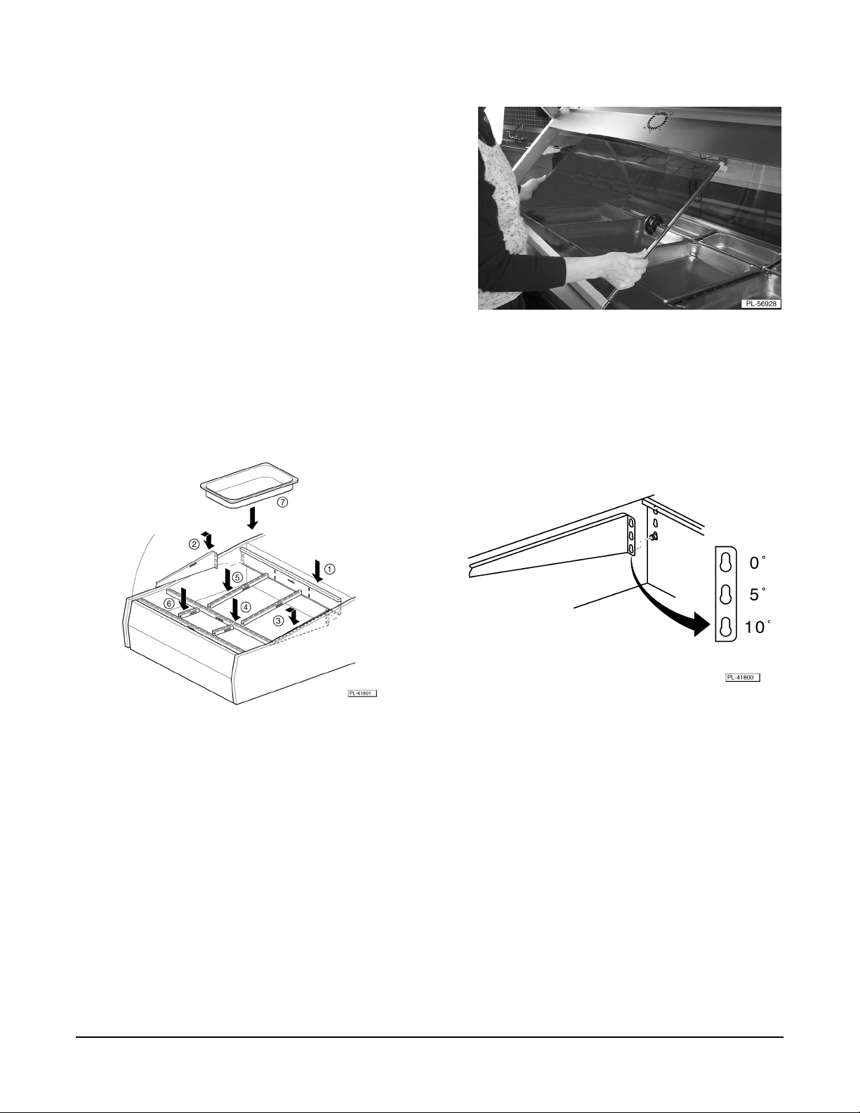
RAISE THE FRONT GLASS (CUSTOMER SIDE)
• Raise the front glass (customer side). The door is easier to open when held on the corner and
pulled up. Glass stays up by itself.
INSTALL THE GLASS PANELS
1. Position the side of glass panel in the groove on the
LEFT side of the case (Fig. 1).
2. Carefully slide the side glass panel toward the rear
(operator side) of the display case taking care to
avoid breakage.
3. Ensure the side glass is completely seated and held
in place by the angled track in the rear of the case.
4. Repeat steps 1 through 3 for the RIGHT side of the
case.
5. HUV3P/2 only: repeat steps 1 through 3 for the
CENTER of the case to divide the full-service and
self-service portions of the case.
Fig. 1
– 5 –

INSTALLATION OF THE GLASS SEAL STRIPS
NOTE: The black rubber strips seal the side glass to the front glass. They are necessary to hold
humidity and heat in the full-service (or Full-Service portions) of the case. It is important that the lip of
the rubber seal strip faces toward the inside of the Full-Service portion of the case (Fig. 2).
Fig. 2 Fig. 3
• Full-Service portion of the combination case: Install the black glass seal strip on the LEFT
side and CENTER glass panels (Fig. 3). Make sure the lip of the glass seal strips face toward
the inside of FULL-SERVICE portion of the case.
The RIGHT side glass panel does not require a glass seal strip.
Full-Service case: Install the black glass seal strip on the LEFT side and RIGHT glass panels.
•
Make sure the lip of the glass seal strips faces toward the inside of the case (Fig. 4).
Self-Service case: The black glass seal strip is not necessary (Fig.5).
•
Fig. 4 Fig. 5
LOWER THE FRONT GLASS (CUSTOMER SIDE)
• Lower the front glass (customer side).
– 6 –
INSTALLATION OF THE SLIDING GLASS DOORS
1. Insert the top of either door in the top inner track
(Fig. 6).
2. Place the bottom of the first door onto the bottom
inner track.
3. Insert the top of the second door in the top outer
track.
4. Place the bottom of the second door onto the
bottom outer track.
Fig. 6
INSTALLATION OF THE ADJUSTABLE FRAME AND TRAYS (FULL-SERVICE OR FULLSERVICE SECTION ONLY)
Fig. 7 Fig. 8
1. Adjust the back wall support to the 0, 5 or 10 degree position (FigS. 7 and 8).
2. Adjust the side wall support to the same 0, 5 or 10 degree position on LEFT side of the unit (Figs. 7
and 8).
3. Adjust the side wall support to the same 0, 5 or 10 degree position on RIGHT side of the unit
(Figs. 7 and 8).
4. Install the long divider bar as shown (Fig. 7).
5. Install the medium divider bars as shown (Fig. 7).
6. Install the short divider bars as shown (Fig. 7).
7. Install the pans between the divider bars as shown (Fig. 7).
– 7 –
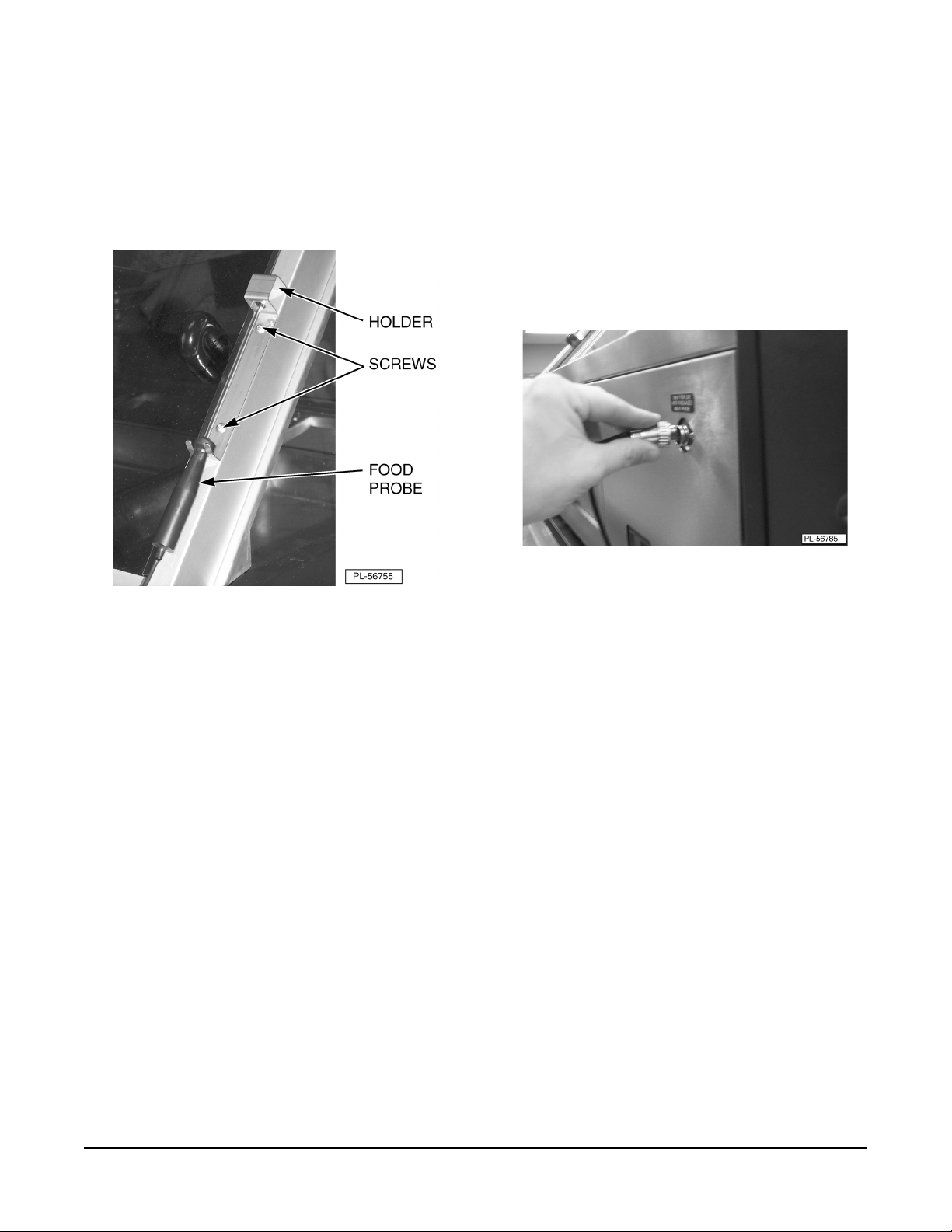
INSTALLATION OF THE FOOD TEMPERATURE PROBE AND HOLDER (OPTIONAL)
1. Mount the holder to the right-hand frame on the operator's side of the display case with two screws
(Fig 9).
2. Connect the food temperature probe by plugging probe into socket and twisting until locked into
place (Fig. 10).
3. Place the food temperature probe in the holder when not used (Fig. 9).
Fig. 9 Fig. 10
INSTALLATION OF THE CUTTING BOARD (OPTIONAL)
1. Assemble the cutting board onto the display case using the instructions provided with the cutting
board assembly.
INSTALLATION OF THE BASE (OPTIONAL)
1. Assemble the base using the instructions provided with the base assembly.
– 8 –

LOCATION
The installation location must allow adequate clearances for servicing and for proper operation.
INSTALLATION CODES AND STANDARDS
The HUV series of display cases must be installed according to the following codes:
In the United States of America:
1. State and local codes.
2. National Electric Code, ANSI/NFPA 70 (latest edition). Copies may be obtained from the National
Fire Protection Association, Batterymarch Park, Quincy, MA 02269.
In Canada:
1. Local codes.
2. Canadian Electric Code, CSA C22.1 (latest edition). Copies may be obtained from the Canadian
Standard Association, 5060 Spectrum Way, Suite 100, Mississauga, Ontario, Canada L4W 5N6.
– 9 –

ELECTRICAL CONNECTION
WARNING: ELECTRICAL AND GROUNDING CONNECTIONS MUST COMPLY WITH THE
APPLICABLE PORTIONS OF THE NATIONAL ELECTRICAL CODE AND/OR OTHER LOCAL
ELECTRICAL CODES.
ELECTRICAL DATA
LEDOMEPYTESAHP/ZH/STLOVSPMA
1/06/8028.62
P3VUHecivreS-lluF
P3VUHecivreS-fleS
P4VUHecivreS-lluF
P4VUHecivreS-fleS
3/06/8026.81
1/06/0428.52
3/06/0423.81
1/06/8026.71
3/06/8029.51
1/06/0424.71
3/06/0426.51
1/06/8026.72
3/06/8026.81
1/06/0429.62
3/06/0422.81
1/06/8026.81
3/06/8026.61
1/06/0425.81
3/06/0423.61
P5VUHecivreS-lluF
P5VUHecivreS-fleS
2/P3VUHecivreS-fleS/-lluF
1/06/8021.82
3/06/8026.81
1/06/0421.82
3/06/0423.81
1/06/8028.91
3/06/8025.71
1/06/0428.91
3/06/0425.71
1/06/8029.43
3/06/8023.22
1/06/0424.23
3/06/0422.02
– 10 –

PLUMBING CONNECTION
Water Supply Connection
WARNING: PLUMBING CONNECTIONS MUST COMPLY WITH APPLICABLE SANITARY, SAFETY
AND PLUMBING CODES.
1. Connect the water supply line. Connect water supply to the
(Fig. 11). Or remove adapter and connect water supply to the
1
/2-in.barbed type tubing connection
3
/4-in. NSHT (National Straight Hose
Thread) inlet (Fig. 12).
2. A manual shutoff valve should be provided convenient to the display case. This valve should be
open when the display case is in operation.
3. Water pressure should be 20 to 60 psi. If pressure is in excess of 60 psi, a pressure reducing valve
must be installed.
Fig. 11 Fig. 12
WATER QUALITY
Water supplies vary from one location to another. A local water treatment specialist should be consulted
and the water supply should be analyzed to make sure specifications are met before installing the
display case.
WATER SUPPLY SPECIFICATIONS
erusserPylppuSisp06ot02
ssendraHnollagrepsniarg4ot2
sedirolhCmpp03nahtsseL
sdiloSdevlossiDlatoTmpp06
egnaRHP8ot7
Untreated water contains scale-producing minerals which can build up on the water level sensor probe
and the humidity tray. Excess lime scale build up on water level sensor probes will cause an error in
the automatic water fill and the humidity tray may not fill with water.
The water-level sensor in the display case uses ions in the water to detect the water level. Do not use
distilled (fully de-mineralized or de-ionized) water. This could provide a false reading to the sensors and
overflow the humidity tray.
– 11 –

DRAIN CONNECTION
CAUTION: In order to avoid any back pressure in the display case, do not connect solidly to any
drain connection.
1. Connect an overflow drain line to the outlet using
1
/2 -in. I.D. size plastic tubing and a 1/2 -in. size hose
clamp. The
1
/2 -in. O.D.-size outlet is located on the
underside of the display case (Fig. 13).
Run drain tube to an open gap type drain (maximum
of 5 to 10 feet away). The drain tubing must have
appropriate support along its length. The drain line
from the display case must not be combined with any
drain line from another device.
Fig. 13
BEFORE FIRST USE
WARNING: DISCONNECT THE ELECTRICAL POWER TO THE MACHINE AND FOLLOW
LOCKOUT / TAGOUT PROCEDURES.
The display cases must be burned-in to release any odors that might result from heating the new display
case surfaces.
1. Clean, sanitize, rinse and wipe dry the display case and all its parts and accessories both inside
and outside. Refer to Cleaning for Further instructions.
2. Fill the humidity tray. Refer to Operation for further instructions.
3. Operate the display case at maximum temperature settings for 30 minutes. Smoke, with an
unpleasant odor, will normally be given off during this burn-in period.
– 12 –

OPERATION
WARNING: THE DELI DISPLAY CASE AND ITS PARTS ARE HOT. USE CARE OPERATING,
CLEANING OR SERVICING THE DELI DISPLAY CASE.
FULL-SERVICE
DELI DISPLAY CASE
Fig. 14
FULL-SERVICE
CONTROLLER
FULL-SERVICE
CONTROL PANEL
Fig. 15
Fig. 16
– 13 –

POWER ON DISPLAY CASE (FULL-SERVICE)
1. Turn on the water supply valve, external to the
machine.
2. Turn the main power switch to the on position
(Fig. 17).
3. Turn on the light switch (Fig. 17).
4. Turn on the heater switch (Fig. 17). You will hear
a beep and see numbers scroll as the controller
powers up.
AUTOMATIC WATER LEVEL FILL
1. The humidity tray will automatically fill with water on
power-up and the red humidity tray empty indicator
light will turn off. During the day, the red humidity tray
empty indicator light will cycle on and off as the unit
automatically fills with water as needed.
Fig. 17
NOTE: The humidity tray will evaporate approximately 3
quarts of water per hour at a humidity tray setting of 3.
2. The humidity tray should remain closed during
operation (Fig. 18).
Fig. 18
– 14 –

PROGRAMMING THE UPPER HEATER SETTINGS (FULL-SERVICE)
1. Press the upper heater select key,
.
Fig. 19
• The left display shows upper heater selected (Figs. 19 and 14).
• The right display shows the heat setting of selected heater (Fig. 19).
2. Press the up arrow,
or down arrow, , to select desired setting (Fig. 20).
Fig. 20
Setting Upper Heater Function
5 Maximum upper heat, minimum
humidity in slected zone
4
3
2
1 Minimum upper heat, maximum
humidity in selected zone
0 Off, no upper heat, in slected zone
3. Repeat steps 1 and 2 until all upper heaters have been programmed. The unit will have 3, 4 or 5
upper heaters, depending on the model.
– 15 –

PROGRAMMING THE WELL TEMPERATURE (FULL-SERVICE)
1. Press the well temperature key,
.
Fig. 21
• The right display shows the well temperature set point (Fig. 21). After 10 seconds, the actual
well temperature, not the set point, is displayed.
2. Press the up,
, or down arrow key, , to select the desired well temperature (140°F to 185°F)
(Fig. 22).
Fig. 22
PROGRAMMING THE HUMIDITY TRAY HEATER SETTING (FULL-SERVICE)
1. Press the humidity tray key,
.
Fig. 23
• The right display shows the heat setting of the humidity tray heater (Fig. 23).
– 16 –

2. Press the up arrow, , or down arrow, , to select the desired setting (Fig. 24).
Fig. 24
Setting Steam Tray Function
3 Maximum humidity tray heat,
maximum case humidity
2
1 Minimum humidity tray heat,
minimum case humidity
0 Off, no humidity tray heat, no
humidity
MEMORY (FULL-SERVICE)
The deli display case is now programmed with its settings stored in memory. The programmed settings
are remembered after a power-down and remain in memory until changed again by the operator.
PREHEAT (FULL-SERVICE)
1. Allow the case to preheat 30 to 60 minutes. All pan positions must be loaded and all doors must
be closed in order to preheat properly.
2. Verify that the display case is at the proper temperature. Case temperature is displayed (Fig. 25).
Fig. 25
• Pressing the well temperature key, , will cause the display to toggle between the well set
point temperature and the actual well temperature.
• After 10 seconds, the actual well temperature, not the set point, is displayed.
– 17 –

LOADING FOOD PRODUCT INTO THE DISPLAY CASE (FULL-SERVICE)
1. Open sliding glass door.
2. Load pans.
3. Close sliding glass door. The sliding glass doors should remain closed when case not in use to
maintain product.
USING THE OPTIONAL FOOD PROBE
Use the optional food probe to check the product temperature periodically (Fig. 26).
1. Insert the probe into the food product.
2. Allow the temperature to stabilize.
3. Press Food Probe Key,
Fig. 26 Fig. 27
.
• The actual product temperature will display for 10 seconds (Fig. 27).
– 18 –

SELF-SERVICE
DELI DISPLAY CASE
Fig. 28
SELF-SERVICE
CONTROL PANEL
SELF-SERVICE
CONTROLLER
Fig. 30
Fig. 29
– 19 –

POWER ON DISPLAY CASE (SELF-SERVICE)
1. Turn the main power switch to the on position (Fig. 31).
2. Turn on the light switch (Fig. 31).
3. Turn on the heater switch (Fig. 31). (The controller
will blink during power up.)
PROGRAMMING THE WELL TEMPERATURE (SELF-SERVICE)
1. Press set key (Fig. 32).
Fig. 31
Fig. 32
• Display shows the well temperature set point.
2. Quickly press the up or down arrow key to select the desired well temperture. (149°F to 185°F).
Fig. 33
• After 3 seconds, the actual well temperature (not set point) is displayed.
• The heater output indicator will light as the unit preheats (Fig. 33).
– 20 –

MEMORY (SELF-SERVICE)
The display case is now programmed with its setting stored in memory. The programmed setting is
remembered after a power-down and remains in memory until changed again by the operator.
PREHEAT (SELF-SERVICE)
1. Allow the case to preheat 30 to 60 minutes. All doors must be closed in order for unit to preheat
properly.
2. Verify that the display case is at the proper temperature. Case temperature is displayed as shown
(Fig. 34).
Fig. 34
• During normal operation, you will see the heater output indicator turn on and off as the
heaters cycle (Fig. 34).
LOADING FOOD PRODUCT INTO DISPLAY CASE (SELF-SERVICE)
1. Open sliding glass door.
2. Load packaged food into bottom plate of display case.
NOTE: Do not double stack products on top of each other. Contact with the bottom plate is necessary
to maintain proper product temperature.
3. Close sliding glass door. Sliding glass doors should remain closed when case is not being loaded.
– 21 –

OPERATION COMBINATION (FULL/SELF-SERVICE)
Fig. 23
Please refer to both the Full-Service and Self-Service Operation sections of this manual.
SHUTDOWN
END OF THE DAY
1. Turn off the heat switch.
2. Turn off the light switch.
3. Turn off the main power switch.
– 22 –

CLEANING
WARNING: THE DELI DISPLAY CASE AND ITS PARTS ARE HOT. USE CARE OPERATING,
CLEANING OR SERVICING THE DELI DISPLAY CASE.
WARNING: DISCONNECT ELECTRICAL POWER BEFORE CLEANING.
CAUTION: Do not clean with oven cleaners. Do not clean with a high-pressure hose.
CLEANING THE FOOD PROBE
Clean the food probe after every use.
1. Remove the probe from the holder located on the right side of the display case.
2. Wipe probe with an antibacterial soap or cleaner, rinse and dry.
3. Place probe back in holder.
END OF DAY
Cleaning the Interior of the Case
1. Raise the front (customer side) glass. Door is easier to open when held on corner and pulled up.
Glass stays up on its own.
2. Remove pans. Remove back wall support, side wall supports and divider bars if necessary. Wash
with warm soapy water, rinse, sanitize and dry with soft clean cloth; or wash in commercial
dishwasher (Full-Service only).
3. Clean the interior stainless steel surfaces with warm soapy water, rinse and wipe dry with soft
cloth.
Cleaning the Glass
1. Remove clear glass protector strips from sliding glass doors. (All models)
2. Remove clear glass protector strips from top and bottom self-service front glass. (Self-Service
only)
3. Remove black rubber glass seal strips from left, right (and center) side glass panels.
4. Clean door glass handles with warm soapy water, rinse and dry.
5. Clean all glass surfaces with warm soapy water, rinse and dry, or use a commercial glass cleaner.
CAUTION: Do not use a scouring pad or abrasives on glass. Damage to the reflective coating
will result.
6. Replace clear glass protector strips.
NOTE: It is important that the clear glass protector strips are put on. They help to protect the sliding
glass doors and top/bottom self-service glass from damage.
– 23 –

• Install clear glass protector strips onto each sliding glass door (Fig. 36). (All models)
Fig. 36 Fig. 37
• Install clear glass protector strip onto the top AND bottom self-service front glass (Fig. 37).
(Self-Service only)
7. Install back rubber glass seal strips onto side/center glass panels. Make sure the lip of the glass
seal strips face toward the inside of case (or Full-Service portion of the case). Refer to assembly
section of this manual.
NOTE: The black rubber strips seal the side glass to the front glass. They are necessary to hold
humidity and heat in the full-service (or Full-Service portions) of the case.
Cleaning the Exterior of the Case
1. Clean the control panel with a spong or clean soft cloth.
CAUTION: Excessive water and harsh cleaners will damage the control panel.
2. Clean the exterior of the display case with warm soapy water and a soft cloth or sponge. Rinse
thoroughly and wipe dry with a soft clean cloth.
Re-Assembly of the Adjustable Frame and Tray
1. Replace pans. Replace back wall support, sidewall supports and divider bars. Refer to
Installation of the adjustable Frame and Trays (Full-Service or Full-Service Section Only) section
of this manual (Page 7).
2. Lower the front glass (customer side).
Guidelines for Maintaining Stainless Steel Surfaces
There are three basic things that can break down the surface layer of stainless steel and allow
corrosion to develop: 1) Abrasion; Deposits and Water and 3) Chlorides.
Avoid abrasion from rubbing with steel pads, wire brushes or scrapers that can leave iron deposits on
stainless steel; instead, use plastic scouring pads or soft cloths. For stubborn stains, use products
such as Cameo, Talc or Zud First Impression. Always rub parallel to the polish lines or with the grain.
Hard water can leave deposits that promote rust on stainless steel. Treated water from softeners or
certain filters can eliminate these mineral deposits. Deposits from food must be properly removed by
cleaning. Use mild detergent and nonchloride cleaners. Rinse thoroughly. Wipe dry. If using chloridecontaining cleaners or sanitizers,
rinse repeatedly
to avoid stainless steel corrosion. Where appropriate,
apply a polish recommended for stainless steel (such as Benefit or Super Sheen) for extra protection
and luster.
– 24 –

MONTHLY
Fig. 38 Fig. 39
De-Liming the Water Level Sensor Probes
1. Follow shutdown procedures and allow unit to cool.
2. Open humidity tray door (Fig. 38).
3. Spray a de-liming agent onto the water level sensor probes once a month (Fig. 39) (or more often
if needed) to avoid scale build up. Then, remove scale with a non-abrasive scouring pad.
De-Liming the Humidity Tray
1. Follow shutdown procedures and allow unit to cool.
2. Open humidity tray door.
3. Remove humidity tray drawer.
4. Remove humidity tray.
5. De-lime humidity tray with de-liming agent.
6. Replace humidity tray and ensure that the water level probes are in their proper vertical position.
7. Replace humidity tray door.
– 25 –

MAINTENANCE
WARNING: DISCONNECT THE ELECTRICAL POWER TO THE MACHINE AND FOLLOW
LOCKOUT/TAGOUT PROCEDURES.
WARNING: THE DELI DISPLAY CASE AND ITS PARTS ARE HOT. USE CARE OPERATING,
CLEANING OR SERVICING THE DELI DISPLAY CASE.
Service Parts and Information
Contact your local Hobart service office for any repairs or adjustments needed on this equipment. Longterm service contracts are available on this and other Hobart products.
TROUBLESHOOTING
SELF-SERVICE CASE
Problem Possible Cause
Will not operate 1. Check incoming power.
(controller is blank) 2. Check fuses.
3. Turn on the "Main Power Switch".
4. Turn on the "Heater" switch.
5. Call Hobart Service.
Controller displays "---" or "EEE" Call Hobart Service.
No well heat 1. Check incoming power.
2. Check fuses.
3. Turn on the "Main Power Switch".
4. Turn on the "Heater" switch.
5. Call Hobart Service.
No upper heat Call Hobart Service.
Lights not on 1. Turn on the "Light" switch.
(controller functioning) 2. Call Hobart Service.
– 26 –

FULL-SERVICE CASES
Problem Possible Cause
Will not operate 1. Check incoming power.
(controller is blank) 2. Check fuses.
3. Turn on the "Main Power Switch".
4. Turn on the "Heater" switch.
5. Call Hobart Service.
Controller displays "E--1", Call Hobart Service.
"E--2", "E--3" in right corner.
No well heat 1. Check incoming power.
2. Check fuses.
3. Turn on the "Main Power Switch".
4. Turn on the "Heater" switch.
5. Call Hobart Service.
No upper heat 1. Upper heat off. Program upper heat setting to 1, 2, 3, 4 or 5 for
(one or more zones) each zone.
2. Call Hobart Service.
No humidity, red light on 1. Make sure external water valve is turned on, then turn "Main Power
(humidity tray empty) Switch" off then on again.
2. Water level probe is stuck, pivot water level probe to its vertical
position, then turn main power switch off then on again.
3. Water level probes are coated with lime. Delime probes, then turn
"Main Power Switch" off then on again.
4. Distilled (fully de-mineralized or de-ionized) water is being used.
Ensure water quality meets specifications.
5. Incoming water pressure too low.
6. Call Hobart Service.
No humidity, red light off 1. Humidity is off, setting of 0. Program humidity setting to 1, 2 or 3.
(humidity tray full) 2. Call Hobart Service.
Humidity tray continuous Turn off external water valve, then call Hobart Service.
overflow and/or water leaking
out of machine
Lights not on 1. Turn on the "Light" switch.
(controller functioning) 2. Call Hobart Service.
Food probe does not work, 1. Make sure food probe in completely plugged in and rotated to the
controller displays "---" locked position.
in right corner 2. Call Hobart Service.
Well temperature not reached 1. Door(s) open.
within one hour 2. Pans not in place.
3. Black glass seal strips not in place on side glass.
4. Call Hobart Service.
– 27 –

FORM 34852 (Jan. 2003) PRINTED IN U.S.A.
– 28 –
 Loading...