

Hobart HFEI102D, HFEI101D, HFEI061D, HFEI201D, HFEI202D Installation, Use And Maintenance Instructions
Page 1

INSTALLATION, USE AND MAINTENANCE INSTRUCTIONS
MANUEL DE MODE D’EMPLOI ET D’ENTRETIEN
ISTRUZIONI DI INSTALLAZIONE, USO E MANUTENZIONE
CONVECTION STEAM OVENS
FOURS MIXTES A CONVECTION ET VAPEUR
FORNI MISTI A CONVEZIONE E VAPORE
HFEI - D
INSTALLATION
INSTALLATION
INSTALLAZIONE
L & R
OPERATION
FONCTIONNEMENT
FUNZIONAMENTO
05/05/2009 Rev.5 164507
GB
F
I
Page 2

ENGLISH ............................................................................................ .......................... page 2 - 17
FRANÇAIS ..................................................................................................................... page 18 - 33
ITALIANO ...................................................................................................................... pagina 34 - 49
CONTENTS
SECTION DESCRIPTION PAGES
General notices .................................................................................................................................... 3
1. Installation ........................................................................................................................................... 4
1.1 Water connection .................................................................................................................................. 4
1.2 Drain connection ................................................................................................................................. 4
1.3 Electrical connection ........................................................................................................................... 4
1.4 Oven capacity....................................................................................................................................... 4
2. Operation ............................................................................................................................................. 6
2.1 General ................................................................................................................................................ 6
2.2 Control panel ....................................................................................................................................... 7
2.2.1 Machine connected to electrical supply ............................................................................................... 8
2.2.1.1 Time adjustment ................................................................................................................................... 8
2.2.1.2 24h or 12h am/pm ................................................................................................................................ 8
2.2.1.3 Service counter..................................................................................................................................... 8
2.2.2 Start up ................................................................................................................................................. 8
2.2.3 Cooking mode selection ....................................................................................................................... 8
2.2.4 Adjustment of temperature, time or humidity ....................................................................................... 10
2.2.5 Fan speed adjustment ........................................................................................................................... 10
2.2.6 Vent position (convection mode only) .................................................................................................. 10
2.2.7 Humidifyer (convection mode only) ..................................................................................................... 10
2.2.8 Fast cool down ..................................................................................................................................... 10
2.2.9 Core probe function ............................................................................................................................. 11
2.2.10 Delta t function .................................................................................................................................... 11
2.2.11 Cooking phases ph 1/10 ....................................................................................................................... 11
2.2.12 Programme function ............................................................................................................................. 12
2.2.12.1 To write a cooking programme ............................................................................................................ 12
2.2.12.2 To execute a programme ...................................................................................................................... 12
2.2.12.3 To visualise a cooking programme ....................................................................................................... 12
2.2.12.4 To erase a programme .......................................................................................................................... 12
2.2.12.5 To modify a programme ....................................................................................................................... 13
2.2.12.6 To name a programme .......................................................................................................................... 13
2.2.13 Particular functions.............................................................................................................................. 14
2.2.13.1 Vp (pasteurisation value) mode (option) ............................................................................................. 14
2.2.13.2 Oven preheating ................................................................................................................................... 14
2.2.13.3 To program preheat start...................................................................................................................... 14
2.2.14 To switch off the oven ........................................................................................................................... 15
2.3 Daily cleaning and maintenance ......................................................................................................... 16
2.4 Autodiagnostic ..................................................................................................................................... 16
Installation diagram ............................................................................................................................. 50
GB
- 2 -
Page 3

GENERAL NOTICES
Machine noise level is less than 70 dB (A)
Important Instructions for Use
- Use in Accordance with Regulations
Hobart Convection Steam Ovens are only intended for baking, roasting, gratinating, steaming and stewing food
products intended for consumption.
- Safety
Do not wash down with a hose or a high pressure cleaner from outside. The “danger” symbol is shown beside
instructions that are essential for the safe operation of the machine. Please read these passages with particular
care.
- Liability
Incorrect installation and repairs not carried out by Hobart Service or their Authorised Service Agent and any
technical modication to the machine not authorised by the manufacturer may cancel the manufacturer
guarantee.
All examples given in these instructions with reference to cooking methods, times and temperatures are dependant
on the quality of the foodstuffs being cooked and may therefore vary.
In the event of the user or the installation technician failing to observe the instructions given in this manual, the
Firm disclaims all responsibility thereof and cannot be held liable for any accident or trouble caused by such nonobservance.
THE MANUFACTURER DISCLAIMS ALL RESPONSIBILITY FOR ANY INACCURACIES IN THIS BOOKLET THAT MAY BE DUE
TO TYPING OR PRINTING MISTAKES. THE MANUFACTURER, MOREOVER, RESERVES RIGHTS TO MAKE MODIFICATIONS
TO THE PRODUCT CONSIDERED USEFUL OR NECESSARY, WITHOUT AFFECTING ITS BASIC FEATURES.
- 3 -
GB
Page 4
1. INSTALLATION
Before removing packaging, verify good state of the box, in case of damage, give necessary claims to the transport company.
DOOR OPENING SIDE As standard, the oven is delivered with door hinged on the left. If you want door hinged on the
right, please specify it when you order the oven.
The oven must be installed and connected in accordance with local codes and regulations.
The oven must be installed on a proper-levelled support/floor. Insure levelling of the oven using a spirit level and the top of
the machine as reference.
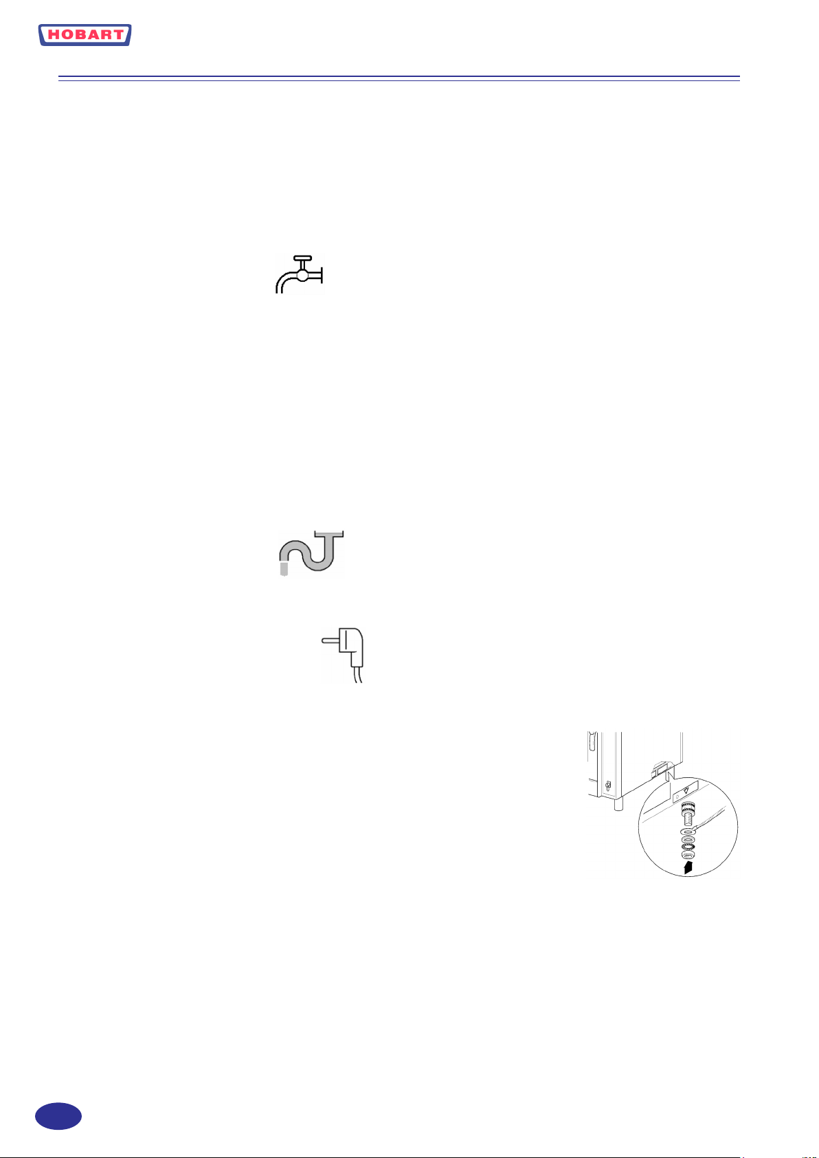
1.1 WATER CONNECTION
Must be cold, potable and softened water (hardness must be below 7 deg. Clark). Inlet water pressure must be within 2 (minimum) and 6 (maximum) bar, or equivalently within 200 and 600 kPascal. Inlet water tubing should allow a minimum flow
of 13 l/mn.
Maximum theoretical water consumption is:
- 6 level GN 1/1: 25 litres / h for steam production and 60 litres per longest cleaning cycle.
- 10 level GN 1/1: 40 litres / h for steam production and 60 litres per longest cleaning cycle.
- 10 level GN 2/1: 55 litres / h for steam production and 80 litres per longest cleaning cycle.
- 20 level GN 1/1: 70 litres / h for steam production and 80 litres per longest cleaning cycle.
- 20 level GN 2/1: 90 litres / h for steam production and 100 litres per longest cleaning cycle
Provide a suitable pressure hose ½”, B.S.P. union nut 3/4”
1.2 DRAIN CONNECTION
Must be open type and drain material must be suitable for water at a temperature up to 100° C.
Drain connection is B.S.P. 1” external thread.
1.3 ELECTRICAL CONNECTION
Should only be made by Hobart service or other authorised service agents and must be in accordance with the installation
requirements and all relevant regulations.
Connected loads are as follow:
- 6 level GN 1/1: 9 kW 3 phases + neutral + Earth
- 10 level GN 1/1: 18 kW 3 phases + neutral + Earth
- 10 level GN 2/1: 24 kW 3 phases + neutral + Earth
- 20 level GN 1/1: 36 kW 3 phases + neutral + Earth
- 20 level GN 2/1: 48 kW 400V/3 PH/N/E or 42kW 230V/3 PH/E
The oven is supplied without a power cable. The specifications of the power supply connection flexible cable must match or
be superior to those of the cable with rubber insulation H07RN-F.
The oven must be included in an equipotential system whose efficiency must be checked according to the standards in force.
The screw marked by ”Equipotential” label is near the terminal block on the base.
If installation is 400V without neutral the oven will have to be modified by a Hobart service.
Remove the right side panel to access entry bush joint and terminal blocks.
1.4 OVEN CAPACITY
Depending on the model, the oven may accommodate a maximum of 6, 10, 20 or 40 levels. Accordingly it may contain a
maximum of 24, 40, 80 or 160 kg of food.
GB
- 4 -
Page 5

ENTRY BUSH
- 5 -
GB
Page 6
2. OPERATION
2.1 GENERAL
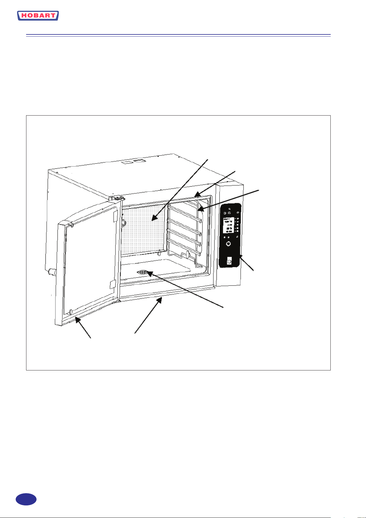
To open the door, rotate the handle to horizontal position: door switch will be deactivated.
To close the door, ensure that the handle is horizontal, shut the door, lock the handle in vertical position: door switch is activated.
PROTECTION GRID
GASKET
SHELVES
CONTROL PANEL
DRAIN FILTER
DRIP TRAYS
The drain filter must always be in place. Lateral shelves are removable for cleaning. The protection grid covering fan and
heating elements must always be in place for safety and air flow distribution. It is removable for cleaning. The drip trays
will receive and evacuate water drops during door openings.
GB
- 6 -
Page 7
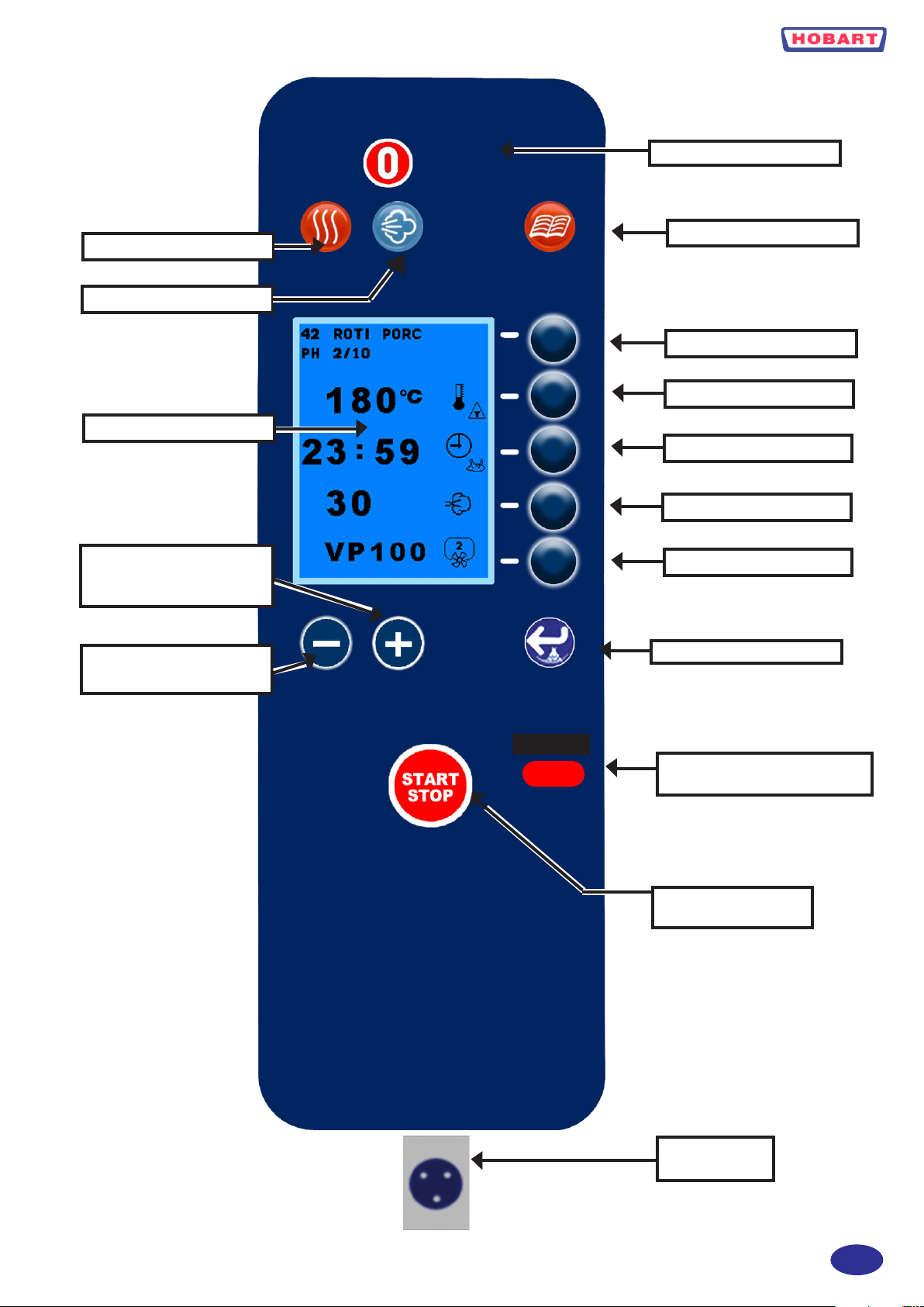
2.2 CONTROL PANEL
ON/OFF SWITCH
CONVECTION : ON/OFF
STEAM : ON/OFF
DISPLAY
PLUS KEY +
SCROLL DOWN
MINUS KEY +
SCROLL UP
PROGRAM
SELECTION LINE 1
SELECTION LINE 2
SELECTION LINE 3
SELECTION LINE 4
SELECTION LINE 5
HUMIDIFYER + ENTER
INFRARED COMMUNICATION
WINDOW
START / STOP
COOKING CYCLES
CORE PROBE
CONNECTOR
- 7 -
GB
Page 8
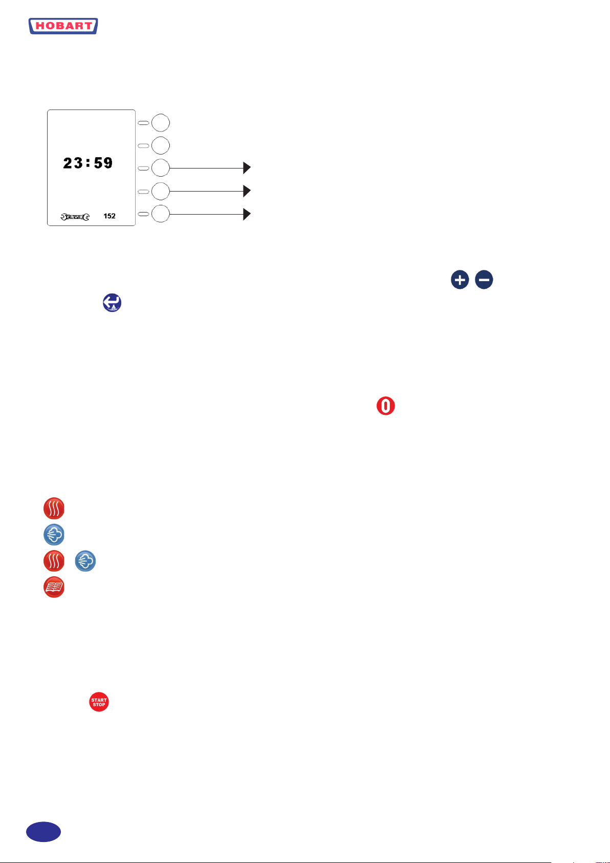
2.2.1 MACHINE CONNECTED TO ELECTRICAL SUPPLY:
When machine is electrically powered, the screen will illuminate and indicate actual time and time left before next descaling
or next service review:
TIME ADJUSTMENT
CHOICE 24h or 12h AM/PM
RESET SERVICE or DELIMING COUNTER
2.2.1.1 TIME AND DATE ADJUSTMENT
To adjust time, press corresponding key (line 3) for 5 seconds, adjust time and date using keys then validate
with enter key .
2.2.1.2 24H OR 12H AM/PM
To switch from 24 h display to 12 h AM/PM display press corresponding key (line 4) until correct time mode is displayed.
2.2.1.3 SERVICE COUNTER
To reset service or descaling counter, press corresponding key (line 5) during 5 seconds. After 15 minutes without any action
on the control panel, the screen will switch off. It can be reactivated by pressing or by opening/closing the door.
2.2.2 START UP
Selecting a cooking mode starts up the oven. To deactivate a cooking mode press again the illuminated key.
2.2.3 COOKING MODE SELECTION
CONVECTION MODE
STEAM MODE
+ COMBINATION MODE
PROGRAM MODE
After selecting one of the 3 cooking modes:
- The default temperature corresponding to the selected cooking mode is displayed during 5 seconds (inverted contrast
symbol) and is then replaced by real measured cavity temperature.
- Cavity lights are on (only if door is closed and locked).
- Selected cooking mode keys are illuminated.
- By default timer is in manual mode.
- The key starts (illuminated) or stops (off) cooking process.
- Selecting program mode will deactivate other selected cooking modes. If door is opened during a cooking process, the
cooking process will stop and restart where it was when door is closed again.
When selecting a cooking mode, the display will show the following screen:
GB
- 8 -
Page 9
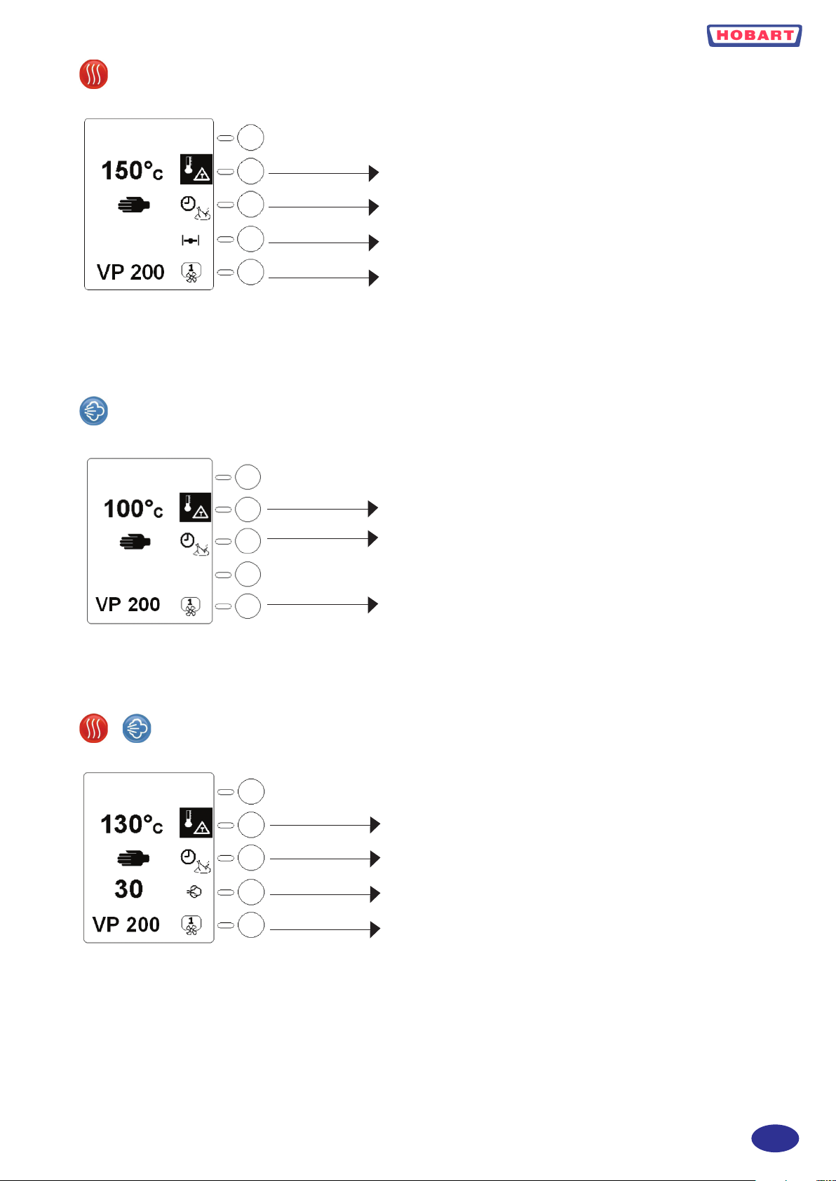
CONVECTION MODE
STEAM MODE
DEFAULT TEMPERATURE DURING 5 Secs.
THEN REAL CAVITY TEMPERATURE
TIMER MANUAL MODE
VENT POSITION
FAN SPEED AND VP (option)
+ COMBINATION MODE
DEFAULT TEMPERATURE DURING 5 Secs.
THEN REAL CAVITY TEMPERATURE
TIMER MANUAL MODE
FAN SPEED AND VP (option)
DEFAULT TEMPERATURE DURING 5 Secs.
THEN REAL CAVITY TEMPERATURE
TIMER MANUAL MODE
HUMIDITY LEVEL
FAN SPEED AND VP (option)
- 9 -
GB
Page 10
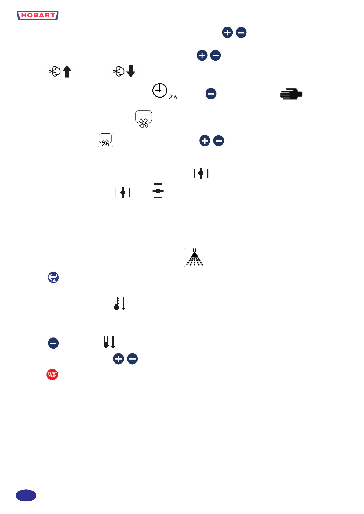
2.2.4 ADJUSTMENT OF TEMPERATURE, TIME OR HUMIDITY .
To adjust one of the above settings, select the line by pressing the corresponding key located on the right side of the screen
(inverted contrast symbol) then adjust desired value with the two keys . In combination mode the display will show
addition or evacuation of humidity. If a cooking time has been set and it is desired to come back to
manual mode (continuous cooking), select the line then press until the manual symbol appears.
2.2.5 FAN SPEED ADJUSTMENT
Select the corresponding line and adjust speed 1 to 4 using keys .
2.2.6 VENT POSITION (CONVECTION MODE ONLY)
Press the corresponding key to open or close .
IT IS NOT NECESSARY TO VALIDATE WITH THE ENTER KEY:
Values are automatically taken into account.
2.2.7 HUMIDIFYER (CONVECTION MODE ONLY)
The key allows injecting water in the cavity during cooking process.
2.2.8 FAST COOL DOWN
Whatever cooking mode has been selected, it is possible to automatically cool down the cavity by water injection in the fan:
1) Press line 3 key (timer)
2) Press until the symbol appears.
3) Adjust desired final temperature .
4) Start
Note: Choosing another mode will stop above process
GB
- 10 -
Page 11
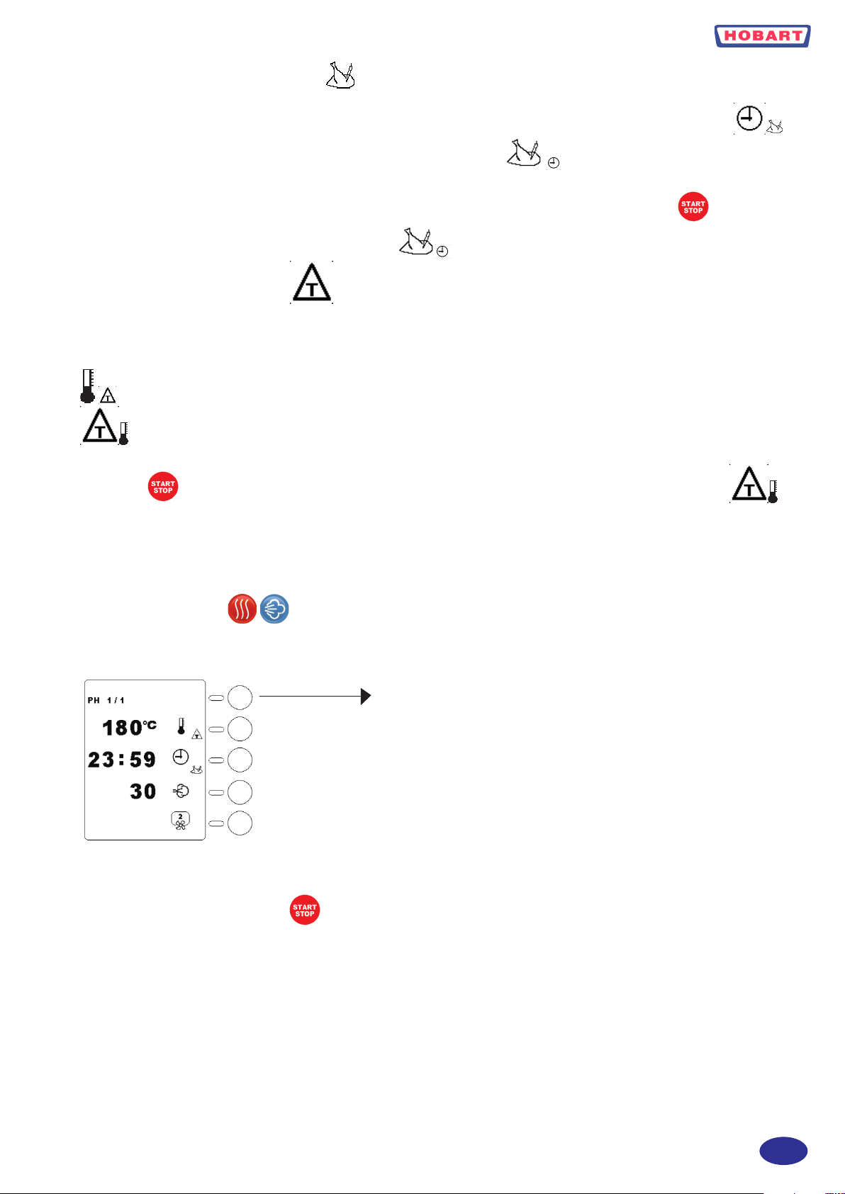
2.2.9 CORE PROBE FUNCTION
Connect core temperature probe into connector located at bottom of control panel. Press during 5 seconds line 3 key
display indicates set core probe temperature and shows following symbol on the right side of the screen. After 5
seconds displayed temperature is real temperature measured by the probe. Adjust desired set temperature as described before.
Place probe into the centre of the food to be controlled, close and lock the door, start cooking process with key. To come
back to timer function, depress for 5 seconds line 3 key .
2.2.10 DELTA T FUNCTION
Cooking with DELTA T automatically controls the cavity cooking temperature, following the product core temperature with
a constant difference. DELTA T can be used with all three cooking modes. Press the corresponding key to line 2 for 5 seconds
the display indicates the default set temperature difference between cavity and core probe for 5 seconds. The symbol
is contrasted on the right of the screen. Core probe function is automatically activated. Adjust set points for DELTA
T and core probe temperatures as described above. Insert core probe into the centre of the food to control, close and lock the
door, press to start cooking process. To cancel DELTA T function, maintain line 2 key pressed for 5 seconds .
2.2.11 COOKING PHASES PH 1/10
It is possible to link up to 10 cooking phases without using the program function.
1) Select a cooking mode .
2) Adjust cooking temperature or DELTA T temperature.
3) Adjust cooking time or core probe temperature.
4) Validate first phase line1 (PH 1/1) the screen goes to next phase (PH 2/2).
PHASE VALIDATION KEY
5) Reiterate for each phase.
6) After the last phase press the phase validation key twice.
7) Start cooking process by pushing
TO ERASE ONE COOKING PHASE
When the phase to be erased is displayed press the phase validation key for 5 seconds then release.
- 11 -
GB
Page 12
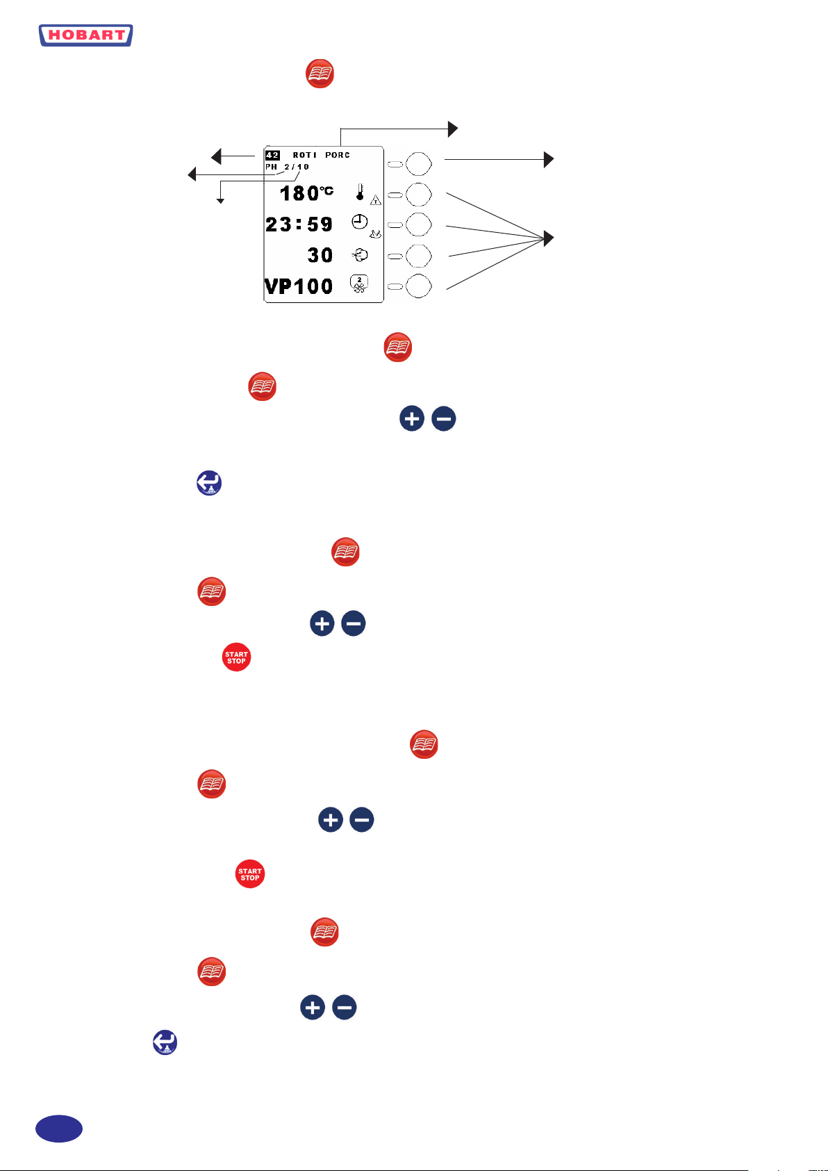
2.2.12 PROGRAMME FUNCTION
It is possible to write and store up to 100 cooking programmes of 10 phases each.
PROGRAMME NAME
PROGRAMME N°
PHASE N°
NUMBER
OF PHASES
2.2.12.1 TO WRITE A COOKING PROGRAMME
1- Press programme key. The key will illuminate.
2- Select programme number under which you want to save: .
3- Write and validate all the phases of the new cooking programme. The programme number will blink to indicate that it has
not been stored yet.
4- Validate programme : Buzzer is activated and programme number will be inverted contrast in order to indicate
saving.
PHASE KEY AND FIRST LINE
SELECTION KEY
KEYS FOR LINE SELECTION OR
SPECIAL FUNCTIONS
2.2.12.2 TO EXECUTE A PROGRAMME
1- Press programme key The key will illuminate.
2- Select programme number that you want: .
3- Start cooking programme The buzzer will be activated at each phase change.
4- The display will show total remaining time until the end of cooking, unless some phases are using core probe temperature.
Pressing one of the line keys will display the corresponding set parameter for the operating phase.
2.2.12.3 TO VISUALISE A COOKING PROGRAMME
1- Press programme key The key will illuminate.
2- Select programme number to be visualised: . The screen will display the first phase of the programme. Press the
phase key (line 1) to visualise and scroll through other phases.
3- To check total time, activate (Except if one of the phases is using core probe).
2.2.12.4 TO ERASE A PROGRAMME
1- Press programme key The key will illuminate.
2- Select programme number to be erased: .
3- Maintain key pressed for 5 seconds.
GB
- 12 -
Page 13
2.2.12.5 TO MODIFY A PROGRAMME
1- Press programme key The key will illuminate.
2- Select programme number to be modified: .
3- Modify desired phases and parameters: The programme number will blink.
4- Validate new programme : The buzzer is activated and the programme number is inverted contrast to indicate sa-
ving.
Notes: You can run a modified programme before validation. In that case, validation can be done after the end of cooking. It
is not possible to insert a phase into a programme.
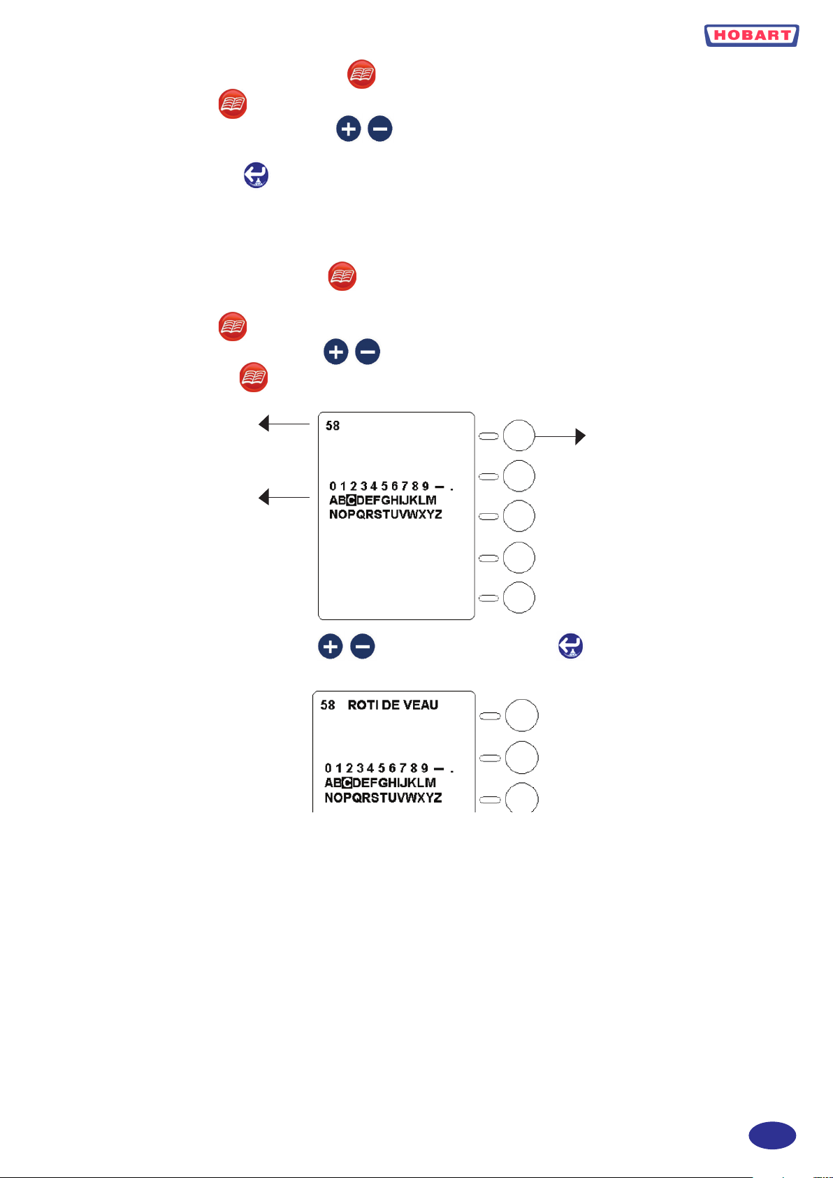
2.2.12.6 TO NAME A PROGRAMME
It is possible to associate a name with a programme number:
1- Press programme key the key will illuminate.
2- Select programme number to be named: .
3- Maintain programme key pressed during 4 seconds. The screen will display the following:
PROGRAMME NUMBER
AVAILABLE CHARACTERS
4- Select letters or numbers with the keys and validate with the enter key Selected characters will locate at
the right of the programme number:
ERASE CHARACTER KEY
- 13 -
GB
Page 14
5- At the end validate the name by pressing for 5 seconds. Programme number stops blinking and buzzer sounds. If you
wish to exit programme press programme key .
2.2.13 PARTICULAR FUNCTIONS
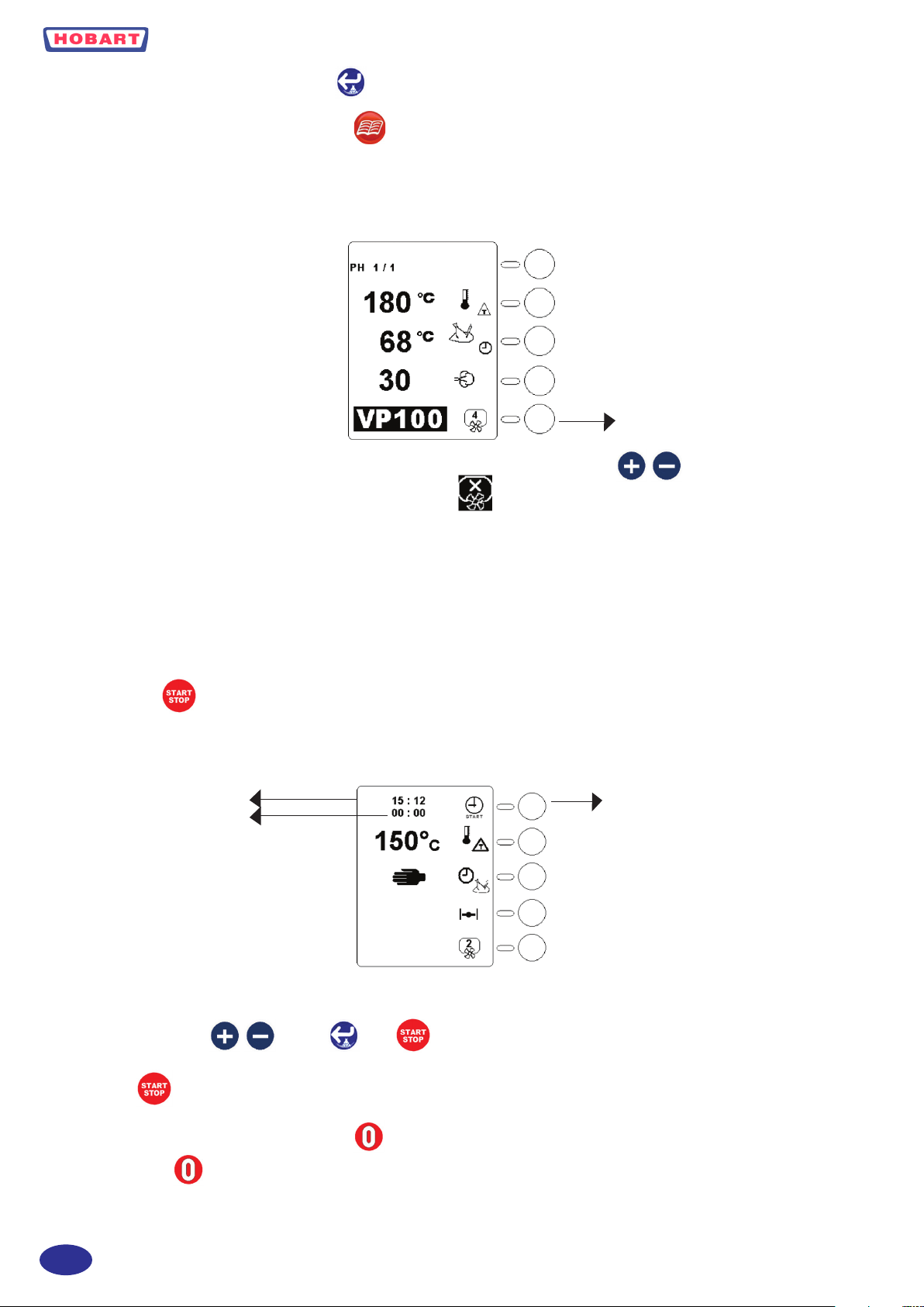
2.2.13.1 VP (PASTEURISATION VALUE) MODE (OPTION)
This function must be selected during initial configuration of the oven. It can only work when core probe is used.
VP KEY FAN SPEED KEY
Press 5 seconds the line 5 key, display of VP will contrast. Adjust desired VP using keys .
One push on line 5 key will change from VP adjustment to fan speed adjustment.
Cooking cycle will only end when set VP and set core probe temperature are reached. To deactivate VP, set VP value at 0.
2.2.13.2 OVEN PREHEATING
When you have selected a cooking mode, adjusted temperature and time or if you are using a programme, it is possible to
automatically preheat the oven at the correct cooking temperature.
In order to do so:
- Write your cooking programme or call an existing programme from the memory
- Press the key during 5 seconds.
2.2.13.3 TO PROGRAM PREHEAT START
It is possible to program the oven in order to start preheating at a given time.
ACTUAL TIME
STARTING TIME
SELECTION KEY
1- Select a cooking mode, adjust desired preheat temperature.
2- Press the selection key.
3- Adjust starting time validate start . It is possible to stop process either by selecting a cooking mode
or pushing .
2.2.14 TO SWITCH OFF THE OVEN
Press the off key the display will be as follow:
GB
- 14 -
Page 15
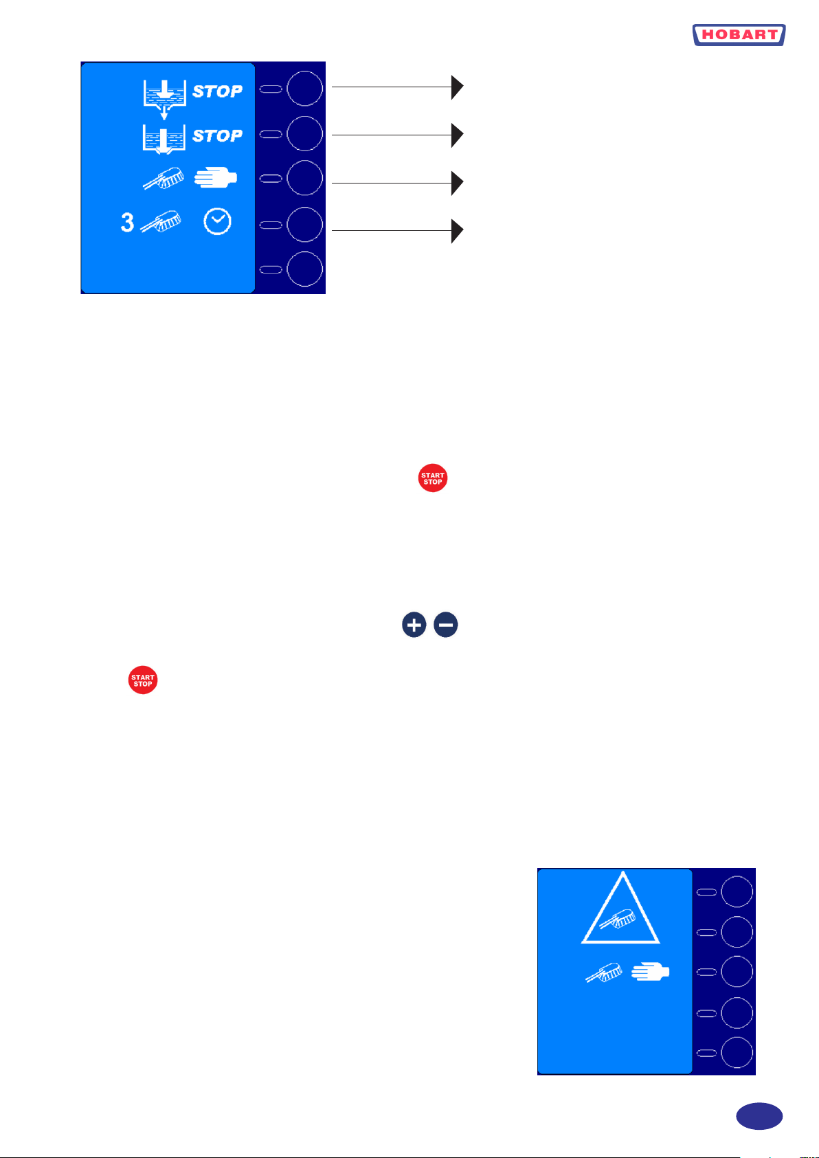
STOP WITH BOILER DRAIN
STOP WITH BOILER FULL
MANUAL CLEAN CYCLE
AUTOMATIC CLEAN CYCLE
STOP WITH BOILER DRAIN
At end of the day if you do not want to carry out a cleaning cycle.
STOP WITH BOILER FULL
For a temporary stop during the day and you plan to use the oven soon there is no need to empty the boiler.
MANUAL CLEAN CYCLE
After pushing the corresponding key, start the cycle with the key. The oven will start in steam mode. A buzzer sound
will advise you to spray the entire cavity with an appropriate detergent, taking all safety measures recommended by the detergent supplier. After closing the door, the cycle will restart and end up with appropriate rinsing of the cavity, followed by a
double boiler drain.
AUTOMATIC CLEAN CYCLE
Before starting an automatic cleaning cycle, verify that you have enough detergent left in the detergent container and that the
pump tube is correctly inserted in the container. Using the keys you can change the amount of detergent (from 0
TO 8) which will be used during the cleaning cycle depending on the degree of dirtiness of your machine. Then start the cycle
with the key. Depending on the status of your machine the cleaning cycle may start with a cool down to bring the ma-
chine at the correct washing temperature.
WARNING:
That screen indicates that the cleaning cycle has not been successfully completed or has been interrupted. There may be
some detergent left in the cavity or in the boiler.
You must thoroughly rinse the cavity of the oven and carry out a double drainage of the boiler (using the STOP WITH
BOILER DRAIN PROGRAM). Or you can select and carry out the MANUAL CLEAN CYCLE.
Do not use the machine without completing one of the above.
IMPORTANT: Always wait complete end of the process before switching of water and electricity.
2.3 DAILY CLEANING AND MAINTENANCE
Remove main pieces of food, which could have fallen in the cavity before starting a cleaning cycle. Perform at least one daily cleaning cycle. Make sure that
the door gasket is clean in order to keep its longevity, wipe it out with a soft wet
cloth after cleaning cycle. Do not use abrasive pads on the glass or stainless steel
surfaces or door gasket, in case of hard to remove stains use an appropriate non
corrosive detergent. Depending on water hardness, you may have to descale the
boiler or the cavity.
To descale the boiler:
- Switch off the oven with boiler drain.
- 15 -
GB
Page 16

- Fill up the boiler with white vinegar or similar descaling product using the steam inlet at the top right hand side of the cavity.
6 level ovens: 5 litres
10 level ovens: 6 litres
20 level ovens: 10 litres
- Select steam mode without starting cycle and wait 30 to 45 minutes depending on the strength of the descaling product.
- Switch off the oven with boiler drain.
- Select steam mode again without starting cycle to rinse the boiler.
- End up with a cleaning cycle.
To descale the cavity:
-Spray on all parts of the cavity a descaling product and let react according to the manufacturer specifications.
-End up with a cleaning cycle.
2.4 AUTODIAGNOSTICS
The microprocessor of your oven constantly checks the proper functioning of the machine, and advises you by a symbol
located on the bottom right of the screen of possible faults on the oven. That symbol appears in place of the fan speed
symbol. Faults are numbered and the corresponding number will be displayed in the screen:
0 Electronic components overheat (CPU)
1 Cavity overheat
2 Boiler overheat
3 Cavity probe fault
4 Vent probe fault
5 Condensates probe fault
6 Boiler probe fault
7 Core probe fault or not connected
8 Fan motor fault
9 Lack of water in the boiler
10 Building energy optimisation system in action
11 Static relays overheat
Notes:
Faults must be corrected otherwise they will be displayed each time a function using the faulty component is selected.
The fault display stays on if the corresponding mode or function cannot be used. Select another mode or function.
The five last faults are memorised and dated.
If a fault occurs during a cooking programme, that programme will stop.
16 If a fault is displayed before starting a programme, it will not be possible to activate that programme.
GB
- 16 -
Page 17

TEMPORARY OPERATION OF THE OVEN IN CASE OF FAULTS
These functions are only here to help you finish your work in case of faulty component. Call your service technician
for repair. Do not use constantly the oven under these functions.
CONVECTION MODE: If the cavity probe is faulty stop the oven and then press the convection key for 10 seconds
. Temperature will be regulated at around 160°C by the core probe, which must be inserted into the cavity and attached
to one of the shelf.
STEAM MODE: If the boiler is faulty, stop the oven . Press steam key for 10 seconds . Steam will be produced by
water injection in the fan at around 100°C. In both of these modes, it is not possible to adjust temperature or select a cooking
time you can only start or stop the cooking cycle by pressing to exit these modes and return to standard modes press
.
- 17 -
GB
Page 18

SOmmAIRE
CHAPITRE DESCRIPTION PAGE
Remarques ...................................................................................................................................... 19
1. Installation .......................................................................................................................................... 20
1.1 Raccordement hydraulique ................................................................................................................. 20
1.2 Raccordement du tuyau de vidange .................................................................................................... 20
1.3 Branchement électrique ...................................................................................................................... 20
1.4 Capacité four ....................................................................................................................................... 20
2. Fonctionnement ................................................................................................................................... 22
2.1 Généralités .......................................................................................................................................... 22
2.2 Panneau de contrôle ............................................................................................................................ 23
2.2.1 Machine branchée a l’alimentation électrique ................................................................................... 24
2.2.1.1 Réglage de l’heure .............................................................................................................................. 24
2.2.1.2 Sélection 24 h ou 12h am/pm .............................................................................................................. 24
2.2.1.3 Compteur d’entretien .......................................................................................................................... 24
2.2.2 Allumage du four ................................................................................................................................. 24
2.2.3 Sélection d’un mode de cuisson .......................................................................................................... 24
2.2.4 Réglage de la température, temps de cuisson ou humidité ................................................................. 26
2.2.5 Réglage de la vitesse de la turbine ...................................................................................................... 26
2.2.6 Position oura (en mode convection seulement) ................................................................................... 26
2.2.7 Humidificateur (en mode convection seulement) ................................................................................ 26
2.2.8 Baisse rapide de la température dans l’enceinte ................................................................................. 26
2.2.9 Fonction sonde à cœur ........................................................................................................................ 27
2.2.10 Fonction Delta T ................................................................................................................................. 27
2.2.11 Phases de cuisson PH 1/10 ................................................................................................................. 27
2.2.12 Fonction programme ........................................................................................................................... 28
2.2.12.1 Enregistrement d’un programme ......................................................................................................... 28
2.2.12.2 Exécution d’un programme ................................................................................................................. 28
2.2.12.3 Affichage d’un programme .................................................................................................................. 28
2.2.12.4 Effacement d’un programme ............................................................................................................... 28
2.2.12.5 Modification d’un programme ............................................................................................................ 29
2.2.12.6 Appellation d’un programme .............................................................................................................. 29
2.2.13 Fonctions particulières ........................................................................................................................ 30
2.2.13.1 Mode VP (valeur de pasteurisation) (option) ..................................................................................... 30
2.2.13.2 Préchauffage du four ........................................................................................................................... 30
2.2.13.3 Programme du préchauffage ............................................................................................................... 30
2.2.14 Arrêt du four ........................................................................................................................................ 31
2.3 Nettoyage quotidien et entretien ......................................................................................................... 32
2.4 Autodiagnostic .................................................................................................................................... 32
Schémas d’installation ........................................................................................................................ 50
F
- 18 -
Page 19

REmARQUES
L’émission sonore de la machine est inférieure à 70 dB (A).
Consignes d’utilisation
- Utiliser le four conformément aux instructions contenues dans ce manuel.
Les fours mixtes à convection et vapeur ne sont adaptés que pour la cuisson, le rôtissage, le gratinage, la cuisson
à la vapeur et à l’étouffée d’aliments destinés à la consommation.
- Sécurité
Il est interdit de nettoyer le four avec un jet d’eau ou un nettoyeur haute pression. Le pictogramme «danger »
veut attirer l’attention du lecteur sur des consignes importantes pour un fonctionnement en toute sûreté du
four. Ces consignes doivent être lues avec beaucoup d’attention.
- Responsabilité
Une erreur d’installation, une réparation non effectuée par le personnel Hobart ou un centre SAV agréé, ainsi
que toute modication non autorisée par le fabricant rend la garantie caduque.
Toutes les méthodes, durées et temps de cuisson reportés dans ce manuel sont donnés à titre d’exemple et
dépendent de la qualité des aliments à cuire.
Le fabricant décline toute responsabilité en cas de dégâts corporels ou matériels provoqués par le non-respect des
instructions reportées dans ce manuel.
LE FABRICANT DECLINE AUSSI TOUTE RESPONSABILITE EN CAS DE DEGATS CORPORELS OU MATERIELS
PROVOQUES PAR UNE ERREUR D’INTERPRETATION OU DES ERREURS D’IMPRESSION DE CE MANUEL. LE
FABRICANT SE RESERVE LE DROIT D’APPORTER TOUTES LES MODIFICATIONS QU’IL JUGERA UTILES, SANS
INFLUER SUR LES CARACTÉRISTIQUES DE BASE DU PRODUIT.
- 19 -
F
Page 20

1. INSTALLATION
Avant de déballer le four, vérifier l’état du colis. En présence de dégâts apparents, veuillez adresser les réclamations d’usage
au transporteur.
OUVERTURE DROITE / GAUCHE DE LA PORTE : Le four est généralement livré avec la porte s’ouvrant par la gauche.
Les clients qui souhaitent une ouverture à droite de la porte doivent le préciser au moment de la commande.
Le four doit être installé et branché conformément à la législation locale en la matière.
Le four doit être installé sur un support ou un plancher de niveau. Vérifier la mise à niveau du four avec un niveau à bulle, en
prenant le sommet du four comme point de repère.
1.1 RACCORDEMENT HYDRAULIQUE
Le four doit être raccordé à un réseau d’eau froide, potable et adoucie (la dureté doit être inférieure à 7° français). Le réseau
d’eau doit avoir une pression entre 2 (minimum) and 6 (maximum) bars, ou également entre 200 et 600 kPascal. Le réseau
d’eau doit ainsi garantir un débit minimum de 13 l/mn.
La consommation d’eau maximale théorique est de :
- GN 1/1 à 6 niveaux : 25 l/h pour la production de vapeur et 60 litres pour le cycle de nettoyage le plus long.
- GN 1/1 à 10 niveaux : 40 l/h pour la production de vapeur et 60 litres pour le cycle de nettoyage le plus long.
- GN 1/1 à 10 niveaux : 55 l/h pour la production de vapeur et 80 litres pour le cycle de nettoyage le plus long.
- GN 1/1 à 20 niveaux : 70 l/h pour la production de vapeur et 80 litres pour le cycle de nettoyage le plus long.
- GN 1/1 à 20 niveaux : 90 l/h pour la production de vapeur et 100 litres pour le cycle de nettoyage le plus long.
Prévoir un flexible rèsistant à la pression, de diamètre intérieur d’1/2”, d’une longueur adéquate et muni de raccords femelles
de jonction B.S.P. 3/4”.
1.2 RACCORDEMENT DU TUYAU DE VIDANGE
Le raccordement doit être de type ouvert et sa composition doit être adaptée à de l’eau pouvant atteindre une température
jusqu’à 100°C. Le raccord du tuyau de vidange est B.S.P. 1” màle.
1.3 BRANCHEMENT ÉLECTRIQUE
Le branchement électrique doit être effectué par le personnel du fabricant ou par d’autres électriciens agréés, et doit être
conforme à toutes les exigences d’installation et à toutes les normes en vigueur en matière.
Les puissances installèes sont les suivantes :
- GN 1/1 à 6 niveaux : 9 kW 3 phases + neutre + Terre
- GN 1/1 à 10 niveaux : 18 kW 3 phases + neutre + Terre
- GN 2/1 à 10 niveaux : 24 kW 3 phases + neutre + Terre
- GN 1/1 à 20 niveaux : 36 kW 3 phases + neutre + Terre
- GN 2/1 à 20 niveaux : 48 kW 400V/3 PH/N/T ou 42kW 230V/3 PH/T
L’appareil est livré sans câble d’alimentation. Le flexible pour le branchement à la ligne électrique doit être conforme au
flexible modèle H07RN-F.
L’appareil doit être inclus dans un système équipotentiel dont le fonctionnement doit être vérifié conformément à la
réglementation en vigueur. La vis marquée avec l’étiquette “Equipotentiel” se trouve à côté du bornier sur la base.
Si l’installation est en 400V et n’a pas de neutre, le four doit être modifié par le personnel du fabricant Hobart. Démonter le
panneau de droite pour accéder au presse étoupe d’entrée et au bornier.
1.4 CAPACITÉ FOUR
Selon le model, le four peut loger 6, 10, 20 ou 40 niveaux. En conséquence il peut contenir un maximum de 24, 40, 80 ou
160 kg de nourriture.
F
- 20 -
Page 21

PRESSE ÉTOUPE
- 21 -
F
Page 22

2. FONCTIONNEmENT
2.1 GÉNÉRALITÉS
Pour ouvrir la porte, tourner la poignée à l’horizontale, ce qui provoquera le déverrouillage de la porte.
Pour refermer la porte, vérifier si la poignée est à l’horizontale, refermer la porte et bloquer la poignée en position verticale,
ce qui provoquera le verrouillage de la porte.
GRILLE DE PROTECTION
JOINT
GLISSIÉRES
PANNEAU DE CONTRÔLE
FILTRE DE VIDANGE
ÉGOUTTOIR PORTE
Le filtre de vidange doit toujours être installé dans sa position. Les glissières latérales sont amovibles pour faciliter leur nettoyage. La grille de protection, qui couvre la turbine et les résistances, doit toujours être installée dans sa position pour des
raisons de sécurité et pour une distribution homogène du flux d’air. Elle peut être démontée pour son nettoyage. L’égouttoir
de la porte recueille et élimine les gouttes d’eau lorsque la porte est fermée, tandis que l’égouttoir du four recueille et élimine
les gouttes dans toutes les situations.
F
- 22 -
Page 23

2.2 PANNEAU DE CONTRÔLE
TOUCHE ARRET
CONVECTION :M / A
VAPEUR : M / A
AFFICHEUR
TOUCHE +
DÉROULEMENT VERS LE
BAS DE L’ÉCRAN
TOUCHE -
DÉROULEMENT VERS LE
HAUT
PROGRAMME
LIGNE DE SÉLECTION 1
LIGNE DE SÉLECTION 2
LIGNE DE SÉLECTION 3
LIGNE DE SÉLECTION 4
LIGNE DE SÉLECTION 5
HUMIDIFICATEUR OU
VALIDATION
FENÊTRE DE COMMUNICATION
A INFRAROUGES
MARCHE / ARRÊT
CYCLES
DE CUISSON
CONNECTEUR
SONDE À CŒUR
- 23 -
F
Page 24

2.2.1 MACHINE BRANCHÉE A L’ALIMENTATION ÉLECTRIQUE :
Une fois que la machine est alimentée, l’écran s’allume et affiche l’heure et le temps qui doit s’écouler avant le prochain
détartrage ou la prochaine révision :
RÉGLAGE DE L’HEURE
SÉLECTION 24 h OU 12h AM/PM
REINITIALISATION COMPTEUR DE DETARTRAGE OU
D’ENTRETIEN
2.2.1.1 RÉGLAGE DATE ET HEURE
Pour régler l’heure, appuyer sur la touche correspondante (ligne 3) pendant 5 secondes, régler l’heure et la date avec les
touches, puis confirmer avec la touche Enter .
2.2.1.2 24H OU 12H AM/PM
Pour passer de l’affichage à 24 h à celui de 12 h AM/PM, appuyer sur la touche correspondante (ligne 4) jusqu’à ce que la
modalité sélectionnée s’affiche.
2.2.1.3 COMPTEUR D’ENTRETIEN
Pour effacer le compteur d’entretien ou de détartrage, appuyer sur la touche correspondante (ligne 5) pendant 5 secondes. Si
aucune fonction n’est activée pendant 15 minutes, l’écran du panneau de contrôle s’éteint. Pour le rallumer, il suffit d’ouvrir
ou de fermer la porte ou d’appuyer sur .
2.2.2 MISE EN ROUTE DU FOUR
Sélectionner un mode de cuisson, pour desactiver le mode sélectionné appuyer de nouveau sur la touche.
2.2.3 SÉLECTION DU MODE DE CUISSON
MODE CONVECTION
MODE VAPEUR
+ MODE MIXTE
MODE PROGRAMME
Après avoir sélectionné un des 3 modes de cuisson :
- La température préétablie correspondant au mode de cuisson sélectionné s’affiche pendant 5 secondes, remplacée
ensuite par la température réelle de l’enceinte.
- L’enceinte de cuisson est éclairée (mais seulement si la porte est fermée et verrouillée).
- Les touches des modes de cuisson sélectionnés s’allument.
- Implicitement la minuterie est en mode manuel.
- La touche met en marche (allumée) ou arrête (éteinte) le processus de cuisson.
- La sélection du mode programme désactive les autres modes de cuisson sélectionnés. En cas d’ouverture de la porte pendant
la cuisson, le four s’arrête immédiatement pour reprendre du point où il s’était arrêté dès que la porte a été refermée.
F
- 24 -
Page 25

Après avoir sélectionné un mode de cuisson, l’écran affiche les données suivantes :
MODE CONVECTION
TEMPÉRATURE DE CONSIGNE PENDANT 5 sec.
PUIS TEMPÉRATURE RÉELLE DE L’ENCEINTE
MODE MANUEL / MINUTERIE / SONDE A COEUR
POSITION DE L’OURA
VITESSE TURBINE / VALEUR PASTEURISATRICE (option)
MODE VAPEUR
+ MODE MIXTE
TEMPÉRATURE DE CONSIGNE PENDANT 5 sec.
PUIS TEMPÉRATURE RÉELLE DE L’ENCEINTE
MODE MANUEL / MINUTERIE / SONDE A COEUR
VITESSE TURBINE / VALEUR PASTEURISATRICE (option)
TEMPÉRATURE DE CONSIGNE PENDANT 5 sec.
PUIS TEMPÉRATURE RÉELLE DE L’ENCEINTE
MODE MANUEL / MINUTERIE / SONDE A COEUR
NIVEAU HUMIDITÉ
VITESSE TURBINE / VALEUR PASTEURISATRICE (option)
- 25 -
F
Page 26

2.2.4 RÉGLAGE DE LA TEMPÉRATURE, TEMPS DE CUISSON OU HUMIDITÉ .
Pour régler une des fonctions ci-dessus, sélectionner la ligne en appuyant sur la touche correspondante sur le côté droit
de l’écran (symbole en négatif), puis entrer la valeur souhaitée avec les deux touches . En mode mixte, l’écran
affichera adjonction ou élimination d’humidité. Si un temps de cuisson a été programmé et l’on
souhaite revenir au mode manuel (cuisson continue), selectionner la ligne et appuyer sur jusqu’à ce que
le symbole manuel s’affiche.
2.2.5 RÉGLAGE DE LA VITESSE DE LA TURBINE
Sélectionner la ligne correspondante et régler la vitesse de 1 à 4 avec les touches .
2.2.6 POSITION DE L’OURA (EN MODE CONVECTION SEULEMENT)
Appuyer sur la touche correspondante pour ouvrir ou fermer .
IL N’EST PAS NÉCESSAIRE DE CONFIRMER AVEC LA TOUCHE VALIDATION
car les paramètres sont mis au point automatiquement.
2.2.7 HUMIDIFICATEUR (EN MODE CONVECTION SEULEMENT)
La touche permet d’introduire de l’eau dans l’enceinte pendant la cuisson.
2.2.8 REFROIDISSEMENT RAPIDE DE LA TEMPÉRATURE DANS L’ENCEINTE
Quel que soit le mode de cuisson sélectionné, il est possible de refroidir rapidement l’enceinte de cuisson en injectant de l’eau
froide et à une pression préétablie dans la turbine :
1) Appuyer sur la touche de la ligne 3 (minuterie) en manuel.
2) Appuyer sur jusqu’à ce que le symbole s’affiche.
3) Régler la température finale souhaitée .
4) Mettre en route .
Note : la sélection d’un autre mode arrêtera le processus sélectionné au-dessus.
F
- 26 -
Page 27

2.2.9 FONCTION SONDE À CŒUR
Brancher la sonde de température à cœur au connecteur situé au bas du panneau de contrôle. Appuyer pendant 5 secondes sur
la touche de la ligne 3. l’écran affiche la température de la sonde à cœur programmée ainsi que le symbole suivant
à la droite de l’écran. Après 5 secondes, l’écran affiche la température actuelle de la sonde. Régler la température souhaitée
comme décrit plus haut. Enfoncer la sonde au milieu de l’aliment à contrôler, fermer et verrouiller la porte et mettre en
route le processus de cuisson avec la touche . Pour revenir à la fonction minuterie, appuyer pendant 5 secondes sur
la touche de la ligne 3.
2.2.10 FONCTION DELTA T
La fonction DELTA T contrôle automatiquement la température de l’enceinte en suivant la température au cœur de l’aliment
et en l’ajustant constamment. La fonction DELTA T peut être utilisée avec les trois modes. Appuyer pendant 5 secondes sur
la touche de la ligne 2. l’écran affiche la différence de température préétablie programmée entre l’enceinte et la sonde
à cœur pendant 5 secondes. Le symbole s’affiche à la droite de l’écran. La fonction sonde à cœur s’active automatiquement. Entrer les paramètres de la températures DELTA T et sonde à cœur comme décrit ci-dessus. Enfoncer la sonde au
milieu de l’aliment à contrôler, fermer la porte, appuyer sur pour mettre en route la cuisson. Pour annuler la fonction
DELTA T, appuyer sur la touche de la ligne 2 pendant 5 secondes. .
2.2.11 PHASES DE CUISSON PH 1/10
Il est possible de mettre au point jusqu’à 10 phases de cuisson.
1) Sélectionner un mode de cuisson. .
2) Régler la température de cuisson ou la température DELTA T.
3) Régler le temps de cuisson ou sélectionner la fonction sonde à cœur.
4) Confirmer la première phase sur la ligne 1 (PH 1/1) ; l’écran passe à la deuxième phase (PH 2/2).
TOUCHE CONFIRMATION PHASE
5) Répéter les mêmes opérations pour chaque phase.
6) Après la dernière phase, appuyer deux fois sur la touche de confirmation de phase.
7) Mettre en route la cuisson en appuyant sur
POUR EFFACER UNE PHASE DE CUISSON
Lorsque la phase à effacer est affichée, appuyer sur la touche de confirmation de la phase pendant 5 secondes, puis relâcher.
Un signal sonore confirme l’effacement.
- 27 -
F
Page 28

2.2.12 FONCTION PROGRAMME
Il est possible d’entrer et de stocker jusqu’à 100 programmes de cuisson de 10 phases chacun.
NOM DU PROGRAMME
N° PROGRAMME
N° PHASE
TOUCHE PHASE ET TOUCHE DE
SÉLECTION PREMIÈRE LIGNE
NOMBRE DE
PHASES
SÉLECTION LIGNES OU FONCTIONS
2.2.12.1 ENREGISTREMENT D’UN PROGRAMME DE CUISSON
1- Appuyer sur la touche programme. La touche s’illumine.
2- Sélectionner le numéro de programme sous lequel on souhaite enregistrer. .
3- Entrer et confirmer toutes les phases du nouveau programme de cuisson. Le numéro du programme clignotera pour indiquer
qu’il n’a pas encore été enregistré.
4- Confirmer le programme : Le buzzer sonnera et le numéro du programme s’affichera en négatif pour indiquer qu’il
a été enregistré.
2.2.12.2 EXÉCUTION D’UN PROGRAMME
1- Appuyer sur la touche programme. La touche s’illumine.
TOUCHES DE
SPÉCIALES
2- Sélectionner le numéro de programme souhaité: .
3- L’écran affichera le temps qui reste jusqu’à la fin de la cuisson, à moins que certaines phases ne prévoient l’utilisation de
la température de la sonde à cœur. La pression d’une des touches de ligne affichera le paramètre correspondant qui a été
mis en consigne pour la phase en cours.
2.2.12.3 POUR AFFICHER UN PROGRAMME DE CUISSON
1- Appuyer sur la touche programme. La touche s’illumine.
2- Sélectionner le numéro de programme à afficher. . L’écran affichera la première phase du programme. Appuyer
sur la touche de phase (ligne 1) pour afficher et dérouler les autres phases.
3- Pour vérifier le temps total, activer (Sauf si une des phases utilise la sonde à cœur).
2.2.12.4 E FFACEMENT D’UN PROGRAMME
1- Appuyer sur la touche programme. la touche s’illumine.
2- Sélectionner le numéro du programme à effacer. .
F
- 28 -
Page 29

3- Appuyer sur la touche pendant 5 secondes.
2.2.12.5 MODIFICATION D’UN PROGRAMME
1- Appuyer sur la touche programme. La touche s’illumine.
2- Sélectionner le numéro de programme à modifier. .
3- Modifier les phases et les paramètres souhaités : le numéro du programme se met à clignoter.
4- Confirmer le nouveau programme : Le buzzer sonnera et le numéro du programme s’affichera en négatif pour indiquer
qu’il a été enregistré.
Note : il est possible d’exécuter un programme modifié avant sa confirmation. Dans ce cas, la confirmation peut être effectuée
à la fin de la cuisson. Il n’est pas possible d’insérer une phase dans un programme.
2.2.12.6 APPELLATION D’UN PROGRAMME
Il est possible d’associer un nom à un numéro de programme.
1- Appuyer sur la touche programme. La touche s’illumine.
2- Sélectionner le numéro de programme à baptiser. .
3- Appuyer sur la touche programme pendant 4 secondes. L’écran affichera les données suivantes:
NUMÉRO DE PROGRAMME
CARACTÈRES DISPONIBLES
4- Sélectionner les lettres ou les chiffres avec les touches et confirmer avec la touche Enter Les caractères
sélectionnés se placeront à droite du numéro de programme :
TOUCHE EFFACEMENT
CARACTÈRE
- 29 -
F
Page 30

5- A la fin, confirmer le nom en appuyant sur la touche pendant 5 secondes. Le numéro du programme arrête de clignoter
le buzzer se met à sonner. Pour sortir du programme, appuyer sur la touche programme .
2.2.13 FONCTIONS PARTICULIÈRES
2.2.13.1 MODE VP (VALEUR DE PASTEURISATION) (OPTION)
Cette fonction doit être sélectionnée pendant la configuration initiale du four. Elle ne peut fonctionner que si on utilise la
sonde à cœur.
TOUCHE VP TOUCHE
VITESSE TURBINE
Appuyer pendant 5 secondes sur la touche de la ligne 5, l’écran VP s’affichera. Entrer la valeur VP avec les touches
. En appuyant une fois sur la touche de la ligne 5, le réglage commutera de la VP à la vitesse de la turbine. Le cycle de
cuisson se terminera seulement lorsque la valeur VP et la température de la sonde à cœur programmées auront été atteintes.
Pour désactiver la fonction VP, la programmer à 0.
2.2.13.2 PRÉCHAUFFAGE DU FOUR
Après avoir sélectionné un mode de cuisson, régler la température et le temps. L’utilisation d’un programme permet de préchauffer automatiquement le four à la juste température.
Pour ce faire :
- Créer son propre programme de cuisson ou entrer les coordonnées d’un programme stocké en mémoire.
- Appuyer sur la touche pendant 5 secondes.
2.2.13.3 PROGRAMMATION DU PRÉCHAUFFAGE
Il est possible de programmer le four de façon à faire partir le préchauffage à une heure donnée
HEURE DE MISE EN ROUTE
HEURE ACTUELLE
1- Sélectionner un mode de cuisson et saisir la température de préchauffage souhaitée.
SÉLECTION
HEURE DE DÉPART
2- Appuyer sur la touche de sélection, heure de départ.
3- Entrer l’heure de mise en route, confirmer mettre en route . Le processus peut être stoppé en sélec-
tionnant un mode de cuisson ou en appuyant sur .
F
- 30 -
Page 31

2.2.14 ARRÊT DU FOUR
Appuyer sur la touche OFF l’écran affiche les données suivantes :
ARRÊT AVEC VIDANGE DE LA CHAUDIÈRE
ARRÊT AVEC CHAUDIÈRE PLEINE
CYCLE DE NETTOYAGE MANUEL
CYCLE DE NETTOYAGE AUTOMATIQUE
ARRÊT AVEC VIDANGE DE LA CHAUDIERE
En fin de journée, si on ne souhaite pas effectuer un cycle de nettoyage automatique, il est possible d’arrêter le processus en
appuyant sur cependant, étant donné que la vidange de la chaudière ne peut pas être interrompue, il faudra attendre 5
minutes avant de remettre le four en route.
ARRÊT AVEC CHAUDIERE PLEINE
Pour un arrêt temporaire pendant la journée.
CYCLE DE NETTOYAGE MANUEL
Après avoir appuyé sur la touche correspondante, démarrer le cycle avec la touche . Le four repart en mode vapeur. Un
signal sonore signalera de nettoyer l’enceinte de cuisson en pulvérisant un nettoyant adapté et en adoptant toutes les mesures
de sécurité préconisées par le fabricant. Après avoir fermé la porte, le cycle redémarrera et se terminera par le rinçage de
l’enceinte suivi par une double vidange de la chaudière.
CYCLE DE NETTOYAGE AUTOMATIQUE
Avant d’entamer un cycle de nettoyage automatique, vérifier s’il y a assez de nettoyant dans le réservoir et si le tuyau de la
pompe est introduit correctement dans le réservoir. Les touches permettent de modifier le nombre de cycles de
détergent à choisir en fonction du degré de saleté du four. Mettre ensuite le cycle en route avec la touch . En fonction
de l’état de la machine, le cycle de nettoyage pourrait commencer par un refroidissement afin d’amener la machine à la juste
température de nettoyage (inférieure à 60°C).
ATTENTION !
Cet affichage signale que le cycle de nettoyage n’a pas abouti ou qu’il a été
interrompu. Probablement il y a encore du nettoyant dans l’enceinte de cuisson ou dans la chaudiere. L’enceinte de cuisson doit être rincée à fond et le
chaudiere vidangé deux fois (avec le programme ARRÊT AVEC VIDANGE
DE LA CHAUDIERE). Il est aussi possible de sélectionner et d’effectuer
un CYCLE DE NETTOYAGE MANUEL. Ne pas utiliser le four sans avoir
d’abord complété les opérations précédentes.
IMPORTANT! attendre toujours la fin totale du cycle avant de désactiver
l’eau et l’électricité.
- 31 -
F
Page 32

2.3 NETTOYAGE QUOTIDIEN ET ENTRETIEN
Avant d’entamer un cycle de nettoyage, enlever les morceaux d’aliments qui auraient pu tomber dans l’enceinte. Effectuer
au moins un cycle de nettoyage par jour. Vérifier la propreté du joint de la porte. Afin d’en prolonger la durée, le sécher avec
un chiffon doux après le cycle de nettoyage. Ne pas utiliser de paille en fer, ni d’autres produits abrasifs pour nettoyer les
surfaces en verre et en acier inoxydable ou le joint de la porte. En cas de difficultés à éliminer les taches, utiliser un nettoyant
non corrosif adéquat. En fonction de la dureté de l’eau, il pourrait s’avérer nécessaire de détartrer la chaudère ou l’enceinte
de cuisson.
Pour détartrer la chaudière, procéder de la façon suivante :
- éteindre le four et vidanger la chaudière,
- remplir la chaudière avec du vinaigre blanc ou du détartrant à travers l’orifice d’entrée de la vapeur situé en haut de l’enceinte à droite, en respectant les quantités suivantes :
fours à 6 niveaux : 5 litres
fours à 10 niveaux : 6 litres
fours à 20 niveaux : 10 litres
- sélectionner le mode vapeur sans mettre en route le cycle et laisser agir de 30 à 45 minutes en fonction de l’efficacité du
détartrant,
- éteindre le four et vidanger la chaudière,
- sélectionner à nouveau le mode vapeur sans mettre en route le cycle pour le rinçage de la chaudière,
- terminer par un cycle de nettoyage. Pour détartrer l’enceinte de cuisson, procéder de la façon suivante:
- pulvériser du détartrant sur toutes les cloisons de l’enceinte de cuisson et laisser agir selon le mode d’emploi du fabricant,
- terminer par un cycle de nettoyage.
2.4 AUTODIAGNOSTIC
Le microprocesseur du four vérifie constamment le bon fonctionnement de la machine et signale les pannes par un symbole
situé en bas à droite de l’écran. Ce symbole s’affiche à la place du symbole de la vitesse de la turbine. A chaque panne correspond un numéro qui s’affiche sur l’écran, à savoir :
0 Surchauffe des composants électroniques (CPU)
1 Surchauffe de l’enceinte de cuisson
2 Surchauffe de la chaudière
3 Défaut sonde de l’enceinte de cuisson
4 Défaut sonde d’oura
5 Défaut sonde des condensats
6 Défaut sonde chaudière
7 Sonde à cœur défectueuse ou pas branchée
8 Défaut moteur de la turbine
9 Absence d’eau dans la chaudière
10 Système d’optimisation de l’énergie de l’édifice en action
11 Surchauffe des relais statiques
12 Défaut sonde à la masse
Remarques :
- Les pannes doivent être éliminées, sinon elles continueront à s’afficher chaque fois que l’on sélectionne une fonction qui
utilise le composant défectueux.
- L’afficheur des pannes reste activé si le mode ou la fonction correspondante ne peut pas être utilisée. Sélectionner un autre
mode ou une autre fonction.
- Les cinq dernières pannes sont enregistrées avec la date.
- Si une panne se produit pendant l’exécution d’un programme de cuisson, ledit programme s’arrête.
- Si une panne s’affiche avant la mise en route d’un programme, la mise en route dudit programme sera impossible.
F
- 32 -
Page 33

FONCTIONNEMENT TEMPORAIRE DU FOUR EN CAS DE PANNE
Ces fonctions ont été étudiées seulement pour mener à terme le cycle en cas de panne. Appeler le centre SAV agréé pour
la réparation. Ne pas utiliser le four dans ces conditions.
MODE CONVECTION: En cas de panne de la sonde de l’enceinte de cuisson, arrêter le four . Appuyer sur la touche
convection pendant 10 secondes . La sonde à cœur règle la température autour de 165°C.
MODE VAPEUR: Si la chaudière est en panne, arrêter le four . Appuyer sur la touche vapeur pendant 10 secondes
. Dans ces deux modes, il n’est pas possible de régler la température ou de sélectionner un temps de cuisson. On ne peut que
mettre en route ou arrêter le cycle de cuisson. De la vapeur sera produite par introduction d’eau dans la turbine à 100°C environ. Pour quitter ces modes et revenir au mode standard, appuyer sur .
- 33 -
F
Page 34

INDICE
SEZIONE DESCRIZIONE PAGINA
Note generali ....................................................................................................................................... 35
1. Installazione ........................................................................................................................................ 36
1.1 Collegamento idraulico ....................................................................................................................... 36
1.2 Collegamento dello scarico ................................................................................................................ 36
1.3 Collegamento elettrico ........................................................................................................................ 36
1.4 Capienza forno ..................................................................................................................................... 36
2. Funzionamento .................................................................................................................................... 38
2.1 Generale .............................................................................................................................................. 38
2.2 Pannello di controllo ........................................................................................................................... 39
2.2.1 Macchina collegata all’alimentazione elettrica .................................................................................. 40
2.2.1.1 Regolazione dell’ora ........................................................................................................................... 40
2.2.1.2 24h o 12h am/pm ................................................................................................................................. 40
2.2.1.3 Contatore di assistenza ....................................................................................................................... 40
2.2.2 Avvio .................................................................................................................................................... 40
2.2.3 Selezione della modalità di cottura ..................................................................................................... 40
2.2.4 Regolazione di temperatura, tempo di cottura o umidità .................................................................... 42
2.2.5 Regolazione della velocità della ventola ............................................................................................ 42
2.2.6 Posizione ventilazione (solo modalità termoconvezione) ................................................................... 42
2.2.7 Umidificatore (solo modalità termoconvezione) ................................................................................. 42
2.2.8 Abbattimento rapido temperatura in camera ...................................................................................... 42
2.2.9 Funzione sonda al cuore ..................................................................................................................... 43
2.2.10 Funzione Delta T ................................................................................................................................. 43
2.2.11 Fasi di cottura PH 1/10 ....................................................................................................................... 43
2.2.12 Funzione programma .......................................................................................................................... 44
2.2.12.1 Inserimento di un programma ............................................................................................................. 44
2.2.12.2 Esecuzione di un programma .............................................................................................................. 44
2.2.12.3 Per visualizzare un programma .......................................................................................................... 44
2.2.12.4 Per cancellare un programma ............................................................................................................. 44
2.2.12.5 Per modificare un programma ............................................................................................................ 45
2.2.12.6 Per denominare un programma .......................................................................................................... 45
2.2.13 Funzioni particolari ............................................................................................................................ 46
2.2.13.1 Modalità VP (valore di pastorizzazione) (opzionale) ......................................................................... 46
2.2.13.2 Preriscaldamento del forno ................................................................................................................ 46
2.2.13.3 Programmare l’avvio del preriscaldamento ....................................................................................... 46
2.2.14 Spegnimento del forno ........................................................................................................................ 47
2.3 Pulizia giornaliera e manutenzione .................................................................................................... 48
2.4 Autodiagnosi ....................................................................................................................................... 48
Schemi di installazione ....................................................................................................................... 50
I
- 34 -
Page 35

NOTE GENERALI
Il livello di rumorosità della macchina è inferiore a 70 dB (A)
Importanti istruzioni per l’uso
- Utilizzare in conformità con le disposizioni
I forni misti a termoconvezione e vapore devono essere utilizzati solo per la cottura, arrostitura, gratinatura,
cottura a vapore e cottura in umido di prodotti alimentari destinati al consumo.
- Sicurezza
Non lavare dall’esterno con una canna o un pulitore ad alta pressione. Il simbolo di “pericolo” compare accanto
alle istruzioni essenziali per il funzionamento sicuro della macchina. Si prega di leggere questi passaggi con
estrema attenzione.
- Responsabilità
L’errata installazione, le riparazioni non effettuate da tecnici Hobart o da un centro assistenza autorizzato e
qualunque modica tecnica non autorizzata dai produttori potrebbero comportare il decadimento della garanzia
del produttore.
Tutti gli esempi forniti in queste istruzioni con riferimento a metodi, tempi e temperature di cottura dipendono
dalla qualità degli alimenti da cuocere e pertanto possono variare.
Nel caso in cui l’utente o l’installatore non rispettino le istruzioni fornite in questo manuale, la casa declina tutte le
responsabilità da ciò derivanti e non potrà essere ritenuta responsabile per qualsivoglia incidente o problema causato
da tale inosservanza.
IL PRODUTTORE DECLINA QUALUNQUE RESPONSABILITÀ PER QUALSIVOGLIA IMPRECISIONE CONTENUTA IN QUESTO DOCUMENTO CHE POSSA ESSERE DOVUTA A ERRORI DATTILOGRAFICI O TIPOGRAFICI. IL
PRODUTTORE SI RISERVA INOLTRE IL DIRITTO DI APPORTARE AL PRODOTTO LE MODIFICHE CHE RITENGA
UTILI O NECESSARIE, SENZA INFLUIRE SULLE CARATTERISTICHE DI BASE
- 35 -
I
Page 36

1. INSTALLAZIONE
Prima di togliere l’imballaggio, verificare le buone condizioni della scatola; in caso di danni, si prega di presentare le necessarie rimostranze alla società di trasporto.
LATO DI APERTURA SPORTELLO: Normalmente il forno viene consegnato con le cerniere della porta sulla sinistra. Se
si desiderano sul lato destro, si prega di specificare tale preferenza al momento dell’ordine.
Il forno dev’essere installato e collegato in conformità con normative locali.
Il forno dev’essere installato su un supporto o pavimento adeguatamente livellato. Verificare il livellamento del forno utilizzando una livella a bolla d’aria e la parte superiore della macchina come riferimento.
1.1 COLLEGAMENTO IDRAULICO
Deve trattarsi di acqua fredda, potabile e addolcita (con durezza inferiore a 7 gradi Francesi). La rete di alimentazione idrica
deve fornire una pressione compresa fra 2 (minima) e 6 (massima) bar, o equivalentemente fra 200 e 600 kPascal. La rete
deve inoltre garantire una portata minima di 13 l/min.
Il consumo di acqua massimo teorico è:
- 1 GN 1/1 a 6 livelli: 25 litri / h per la produzione di vapore e 60 litri per il ciclo di pulizia più lungo.
- 2 GN 1/1 a 10 livelli: 40 litri / h per la produzione di vapore e 60 litri per il ciclo di pulizia più lungo.
- 3 GN 2/1 a 10 livelli: 55 litri / h per la produzione di vapore e 80 litri per il ciclo di pulizia più lungo.
- 4 GN 1/1 a 20 livelli: 70 litri / h per la produzione di vapore e 80 litri per il ciclo di pulizia più lungo.
- 5 GN 2/1 a 20 livelli: 90 litri / h per la produzione di vapore e 100 litri per il ciclo di pulizia più lungo.
Fornire un flessibile di pressione da ½” adeguato, dado di unione B.S.P. 3/4”
1.2 COLLEGAMENTO DELLO SCARICO
Dev’essere di tipo aperto e il materiale di scarico dev’essere adatto per l’acqua a una temperatura fino a 100° C. il collegamento
dello scarico è b.s.p. 1” a filetto esterno.
1.3 COLLEGAMENTO ELETTRICO
Dev’essere effettuato solo da un tecnico Hobart o a altri tecnici autorizzati e dev’essere conforme con i requisiti di installazione e tutte le normative rilevanti.
I carichi connessi sono i seguenti:
1 GN 1/1 a 6 livelli: 9 kW 3 fasi + neutro + massa
2 GN 1/1 a 10 livelli: 18 kW 3 fasi + neutro + massa
3 GN 2/1 a 10 livelli: 24 kW 3 fasi + neutro + massa
4 GN 1/1 a 20 livelli: 36 kW 3 fasi + neutro + massa
5 GN 2/1 a 20 livelli: 42 kW 400/3 PH/ N/M o 42kW 230V/3 PH/M
L’apparecchiatura viene consegnata senza cavo d’alimentazione. Il cavo flessibile per l’allacciamento alla linea elettrica deve
essere di caratteristiche non inferiori al tipo con isolamento in gomma H07RN-F.
L’apparecchiatura deve essere inclusa in un sistema equipotenziale in accordo alle vigenti norme nazionali e locali. La vite
contrassegnata con la targhetta “Equipotenziale” si trova vicina alla morsettiera sul basamento.
Se l’installazione è a 400V senza neutro, il forno dovrà essere modificato da un tecnico Hobart. Togliere il pannello destro
per accedere alla giunzione della boccola di entrata e alla morsettiera.
1.4 CAPIENZA FORNO
In funzione del modello, il forno può alloggiare 6, 10, 20 o 40 teglie. Di conseguenza può contenere un massimo di 24, 40,
80 o 160 kg di cibo.
I
- 36 -
Page 37

BOCCOLA DI ENTRATA
- 37 -
I
Page 38

2. FUNZIONAmENTO
2.1 GENERALE
Per aprire la porta, ruotare la maniglia in posizione orizzontale: la sicurezza della porta verrà disattivata quando la si apre.
Per chiudere lo sportello, accertarsi che la maniglia sia orizzontale, chiudere lo sportello e bloccare la maniglia in posizione
verticale: la sicurezza della porta verrà attivata.
GRIGLIA DI PROTEZIONE
GUARNIZIONE
RIPIANI
PANNELLO DI
CONTROLLO
RACCOGLI GOCCE
FILTRO DI SCARICO
FORNO
RACCOGLI GOCCE
PORTA
Il filtro di scarico dev’essere sempre in posizione. I ripiani laterali possono essere rimossi per la pulizia. La griglia di protezione che copre la ventola e le resistenze dev’essere sempre in posizione per motivi di sicurezza e per la distribuzione del
flusso dell’aria. Può essere rimossa per la pulizia. Il raccogli gocce porta riceve ed elimina le gocce d’acqua quando la porta
è chiusa. Il raccogli gocce forno riceve ed elimina le gocce d’acqua sempre.
I
- 38 -
Page 39

2.2 PANNELLO DI CONTROLLO
ACCENSIONE / SPEGNIMENTO
TERMOCONVEZIONE : ON/OFF
VAPORE : ON/OFF
DISPLAY
TASTO “PIÙ”
SCORRIMENTO IN BASSO
TASTO “MENO”
SCORRIMENTO IN ALTO
PROGRAMMA
LINEA DI SELEZIONE 1
LINEA DI SELEZIONE 2
LINEA DI SELEZIONE 3
LINEA DI SELEZIONE 4
LINEA DI SELEZIONE 5
UMIDIFICATORE O ENTER
PORTA DI COMUNICAZIONE
A INFRAROSSI
AVVIO / ARRESTO
CICLI DI COTTURA
CONNETTORE SONDA AL
CUORE
- 39 -
I
Page 40

2.2.1 MACCHINA COLLEGATA ALL’ALIMENTAZIONE ELETTRICA:
Quando la macchina è alimentata elettricamente, lo schermo si illuminerà e indicherà l’ora e il tempo che manca alla prossima
disincrostazione o alla prossima revisione di assistenza:
REGOLAZIONE DELL’ORA
SCELTA 24h or 12h AM/PM
AZZERAMENTO CONTATORE
DI SERVIZIO (Reset Service)
2.2.1.1 REGOLAZIONE DATA E ORA
Per regolare l’ora, premere il tasto corrispondente (linea 3) per 5 secondi, regolare ora e data con i tasti quindi con-
validare con il tasto Enter
2.2.1.2 24H O 12H AM/PM
Per passare dalla visualizzazione a 24 h a quella a 12 h AM/PM, premere il tasto corrispondente (linea 4) fino a visualizzare
la modalità corretta.
2.2.1.3 CONTATORE DI ASSISTENZA
Per azzerare il contatore di assistenza o di servizio, premere il tasto corrispondente (linea 5) per 5 secondi. Dopo 15 minuti senza
azione sul pannello di controllo, lo schermo si spegne. Può essere riattivato premendo o aprendo/chiudendo la porta.
2.2.2 AVVIO
La selezione di una modalità di cottura avvia il forno. Per disattivare una modalità di cottura, premere nuovamente il tasto
illuminato.
2.2.3 SELEZIONE DELLA MODALITÀ DI COTTURA
MODALITÀTERMOCONVEZIONE
MODALITÀVAPORE
+ MODALITÀCOMBINATA
MODALITÀ PROGRAMMA
Dopo la selezione di una delle 3 modalità di cottura:
- Viene visualizzata per 5 secondi (con simbolo in negativo) la temperatura predefinita corrispondente alla modalità di cottura
selezionata, sostituita poi dalla temperatura effettiva del vano.
- Le luci del vano cottura si accendono (solo a porta chiusa e bloccata).
- I tasti della modalità di cottura selezionata si illuminano.
- Per default il timer è in modalità manuale.
- Il tasto avvia (illuminato) o arresta (spento) il processo di cottura.
La selezione della modalità programma disattiverà le altre modalità di cottura selezionate. In caso di apertura dello sportello
durante un processo di cottura, questo si arresterà e si riavvierà al punto in cui era nel momento in cui lo sportello è stato
chiuso nuovamente.
I
- 40 -
Page 41

Quando si seleziona una modalità di cottura, il display mostrerà la schermata seguente:
MODALITA’ TERMOCONVEZIONE
TEMPERATURA PREDEFINITA PER 5 sec. POI TEMPERATURA
EFFETTIVA VANO COTTURA
MODALITA’ MANUALE TIMER
POSIZIONE VENTILAZIONE
VELOCITA’ VENTOLA E VP (opzione)
MODALITA’ VAPORE
+ MODALITA’ COMBINATA
TEMPERATURA PREDEFINITA PER 5 sec. POI TEMPERATURA EFFETTIVA VANO COTTURA
MODALITA’ MANUALE TIMER
VELOCITA’ VENTOLA E VP (opzione)
TEMPERATURA PREDEFINITA PER 5 sec. POI TEMPERATURA EFFETTIVA VANO COTTURA
MODALITA’ MANUALE TIMER
LIVELLO UMIDITA’
VELOCITA’ VENTOLA E VP (opzione)
- 41 -
I
Page 42

2.2.4 REGOLAZIONE DI TEMPERATURA, TEMPO DI COTTURA O UMIDITÀ
Per regolare una delle impostazioni sopra descritte, selezionare la linea premendo il tasto corrispondente sul lato destro dello
schermo (simbolo in negativo), quindi regolare il valore desiderato con i due tasti In modalità combinata il display mo-
strerà aggiunta o eliminazione di umidità. Se è stato impostato un tempo di cottura e si desidera tornare
alla modalità manuale (cottura continua), selezionare la linea e premere finché appare il simbolo manuale
.
2.2.5 REGOLAZIONE DELLA VELOCITÀ DELLA VENTOLA
Selezionare la linea corrispondente e regolare la velocità da 1 a 4 con i tasti
2.2.6 POSIZIONE VENTILAZIONE (SOLO MODALITÀ TERMOCONVEZIONE)
Premere il tasto corrispondente per aprire o chiudere .
NON È NECESSARIO CONVALIDARE CON IL TASTO ENTER:
i valori vengono impostati automaticamente.
2.2.7 UMIDIFICATORE (SOLO MODALITÀ TERMOCONVEZIONE)
Il tasto consente di introdurre acqua nel vano durante il processo di cottura.
2.2.8 ABBATTIMENTO RAPIDO TEMPERATURA IN CAMERA
Qualunque sia la modalità di cottura selezionata, è possibile raffreddare automaticamente il vano camera tramite introduzione
di acqua fredda e a pressione preregolata nella ventola:
1) Premete il tasto della linea 3 (timer) in manuale. Premere il tasto fino a quando non scompare il tempo sul visualizzatore
e compare una freccia versi il basso selezionare il comando temperatura e impostare il valore minimo desiderato.
2) Premere finché appare il simbolo .
3) Regolare la temperatura finale desiderata .
4) Avviare .
Nota: la scelta di un’altra modalità arresterà il processo selezionato sopra.
I
- 42 -
Page 43

2.2.9 FUNZIONE SONDA AL CUORE
Collegare la sonda di temperatura al cuore nel connettore situato in fondo al pannello di controllo. Premere per 5 secondi il
tasto della linea 3 il display indica la temperatura della sonda al cuore impostata e mostra il simbolo seguente
sulla destra dello schermo. Dopo 5 secondi il display indica la temperatura della sonda al cuore impostata Regolare la
temperatura impostata desiderata come descritto prima.
Inserire la sonda al centro dell’alimento da controllare,chiudere e bloccare lo sportello, avviare il processo di cottura con
il tasto . Per tornare alla funzione timer, premere per 5 secondi il tasto della linea 3. .
2.2.10 FUNZIONE DELTA T
La cottura con la funzione DELTA T controlla automaticamente la temperatura del vano di cottura, seguendo la temperatura al
cuore del prodotto con una differenza costante. La funzione DELTA T può essere utilizzata con tutte le tre modalità. Premere
per 5 secondi il tasto corrispondente alla linea 2.
il display indica la differenza di temperatura predefinita impostata tra la camera e la sonda al cuore per 5 secondi.
Il simbolo appare sulla destra dello schermo. La funzione sonda al cuore viene attivata automaticamente. Regolare i
punti di impostazione per le temperature DELTA T e sonda al cuore come descritto sopra. Inserire la sonda al cuore al centro
dell’alimento da controllare, chiudere la porta, premere per avviare il processo di cottura. Per annullare la funzione
DELTA T, tenere premuto il tasto della linea 2 per 5 .
2.2.11 FASI DI COTTURA PH 1/10
È possibile collegare fino a 10 fasi cottura senza utilizzare la funzione programma.
1) Selezionare una modalità di cottura .
2) Regolare la temperatura di cottura o la temperatura DELTA T.
3) Regolare il tempo di cottura o selezionare la funzione sonda al cuore.
4) Convalidare la prima fase alla linea 1 (PH 1/1); lo schermo passa alla seconda fase (PH 2/2).
TASTO DI CONVALIDA FASE
5) Ripetere per ogni fase.
6) Dopo l’ultima fase, premere due volte il tasto di convalida fase.
7) Avviare il processo di cottura premendo .
PER CANCELLARE UNA FASE DI COTTURA
Quando la fase da cancellare è visualizzata, premere il tasto di convalida fase per 5 secondi e poi rilasciarlo un segnale acustico
avviserà l’avvenuta cancellazione.
- 43 -
I
Page 44

2.2.12 FUNZIONE PROGRAMMA
È possibile scrivere e memorizzare fino a 100 programmi di cottura da 10 fasi ciascuno.
NOME PROGRAMMA
N° PROGRAMMA
N° FASE
NUMERO DI FASI
2.2.12.1 SCRIVERE UN PROGRAMMA DI COTTURA
1- Premere il tasto programma. Il tasto si illuminerà.
2- Selezionare il numero di programma sotto il quale si desidera salvare: .
3- Scrivere e convalidare tutte le fasi del nuovo programma di cottura. Il numero del programma lampeggerà per indicare che
non è stato ancora memorizzato.
4- Convalidare il programma : Il cicalino si attiva e il numero del programma verrà visualizzato in negativo per indicare
il salvataggio.
2.2.12.2 ESECUZIONE DI UN PROGRAMMA
TASTO FASE E TASTO DI SELEZIONE PRIMA LINEA
TASTI PER SELEZIONE LINEE
O FUNZIONI SPECIALI
1- Premere il tasto programma. Il tasto si illumina.
2- Selezionare il numero di programma desiderato: .
3- Il display mostrerà il tempo rimanente totale fino alla fine della cottura, a meno che alcune fasi stiano utilizzando la temperatura della sonda al cuore. La pressione di uno dei tasti di linea visualizzerà il corrispondente parametro impostato per
quella fase operativa.
2.2.12.3 PER VISUALIZZARE UN PROGRAMMA DI COTTURA
1- Premere il tasto programma. Il tasto si illumina.
2- Selezionare il numero di programma da visualizzare:: . Lo schermo visualizzerà la prima fase del programma.
Premere il tasto di fase (linea 1) per visualizzare e far scorrere le altre fasi.
3- Per controllare il tempo totale, attivare (Tranne nel caso in cui una delle fasi utilizzi la sonda a cuore).
2.2.12.4 PER CANCELLARE UN PROGRAMMA
1- Premere il tasto programma Il tasto si illuminerà.
2- Selezionare il numero di programma da cancellare: .
I
- 44 -
Page 45

3- Tenere premuto per 5 secondi.
2.2.12.5 PER MODIFICARE UN PROGRAMMA
1- Premere il tasto programma. Il tasto si illuminerà.
2- Selezionare il numero di programma da modificare: .
3- Modificare le fasi e i parametri desiderati: il numero del programma lampeggerà.
4- Convalidare il nuovo programma : Il cicalino si attiva e il numero del programma appare in negativo per indicare il
salvataggio.
Note: è possibile eseguire un programma modificato prima della convalida. Il tal caso, la convalida può essere effettuata al
termine della cottura. Non è possibile inserire una fase in un programma.
2.2.12.6 PER DENOMINARE UN PROGRAMMA
È possibile associare un nome con un numero di programma:
1- Premere il tasto programma il tasto si illuminerà.
2- Selezionare il numero di programma da denominare: .
3- Tenere premuto il tasto programma per 4 secondi. Sullo schermo appare quanto segue:
NUMERO DI PROGRAMMA
CARATTERI DISPONIBILI
4- Selezionare le lettere o i numeri con i tasti e convalidare con il tasto Enter I caratteri selezionati si posizioneranno a destra del numero di programma:
TASTO DI CANCELLAZIONE CARATTERE
- 45 -
I
Page 46

5- Alla fine convalidare il nome premendo per 5 secondi. Il numero di programma smette di lampeggiare e il cicalino
suona. Per uscire dal programma, premere il tasto programma .
2.2.13 FUNZIONI PARTICOLARI
2.2.13.1 MODALITA’ VP (VALORE DI PASTORIZZAZIONE)
Questa funzione dev’essere selezionata durante la configurazione iniziale del forno. Può funzionare solo quando si utilizza
la sonda al cuore.
TASTO VP TASTO VELOCITÀ
VENTOLA
Premere per 5 secondi il tasto della linea 5; il display VP verrà evidenziato. Regolare il valore VP desiderato con i tasti.
. Premendo una volta il tasto linea 5 cambierà da regolazione VP a regolazione velocità ventola .
Il ciclo di cottura terminerà solo al raggiungimento del valore VP e della temperatura della sonda al cuore impostati. Per
disattivare la funzione VP, impostare a zero il valore relativo.
2.2.13.2 PRERISCALDAMENTO DEL FORNO
Una volta selezionata una modalità di cottura, regolare temperatura e tempo; oppure, se si utilizza un programma, è possibile
preriscaldare automaticamente il forno alla temperatura di cottura corretta.
A tal fine:
- Scrivere il proprio programma di cottura o richiamare un programma esistente dalla memoria
- Premere il tasto per 5 secondi.
2.2.13.3 PROGRAMMARE L’AVVIO DEL PRERISCALDAMENTO
È possibile programmare il forno in modo da avviare il preriscaldamento a una data ora.
ORA ATTUALE
ORARIO DI AVVIO
1- Selezionare una modalità di cottura, regolare la temperatura di preriscaldamento desiderata.
2- Premere il tasto di selezione.
TASTO DI SELEZIONE
3- Regolare l’ora di avvio convalidare avviare . È possibile arrestare il processo selezionando una
modalità di cottura o premendo .
I
- 46 -
Page 47

2.2.14 SPEGNIMENTO DEL FORNO
Premere il tasto off il display visualizzerà:
ARRESTO CON SCARICO DEL BOILER
ARRESTO CON BOILER PIENO
CICLO DI PULIZIA MANUALE
CICLO DI PULIZIA AUTOMATICO
ARRESTO CON SCARICO DEL BOILER
A fine giornata, se non si desidera effettuare un CICLO di pulizia automatico. È possibile arrestare il processo premendo
tuttavia, dato che lo scarico del boiler non può essere interrotto, sarà necessario attendere 5 minuti prima di riavviare
il forno.
ARRESTO CON BOILER PIENO
Per un arresto temporaneo durante la giornata.
CICLO DI PULIZIA MANUALE
Dopo aver premuto il tasto corrispondente, avviare il ciclo con il tasto . Il forno si avvierà in modalità vapore. Un cicalino avviserà di spruzzare il vano di cottura con un detergente adeguato, adottando tutte le misure di sicurezza raccomandate
dal suo produttore. Dopo aver chiuso lo sportello, il ciclo si riavvierà e terminerà con l’appropriato risciaquo della camera,
seguito da un doppio scarico del boiler.
CICLO DI PULIZIA AUTOMATICO
Prima di avviare un ciclo di pulizia automatico, verificare che sia rimasto abbastanza detergente nel serbatoio e che il tubo
della pompa sia inserito correttamente nel serbatoio. Con i tasti è possibile variare il numero di cicli di detersivo
da scegliere in relazione al grado di sporcizia della macchina. Quindi avviare il ciclo con il tasto . In relazione allo
stato della macchina, il ciclo di pulizia potrebbe iniziare con un raffreddamento per portare la macchina alla temperatura di
lavaggi corretta. (Inferiore a 60°C)
AVVERTENZA:
Questa schermata indica che il ciclo di pulizia non è stato completato con
successo o è stato interrotto. Potrebbe essere rimasto del detergente in camera
cottura o nel boiler.
È necessario sciacquare a fondo il vano del forno ed eseguire un doppio
scarico del boiler (con il programma ARRESTO CON SCARICO DEL
BOILER). Oppure è possibile selezionare ed eseguire il CICLO DI PULIZIA
MANUALE. Non utilizzare la macchina senza aver completato una delle
operazioni precedenti.
IMPORTANTE: attendere sempre la fine totale del processo prima di disattivare acqua ed elettricità
- 47 -
I
Page 48

2.3 PULIZIA GIORNALIERA E MANUTENZIONE
Rimuovere i pezzi di cibo più grandi che potrebbero essere caduti nel vano prima dell’avvio di un ciclo di pulizia. Effettuare
almeno un ciclo di pulizia al giorno. Accertarsi che la guarnizione dello sportello sia pulita per prolungarne la durata, asciugarla con un panno morbido dopo il ciclo di pulizia. Non utilizzare cuscinetti abrasivi sulle superfici di vetro o acciaio inox
o sulla guarnizione dello sportello; in caso di difficoltà nella rimozione delle macchie, utilizzare un detergente non corrosivo
adeguato. In relazione alla durezza dell’acqua, potrebbe essere necessario disincrostare il boiler o il vano cottura.
Per disincrostare il boiler:
1 Spegnere il forno con scarico del boiler.
2 Riempire il boiler di aceto bianco o un disincrostante analogo utilizzando l’ingresso del vapore sul lato superiore destro
del vano.
Forni a 6 livelli: 5 litri
Forni a 10 livelli: 6 litri
Forni a 20 livelli: 10 litri
3 Selezionare la modalità vapore senza avviare il ciclo e attendere da 30 a 45 minuti in relazione all’efficacia del disincro-
stante.
4 Spegnere il forno con scarico del boiler.
5 Selezionare nuovamente la modalità vapore senza avviare il ciclo per il risciacquo del boiler.
6 Terminare con un ciclo di pulizia. Per disincrostare la camera cottura:
- Spruzzare un prodotto disincrostante su tutte le parti della camera cottura e lasciare reagire secondo le specifiche del
produttore.
- Terminare con un ciclo di pulizia.
2.4 AUTODIAGNOSI
Il microprocessore del forno verifica costantemente il corretto funzionamento della macchina e avvisa di possibili guasti con
un simbolo situato sulla parte inferiore destra dello schermo. Tale simbolo appare al posto del simbolo di velocità della ventola.
I guasti sono numerati e il numero corrispondente viene visualizzato sullo schermo:
0 Surriscaldamento componenti elettronici (CPU)
1 Surriscaldamento vano cottura
2 Surriscaldamento boiler
3 Guasto della sonda del vano cottura
4 Guasto della sonda di ventilazione
5 Guasto della sonda condensati
6 Guasto della sonda del boiler
7 Sonda al cuore guasta o non collegata
8 Guasto del motore della ventola
9 Mancanza di acqua nel boiler
10 Sistema di ottimizzazione dell’energia dell’edificio in azione
11 Surriscaldamento relè statici
Note:
I guasti devono essere corretti, altrimenti verranno visualizzati ogni volta che viene selezionata una funzione che usa il componente guasto.
Il display guasti rimane attivo se la modalità o la funzione corrispondente non può essere utilizzata. Selezionare un’altra
modalità o funzione
Gli ultimi cinque guasti vengono memorizzati insieme alla data.
Se si verifica un guasto durante un programma di cottura, il programma si arresterà.
Se viene visualizzato un guasto prima di avviare un programma, non sarà possibile procedere all’avvio del programma.
I
- 48 -
Page 49

FUNZIONAMENTO TEMPORANEO DEL FORNO IN CASO DI GUASTI
Queste funzioni sono concepite unicamente per aiutare a finire il proprio lavoro in caso di componente guasto. Chiamare
il servizio assistenza per la riparazione. Non utilizzare costantemente il forno in queste condizioni.
MODALITÀ TERMOCONVEZIONE: se la sonda del vano cottura è guasta, arrestare il forno . premere il tasto termo-
convezione per 10 secondi . La temperatura sarà regolata attorno ai 160° dalla sonda al cuore.
MODALITÀ VAPORE: se il boiler è guasto, arrestare il forno . Premere il tasto vapore per 10 secondi . Se la mo-
dalità non è disponibile regolare la temperatura o selezionare un tempo di cottura. Verrà prodotto del vapore tramite immissione di acqua nella ventola a circa 100° in entrambe queste modalità non è possibile regolare la temperatura o selezionare un
tempo di cottura; è solo possibile, premendo uscire da queste modalità e tornare alle modalità standard, premere .
- 49 -
I
Page 50

INSTALLATION DIAGRAm
SCHÉmAS D’INSTALLATION - SCHEmI DI INSTALLAZIONE -
HFEI061D
- 50 -
Page 51

INSTALLATION DIAGRAm
A
: ELECTRICAL SUPPLY
B: DRAIN (1")
C: WATER SUPPLY HUMIDIFYER; WASH AND COMPONENTS COOLING DOWN (3/4")
D:
895
40
+30
0
640
55
470
595
90
720
12
19
31
227
127
900
15
915
824
883
1550
32.5
R 750
758
--A--
--B--
-C-
-D-
13
354
47
195
45
434
201
676
165
122.5
551
46
501
76
581
WASHING PRODUCT
SCHÉmAS D’INSTALLATION - SCHEmI DI INSTALLAZIONE -
HFEI101D
- 51 -
Page 52

INSTALLATION DIAGRAm
A: ELECTRICAL SUPPLY
B: DRAIN (1")
C: WATER SUPPLY HUMIDIFYER; WASH AND COMPONENTS COOLING DOWN (3/4")
D:
895
40
+30
0
64055
227
127
900
15
915
1099
1158
1820
32.5
R 750
758
--A--
-B-
-C-
-D-
13
354
47
195
45
434
201
676
165
122.5
826
46
776
76
856
90
720
19
30.7
826
746
871
WASHING PRODUCT
SCHÉmAS D’INSTALLATION - SCHEmI DI INSTALLAZIONE -
HFEI102D
- 52 -
Page 53

INSTALLATION DIAGRAm
283
1422
470
595
31
227127
900
15
915
824
883
1550
32.5
R 750
758
--A--
--B--
-C-
-D-
1789
1595
194
13
354
47
195
45
434
201
676
165
122.5551
46
501
76
581
A: ELECTRICAL SUPPLY
B: DRAIN (1")
C: WATER SUPPLY HUMIDIFYER; WASH AND COMPONENTS COOLING DOWN (3/4")
D:
WASHING PRODUCT
SCHÉmAS D’INSTALLATION - SCHEmI DI INSTALLAZIONE -
HFEI201D
- 53 -
Page 54

INSTALLATION DIAGRAm
A: ELECTRICAL SUPPLY
B: DRAIN (1")
C: WATER SUPPLY HUMIDIFYER; WASH AND COMPONENTS COOLING DOWN (3/4")
D:
1789
1595
194
283
1422
470
595
31
227
127
900
15
915
1099
1158
1820
32.5
R 750
758
-A-
-B-
-C-
-D-
13
354
47
195
45
434
201
676
165
122.5
826
46
776
76
856
WASHING PRODUCT
SCHÉmAS D’INSTALLATION - SCHEmI DI INSTALLAZIONE -
HFEI202D
- 54 -
 Loading...