

Page 1
UK Service Training Centre
© The Hobart Mfg Co Ltd (UK) - for use by Hobart service technicians only
Page 111/2002
WARNING:
This Training document is the property of Hobart Manufacturing. Reproduction of
this document is prohibited without the written consent of Hobart Manufacturing.
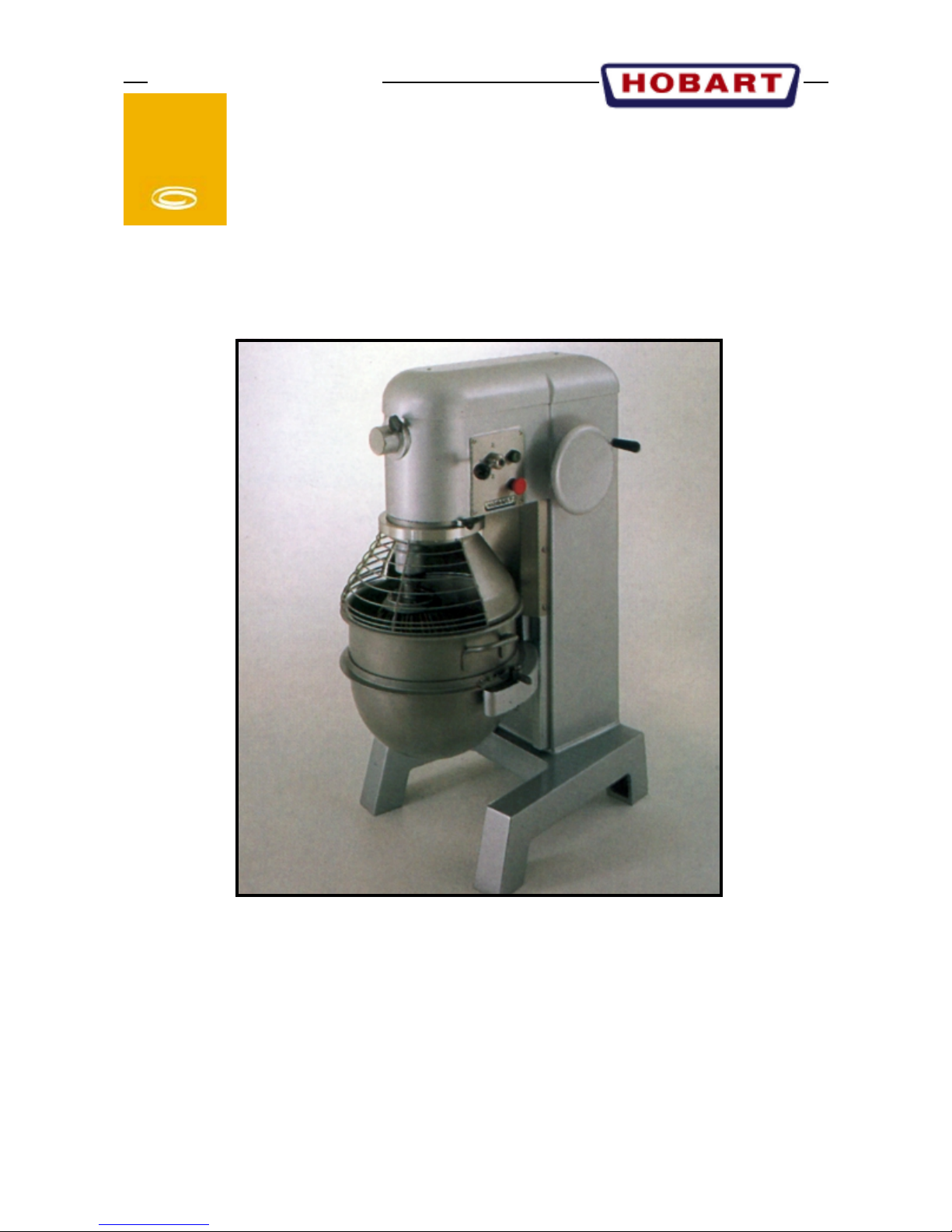
Model:H300
Mix er
Food Preparation
Page 2

UK. SERVICE TRAINING CENTRE
Warning this information is for HOBART STILL trained personnel only.
Reproduction of this information is prohibited without the written consent of HOBART STILL.
2/95
H300 - H400
MIXERS
Contents
GENERAL DATA ........................................................................................................................1
TRANSMISSION - SERVICE .....................................................................................................2
BOWL LIFT MECHANISM........................................................................................................3
WIRING DIAGRAMS .................................................................................................................4
Page 3

UK. SERVICE TRAINING CENTRE
Warning this information is for HOBART STILL trained personnel only.
Reproduction of this information is prohibited without the written consent of HOBART STILL.
Page: 1
2/95
H300 - 400
GENERAL DATA
Underside view of
Transmission
Drill 4.2 mm hole
and use a 5mm tap
to a depth of
10mm.
Pedestal
13.5 mm (x2)
Transmission case
Pedestal (front view)
FIG .1
FIG .2
EPM-E-11-4
EPM-E-11-8
EPM-E-11-17
137044
SCM-E-11-40
(x2)
Bowl support
EPM-E-11-8 EPM-E-11-17
FIG .1
Pedestal
Transmission
case
H300 - H400
240/50/1 - Fuse = 20a. 415/50/3 - Fuse = 6 amp
H300 = 0.75 kW. H400 = 0.75 kW
Bowl sizes
H300 = 29 litre
H400 = 39 litre
Bowl lift = Manual
Speeds = 3
Beater shaft speeds
1st - H300/400 = 68
2nd - H300/400 = 165
3rd - H300/400 = 274
Attachment Hub speeds
1st = 72. 2nd = 174. 3rd = 287
Lubricants
Gearbox = 6.8 kg Marfak multi purpose #2 grease.
Planetary = 113g Molytex #2 grease (+ bowl
screw)
Use light mineral oil on slideways.
Drill 3.3mm
and tap to
4mm (x2)
H300/400 BOWL GUARD RETROFIT INSTRUCTIONS. PARTS REQUIRED AS LISTED H300 =
ML36437. H400 = ML36438
1. ISOLATE AND DISCONNECT MACHINE FROM
MAINS ELECTRICAL SUPPLY.
2. REMOVE ALL EQUIPMENT
3. REMOVE DRIP CUP - DISCARD.
4. REMOVE PLANETARY INTERNAL GEAR - DISCARD
5. REMOVE BOWL SUPT/PEDESTAL COVER - DISCARD.
6. DRILL & TAP PEDESTAL (FIG 2.)
7. DRILL & TAP TRANSCASE (FIG 1.)
8. FIT BOWL SUPT SWITCH TO PEDESTAL AS DETAILED ( FIG .3)
9. FIT GUARD SENSOR SWITCH & HOUSING TO
TRANSCASE (USING 2 X M5 X 45 SCREWS).
10. FIT NEW BOWL SUPT/PEDESTAL COVER FIT
NEW INTERNAL GEAR.
11. ROTATE FRONT CAGE OF GUARD ASSEMBLY
OVER REAR SHIELD
12. LOCATE AND FIT GUARD ASSEMBLY BY HOLDING IN LOCKING PLUNGER AND LIFT GUARD ASSEMBLY, BY DRIP CUP SECTION, ONTO INTERNAL
GEAR THEN ROTATE CLOCKWISE, RELEASING
LOCKING PLUNGER, UNTIL LOCKED INTO POSITION.
13. CONNECT BOWL SUPT & GUARD SWITCHES (&
FUSE) INTO CONTROL CIRCUIT IN ACCORDANCE
WITH WIRING DIAGRAM
14. CONNECT RC SUPPRESSOR ACROSS TERMINALS Al/A2 OF CONTACTOR.
15. RECONNECT MACHINE TO MAINS ELECTRICAL SUPPLY AND TEST.
Page 4

UK. SERVICE TRAINING CENTRE
Warning this information is for HOBART STILL trained personnel only.
Reproduction of this information is prohibited without the written consent of HOBART STILL.
Page: 2
2/95
H300 - 400
TRANSMISSION - SERVICE
1. Remove Planetary.
2. Fit purpose made sleeve (1 1/4" ID plastic pipe) to
centre shaft and secure this with the Planetary bolt/
washer. The pipe will prevent Slow speed gear coming
apart.
3. Remove transmission cover complete.
4. Locate the Worm gear shaft and pull this out complete.
7. The Transmission shaft can now be lifted out, it may
be necessary to lift the Centre shaft slightly.
8. Remove shifter rod, slide shifter yoke to one side and
lift out the complete Centre shaft.
5. With the Worm gear shaft removed, go to the Bevel
gear and lift this off.
6. With the Bevel gear removed proceed to step 7.
TRANSMISSION SHAFT WORM GEAR SHAFT MOTOR PINIONCENTRE SHAFT
Slow speed gear
(built-in "sprag clutch")
Overhead view of Sprag clutch
as fitted inside Slow speed gear.
Page 5

UK. SERVICE TRAINING CENTRE
Warning this information is for HOBART STILL trained personnel only.
Reproduction of this information is prohibited without the written consent of HOBART STILL.
Page: 3
2/95
H300 - 400
BOWL LIFT MECHANISM
Upper stop screw:- adjust this up or down with the Beater fitted
to the machine to give adequate clearance betwen Bowl and
Beater.
Brass nut:- to remove this go to under side of Bowl yoke and
remove the lower stop bolt. Then ensure the Bowl yoke is wound
down as low as possible (protect paint work). The remove upper
stop screw and the retaining bolt. You will now be able to remove
the brass nut by turning the hand wheel thereby rotating the Bowl
lift screw.
Retaining bolt
Bowl lift screw
Helpfull tips
Q. Product left at base of bowl during mix.
A. Gap between Beater and Bowl is too great, adjust the upper stop screw.
Q. Bowl lift creeps down on it's own with product loaded bowl.
A. Too much product in bowl or the Brass nut is worn (see above to
replace).
Beater shaft kit = 142921 (H300/400)
comprises of the following;
52173 Beater Shaft
BB-E-3-41 Ball Bearing
RR-E-2-3 Retaining Ring
9608E Pin Beater Shaft
OS-E-2-14 Oil Seal
52174 Beater Pinion 18T
BB-E-3-31 Ball Bearing
SC-E-10-13 Grub Screw 3/8" UNC
SC-E-10-11 Grub Screw 3/8" UNC
WK-E-2-4 WoodruffKey
Page 6

UK. SERVICE TRAINING CENTRE
Warning this information is for HOBART STILL trained personnel only.
Reproduction of this information is prohibited without the written consent of HOBART STILL.
Page: 4
2/95
H300 - 400
WIRING DIAGRAMS
138724 start
138725 run
Stephan motor
232185-21
Brook motor 1.1 kw
Brook motor
1.1 kw
Example of Bowl lift and guard safety switches fitted
 Loading...