

Page 1
OM-2010
121585
Revised 121691
031893
OPERATION AND MAINTENANCE
MANUAL
with
ILLUSTRATED PARTS LIST
for
GPU-600
SOLID STATE TRANSFORMER-RECTIFIER
RATED OUTPUT: 28 V-DC, 600 A
SPECIFICATION INPUT VOLTAGE FREQUENCY MODEL NUMBER
S6883-1 208/230/460 V, 3-PHASE 60-Hz 6T28-600CL
S6883-2 220/380 V, 3-PHASE 50-Hz 5T28-600CL
S6883A-1 208/230/460 V, 3-PHASE 60-Hz 6T28-600CL
S6883A-2 220/380 V, 3-PHASE 50-Hz 5T28-600CL
S6883A-3 230/460/575 V, 3-PHASE 60-Hz 6T28-600CL
Manufactured by
HOBART BROTHERS COMPANY
POWER SYSTEMS GROUP
GROUND POWER EQUIPMENT
TROY, OHIO 45373
U.S.A.
Page 2

This page intentionally left blank
Page 3

SAFETY INSTRUCTIONS AND WARNINGS FOR ELECTRICAL POWER EQUIPMENT
WARNING
ELECTRIC SHOCK can KILL. Do not touch live electrical parts.
ELECTRIC ARC FLASH can injure eyes, burn skin, cause equipment damage, and ignite combustible
material. DO NOT use power cables to break load and prevent tools from causing short circuits.
IMPROPER PHASE CONNECTION, PARALLELING, OR USE can damage this and attached
equipment.
Important:- Protect all operating personnel. Read, understand, and follow all instructions in
the Operating/Instruction Manual before installing, operating, or servicing the equipment. Keep the
manual available for future use by all operators.
A. GENERAL
Equipment that supplies electrical power can cause serious injury or death, or damage to other equipment
or property. The operator must strictly observe all safety rules and take precautionary actions. Safe practices
have been developed from past experience in the use of power source equipment. While certain practices below apply only to electrically-powered equipment, other practices apply to engine-driven equipment, and
some practices to both.
B. SHOCK PREVENTION
Bare conductors, or terminals in the output circuit, or ungrounded, electrically-live equipment can fatally
shock a person. Have a certified electrician verify that the equipment is adequately grounded and learn what
terminals and parts are electrically HOT. Avoid hot spots on machine. Use proper safety clothing, procedures, and test equipment.
The electrical resistance of the body is decreased when wet, permitting dangerous currents to flow
through it. When inspecting or servicing equipment, do not work in damp areas. Stand on a dry rubber mat
or dry wood, use insulating gloves when dampness or sweat cannot be avoided. Keep clothing dry, and
never work alone
1. Installation and Grounding of Electrically Powered Equipment
Equipment driven by electric motors (rather than by diesel or gasoline engines) must be installed and
maintained in accordance with the National Electrical Code, ANSI/NFPA 70, or other applicable codes. A
power disconnect switch or circuit breaker must be located at the equipment. Check the nameplate for voltage, frequency, and phase requirements. If only 3-phase power is available, connect any single-phase rated
equipment to only two wires of the 3-phase line. DO NOT CONNECT the equipment grounding conductor
(lead) to the third live wire of the 3-phase line, as this makes the equipment frame electrically HOT, which can
cause a fatal shock.
Always connect the grounding lead, if supplied in a power line cable, to the grounded switch box or building ground. If not provided, use a separate grounding lead. Ensure that the current (amperage) capacity of
the grounding lead will be adequate for the worst fault current situation. Refer to the National Electrical Code
ANSI/NFPA 70 for details. Do not remove plug ground prongs. Use correctly mating receptacles.
2. Output Cables and Terminals
Inspect cables frequently for damage to the insulation and the connectors. Replace or repair cracked or
worn cables immediately. Do not overload cables. Do not touch output terminal while equipment is energized.
3. Service and Maintenance
This equipment must be maintained in good electrical and mechanical condition to avoid hazards stemming from disrepair. Report any equipment defect or safety hazard to the supervisor and discontinue use of
the equipment until its safety has been assured. Repairs should be made by qualified personnel only.
Before inspecting or servicing electrically-powered equipment, take the following precautions:
a. Shut OFF all power at the disconnecting switch or line breaker before inspecting or servicing the
equipment.
b. Lock switch OPEN (or remove line fuses) so that power cannot be turned on accidentally.
c. Disconnect power to equipment if it is out of service.
d. If troubleshooting must be done with the unit energized, have another person present who is trained in
turning off the equipment and providing or calling for first aid.
Page 4

C . FIRE AND EXPLOSION PREVENTION
Fire and explosion are caused by electrical short circuits, combustible material near engine exhaust pip-
ing, misuse of batteries and fuel, or unsafe operating or fueling conditions.
1. Electrical Short Circuits and Overloads
Overloaded or shorted equipment can become hot enough to cause fires by self destruction or by causing
nearby combustibles to ignite. For electrically-powered equipment, provide primary input protection to remove
short circuited or heavily overloaded equipment from the line.
2. Batteries
Batteries may explode and/or give off flammable hydrogen gas. Acid and arcing from a ruptured battery
can cause fires and additional failures. When servicing,do not smoke, cause sparking, or use open flame
near the battery.
3. Engine Fuel
Use only approved fuel container or fueling system. Fires and explosions can occur if the fuel tank is not
grounded prior to or during fuel transfer. Shut unit DOWN before removing fuel tank cap. DO NOT completely fill tank, because heat from the equipment may cause fuel expansion overflow. Remove all spilled
fuel IMMEDIATELY, including any that penetrates the unit. After clean-up, open equipment doors and blow
fumes away with compressed air.
D. TOXIC FUME PREVENTION
Carbon monoxide - Engine exhaust fumes can kill and cause health problems. Pipe or vent the exhaust
fumes to a suitable exhaust duct or outdoors. Never locate engine exhausts near intake ducts of air conditioners.
E. BODILY INJURY PREVENTION
Serious injury can result from contact with fans inside some equipment. Shut DOWN such equipment for
inspection and routine maintenance. When equipment is in operation, use extreme care in doing necessary
trouble-shooting and adjustment. Do not remove guards while equipment is operating.
F. MEDICAL AND FIRST AID TREATMENT
First aid facilities and a qualified first aid person should be available for each shift for immediate treat-
ment of all injury victims. Electric shock victims should be checked by a physician and taken to a hospital immediately if any abnormal signs are observed.
EMERGENCY FIRST AID
Call physician immediately. Seek additional assistance. Use First Aid techniques recommended
by American Red Cross until medical help arrives.
IF BREATHING IS DIFFICULT, give oxygen, if available, and have victim lie down. FOR ELECTRICAL
SHOCK, turn off power. Remove victim; if not breathing, begin artificial respiration, preferably mouth-tomouth. If no detectable pulse, begin external heart massage. CALL EMERGENCY RESCUE SQUAD IMMEDIATELY.
G. EQUIPMENT PRECAUTIONARY LABELS
Inspect all precautionary labels on the equipment monthly. Order and inspect all labels that cannot be
easily read.
Page 5

OM-2010
Table of Contents
SUBJECT CHAPTER/SECTION PAGE
WARNING
LIST OF EFFECTIVE PAGES
INTRODUCTION
CHAPTER 1. RECEIPT OF EQUIPMENT AND
INSTALLATION
SECTION 1. RECEIPT OF EQUIPMENT 1-1 1
SECTION 2. INSTALLATION 1-2 1
A. Location 1-2 1
B. Internal Wiring check 1-2 1
C. Connecting the Machine to Line Voltage 1-2 1
D. Grounding 1-2 2
E. Output Leads 1-2 3
F. Lub rication 1-2 3
CHAPTER 2. DESCRIPTION AND OPERATION
SECTION 1. DESCRIPTION 2-1 1
1. General 2-1 1
2. Special Features 2-1 3
3. Detailed Description 2-1 5
A. General 2-1 5
B. Main Transformer 2-1 5
C. Control Transformer 2-1 8
D. Auxiliary Power Circuitry 2-1 8
E. Output Contactor Circuitry 2-1 8
F. Output Filter Circuitry 2-1 9
G. Front Panel Control Components 2-1 9
(1) Output Meter 2-1 9
(2) Input Contactor Switch with Light 2-1 9
(3) Output Contactor Switch and Light 2-1 9
(4) Overload Trip Light 2-1 10
H.Main SCR Heat Sink Assembly 2-1 10
J. Solid State Printed Circuit Control Board 2-1 10
April 10/89 Revised Table of Contents
Page 1
Page 6

OM-2010
SUBJECT CHAPTER/SECTION PAGE
(1) Electronic Overvoltage/Overload Trip Circuit 2-1 10
(2) Electronically Controlled Current Limit 2-1 10
(3) Regulated DC Output Voltage 2-1 10
(4) Thermal Overload Trip 2-1 11
SECTION 2. OPERATION 2-2 1
1. General 2-2 1
2. Preparation for Operation 2-2 1
3. Operation Procedure 2-2 2
A. Input Control Functions 2-2 2
B. Output Control Functions 2-2 2
C. Voltmeter 2-2 2
D. Output Current Limit 2-2 2
CHAPTER 3. SERVICING
SECTION 1. MAINTENANCE 3-1 1
1. General 3-1 1
2. Inspection 3-1 1
3. Lubrication 3-1 1
4. Parts Replacement 3-1 2
A. Minor electrical components 3-1 2
B. Major Electrical Components 3-1 2]
Section 2. INSPECTION CHECK
AND REPAIR 3-2 1
1. General 3-2 1
2. Exterior Cables and Connections 3-2 1
A. Input and Output Cables 3-2 1
B. Cable Connections 3-2 1
3. Controls and Instruments 3-2 1
A. Voltmeter, Ammeter and Control Switches 3-2 1
B. Indicating Lights 3-2 1
(1) Power input and output lights 3-2 1
(2) Overload trip indicating light 3-2 2
C. Overload Thermostat 3-2 2
D. Starting Current Limit Potentiometer 3-2 2
E. Contactors 3-2 4
(1) Output Contactor, K2 3-2 4
(2) Input Contactor, K1 3-2 4
F. Control Transformer 3-2 4
4. Major Components Check and Repair 3-2 4
A. Main Power Transformer 3-2 4
B. Silicon Controlled Rectifier Assembly and
Flyback Diode 3-2 5
Table of Contents April 10/89 Revised
Page 2
Page 7

OM-2010
SUBJECT CHAPTER/SECTION PAGE
(1) Visual 3-2 5
(2) Voltohmmeter 3-2 5
(3) Voltage Test for SCR Assembly 3-2 6
C. Filter Choke and Capacitor Voltage Test 3-2 6
D. Printed Circuit Control Board 3-2 6
SECTION 3. CALIBRATION AND TEST
OF PC CONTROL BOARD 3-3 1
1. General 3-3 1
2. Printed Circuit Board Test Values and
Adjustments 3-3 1
SECTION 4. TROUBLESHOOTING 3-4 1
1. General 3-4 1
2. Troubleshooting 3-4 1
3. Equipment for Troubleshooting 3-4 2
4. Safety 3-4 2
5. Voltages of Interest 3-4 2
6. SCR Malfunction Instructions 3-4 3
A. Normal SCR Malfunction Conditions 3-4 3
B. Severe SCR Malfunction Conditions 3-4 3
C. SCR tests or checks 3-4 3
CHAPTER 4. ILLUSTRATED PARTS LIST
SECTION 1. INTRODUCTION 4-1 1
1. General 4-1 1
2. Purpose 4-1 1
3. Arrangement 4-1 1
4. Explanation of Parts List 4-1 1
A. Contents 4-1 1
B. Parts List Form 4-1 2
(1) “FIGURE-ITEM NO.” Column 4-1 2
(2) “HOBART PART NUMBER” Column 4-1 2
(3) “NOMENCLATURE” Column 4-1 2
(4) “EFF” (Effective) Column 4-1 2
(5) “UNITS PER ASSEMBLY” Column 4-1 2
SECTION 2. MANUFACTURER’S
CODES 4-2 1
1. Explanation of Manufacturer’s (Vendor)
Code List 4-2 1
April 10/89 Revised Table of Contents
Page 3
Page 8

OM-2010
SUBJECT CHAPTER/SECTION PAGE
SECTION 3. PARTS LIST 4-3 1
1. Explanation of Parts List Arrangement 4-3 1
2. Symbols and abbreviations 4-3 1
SECTION 4. NUMERICAL INDEX 4-4 1
1. Explanation of Numerical Index 4-4 1
CHAPTER 5. OPTIONAL EQUIPMENT
CHAPTER 6. MANUFACTURER’S LITERATURE
UNUSUAL SERVICE CONDITIONS
Table of Contents April 10/89 Revised
Page 4
Page 9

LIST OF EFFECTIVE PAGES
CHAPTER/ CHAPTER/
SECTION PAGE DATE SECTION PAGE DATE
List of 3-2 4 Apr 10/89
Effective 3-2 5 Apr 10/89
Pages 1/2 Apr 10/89 3-2 6 Apr 10/89
3-2 7 Apr 10/89
Introduction 1 Apr 10/89 3-2 8 Apr 10/89
Introduction 2 Apr 10/89
Introduction 3 Apr 10/89 3-3 1 Apr 10/89
Introduction 4 Apr 10/89 3-3 2 Apr 10/89
3-3 3 Apr 10/89
Contents 1 Apr 10/89 3-3 4 Apr 10/89
Contents 2 Apr 10/89 3-3 5 Apr 10/89
Contents 3 Apr 10/89 3-3 6 Apr 10/89
Contents 4 Apr 10/89 3-4 1 Apr 10/89
1-1 1 Apr 10/89 3-4 2 Apr 10/89
1-1 2 Apr 10/89 3-4 3 Apr 10/89
3-4 4 Apr 10/89
1-2 1 Apr 10/89 3-4 5 Apr 10/89
1-2 2 Apr 10/89 3-4 6 Apr 10/89
1-2 3 Apr 10/89 3-4 7 Apr 10/89
1-2 4 Apr 10/89 3-4 8 Apr 10/89
3-4 9 Apr 10/89
2-1 1 Apr 10/89 3-4 10 Apr 10/89
2-1 2 Apr 10/89 3-4 11 Apr 10/89
2-1 3 Apr 10/89 3-4 12 Apr 10/89
2-1 4 Apr 10/89
2-1 5 Apr 10/89 4-1 1 Apr 10/89
2-1 6 Apr 10/89 4-1 2 Apr 10/89
2-1 7 Apr 10/89 4-1 3 Apr 10/89
2-1 8 Apr 10/89 4-1 4 Apr 10/89
2-1 9 Apr 10/89
2-1 10 Apr 10/89 4-2 1 Apr 10/89
2-1 11 Apr 10/89 4-2 2 Apr 10/89
2-1 12 Apr 10/89 4-2 3 Apr 10/89
4-2 4 Apr 10/89
4-3 1 Apr 10/89
2-2 1 Apr 10/89 4-3 2 Apr 10/89
2-2 2 Apr 10/89 4-3 3 Apr 10/89
2-2 3 Apr 10/89 4-3 4 Apr 10/89
2-2 4 Apr 10/89 4-3 5 Apr 10/89
4-3 6 Apr 10/89
3-1 1 Apr 10/89 4-3 7 Apr 10/89
3-1 2 Apr 10/89 4-3 8 Apr 10/89
4-3 9 Apr 10/89
3-2 1 Apr 10/89 4-3 10 Apr 10/89
3-2 2 Apr 10/89 4-3 11 Apr 10/89
3-2 3 Apr 10/89 4-3 12 Apr 10/89
OM-2010
April 10/89 Revised List of Effective Pages
Page 1
Page 10

OM-2010
LIST OF EFFECTIVE PAGES
CHAPTER/
SECTION PAGE DATE
4-4 1 Apr 10/89
4-4 2 Apr 10/89
4-4 3 Apr 10/89
4-4 4 Apr 10/89
5-0 1 Apr 10/89
5-0 2 Apr 10/89
List of Effective Pages April 10/89 Revised
Page 2
Page 11

INTRODUCTION
1. General
This Introduction is intended to give the reader a better understanding of how to use the manual properly.
The manual can be very helpful to you if you will READ THIS INTRODUCTION FIRST. READ AND UN-
DERSTAND THE MANUAL BEFORE ATTEMPTING TO OPERATE, INSTALL, OR REPAIR THIS
EQUIPMENT.
2. Scope
The manual covers a solid state controlled transformer-rectifier, 600 A DC ground power unit having the
Specification Numbers listed. It gives a detailed description of the equipment and includes information covering operation, installation, troubleshooting and repair.
3. Purpose
OM-2010
The manual’s purpose is to provide information and instructions to experienced operators, electricians,
and repairmen who have never seen or operated this equipment. It is the intent of the manual to guide
and assist operators and maintenance personnel in the proper use and maintenance of the equipment.
4. Contents
Immediately following the Introduction is a List of Effective Pages which lists each page in the manual by
its Chapter/Section, and page number. Directly opposite each page number listing is a date which indicates whether the page is original or revised.
A complete Table of Contents appears next in sequence. It contains a list of all Chapters, Sections, and
the principal paragraph titles within each Section. The location of each listing is identified by Chapter/Section and page number. A complete list of illustrations with their location is located at the end of the Table
of Contents.
The main text of the manual is divided into five Chapters as follows:
Chapter 1. Receiptand Installation Instructions
Chapter 2. Description and Operation
Chapter 3. Servicing
Chapter 4. Illustrated Parts List with Index
Chapter 5. Optional Equipment
Chapter 6. Manufacturer’s Literature
Each Chapter is divided into as many Sections as necessary. Sections are always referred to by a combination Chapter/Section number. Example, 2-3 refers to Chapter 2, Section 3.
April 10/89 Revised Introduction
Page 1
Page 12

OM-2010
5. Format
A. Paragraphing and Outlining
The material within each Section is divided into main subjects with applicable paragraph headings
and sub-headings as required. This method not only helps keep information closely knit, but provides
a means of identifying material for reference purposes. For example, a portion of the Description Section might logically follow this arrangement and paragraphing:
1. Control A. Interior Panel
(1) Protective devices
(a) Overload relay
(2) Contactors
B. Page Numbering
Page numbers do not run consecutively throughout the manual. Each page is identified by the Chapter/Section number in which it appears, and by a page number within the Chapter/Section. Therefore,
the first page in each Section is page 1. These identifying numbers appear in the lower, outside corner of each page. Each page also bears a date located in the corner opposite the page number. This
date is either that of original issue, or of the latest revision. Any revision to the original text is identified
by a heavy black line in the left-hand margin. Illustrations follow a numbering system similar to page
numbering. The first Figure in each Section is Figure 1.
6. How to Use the Manual
A. General
This manual follows the format, rules and style proposed by, and generally accepted by members of
the Air Transport Association. Insofar as possible, information is grouped to help the user locate it
quickly. All tables, charts, diagrams, etc., as well as illustrations, are identified by Figure Number
Fig. 2)
B.How to Locate Information
Even if you have read the manual completely and thoroughly, the easiest and quickest way to locate
information is by using the Table of Contents. Look for new and added information at the end of the
section in which it is normally found.
(1) Table of Contents
to avoid confusion.
The complete Table of Contents is relatively short. Even if the user has no idea where a certain
bit of information is located, the general location can be quickly found by running through the Table of Contents. For example, some adjustment information is needed. A quick look at the Table
of Contents indicates that Adjustment/Test information is located in 3-3
(i.e.,
(Chapter 3, Section 3).
Introduction April 10/89 Revised
Page 2
Page 13

(2) List of Illustrations
A complete list of Illustrations follows the Table of Contents and includes the title, figure number,
and Chapter/Section, with page number location of all illustrations contained in the manual. Locate the appropriate title in the List of Illustrations, then turn to the Chapter/Section and page
number indicated. A complete set of electrical schematic and connection diagrams is included in
Chapter 5.
(3) References
To avoid repetition and lengthy explanations, references to other material are used throughout
the manual. Both material in the text and illustrations may be referred to in order to clarify or expand information and instructions. Portions of the text are referred to by identifying the paragraph
in which referenced material may be found. A reference to other material would be in order here
by referring to paragraphing information contained in paragraph 5, A above. When referenced material is located in the same Chapter/Section as the reference, only the paragraph identification is
given.
Example:
OM-2010
(Ref. Para. 1, A)
means the material is to be found in paragraph 1, A, of the same Chap-
ter/Section.
When referenced material is located in another Chapter/Section, both the Chapter/Section
number and the paragraph identification are given.
Example:
(Ref. 1-2, Para. 1, A)
means that the referenced material is located in Chapter/Section 1-2,
and identified by paragraph 1, A.
Components shown in illustrations and illustrations themselves are referenced in a similar manner. When this type reference is made, the item number of the part and the Figure number in
which it appears are given.
Example:
(Ref. 2, Fig. 3)
refers to item number 2 which appears in illustration Figure 3 of the same
Chapter/Section.
When the referenced Figure appears in another Chapter/Section, the reference will include the
Chapter/Section number.
April 10/89 Revised Introduction
Page 3
Page 14

OM-2010
Example:
(Ref. 2-3; 1, Fig. 4)
4.
Once a Figure number reference has been established for a series of instructional steps, the Figure number is not repeated. Only the item numbers of parts involved are referenced.
For example, an instruction might appear like this: “Loosen screw
(4),
tor
When an item is referenced without a figure number, it will always apply to the last preceding
Figure number mentioned in the text.
and remove brush
tells the user to refer to Chapter/Section 2-3, and to see item 1, in Figure
(2, Fig. 6),
slide out connec-
(6)”.
NOTE 1: The word Seemay appearin some references,as (SeeFig. 2). It means exactlythe samething
as Ref., however, its usage seems a little more direct and definite.
NOTE 2: When an “output cable” is mentioned in the manual, it refers to a large cable used to carry
output current. A special connector for the two output leads and the ground lead may be required when
delivering power directly to an aircraft.
7. SERVICE
If you have any questions concerning your Hobart Power Systems Division equipment, please contact
our Service Department by mail, telephone or FAX.
Write: Hobart Brothers Company
Power Systems Group
Service Department
Troy, Ohio 45373
U.S.A.
Call: Area Code (513) 339-5060
FAX: 513-339-4219
Introduction April 10/89 Revised
Page 4
Page 15

OM-2010
CHAPTER 1. RECEIPT OF EQUIPMENT
AND INSTALLATION
SECTION 1. RECEIPT OF EQUIPMENT
Check the equipment received against the Hobart Brothers Company invoice to make certain that the
shipment is complete and undamaged. If the equipment has been damaged in transit, notify the carrier
(railroad, trucking company, etc.)
damage claim, furnish Hobart Brothers Company with full information about the claim. If the shipment is in
error, contact Order Department, Hobart Brothers Company, Power Systems Division, Troy, Ohio 45373.
Give the MODEL, SPECIFICATION, and SERIAL numbers of the equipment, and a full description of the
parts in error. Refer to the title of this manual for a listing of the specification numbers this manual describes.
An identification and rating nameplate is normally located on the power supply front panel for your
convenience. If the rated input or output voltages do not agree with your requirements, contact the order
department for instructions or corrective action.
Generally, it is good practice to move the equipment to the site of installation before uncrating or unpacking .
Take care to avoid damage to the equipment if bars, hammers, etc., are used. Lifting eyes which extend
through the top of the cabinet have been provided to facilitate handling with a crane or hoist. Be certain the
crane or hoist is adequate for the task.
Best results will be obtained with this equipment ONLY if the responsible operating personnel have access to
this manual, and are familiar with these instructions. Additional copies may be obtained at a small cost per
copy by writing to: Hobart Brothers Company, Power Systems Division, Troy, Ohio Supply the owner’s
manual no.
(OM-2010)
plus the model, specification, and serial numbers of your equipment.
at once and file a claim for damages. If you require assistance with a
April 10/89 Revised 1-1
Page 1
Page 16
OM-2010
1-1 April 10/89 Revised
Page 2
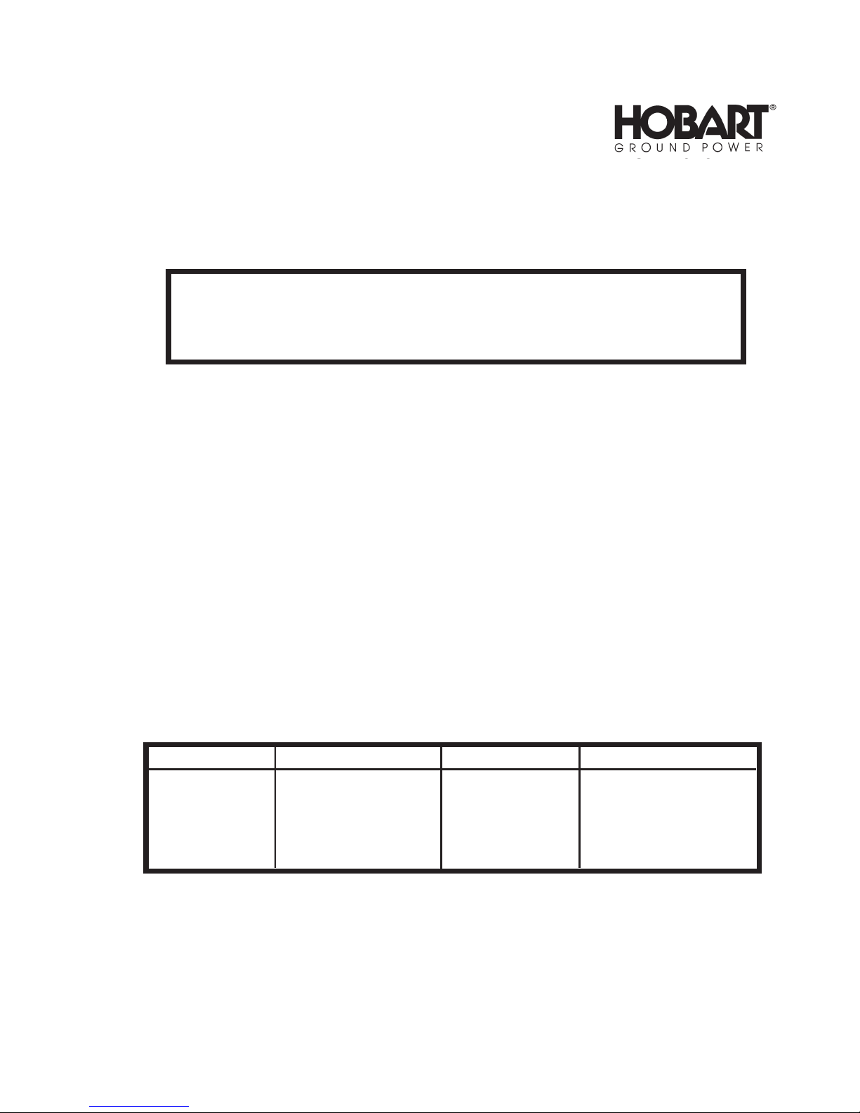
installation Dimension Drawing
Figure 1
Page 17

OM-2010
SECTION 2. INSTALLATION
A. Location
For best operating characteristics and longest unit life, select an installation site that is not exposed to
high humidity, dust, high ambient temperature, flooding, or corrosive agents. Moisture can condense on
electrical components, causing corrosion or shorting of circuits. Dirt on components helps retain this moisture in addition to providing a conducting material.
Adequate air circulation is needed at all times in order to assure proper operation. Provide a minimum of
12 inches
ings are not obstructed.
(305mm)
of free air space at both front and rear of the unit. Make sure that the ventilator open-
B. Internal Wiring check
Refer to the product identification plate
power input voltages and frequency at which it will be operated.
(nameplate)
on the machine’s control panel to determine the
WARNING: ELECTRIC SHOCK CAN KILL. OPEN THE DISCONNECT SWITCH,
OR BREAKER, AND DETERMINE THAT NO VOLTAGE IS PRESENT, BEFORE
CONNECTING WIRES BETWEEN THE INPUT SERVICE AND POWER SUPPLY
OR WORKING ON THE POWER SUPPLY.
CAUTION: RECONNECTION OF CONTROL TRANSFORMER AS WELL AS MAIN INPUT CONNECTION PANEL MUST BE MADE WHEN CHANGING RATED INPUT VOLTAGE. SEE CHANGEOVER DIAGRAM.
Remove cabinet top for access to LINE VOLTAGE MAIN CHANGEOVER circuitry. Check line voltage
connections against instructions on the VOLTAGE CHANGEOVER DIAGRAM supplied with this manual.
If necessary, rearrange internal wiring and/or link connections to agree with the requirements for your input.
C. Connecting the Machine to Line Voltage
The input power should be connected to the input terminals on the lifting baffle via a suitable disconnecting means furnished by the user. Select the proper sized knock-out hole provided in the rear panel of the
machine to allow for the entry of the input conductors. Be certain the cable inside the power supply will
not contact the fan or hot parts. The lower holes may give a bit less weather leakage.
CAUTION: THE METHOD OF INSTALLATION, CONDUCTOR SIZE, AND OVERCURRENT PROTECTION SHALL CONFORM TO THE REQUIREMENTS OF THE LOCAL ELECTRICAL CODE,
THE NATIONAL ELECTRICAL CODE, OR OTHER NATIONAL CODES, AS APPLICABLE. ALL INSTALLATION WIRING AND MACHINE RECONNECTION SHALL BE DONE BY QUALIFIED PERSONS.
April 10/89 Revised 1-2
Page 1
Page 18

OM-2010
Figure 1 provides minimal information for selection of line conductors, overcurrent protection, and the
equipment grounding conductor. This information is from the National Electrical Code NFPA 70-1981 Edition. Install this equipment per the latest edition, available from the National Fire Protection Association,
470 Atlantic Avenue, Boston, MA 02210.
Connect the three-phase line leads to terminals L1, L2, and L3 on the line contactor (top end) located on
the rear of the lifting baffle inside the power supply cabinet.
NOTE: After connecting the input cables, it is recommended that Hobart #904021 urethane coating be
sprayed on the connections at the line contactor to protect these connections from corrosion, fungus,
and contamination. Spraying these connections will also reduce the potential for arcing from dirt and
condensation.
Copper Copper
Rated Line Wire Size * Grounding
Line Amps Conductor
Volts In Conduit Flexible Cable Min. Size
208 86 No. 3 No. 3 No. 3
230 78 No. 4 No. 4 No. 4
460 39 No. 8 No. 8 No. 8
220 82 No. 4 No. 4 No. 4
380 47 No. 8 No. 8 No. 8
230 79 No. 4 No. 4 No. 4
460 39 No. 8 No. 8 No. 8
575 32 No. 8 No. 8 No. 8
Recommended Wire Size Table
Figure 1
* Conductor sizes listed are for 30 feet or less of each conductor in conduit and for conductors having
90C insulation, such as type FEP, FEPB, RHH, and THHN. For conductors having other insulation, or for
conductors longer than 30 feet, consult Hobart Brothers Company as to size required.
D. Grounding
The frame of this ground power unit should be grounded for personnel safety, and to assure operation of
the overcurrent protection. The grounding method, and the equipment grounding conductor size and type
shall conform to local and national codes. For the National Electrical Code, the equipment grounding conductor shall be green, green with a yellow stripe, or bare. If flexible power cable is used, use a cable assembly which includes the equipment grounding conductor. If metallic armored cable or conduit is used,
the metal sheathing or conduit must be effectively grounded per local and national codes.
Rubber-tire mounted equipment shall be grounded to conform to local national codes. The grounding assists in providing protection against line voltage electrical shock and static shock. The grounding serves to
discharge the static electric charge which tends to build up on rubber-tire mounted equipment. This static
charge can cause painful shock and lead to the erroneous conclusion that an electrical fault exists in the
equipment. An ungrounded cabinet can be at a lethal potential if a component fails electrically to the case.
1-2 April 10/89 Revised
Page 2
Page 19

OM-2010
Ifa system groundis not available,consult the electricalcodeenforcementbodyfor instructions. The
groundpower unit shouldbe connectedperyour electricalcode to an adequate drivengroundrodor to a
waterpipethatentersthe groundnot morethan 10 feet
Theequipmentgroundingconductor size listed inFig.1 is a guideif no local ornationalcode is applicable.
Attachthe equipmentgrounding blockconductor to the stud providedadjacent to the fuse block.Deter-
mine that the groundwire sizeis adequate beforethe machineisused.
CAUTION:FOR SAFETYAND TO ASSUREADEQUATEVENTILATION,BESURETOREPLACECABINETTOP.
(3 meters)
from the machine.
E. OutputLeads
Useyourapplicable electrical codeto determinethe minimumsizeoutputcable youneed. Ifthe cablevoltage dropis too largewiththe minimum size cable, usea largersize cable. For example, the 90C rated insulation, 4/0 cablein a 40 C ambientneededfor 400ADC mayhave to be largerfor carryingthat
amperageover200 feet withless than 4.5 Voltscabledrop.
April10/89Revised 1-2
Page3
Page 20

OM-2010
This page intentionally left blank.
1-2 April 10/89 Revised
Page 4
Page 21

CHAPTER 2. DESCRIPTION AND
OPERATION
SECTION 1. DESCRIPTION
1. General
OM-2010
This manual describes a portable,
ply rated at a continuous output of 28-V, 600-A DC to an aircraft load or a battery load. The rated input
voltages, currents, and frequency along with weights and dimensions are given in the Specifications and
Capabilities Table in Figure 2. This book will generally refer to this equipment as a GPU-600 power supply or power supply. See Figure 1 for a descriptive drawing showing the major components or sub-assemblies generally present in the design. A detailed description of each design variation is given later.
The power supplies are usually identical or nearly so in appearance. The specification numbers relate to
different rated input power requirements, possible output rating changes, or limited component specification changes. The specification number consists of the number S
dash number added for each specification change, i.e., S6683-1 or 6883A-1 is the first design specification made in the series.
The phase angle control method for obtaining the DC output voltage is the use of silicon controlled rectifiers to select the desired portion of the voltage that has been stepped down by the main transformer to produce the DC voltage. As shown in Figure 1, the power supply consists of:
A. A punched and formed steel base
rear and steerable castor wheels
B. A formed and louvered steel front panel
ters.
C. A formed and louvered sheet steel rear panel
and the SCR assembly
(see Fig. 1)
(17, Fig. 3)
Solid State controlled, transformer-rectifier DC power sup-
(for specification)
(1, Fig. 1)
(3)
at the front.
are mounted inside the power supply.
with 10 inch
(4)
for mounting most of the accessible controls and me-
(5, Fig. 1)
(254 mm)
to which the fan assembly
6683 or 6883A with a
diameter wheels
(2)
near the
(18, 19, Fig. 3)
D. A sheet steel top panel
put terminal board
the input power is off.
E. A sheet steel left side panel
panel permits output cable connections.
F. A sheet steel right side panel
board
(9, Fig. 1)
ble hangers also mount to this panel.
G. A steel vertical lifting yoke
and rear panels.
April 10/89 Revised 2-1
(16, Fig. 3),
and to the fuse block on the silicon controlled rectifier assembly
(7, Fig. 1 and 15, Fig. 3)
snubber board
(11, Fig. 3),
(8, Fig. 1)
(3, Fig. 3)
(1, Fig. 5)
to which two cable hangers are mounted. A door in this
with access doors to the solid state control printed circuit
with baffle assembly attached to the base between the front
removable for access to the input fuses, main in-
and control transformer connections when
(10, Fig. 1)
. Two ca-
Page 1
Page 22
OM-2010
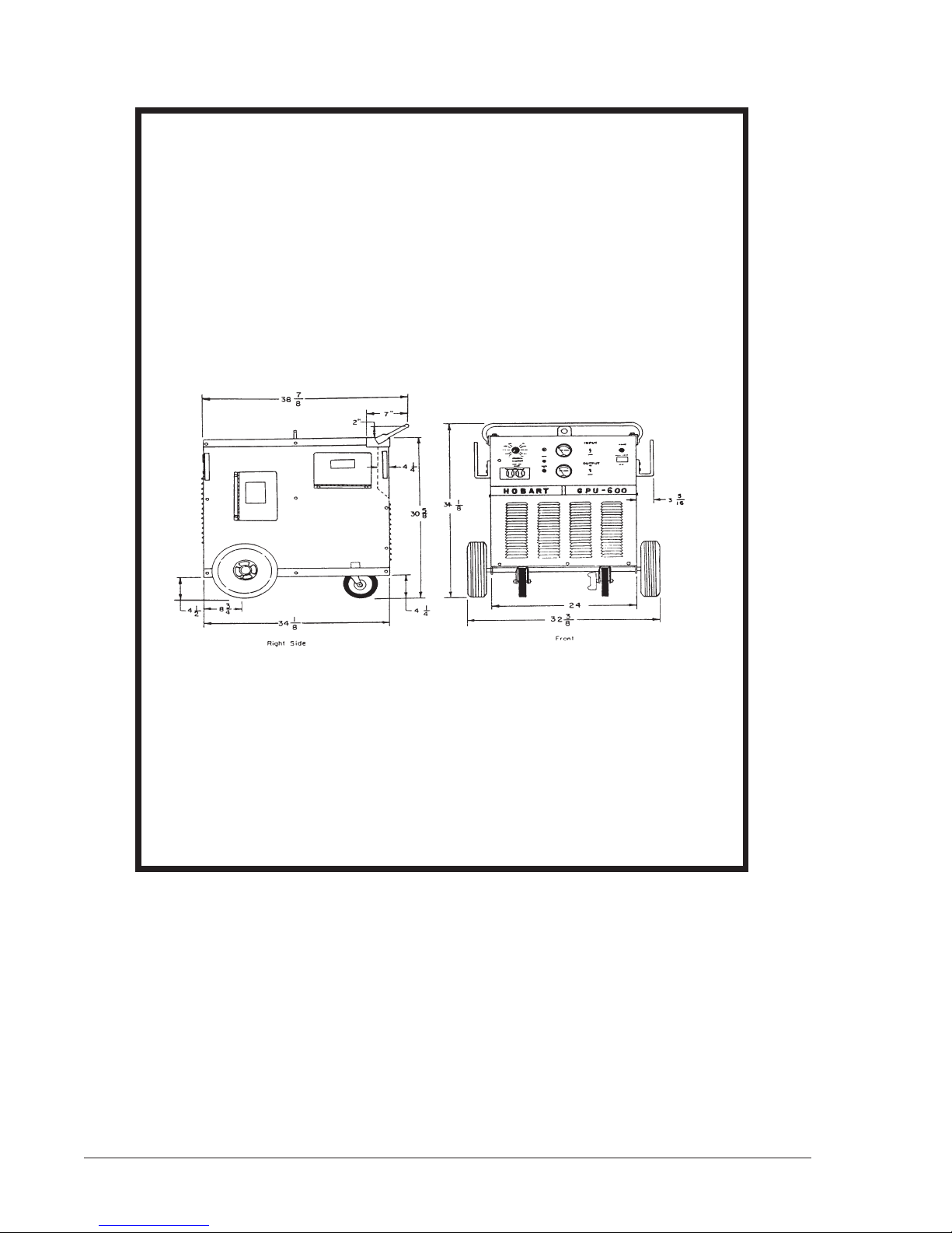
1. Mounting Base 8. Side Panel (Right
2. Wheel Side Illustrated)
3. Caster 9. Front Access Door
4. Front Panel 10. Rear Access Door
5. Rear Panel 11. Lifting Yoke
6. Cable Hanger 12. Power Receptacle
7. Top Panel
General Assembly of GPU-600 Power Supply
2-1 April 10/89 Revised
Page 2
Figure 1
Page 23

OM-2010
H. Various internal components such as the preload resistors
filter capacitors
Fig. 3)
input contactor
CAUTION: CAPACITOR CHARGE CAN INJURE! ALLOW CAPACITORS TO DISCHARGE AND
VERIFY CAPACITOR DISCHARGE WITH VOLTMETER BEFORE TOUCHING THE CAPACITOR
CIRCUITRY.
output contactor, control transformer
(4, Fig. 3)
(14, Fig. 3),
with the bus bar
etc.
(5, Fig. 3)
(10, Fig. 3),
at the front, filter reactor
(6, Fig. 3),
main transformer
(7, Fig. 3),
and printed circuit control board
(1, Fig. 3),
two
(13, Fig. 3),
2. Special Features
This DC ground power supply has the following special features which may be described more fully, if required, in the detailed description:
A. Output Ammeter, M1,
signal is provided by R11 meter shunt
B. Output Voltmeter, M2,
C. Input contactor,
D. 28-V DC contactor
E. Solid state closed loop feedback output voltage control to compensate for brown-outs and load re-
lated power supply voltage droop.
(2, Fig. 4)
(3, Fig. 4)
(14, Fig. 3)
(8, 9, Fig. 3)
with a 0-2000 A DC scale for reading the DC output amperes. The
(20, Fig. 3).
having a 0 to 50 V DC scale reading the DC output voltage.
with amber input contactor on-off light
with green output contactor on-off light
(12, Fig. 4)
(13, Fig. 4).
(8, 9,
F. Output overvoltage
G. Adjustable solid state output limit circuitry. The customer selects the momentary output limit in the
250 to 2000 A DC range by adjusting the R13 starting current potentiometer
age slope circuit causes a 25 percent drop in output voltage from 600 A DC to 1600 A DC output current.
CAUTION: EXCESSIVE CHARGING CURRENT CAN DAMAGE SOME TYPES OF BATTERIES
AND SOME OTHER LOADS. IF THE 250 A DC “STARTING SURGE” LEVEL IS TOO HIGH FOR
YOUR PARTICULAR LOAD, CONTACT THE MANUFACTURER FOR RECOMMENDATIONS.
H. Auxiliary power receptacle
this is a duplex receptacle rated at 115 V AC, 9-amperes, single phase. On the 50-Hz model, this is a
single output rated at 220 V AC, 15-amperes, single phase.
J. Thermal overload thermostat
overheats.
(31.5 V DC)
(5, Fig. 4)
(3, Fig. 5)
and overcurrent turn off circuitry and turn on DS2 trip light.
(8, Fig. 4).
with weather protection cover
which turns off the output voltage when the SCR heatsink
(7, Fig. 4)
A preset volt-
On the 60-Hz model,
April 10/89 Revised 2-1
Page 3
Page 24

OM-2010
PHYSICAL
Weight (approximately) 650 pounds (295 kg)
Length 38 1/8 inches (968 mm)
Width 32 3/4 inches (832 mm)
Height (overall) 34 1/8 inches (867 mm)
ELECTRICAL SPECIFICATION NUMBER
INPUT S6883-1 S6883-2
S6883A-1 * S6883A-1 * S6883A-1 *
Cycles per second 60 50 60
Phase 3 3 3
Volts 208/230/460 220/380 230/460/575
Amperes 86/78/39 82/47 79/39/32
Power Factor at 28-V DC
output .68 .68 .68
Ground cable size See1-2 Fig. 2 See 1-2 Fig. 2 See 1-2 Fig 2
OUTPUT
Output Power Rating (max.) 17.1 KW 17.1 KW 17.1KW
Volts 28.5 V DC 28.5 V DC 28.5 VDC
Amperes (rated load) 600 A DC 600 A DC 600A DC
Duty cycle 100 % 100% 100%
Overload Capacity 125% of rated 125% of rated 125% of rated
load for 7 load for 7 load for 7
minutes. minutes. minutes.
* Series S6683A units are identical to corresponding Series 6683 units except for the PC control board assemblies. PC control board No. 180294 is used in Series S6683 units, and PC control board No. 180294A is used in Series S6683A units.
K. Input contactor coil fuse F8,
(F9)
for auxiliary power on 50 Hz.
L. Running gear consisting of two 10"
and two swivel mounted 6"
mounted near the front. A handle for pulling or guiding is fastened to the top front of the power supply.
(20, Fig. 3),
(152.4 mm)
auxiliary power and fan fuse F1
(254 mm)
diameter casters
diameter wheels
(3, Fig. 1),
(9, Fig. 4).
(2, Fig. 1)
one with a manual brake,
on the axle near the rear
Fuse, 10 amp
2-1 April 10/89 Revised
Page 4
Page 25

3. Detailed Description
A. General
A detailed description of the parts used to build the power supply is given below. If a description applies only to power supplies having a particular specification number, reference to that specification
will be made. The specification number and equipment rating information is provided on the nameplate located on the power supply front panel just above the manufacturers name. Be certain that the
specification number and rating is proper for your input power rating. Also be sure that your output
voltage setting is properly rated for your load. Refer also to Figure 2 of this chapter for the tabulation
of rated values for the specifications listed.
This power supply utilizes solid state devices to control the output of the main transformer by delaying
the turn on time of the main siliconcontrolled rectifier to that required to give the desired power supply
output voltage. This control method is called SCR phase angle control.
The turn on delay after the voltage input to the SCR devices is quite similar to a phase shift. Generally, the longer the turn-on delay
factor. The printed circuit board has various data sent to it from sensors and/or points in the power
supply. These data are compared with the commands that the user has established so that instructions to correct any abnormality in output can be automatically provided.
(i.e., lower output voltage)
OM-2010
the lower the power supply input power
B. Main Transformer (1, Fig. 3)
The main power transformer is a forced air cooled, core-type, 3 phase unit that reduces the rated input voltage or voltages to a voltage somewhat higher than the maximum rated output voltage. The extra voltage for the output provides a reserve capability to compensate for undervoltage on the input
circuit, for the higher IR voltage drop found as the transformer, cables and other components heat up
with load and ambient temperature rises.
April 10/89 Revised 2-1
Page 5
Page 26
OM-2010
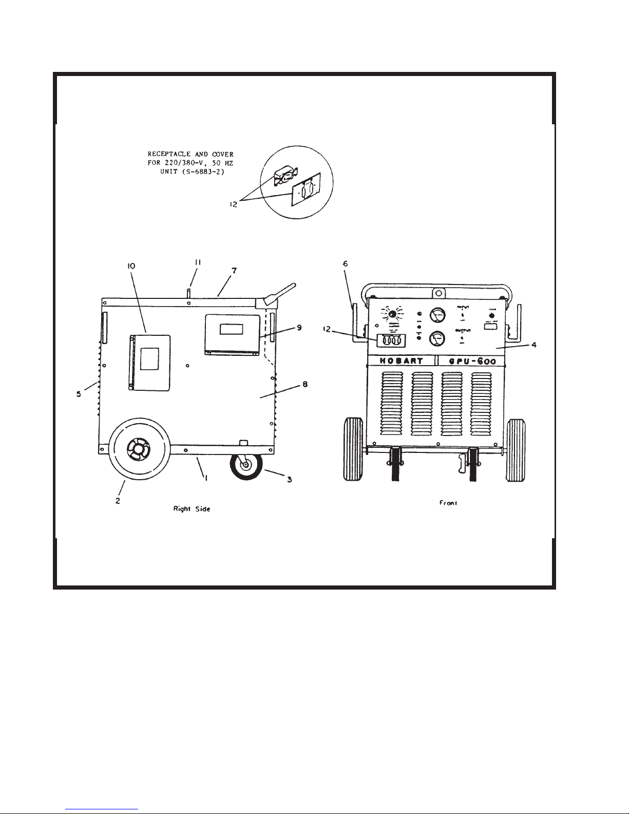
1. Power Transformer 12. PC Mounting Panel
2. Left Side Panel 13. Printed Circuit Board
3. Lifting Yoke 14. Line Contactor
4. Capacitor 15. Top Panel
5. Terminal Output Assembly 16. Voltage Changeover Board
6. Resistor Assembly 17. SCR Heat Sink Assembly
7. Choke 18. Fan Blade
8. (Deleted) 19. Fan Motor
9. 28 V-DC Contactor 20. Control Transformer Fuse
10. Control Transformer 21. Ammeter Shunt
11. Right Side Panel
2-1 April 10/89 Revised
Page 6
Internal Components for GPU-600
Figure 3
Page 27
OM-2010
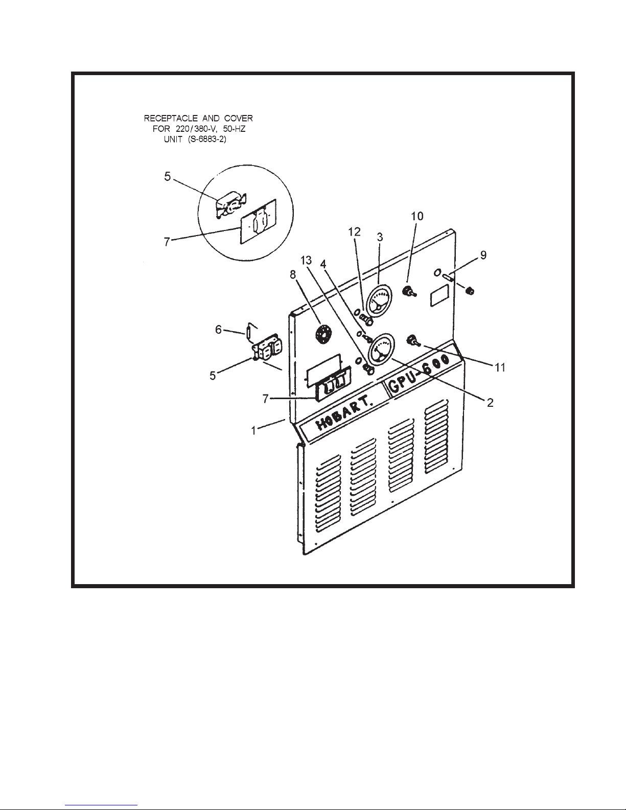
1. Front Panel 8. R13 Start Level Control
2. M1 DC Ammeter 9. F1 Fuse
3. M2 DC Voltmeter 10. S1 Input On-Off Switch
4. DS2 Overload Light 11. S2 Output On-Off Switch
5. 115 VAC Receptacle 12.Input Power Light (amber)
6. MOV Surge Suppressor 13. Output Contactor Light (green)
7. 115 VAC Weather Cover
Front Panel Assembly, GPU-600
April 10/89 Revised 2-1
Figure 4
Page 7
Page 28

OM-2010
The main transformer of the 208/230/460-V power supply
provide the 115-V AC for the auxiliary power receptacle and fan motor. The main transformer has a
center tapped coil on each phase that provides six sensing or synchronizing voltage signals to the
solid state printed circuit control board
The main transformer for the 220/380-V power supply
winding for its auxiliary power receptacle and a 110-V AC winding for the fan motor. Be certain to follow the changeover diagram for both the main transformer and the control transformer
the input voltage you have available.
CAUTION: IMPROPER CONNECTIONS WILL CAUSE DAMAGE. CONTACT FACTORY IF YOUR
EQUIPMENT SPECIFICATION INFORMATION AND/OR VOLTAGE CHANGEOVER DIAGRAM
DOES NOT AGREE WITH YOUR RATED 3 PHASE INPUT VOLTAGE.
C. Control Transformer (10, Fig. 3)
The small control transformer located on the rear of the inside baffle
vides 115 V AC to the K1
(11, Fig. 4)
former. This transformer does not provide the 9A, 115 V AC auxiliary power.
input contactor switch via the half amp F8 contactor fuse
(14, Fig. 3)
(13, Fig. 3).
input contactor coil, input contactor light A
(Spec 6683-1 or 6883A-1)
(Spec 6683-2 or 6883A -2)
(3, Fig. 3)
or lifting eye plate pro-
(20, Fig. 3)
has a winding to
has a 220-V AC
(10, Fig. 3)
(12, Fig. 4),
on the control trans-
and S1
WARNING: ELECTRIC SHOCK CAN KILL! DISCONNECT INPUT POWER AT
SOURCE TO REMOVE VOLTAGE TO CONTROL TRANSFORMER AND INPUT
FUSES AND CONTACTOR.
for
D. Auxiliary Power Circuitry
The 115 V AC single phase auxiliary power receptacle
mary input voltage. It is protected by the F1 fuse
typically, 15 Amperes. The auxiliary power circuitry is turned off whenever the primary contactor is
open or off. The auxiliary power winding is typically located on the middle leg
transformer. It provides power to the duplex 115 V AC receptacle
A “MOV” voltage surge suppressor, RV
nals to reduce voltage surge problems to the load equipment and the power source.
E. Output Contactor Circuitry
Output contactor K2
Placing this switch momentarily in the UP (spring-loaded) position turns the output contactor ON, and
placing it in the DOWN position turns the output contactor OFF.
The positive output lead is to be connected to the positive output terminal of the K2 contactor. The
negative output lead is to be connected to the negative bus bar
capacitor bank
to allow for the output cable assembly to pass out either side.
(9, Fig. 3)
(4, Fig. 3)
is operated by the output contactor ON-OFF switch S2
. A small notch has been made in the bottom of the right and left side panels
(6, Fig. 4),
(5, Fig. 4)
(9, Fig. 4)
is installed across the 115 V AC receptacle termi-
has the same frequency as the pri-
located on the power supply front panel,
(5, Fig. 4)
(B phase)
and to the fan motor.
of the main
(11, Fig. 4).
(5, Fig. 3)
of the C15-C17 output filter
2-1 April 10/89 Revised
Page 8
Page 29

F. Output Filter Circuitry
OM-2010
The DC output voltage is smoothed
carrying the output current to the load and the ripple current to the C15, C16, C17 ripple bypass ca-
3)
pacitors
vide both a preload to the SCR devices
discharging the filter capacitors whenever the power supply is turned off.
CAUTION: CAPACITOR CHARGE CAN INJURE. BE SURE CAPACITORS ARE DISCHARGED
BEFORE TOUCHING.
The CR7 flyback diode
protect the main SCR rectifier assembly from damaging reverse voltage spikes.
G. Front Panel Control Components (See Fig. 4)
(1) Output Meter
(4, Fig. 3)
The power supply is typically supplied with a 0 to 2000 Amp scale DC ammeter M1
which measures the millivolt drop across the R11 meter shunt
scale calibration. The scale range is so much more than the rated output because the R13 starting current potentiometer
a maximum of 2000 amperes. The M2 output voltmeter
age across the main filter capacitors.
The scale typically has a 50 V DC maximum reading. It should be emphasized that the R12 control feedback shunt
ter control integrity.
in parallel with the load terminals. The R2, R3, R4 bypass resistors
(6, Fig. 5)
(21, Fig. 3)
(filtered)
by an L-C filter made up of L1 iron core reactor
(6, Fig. 3)
(2, Fig. 5)
acts to facilitate discharge of the output filter circuitry as well as to
and a safety discharge circuit for quickly
(21, Fig. 4)
(20, Fig. 3)
(8, Fig. 4)
can select any initial or starting current from 250 amperes to
(16, Fig. 4)
is not to be used for the meter shunt. This separation provides bet-
that corresponds to the
measures the DC output volt-
(7, Fig.
pro-
(2) Input Contactor Switch with Light
The S1 input contactor switch
plied by the control transformer via the F8 fuse. The amber input contactor light
whenever voltage is applied to the input contactor coil. The input contactor applies the rated input
voltage to main changeover board
(10, Fig. 4)
(16, Fig. 3).
controls the 115 V AC contactor pickup voltage sup-
(12, Fig. 4)
WARNING: ELECTRIC SHOCK CAN KILL! DISCONNECT THE INPUT POWER
FROM THE POWER SUPPLY BEFORE TOUCHING INTERNAL PARTS. THE INPUT CONTACTOR DOES NOT REMOVE ALL INPUT POWER FROM THE
UNIT. BE SURE ALL CAPACITORS HAVE DISCHARGED BEFORE TOUCHING
THE COMPONENTS.
(3) Output Contactor Switch and Light
The S2 output contactor close on-off switch
close mode, a middle position for “on” mode, and a bottom position for the “off” mode. The green
output contactor “on” light
(13, Fig. 4)
(11, Fig. 4)
glows for all the positions except “off”.
has a spring loaded up position for the
glows
April 10/89 Revised 2-1
Page 9
Page 30

OM-2010
(4) Overload Trip Light (4, Fig. 4)
The overload trip light glows whenever the solid state printed circuit board turns off the power supply output due to output voltage exceeding 31.5 V DC, output current surge exceeding 2200-A
DC.
H.Main SCR Heat Sink Assembly (See Fig. 5)
The main SCR heat sink assembly is mounted on the front of the rear panel. It surrounds the 115 V
AC cooling fan assembly for optimum cooling efficiency. The SCR heat sink
formed aluminum heat sink with 6 “hockey puck” silicon controlled rectifiers held by 6 insulated compression spring assemblies held against it by 6 U-shaped aluminum heat sinks for the “hockey puck”
device cooling, two snubber pc board assemblies for SCR gate signal control and protection
the associated insulators, thermostats and hardware.
5),
(2, Fig. 5)
consists of a
(1, Fig.
The solid state printed circuit board
quenced turn on signal to the silicon controlled rectifiers that must conduct to provide the desired output. If the output voltage is too high or if the output current is above the limit set by controls such as
the R13 starting potentiometer, the “pcb” control delays the SCR turn-on signal to allow less SCR device conduction time for a correspondly lower output. Conversely, if the output voltage is too low, the
SCR turn-on signal is delivered earlier in the possible conduction time for each SCR thereby allowing
more power to be supplied because of the longer conduction time. Proper operation of the SCR devices requires phase sequence and presence of all 6 voltage sensing signals, proper phase sequence and presence of the output voltage to the SCR devices and the proper magnitude and
sequence of the SCR turn-on signal to the SCR gate leads.
J. Solid State Printed Circuit Control Board (13, Fig. 3)
The printed circuit board is located in a steel box behind the front access door on the power supply
right side panel
following functions:
(1) Electronic Overvoltage/Overload Trip Circuit
The “pc board” trips the power supply off and turns on DS-2 red overload trip light
the front panel if more than 31.5 V DC or 2200 A overload exists. To reset, correct the cause of
the condition and then turn the input switch off and back on.
(2) Electronically Controlled Current Limit
The starting current or output surge current is selected by adjusting R13 starting current control
(8, Fig. 4)
(2, Fig. 3).
on the front panel from the minimum 250 A DC to the maximum 2000 A DC.
This large printed circuit board is the “brains” or electronic control for the
(13, Fig. 3)
described later provides a properly timed and se-
(4, Fig. 4)
on
CAUTION: EXCESS STARTING CURRENT MAY CAUSE DAMAGE TO LOAD, BLOW FUSES OR
DAMAGE POWER SUPPLY. CONTACT FACTORY IF YOU REQUIRE A CURRENT LIMIT LOWER
THAN THE 250 A DC STANDARD MINIMUM LIMIT.
(3) Regulated DC Output Voltage
The voltage value is continuously compared to the actual output. If adequate input voltage exists,
deviation from the desired voltage output is corrected by the change in SCR conduction time set
by the printed circuit board firing pulse output. This corrective action is done quickly because the
control is done electronically with only limited stored energy in the circuitry. Typical response time
is about 25 milliseconds.
2-1 April 10/89 Revised
Page 10
Page 31

(4) Thermal Overload Trip
The printed circuit board turns off the SCR firing or gate pulses and turns on the trip light when S5
overload thermostat
(3, Fig. 5)
S5 thermostat cools enough to automatically reset
opens. The power supply can not produce any DC output until the
(close).
OM-2010
1. Surge Suppressor (2) 4. Metering Shunt, R12
2. SCR Heat Sink Assembly 5. Heat Sink Insulator (2)
3. Overload Thermostat, S5 6. Flyback Diode, CR7
April 10/89 Revised 2-1
SCR Heat Sink Assembly
Figure 5
Page 11
Page 32

OM-2010
This page intentionally left blank
2-1 April 10/89 Revised
Page 12
Page 33

CHAPTER 2. DESCRIPTION AND
OPERATION
SECTION 2. OPERATION
1. General
This section contains information for safe and efficient operation of the equipment. Operating instructions
are presented in step-by-step sequence of procedures to be followed in supplying 28 V DC to an aircraft
or similar load.
WARNING: ELECTRIC SHOCK AND FIRE CAN KILL! READ AND UNDERSTAND ALL OPERATING INSTRUCTIONS BEFORE ATTEMPTING TO OPERATE THE EQUIPMENT. OPERATION ATTEMPTS BY UNTRAINED
PERSONNEL CAN ENDANGER PEOPLE, THIS EQUIPMENT, AND THE LOAD.
DO NOT ATTEMPT TO OPERATE THE EQUIPMENT FOR USES NOT APPROVED BY THE MANUFACTURER, OR AT INPUT AND OUTPUT RATINGS
NOT LISTED IN THE SPECIFICATION TABLE LOCATED IN 2-1, FIGURE 2.
OM-2010
The repeated opening of input fuses or repeated functioning of the overload trip circuitry indicates a misapplication, a faulty main component, or an improper connection or load. Correct the problem by following
the instructions in Chapter 3 before attempting to operate the power supply. Be certain that an input disconnect means is readily accessible between the power input source and this DC power supply. You may
need to quickly isolate the DC power source from all power during an emergency, fire, or equipment malfunction.
2. Preparation for Operation
A. Verify input power is disconnected at source.
B. Verify that the supply input connections agree with the input voltage available by comparison to the
voltage changeover diagram.
C. Connect your output cable between your load and the proper connection points in the DC power
supply.
D. When all covers or panels are in place, turn on the source of input power.
E. Set R13 start level control knob
(9, Fig. 1)
to the output surge limit required for your load.
April 10/89 Revised 2-2
Page 1
Page 34

OM-2010
3. Operation Procedure
A. Input Control Functions
(1) Turn on S1 input contactor switch
(2) Verify that only the amber input power light
requiring service.
B. Output Control Functions
(1) Hold the S2 output contactor switch
green output contactor light
(2) Release S2 switch to the middle “ON” position.
(3) Verify that M1 DC ammeter
(4) The DC power supply should continue to deliver power until the S2 switch is placed in the down
“OFF” position or one of the other control means functions to turn the unit “OFF”.
C. Voltmeter
(1) Verify on the M2 DC voltmeter
power supply, disconnect your load, and refer to Service, Chapter 3 for instructions.
D. Output Current Limit
(1) If the DC ammeter continuously reads more than 600 A DC after start-up, immediately turn R13
current limit control
may prevent automatic overload trip out or blowing of fuses or tripping of circuit breakers at the
source of input power.
(9, Fig. 1)
(10, Fig. 1)
down to continuous operation current point, normally 600 A DC. This
(4, Fig. 1).
(5, Fig. 1)
(6, Fig. 1)
(7, Fig. 1)
(4, Fig. 1)
to glow.
does not read an excessive amperage. Release S2 switch.
in the up “CLOSE” position long enough for the
that the DC output voltage level is correct. If not, turn off
glows. If the light glows, no problem exists
(2) If R13 has no effect or if the output current cannot be decreased to about 250 A DC at the R13
minimum position, a faulty SCR device or control circuit malfunction is indicated requiring power supply repair. Refer to Chapter 3 for service instructions.
2-2 April 10/89 Revised
Page 2
Page 35

OM-2010
1. Front Panel 8. Red Overload Trip Light, DS2
2. Control Fuse, F1 (15A) 9. Start Current Potentiometer, R13
3. Input ON-OFF switch, S1 10. Green Output Contactor Light, DS3
4. Output Contactor Switch, S2 11. Auxiliary Power Receptacle, 115V-AC
5. Ammeter, 0-2000 A DC, M1 12. Auxiliary Power Receptacle Cover
6. Voltmeter, 0-50V DC, M2 13. Rating and Specification Nameplate
7. Amber Input Power Light, DS1 14. Caster Wheel Brake
April 10/89 Revised 2-2
Controls and Instruments
Figure 1
Page 3
Page 36

OM-2010
This page intentionally left blank.
2-2 April 10/89 Revised
Page 4
Page 37

CHAPTER 3. SERVICING
SECTION 1. MAINTENANCE
1. General
To be certain the DC power supply set is ready for operation at all times, it must be inspected and maintained systematically so that defects may be discovered and corrected before they result in serious damage or failure of the equipment. Defects discovered during operation of the unit should be noted for
correction to be made as soon as operation has ceased.
WARNING: HIGH VOLTAGE - ELECTRIC SHOCK CAN KILL! BE CERTAIN
THE INPUT POWER SOURCE IS TURNED OFF BEFORE PROCEEDING WITH
ANY INSPECTION OR MAINTENANCE OPERATION WHICH COULD BRING
PERSONNEL IN CONTACT WITH HIGH VOLTAGE OR REVOLVING EQUIPMENT. STOP OPERATION IMMEDIATELY IF A POSSIBLE DANGEROUS
FAULT IS DISCOVERED. THE FRONT PANEL INPUT CONTACTOR SWITCH
DOES NOT REMOVE INPUT POWER FROM ALL COMPONENTS. BE SURE
CAPACITORS ARE DISCHARGED BEFORE YOU TOUCH.
OM-2010
The power supply is designed to be as maintenance free as possible, therefore, there are few inspection
and maintenance requirements.
2. Inspection
A periodic inspection schedule should be established and maintained. A suggested inspection/check
schedule is provided in Section 3-2, Figure 1; however, it may be changed as required to meet varying operating conditions and environment. See Section 2, Inspection/Check for inspection and check procedures to be used in conjunction with Section 3-2, Figure 1 schedule.
3. Lubrication
The subject of lubrication is mentioned here mostly to inform maintenance personnel that it has not been
overlooked. Except for sleeve bearings in the fan motor, no lubrication is required. Refer to Section 1-2,
Para. F for fan motor lubrication instructions.
NOTE: The fan motor is designed for 10,000 hours between bearing lubrications. Relubrication for even
longer life at 10,000 hours requires fan motor removal and dissassembly, possible but not normally
recommended.
A good silicone spray lubricant is recommended for hinges if exposure to weather should make them difficult to operate.
April 10/89 Revised 3-1
Page 1
Page 38

OM-2010
4. Parts Replacement
A. Minor electrical components
(1) Lamps and fuses are mortality type items which require simple periodic replacement.
(2) Switches, meters, contactors and fan motor in the power supply fall into the category of parts
which can be expected to fail at infrequent, irregular intervals. Instructions for repair and replacement of these parts are obvious. Be certain the input power is turned off. Obtain the replacement
part specified in the parts list. Replace the part by substituting the new part for the old taking care
not to mix up the leads. See Sections 2 and 3.
(3) The user-supplied disconnecting means must be of proper capacity for the rated input voltage.
See the rating for your input as listed for your use in 1-2, Figure 1, recommended wire size table.
Be certain your specification number is designed for your input voltage. No visible inspection is
possible, except for the marked rating if the input power source is off. The use of the wrong input
voltage could be the cause for equipment damage.
B. Major Electrical Components
(1) Major electrical components such as the power transformer, filter choke, and SCR devices on
the SCR heat sink assembly should be replaced or repaired at an overhaul type facility.
(2) The firing circuit board can be easily replaced as a “plug-in” assembly. Minor calibration adjust-
ment may be required for optimum performance. It is recommended, however, that this adjustment be made only by factory authorized personnel.
(3) The flyback rectifier diode located on the main SCR heat sink assembly rarely fails from normal use. If replacement is ever required, be sure to connect the replacement exactly as the original after torque wrench tightening the nut to the stud at 4.2 to 5.2 foot pounds
(5.70 to 7.05
newton meters).
(4) SCR device replacement requires extreme care, special tools, and the exact replacement part
and technique for optimum performance. The replacement of the SCR should be done at the factory or an authorized repair facility. A replacement SCR bridge subassembly can be obtained
from the factory which would allow the customer to install so long as he was certain to exactly replace all leads and components in the same position with the same hardware. This task would
still require considerable care and time.
3-1 April 10/89 Revised
Page 2
Page 39

Section 2. INSPECTION CHECK AND REPAIR
1. General
This section describes inspections and checks to be performed in conjunction with Inspection/Check
Schedule, Figure 1. For satisfactory service, keep the power supply clean, dry, and well ventilated. At the
prescribed intervals or more often as necessary, disconnect the power supply from the input power
source and wipe and blow out all dirt and other foreign materials from the internal components, including
the fan blades. Air pressure should not exceed 25 ps;
(172 kPA).
2. Exterior Cables and Connections
A. Input and Output Cables
Observe general condition of power input cables and equipment output cables. Inspect for cuts and
abrasions in the insulation which could cause a short circuit. Visually inspect the output cable plug
connector for physical damage and evidence of overheating.
B. Cable Connections
OM-2010
Check all input and output cable connections for tightness and security.
WARNING: HIGH VOLTAGE - ELECTRIC SHOCK CAN KILL! TURN THE
SOURCE OF INPUT POWER OFF WHEN CHECKING THESE CONNECTIONS.
BE CERTAIN CAPACITORS ARE DISCHARGED BEFORE TOUCHING THE
CIRCUITRY.
3. Controls and Instruments
A. Voltmeter, Ammeter and Control Switches
These components can be damaged by abuse, shipping, and type of use. Observe these instruments
at each “start-up” to verify they are operating. If one of the meters is suspected of being inaccurate,
check it against a master, or test instrument. Replace any faulty or intermittently faulty switches immediately.
B. Indicating Lights
(1) Power input and output lights
Life of incandescent bulbs varies with the magnitude of voltage and vibration. Check the lamps
(bulbs)
ter the replacement, the circuitry is defective and should be repaired. If the proper voltage
reaches the base terminals, replace the base; if not correct the wiring fault.
in these lights by substituting a known good replacement lamp. If the lights do not glow af-
April 10/89 Revised 3-2
Page 1
Page 40

OM-2010
(2) Overload trip indicating light
More than 31.5 V DC output or overcurrent trips overload trip light DS2. The light emitting diode
circuit resets when S1 power on switch is cycled off and back on after the cause of the trip has
been removed. The LED light does not fail in normal use. Applying reverse voltage or overvoltage
to it during a test would be a more probable cause for failure, therefore applying a direct test is
not recommended. A bad light does not come on during a trip.
C. Overload Thermostat
The S5 overload thermostat must be closed in order for the DS2 overload light not to be on during
equipment turn-on. If AC power input is disconnected, verify continuity exists between the two S5
terminals with the leads to one of the terminals disconnected. Replace the S5 thermostat if the
wiring terminals on the S5 thermostat are not shorted.
D. Starting Current Limit Potentiometer
If the R13 starting current control has no effect on the output current above 250 A DC, check the
integrity of the R13 potentiometer before replacing the solid state control board. With input power
off and the R13 potentiometer slider terminal disconnected from the wiring, the resistance to the
slider terminal from each end of the potentiometer should change smoothly as the knob is turned.
If not, replace the potentiometer and retest. If retesting shows no change, the printed circuit control board is probably faulty also.
3-2 April 10/89 Revised
Page 2
Page 41

AS DAILY 1 MONTH 3 MONTH 6 MONTH
REQ'D 8 HRS. 200 HRS. 600 HRS. 1200 HRS.
* EXTERIOR CABLES
Inspect equipment output
cables X
Inspect AC input cables X
Check cable connections
(internal) X
* CONTROLS AND
INSTRUMENTS
Check voltmeter functioning X
Check ammeter functioning X
Check fan thermostat
operation X
Check indicating lights X
Check starting current
limit functioning X
Check overload thermostat X
Check printed circuit
control board X
Check all output contactor
contacts X
Check power input contactor
contacts X
Check voltmeter & ammeter
accuracy X
Check all wiring and
connections X
Inspect and clean general
(light duty) X
Inspect and clean general
(severe duty) X
OM-2010
* Suspicious performance occurrence overrides timetable given.
April 10/89 Revised 3-2
Inspection/Check Schedule
Figure 1
Page 3
Page 42

OM-2010
E. Contactors
(1) Output Contactor, K2
(2) Input Contactor, K1
The output contactor has contacts that can be visually inspected whenever the input power is removed from the power supply. If the contacts are badly burned the contactor should be replaced
as soon as possible. Slightly pitted and burned contacts can be cleaned up with a commercial
contact cleaner and very fine grained emery cloth or equivalent. If application of 28 V DC to the
coil of the K2 contactor does not make the normally open contacts close completely or the normally open contacts open completely, the contactor should be replaced if the contact mechanism
can’t be mechanically adjusted for proper operation.
If input power has been turned off at the source of power, the K1 input contactor contacts can be
visually inspected by removing the two screws holding the contact cover in place. If the contacts
are badly eroded, burned, or stuck, the replacement contacts and spring for each pole can be ordered with the number given in the applicable replacement parts list. If the contactor with DS1
light on has failed to pick up before the inspection, and no mechanical obstruction has been
found, the contactor should be replaced or repaired with the replacement coil and contacts specified in the parts list. Many customers prefer to replace the whole contactor, especially for the condition showing bad coil and contacts. If DS1 light is good but does not glow and the F8 fuse
checks good, the problem is in the control transformer circuit.
F. Control Transformer
The control transformer is located on the rear of the lifting baffle. The F8 fuse
mounted on top of the control transformer. The voltage input connection on the control transformer
must also be changed whenever the input voltage changes.
Not changing the input connection when going from a lower to higher input voltage will result in a
burned out control transformer. The same result occurs if a larger than 1/2 ampere fuse is substituted
for F8, especially if the input contactor is faulty. The only sure way for checking the control transformer to verify what the input voltage and output voltages are. If there is no proper output with proper
input voltage, replace the control transformer.
(.5A)
is normally
4. Major Components Check and Repair
A. Main Power Transformer
No replacement parts are available for the main transformer. The replacment power transformer part
number for your specification number is given in the replacement parts list in Chapter 4. This part and
most of the major component parts can best be replaced at the factory or a factory authorized repair
facility. However, replacement can be done by the customer if he exercises care to reconnect everything to the same points and in the same manner as the original part.
WARNING: HIGH VOLTAGE - ELECTRIC SHOCK CAN KILL! TURN THE
SOURCE OF INPUT POWER OFF WHEN CHECKING THESE CONNECTIONS.
BE CERTAIN CAPACITORS ARE DISCHARGED BEFORE TOUCHING THE
CIRCUITRY.
3-2 April 10/89 Revised
Page 4
Page 43

OM-2010
Normally, a visual inspection will not find a transformer problem until the failure is very severe. The
typical inspection is a voltage measurement test for rated primary input voltage and for 6 rated and
balanced line to neutral AC voltages at the transformer secondary terminals. Refer to the applicable
voltage changeover diagram for the input voltage test points and to the applicable connection diagram for the transformer secondary test connection points. The normal transformer line to neutral secondary voltage is approximately 33 V AC with no output amperage. Line to line voltage on the
secondary is 66 V. If the fuses blow or circuit breakers trip immediately in the user-supplied disconnect switch and no evidence of lead shorting exists at the input contactor, or the primary connection
terminal board, both the main transformer and the SCR control assembly are suspect. Open the input
disconnect switch external to the power supply, label all the transformer leads going to the six Ushaped SCR heat sinks before disconnecting and insulating the leads. Also disconnect the flyback diode “pigtail” lead 105 and L1 filter lead 104. These connection changes enables you to check the
transformer only.
After verifying that input power can be turned on from the power source safely, turn the rated input
power on. After the S1 input contactor switch is closed carefully measure the output line to neutral
voltages if the primary input is still on. If the input power source voltage trips out when the unit is
turned on, the main transformer has probably failed. To verify failure, disconnect the input power at
the power source and then remove the copper links
(jumpers)
on the main voltage changeover board.
If turning the primary input voltage on, after input breakers at the power source have been reset, results in no high input current, the main transformer is bad.
If the problem still exists, the problem is not in the main transformer. Check the main connection terminal board for faulty connections and check the control transformer and input contactor. Go to 4.B if no
problem existed with all the SCR devices disconnected.
B. Silicon Controlled Rectifier Assembly and Flyback Diode
(1) Visual
No visual failure capability is possible with the SCR assembly, except for faulty leads or misconnections which we assume have been found and corrected. The input power at the power source
should be turned off at the start of the SCR check out.
(2) Voltohmmeter
To check with voltohmmeter, set the meter to the RX1 scale and check for a shorted SCR by
measuring between each of the 6 U-shaped heat sink and the main heat sink. No reading should
be possible with either polarity of lead connection. The flyback diode should read 4 to 14 ohms in
one direction and a very high reading with the leads from the voltohmmeter reversed. If the flyback diode is shorted,
Replacement Parts)
7.05 newton meters).
(a rare occurrence)
replace it with the same type of device
taking care to torque the nut to the stud with 4.2 to 5.2 foot. pounds
If the SCR bridge has one or more SCR devices showing a short circuit or
low ohmmeter reading, it is recommended that the GPU-600 power supply be sent to the factory
or an authorized repair station for repair. A replacement SCR bridge subassembly can be obtained from the factory which would allow the customer to replace the faulty SCR bridge assembly without special tools and techniques. He must still be careful to exactly replace all the
mounted subassemblies and the connection leads exactly as they were on the faulty heat sink assembly. Special tools, parts, and techniques are required to replace single SCR devices on the
heat sink assembly.
If the SCR heat sink and diode assembly checks good with the voltohmmeter, the components
could still be failing due to voltage breakdown at voltages above that of the voltohmmeter. Go to
4. B.
(3)
Voltage test.
(see Chapter 4 -
(5.7 to
April 10/89 Revised 3-2
Page 5
Page 44

OM-2010
(3) Voltage Test for SCR Assembly
With input power turned off, reconnect one SCR device at a time and apply power until the input
power is interrupted by a fault condition or all the SCR devices are connected. The last SCR device to be connected before interruption is faulty. If no fault occurred, the SCR’s are all good. The
input power should be turned off and the flyback diode mounted on the SCR heat sink should
have the pigtail lead reconnected to lead 105. If reapplication of power causes a trip-out, replace
the faulty flyback diode. The diode nut must be torqued to 4.2 to 5.2 foot pounds
ton-meters).
C. Filter Choke and Capacitor Voltage Test
Reconnect L1 Filter Choke lead 104 to the proper point as shown in the connection diagram. Visually
check the C15, C16, and C17 capacitors for indication of a faulty connection which could cause the
problem.
If no failure occurred, go to 4. C. after turning input power off.
WARNING: CAPACITOR CHARGE CAN INJURE! BE SURE CAPACITORS
ARE DISCHARGED BEFORE TOUCHING OUTPUT CIRCUITRY. STAY CLEAR
OF CAPACITORS DURING TESTING. THEY CAN BURST.
(5.7 to 7.05 new-
Reapply input voltage. If trip out occurs, either the C15, C16, or C17 capacitors, or the connecting wiring between them, are shorted. Disconnect the input voltage at once, allow the capacitors time to discharge, and disconnect the positive and negative wiring from the capacitor assembly. Replace any
shorted or bad capacitors
necting wiring. If the problem is found to be the L1 filter choke breaking down to ground, another
grounded component must be present on the
to occur. Check for the second grounded component also.
D. Printed Circuit Control Board
The best, most quick way to verify condition of a suspected printed circuit board is to exchange it for a
known good one. This plug-in substitution method using a known good board also allows the equipment to go back on line immediately while the faulty board is sent back to the factory for repair or replacement. Field repair is not recommended.
Before assuming the board is faulty when you have no spare board perform the following checks:
(a) Check for blown fuses F2 thru F7 and replace bad ones for a retest under power. If unit now
works, the problem may be solved or an intermittently present one. Keep record of which fuse
blew for later assistance.
(b) Check for broken or shorted leads on or to plugs J1, J2, and J3 plugged into the printed circuit
control board. Use the applicable schematic and connection diagrams for instructions and lead locations.
(c) Check snubber printed circuit boards on the right side of the SCR heatsink assembly for
shorted or broken leads and for signs of overheating.
(having case deformation caused by high shorting amperage),
(+)
side for the high current output to cause the trip out
or bad con-
(d) Check the SCR gate leads for breaks or short circuits and correct any problems found before
retesting.
3-2 April 10/89 Revised
Page 6
Page 45

OM-2010
(e) If the reason the pc control board is being checked, and no substitute board exists, is insufficiency of output voltage with proper AC secondary voltage at the main transformer, check for
proper pc board voltages
(See 3-3),
if no oscilloscope is available. If the readings are good, the
problem may be one or more open SCR devices. The best test equipment is an oscilloscope but
the use of a crude SCR tester with the input power off can verify open SCR devices but not hard
to fire ones. One type of SCR turn-on tester is a battery power circuit tester with a light bulb in series with the battery and two leads. With input power off, the positive lead is connected to the anode of the SCR under test and the negative lead is connected to the cathode of the same SCR
device. The light should stay off until the gate lead of the same SCR has the positive voltage applied to it. If the light turns on and remains on after the gate lead voltage is removed so long as
the anode and cathode leads stay connected, the SCR is probably good. If the SCR stops conducting as soon as the gate lead is removed, an anode to cathode open or very hard to drive
faulty SCR is probable. If any SCR devices are found to be faulty, the printed circuit board may
not be faulty unless the voltages in 3.3 of the pc board test aren’t achievable. Then both components may be faulty.
April 10/89 Revised 3-2
Page 7
Page 46

OM-2010
This page intentionally left blank
3-2 April 10/89 Revised
Page 8
Page 47

SECTION 3. CALIBRATION AND TEST OF PC CONTROL BOARD
1. General
This section describes the test points, test values, and adjustment locations for testing and adjusting
the printed circuit control board which is the “brains” of the GPU-600 DC power supply. As a minimum
the following equipment and tools are required.
A. High impedance, high accuracy DC voltmeter;
B. Small, standard blade screwdriver;
C. Small, insulated clip leads;
D. A resistance load bank or equivalent that can safely dissipate 2200 ADC at 20-V DC if the
overcurrent trip point is to be checked or adjusted.
Faulty control boards should be returned to the manufacturer for repair.
2. Printed Circuit Board Test Values and Adjustments
OM-2010
A. Refer to Figure 1 for the location of test points and adjustment potentiometers for possible field
adjustment.
B. Test point values and comments about the measurements and testing conditions are tabulated
in Figure 2.
WARNING: ELECTRIC SHOCK AND ARCS CAN KILL OR INJURE! USE ACCESS DOORS TO INSPECT, OR TEST THE PRINTED CIRCUIT CONTROL BOARD WHILE THE EQUIPMENT IS RUNNING.
THE VOLTAGES ON THE PRINTED CIRCUIT BOARD ARE SAFE; HOWEVER, REMOVING THE RIGHT
SIDE PANEL EXPOSES PEOPLE TO DANGEROUS VOLTAGES.
C. Test and Calibration Procedure
Follow Figures 1 and 2 to verify that the PC board is functioning to the standard. If the voltage
readings to the PC board common are not within specification, attempt to correct the reading by
adjusting the applicable control. Be certain the operating conditions are exactly as stated in Figure 2. If the board does not adjust and the leads, fuses
board are good and proper, the PC control board is faulty. Replace it with a known good board after the input power has been turned off. The PC board is held in place by six
screws. After unplugging the three polarized connection plugs, remove the screws and keep for
the new board. Reverse the procedure when the new PC board is mounted in the exact orientation of the old board. Recheck the voltages. In some cases a minor adjustment may be required
for optimum calibration. If the same magnitude of error and lack of adjustment control is encountered, it is possible that the control board is not at fault.
Consideration should be given to returning the GPU-600 DC power supply to the factory or an
authorized repair facility if your recheck of the GPU-600 does not find the cause of the difficulty.
Field repair of the PC control board is not recommended.
(F2-F7)
, and connectors to the PC control
(6)
self tapping
April 10/89 Revised 3-3
Page 1
Page 48

OM-2010
CAUTION: IMPROPER TEST EQUIPMENT CAN DAMAGE! USE ONLY RECOMMENDED TEST
EQUIPMENT AND TOOLS. NEVER APPLY TEST VOLTAGE DIRECTLY TO COMPONENTS ON
THE BOARD. THIS SOLID STATE CONTROL USES LOW CURRENT DEVICES THAT QUICKLY
BURN OUT IF A LOW IMPEDANCE VOLTAGE SOURCE IS APPLIED DIRECTLY TO THE COMPONENT. THE DEVICE MAY NOT FAIL UNTIL LATER FROM THE TEST.
3-3 April 10/89 Revised
Page 2
Page 49

OM-2010
1. TP1 SCR Gate Pulse from R10 13 TP14 Null at 0 A DC TP, (R38) *
Adjust. 14. R60 Overload Limit, (TP20)
2. TP2 SCR Gate Pulse from R9 15.R109 28 V DC Output Cal., (TP13)
Adjust.
3. R9 Balance Adjust. Phase 2, 16. R101 5 V Ref Volt Adjust., (TP19)
(TP2) 17. R102 Voltage Slope Adjust.,(TP17)
4. R10 Balance Adjust. Phase 3, 18. TP19 Reference Volt Test Point,
(TP1) (R101)
5. TP8 Balanced SCR Gate Pulse, 19. TP17 Voltage Slope Test Point,
Phase 1 (R102)
6. R38 No Load Amp OFF Set Null, 20. TP15 Common, PC Board Volts
(TP14)* 21. TPF SCR Gate Pulse Timer
7. R37 Overvoltage Trip Point 22. TPE Gate Timer Output, Phase 2
8. TP3 PC Board Common 23. TPD Gate Timer Output, Phase 3
9. TP4 + 9.1 V DC Timer Voltage 24. TP13 Actual Output Volts
10. TP5 + 15 V Regulated Voltage (28.5 or 14.25)
11. TP6 - 15 V Regulated Voltage 25. TP20 Overload Limit (R60) Adjust
12. TP7 + 24 V Nonregulated
Voltage 26. TPL Overload Trip Summing Point
* Note: TP14 provides amplified load Amp reading for comparison with overload limit (TP20) and starting
amperage limit (TP21) set by R13 control on front panel.
Printed Circuit Control Board Test Points
Figure 1
April 10/89 Revised 3-3
Page 3
Page 50

OM-2010
3-3 April 10/89 Revised
Page 4
Test Value and Comment Tabulation
(For PC Board No. 180294A)
Figure 2 (Sht. 1 of 2)
Page 51

OM-2010
April 10/89 Revised 3-3
Test Value and Comment Tabulation
(For PC Board No. 180294)
Figure 2 (Sht. 2 of 2)
Page 5
Page 52

OM-2010
This page intentionally left blank
3-3 April 10/89 Revised
Page 6
Page 53

SECTION 4. TROUBLESHOOTING
1. General
A. Troubleshooting is an orderly process of checking and eliminating possible causes of trouble until the
exact cause of a trouble is found. As a rule, the best place to start looking for the cause of a trouble in a
circuit is at the source of power. Continue testing and checking the circuit, step-by-step, in an orderly man-
ner, until the cause of trouble is located. See applicable connection diagrams and schematic diagrams.
Do not overlook the obvious. Loose connections are the primary cause of malfunctions, both internal and
external to the machine. Do not overlook bad grounds, wrong settings, or worn out contactors.
Test points are identified on schematic diagrams listed in Chapter 5. P.C. Board test points are identified
and test point values are given in Section 3-3, Figures 1 and 2. The minimum equipment needed to trou-
bleshoot this machine is a simple voltohmmeter. An oscilloscope is the best device to find and correct diffi-
cult problems.
B. This section provides information useful in diagnosing and correcting certain troubles which cause un-
satisfactory operation or failure of the equipment.
C. Minor troubles may be remedied by the operator; however, major repairs must be undertaken by expe-
rienced mechanics and electricians only. Replacement of SCR devices are to be performed at the factory
or an authorized service center.
OM-2010
2. Troubleshooting (See Figure 1)
A. Description The troubleshooting chart lists information under three headings:
(1) Trouble, symptom, and condition
(2) Probable cause
(3) Test, check, and remedy
B. Use of the Troubleshooting Chart
The troubleshooting chart is designed to provide maintenance and repair personnel with a time-saving
guide for locating the source of a trouble.
(1) Terminal points
ply at several locations, provide easily accessible and identifiable test points for checking circuits and
electrical components.
(2) Test points are located throughout the circuitry in such a manner that input and output power may
be used for test purposes. Because of these test points and their location, a complete check of circuitry may be completed very quickly. Therefore, “probable causes” and “remedies” are listed in a
step-by-step sequence which will insure power for testing in all instances where input or output power
may be used with proper safety practices, test equipment, and training experience.
(3) Printed circuit board output troubles should be pinpointed only to determine if the problem is a
board calibration problem or a PC board failure problem. Failure of PC board requires replacement of
the board. Field repair attempts are not recommended. See 3-3 for calibration instructions.
(Ref. applicable schematic and connection diagrams),
installed on the power sup-
April 10/89 Revised 3-4
Page 1
Page 54

OM-2010
(4) Always check circuit fuses, circuit breakers and the position of switches first in troubleshooting.
The incorrect positioning of a switch may cause a condition which could be misinterpreted as a fault.
(5) Electrical component symbols, which are used on schematic diagrams, and their legends to iden-
tify components, may be used in the troubleshooting chart
help maintenance personnel identify parts on the schematic diagrams.
(in parentheses after the item name)
3. Equipment for Troubleshooting
A good quality multi-scale voltohmmeter is the only instrument required for troubleshooting. However, for
checking certain erratic, intermittent, or phase relationship problems, a good oscilloscope is strongly recommended.
4. Safety
WARNING: HIGH VOLTAGE - ELECTRIC SHOCK AND FIRE CAN KILL! EXERCISE EXTREME CARE TO AVOID CONTACT WITH HIGH VOLTAGE LEADS
AND COMPONENTS WHICH COULD CAUSE SERIOUS SHOCK AND INJURY
IF TOUCHED WHEN TROUBLESHOOTING OR OPERATING THE EQUIPMENT.
STAY CLEAR OF MOVING PARTS. LOCATE EQUIPMENT IN A SAFE ENVIRONMENT. HAVE PROPER SAFETY EQUIPMENT AVAILABLE. DO NOT ATTEMPT OPERATION OR REPAIR WITHOUT ADEQUATE TRAINING.
to
5. Voltages of Interest
A. Across the secondary on all 3 phases - 66 VAC + 10% *
B. To secondary coil center tap on all phases - 33 VAC
* The
+ 10% refers to the possibility of input voltage being out of balance or not at the nominal
value.
C. Across the 115 VAC receptacle - 115 VAC
D. Between X1 and X3 on Fuse Block - 37 VAC
E. Test Point Values for PC board
A control board malfunction will probably result in
(c)
full load current, or
values between a few selected test points shown in Section 3-3, Figure 1.
NOTE: All potentiometer operating values are preset at the factory, and normally should not have to be
reset in the field. If a need arises that would indicate the need for field adjustments, please contact the
factory at Troy, Ohio. Typically, R109, (28 V output) is the only factory set value which the customer’s
use might dictate a minor change in setting. For example, long cables might need a few tenths of a volt
higher set values to compensate for the cable drop.
output voltage too high or too low. See Section 3-3, Figure 2 for nominal test
+ 10% *
+ 10% *
+ 10% *
(a)
a loss of output voltage,
(b)
inability to produce
3-4 April 10/89 Revised
Page 2
Page 55

6. SCR Malfunction Instructions
A. Normal SCR Malfunction Conditions
OM-2010
(1) Blown line fuses as the result of a shorted SCR
ode will also produce this situation. This is a severe malfunction. See 6B.
(2) If one SCR does not turn on
(gate circuit open)],
ripple voltage at the output will increase.
(3) If two SCRs do not turn on, the ripple current will increase and can cause other problems.
sult troubleshooting procedure)
B. Severe SCR Malfunction Conditions
(1) In the case of a severe malfunction, such as a shorted SCR or diode, do not turn on the unit. Dis-
connect the leads from the transformer to the heat sink assembly and check with a VOM for shorted
SCRs or a shorted flyback diode.
(2) To eliminate the possibility of a control malfunction, go inside the unit and check the control circuit
board. See the instructions provided for this test. It is important to run through the tests in the order
they are listed. Note that the SCR devices and flyback diode are still disconnected.
C. SCR tests or checks
(1) If nothing is found defective on the board the next step is to go to the SCRs. First of all an open
gate or an open SCR cannot be checked with a VOM. If an SCR is not firing, the AC ripple current will
increase across the filter capacitors, but no fuses blow. Also, the ripple voltage will increase at the output.
(2) The best way of checking for a SCR device or flyback diode which breaks down into a shorted condition because of inadequate voltage withstand capability is to add one component at a time and then
turn on the input power for a short time. When the faulty component gets connected, excessive input
current will flow.
a very small change will occur at the output which will be difficult to notice. The
[(either it is open or the gate signal is not being received by the SCR
(similar to a shorted diode)
. A shorted flyback di-
(Con-
WARNING: ELECTRIC SHOCK AND FIRE CAN KILL! DO NOT TOUCH ENERGIZED PARTS. DO NOT LEAVE POWER SUPPLY ON LONG ENOUGH TO
OVERHEAT OR FAIL IN THE FAULTY CONDITION.
(3) The best way to check that all SCR devices are firing and conducting correctly is to connect the
probe of an oscilloscope to the heat sink and the isolated neutral of the oscilloscope to the braid of
the flyback diode. The SCR pulses will show as 6 evenly spaced pulses of about the same height. If
one of the pulses appears to be part of a malfunction SCR device circuit, the gate lead for that device
may be disconnected from the applicable suppressor board point. The lead disconnection which does
not affect the trace is the lead for the SCR device and suppressor circuit in question. However, if
every third pulse is low or missing, check the balance adjustments, R9 and R10, before attributing the
problem to faulty components.
April 10/89 Revised 3-4
Page 3
Page 56

OM-2010
TROUBLE, SYMPTOM AND CONDITION
PROBABLE CAUSE
TEST, CHECK, AND/OR REMEDY
MACHINE WILL NOT OPERATE
1. Machine will not start.
Step 1. Input power turned OFF at Remote Disconnect Switch.
Turn power ON at Remote Disconnect Switch.
Step 2. Blown fuse in Remote Disconnect Switch.
Replace blown fuse. If fuse blows frequently, determine
and remedy the cause.
Step 3. Incorrect input power connections at machine.
Check input power connections against appropriate
connection diagram in Chapter 8.
2. Line contactor fails to close.
Step 4. Incorrect power input (frequency and voltage).
Check that voltage and frequency of power input are
proper for this generator unit, according to the rating on
its nameplate.
Step 5. Broken input cable.
Repair cable as necessary.
Step 1. Fuse blown or breaker tripped at input disconnect switch.
Replace fuse or reset circuit breaker. Check for cause if
this malfunction happens frequently.
Step 2. Mechanical obstruction on contactor.
Remove obstruction.
Step 3. Defective line contactor switch.
Replace line contactor switch.
Electrical Troubleshooting Chart
Figure 1 (Sheet 1 of 7)
3-4 April 10/89 Revised
Page 4
Page 57

TROUBLE, SYMPTOM AND CONDITION
PROBABLE CAUSE
TEST, CHECK, AND/OR REMEDY
MACHINE WILL NOT OPERATE (CONTINUED)
2. Line contactor fails to close (continued)
Step 4. Defective coil in line contactor.
Replace contactor if coil is open or shorted.
Step 5. Cable broken at line contactor.
Repair broken cable as necessary.
3. Line contactor chatters.
Step 1. Input cables too small or too long.
Use input cables of sufficient capacity for proper
operation of the machine. Refer to Section 1-2, Fig. 1
for proper cable size to be used.
OM-2010
Step 2. Faulty contactor coil.
Step 3. Low line voltage.
4. Contactor operates and blows line fuses.
Step 1. Wrong line voltage.
Electrical Troubleshooting Chart Figure 1
Check coil voltage. If correct, replace contactor.
Check line voltage. Correct problem as necessary.
Check nameplate of machine for line voltage to be used.
Then measure line voltage. If line voltage is of improper
value, correct this condition as is necessary to provide
proper voltage input to the machine.
(Sheet 2 of 7 Sheets)
April 10/89 Revised 3-4
Page 5
Page 58

OM-2010
TROUBLE, SYMPTOM AND CONDITION
PROBABLE CAUSE
TEST, CHECK, AND/OR REMEDY
MACHINE WILL NOT OPERATE (CONTINUED)
4. Contactor operates and blows line fuses. (Continued)
Step 2. Line fuses too small.
Install fuses of proper amperage rating. Refer to Section
1-2, Fig. 1 for proper fuse size.
Step 3. Links on voltage changeover board incorrectly connected.
Check appropriate voltage changeover diagram in
Chapter 8 for proper link positions. Make correction as
necessary.
Step 4. SCR failure or shorted flyback diode.
Refer to detailed troubleshooting instructions.
Step 5. Short circuit in primary connections.
Remove short circuit.
UNIT TRIPS OUT AFTER STARTING.
1. Unit delivers power but soon shuts down.
(Thermal overload, electronic overload or overvoltage circuit trips).
Step 1. Power supply overloaded.
Reduce load, overload can be carried only for a short
time.
Step 2. Duty cycle too high.
Do not operate continually at overload currents.
3-4 April 10/89 Revised
Page 6
Electrical Troubleshooting Chart
Figure 1 (Sheet 3 of 7 Sheets)
Page 59

TROUBLE, SYMPTOM AND CONDITION
PROBABLE CAUSE
TEST, CHECK, AND/OR REMEDY
UNIT TRIPS OUT AFTER STARTING (CONTINUED)
Step 3. Ambient temperature too high.
Operate at reduced loads when temperature exceeds
104F (40C) or improve cooling ambient.
Step 4. Ventilation blocked.
Check that air intake and exhaust openings are not
obstructed.
Step 5. Fan not operating.
Check fuse F1 on front panel. If it is good, disconnect the
fan motor leads and apply 115-VAC directly to fan motor.
Replace fan motor if it fails to operate or if its bearings are
defective.
OM-2010
Step 6. Shorted output.
Reset electronic overload.
2. Overvoltage/Overload trip. Malfunction is in units internal circuitry.
Step 1. Control circuit board failure.
Refer to detailed troubleshooting instructions.
Step 2. Loose connections in voltage control circuit
Check for loose connections. Tighten and secure as
required.
Step 3. Starting current potentiometer (R13) burned out.
Replace potentiometer.
Electrical Troubleshooting Chart
Figure 1 (Sheet 4 of 7 Sheets)
April 10/89 Revised 3-4
Page 7
Page 60

OM-2010
TROUBLE, SYMPTOM AND CONDITION
PROBABLE CAUSE
TEST, CHECK, AND/OR REMEDY
UNIT TRIPS OUT AFTER STARTING. (CONTINUED)
3. Fan not operating (also see causes and remedies under “Machine will not start”).
Step 1. Blown fuse (F1) on front panel of machine.
Replace fuse. See that power receptacle is not overloaded.
Step 2. Broken lead or connection to fan motor.
Repair wiring as necessary.
Step 3. Fan motor defective.
Disconnect fan motor leads and apply 115-V AC directly
to fan motor. If it fails to operate, replace it.
POWER SUPPLY CASE HAS VOLTAGE POTENTIAL ON IT.
1. Operator gets shock when machine case is touched.
Step 1. Case of machine not grounded.
Ground machine case to an earth-type ground if utility
ground is already connected; connect the normal safety
ground and recheck if “utility” ground had not been
connected.
POWER SUPPLY OUTPUT CURRENT VARIES WITHOUT VOLTAGE CHANGE
1. Abnormal current fluctuation, voltage nearly constant.
Step 1. Loose cable connections at output.
Check for overheated connections and tighten.
Electrical Troubleshooting Chart
Figure 1 (Sheet 5 of 7 Sheets)
3-4 April 10/89 Revised
Page 8
Page 61

TROUBLE, SYMPTOM AND CONDITION
PROBABLE CAUSE
TEST, CHECK, AND/OR REMEDY
POWER SUPPLY WILL NOT TURN OFF
1. Contactor fails to open.
Step 1. Contacts sticking in contactor.
Clean contacts or replace contactor, whichever is needed.
POWER SUPPLY ON: NO VOLTAGE OUTPUT
Step 1. Protective circuit tripped.
Determine and correct cause of trip. Then reset and
restart unit.
OM-2010
Step 2. Component failure in protective circuit.
Find the defective component and replace it.
Step 3. Control circuit board failure.
Check board per Section 3-3 and replace it if faulty.
Step 4. Output contactor failed or OFF.
Replace contactor, selector switch or output ON-OFF
switch, whichever of these is defective.
Electrical Troubleshooting Chart
Figure 1 (Sheet 6 of 7 Sheets)
April 10/89 Revised 3-4
Page 9
Page 62

OM-2010
TROUBLE, SYMPTOM AND CONDITION
PROBABLE CAUSE
OUTPUT VOLTAGE NOT PROPER LEVEL
1. Poor voltage regulation.
Step 1. Loose connection of voltage sensing lead.
2. Output voltage too high (above 32 Volts).
Step 1. Voltage calibration off.
Step 2. Voltage sensing lead open.
TEST, CHECK, AND/OR REMEDY
Check connection at output contactor and control circuit
board. Tighten connection as necessary.
Attempt calibration per Section 3-3. If calibration isn’t
possible, replace PC control board.
Repair or replace voltage sensing lead.
3. Unstable voltage.
Step 1. Open filter capacitor.
Find and replace defective capacitor.
Step 2. One or more SCRs not firing properly.
Adjust balance control or replace defective SCR heat
sink assembly if oscilloscope shows faulty SCR devices.
Replace PC control board if oscilloscope shows no gate
pulse and the PC control board inputs and controls are
proper except for output.
Electrical Troubleshooting Chart
Figure 1 (Sheet 7 of 7 Sheets)
3-4 April 10/89 Revised
Page 10
Page 63

OM-2010
CHAPTER 4. ILLUSTRATED PARTS LIST
SECTION 1. INTRODUCTION
1. General
The Illustrated Parts List identifies, describes, and illustrates main assemblies, subassemblies, and detail
parts of the GPU-600 Series, SCR Phase controlled, DC power supply manufactured by Ground Power
Group, Hobart Brothers Company, Troy, Ohio, and identified as Specification No. S6683 or 6883A with ap-
plicable dash number. Any options will have its own descriptive literature when required.
2. Purpose
The purpose of this list is to provide parts identification and descriptive information to maintenance and
provisioning personnel for use in provisioning, requisitioning, purchasing, storing, and issuing of spare
parts.
3. Arrangement
Chapter 4 is arranged as follows:
Table of Contents
Section 1 - Introduction
Section 2 - Manufacturer’s Codes
Section 3 - Parts List
Section 4 - Numerical Index
4. Explanation of Parts List
A. Contents
The parts list contains a breakdown of the equipment into assemblies, subassemblies, and detail
parts. All parts of the equipment are listed except:
(1) Standard hardware items
available commercially.
(attaching parts)
such as nuts, screws, washers, etc., which are
(2) Bulk items such as wire, cable, sleeving, tubing, etc., which are also commercially available.
(3) Permanently attached parts which lose their identity by being welded, soldered, riveted, etc.,
to other parts, weldments, or assemblies.
April 10/89 Revised 4-1
Page 1
Page 64

OM-2010
B. Parts List Form
This form is divided into five columns. Beginning at the left side of the form and proceeding to the
right, columns are identified as follows:
(1) “FIGURE-ITEM NO.” Column
This column lists the figure number of the illustration applicable to a particular parts list and also
identifies each part in the list by an item number. These item numbers also appear on the illustration. Each item number on an illustration is connected to the part to which it pertains by a leader
line. Thus the figure and item numbering system ties the parts lists to the illustrations and vice
versa. The figure and index numbers are also used in the numerical index to assist the user in
finding the illustration of a part when the part number is known
(2) “HOBART PART NUMBER” Column
ALL part numbers appearing in this column are Hobart numbers. In all instances where the part is
a purchased item, the vendor’s identifying fivedigit code and his part number will appear in the
“NOMENCLATURE” column.
Vendor parts which are modified by Hobart will be identified as such in the “NOMENCLATURE”
column. In case Hobart does not have an identifying part number for a purchased part, the “HOBART PART NUMBER” column will reflect “No Number” and the vendor’s number will be shown
in the “NOMENCLATURE” column. Parts manufactured by Hobart reflect no vendor code or part
number in the “NOMENCLATURE” column.
(3) “NOMENCLATURE” Column
The item identifying name appears in this column. The indenture method is used to indicate item
relationship. Thus, components of an assembly are listed directly below the assembly and indented one space. Vendor codes and part numbers for purchased parts are shown in this column. Hobart modification to vendor items is also noted in this column.
(4) “EFF” (Effective) Column
This column is used to indicate the applicability of parts to different models of equipment. When
more than one model of equipment is covered by a parts list, there are some parts which are
used on only one model. This column is used for insertion of a code letter “A”, “B”, etc., to indicate
these parts and to identify the particular model they are used on.
Parts in this manual are coded as follows:
Parts coded “A” are usable on Specs 6883-1 only.
Parts coded “B” are usable on Specs 6883-2 only.
Parts coded “C” are usable on Specs 6883A-1 only.
Parts coded “D” are usable on Specs 6883A-2 only.
Parts coded “E” are usable on Specs 6883A-3 only.
(5) “UNITS PER ASSEMBLY” Column
This column indicates the quantity of parts required for an assembly or subassembly in which the
part appears. This column does not necessarily reflect the total used in the complete end item.
4-1 April 10/89 Revised
Page 2
Page 65

SECTION 2. MANUFACTURER’S CODES
1. Explanation of Manufacturer’s (Vendor) Code List
The following list is a compilation of vendor codes with names and addresses for suppliers of purchased
parts listed in this publication. The codes are in accordance with the Federal Supply Codes for Manufac-
turer’s Cataloging Handbook H4-1, and are arranged in numerical order. Vendor codes are inserted in the
nomenclature column of the parts list directly following the item name and description. In case a manufac-
turer does not have a vendor code, the full name of the manufacturer will be listed in the nomenclature col-
umn.
CODE VENDOR’S NAME AND ADDRESS
00779 AMP Inc., P.O. Box 3608, Harrisburg, Pennsylvania 17105
01121 Allen-Bradley Company, 1201 South 2nd Street, Milwaukee,
Wisconsin 53204
02231 Anchor Rubber Company, 840 South Patterson Boulevard, P.O. Box
832, Dayton, Ohio 45401
OM-2010
02768 Illinois Tool Works Inc., Fastex Division, 19 S. Algonguin Rd.,
Des Plaines, Illinois 60016
05277 Westinghouse Electric Corp., SemiConductor Division, Hill Street,
Youngwood, PA 15697
11702 Syracuse Rubber Products, Inc., 1135 South Sycamore St., Syracuse,
Indiana 46567
14604 Elmwood Sensors, Inc., Subsidiary Fasco Ind., 1655 Elmwood Avenue,
P.O. Box 2821, Cranston, Rhode Island 02907
23826 Furnas Electric Co., 1004 McKee St., Batavia, Illinois 60510
26794 Connectron Inc., 12 Industrial Drive, Laurence Harbor, N.J. 08879
27191 Cutler-Hammer Inc., Power Distribution and Control Division, 4201
North 27th St., Milwaukee, WI 53216
28520 Heyco Molded Products, 1750 Blvd., P.O. Box 160, Kenilworth,
NJ 07033
35197 LAU Division, Phillips Ind. Inc., 2027 Home Avenue, P.O. Box 1388,
Dayton, Ohio 45407
44655 Ohmite Mfg. Co., 3601 West Howard St., Skokie, Illinois 60076
50603 HB Electrical Mfg. Company, Inc., Division of Prestolite, 1125 National
April 10/89 Revised 4-2
Parkway, P.O. Box 1466, Mansfield, Ohio 44901
Page 1
Page 66

OM-2010
CODE VENDOR’S NAME AND ADDRESS
51285 Woodrow Mfg. Company, 4300 River Rd., P.O. Box 1567, Springfield,
Ohio 45501
56289 Sprague Electric Company, 87 Marshall St., North Adams, Mass.
01247
60741 Triplett Electrical Instrument Company, Harmon Road, Bluffton,
Ohio 45817
62119 Universal Electric Company, 300 E. Main St., Owosso, Michigan 48867
70485 Atlantic India Rubber Works Inc., 571 West Polk St., Chicago,
Illinois 60607
71400 Bussman Manufacturing, Division of McGraw-Edison Company, 114
Old State Road, P.O. Box 14460, St. Louis, Missouri 63178
71774 General Instrument Corp., Lamp Division, 4433 N. Ravenswood Ave.,
Chicago, Illinois 60640
72619 Amperex Electronic Corporation, Dialight Div., 203 Harrison Place,
Brooklyn, New York 11237
74545 Hubbell Harvey Inc., 584 Derby Milford Rd., Orange, CT 06477
74559 Carlingswitch Inc., 505 New Park Avenue, West Hartford, CT 06110
77166 Pass and Seymour, P.O. Box 4822, Syracuse, NY 13221
81483 International Rectifier, 9220 Sunset Blvd., Los Angeles, CA 90069
81703 Mulberry Metal Products Inc., 2199 Stanley Terrace, Union, NJ 07083
90201 Emhart Ind. Inc., Mallory Capacitor Co., 4760 Kentucky Ave., P.O. Box
372, Indianapolis, Indiana 46206
91929 Honeywell Inc., Microswitch Division, 11 W. Spring St., Freeport,
Illinois 61032
97520 Basler Electric Company, Rt. 143, P.O. Box 269, Highland,
Illinois 62249
No Number Material Handling Association, 1199 West Goodale Blvd., Columbus,
Ohio 43212
No Number Pioneer, Dayton Electronics Div., 4433 Interpoint Drive, Dayton,
4-2 April 10/89 Revised
Page 2
Ohio 45424
HB Part No. 83B-1100-1
83B-1100-2
83B-1101
Page 67

SECTION 3. PARTS LIST
1. Explanation of Parts List Arrangement
The parts list is arranged so that the illustration will appear on a left-hand page and the applicable parts
list will appear on the opposite right-hand page. Unless the list is unusually long, the user will be able to
look at the illustartion and read the parts list without turning a page.
2. Symbols and abbreviations
The folllowing is a list of symbols and abbreviations used in the parts list.
* - item not illustarted
A, or AMP - ampere
AC - alternating current
AR - as required
DC - direct current
Fig. - figure
hd. - head
hex - hexagon
Hz - Hertz (cycles-per-second)
I.D. - inside diameter
IN - inch
kVA - kilovolt-ampere
uF - microfarad
No. - number
OM - Owners Manual
PRV - peak reverse
PSI - pounds per square inch
Ref - reference ( the item has been listed previously)
TM - Technical Manual
v - volt (when used as a prefix to a five-digit number, indicates vendor code)
OM-2010
NOTE: An item which does not reflect an index number is an assembly which is not illustrated in its
assembled state, or it is similar (right-hand, left-hand, top, etc.) to an item which is illustarted.
December 16/91 Revised 4-3
Page 1
Page 68

OM-2010
General Assembly GPU-600
4-3 August 24/89 Revised
Page 2
Figure 1
Page 69

OM-2010
NOMENCLATURE UNITS
FIGURE HOBART EFF PER
ITEM NO. PART NO. 1234567 ASSY
1- S-6883-1 GPU-600, 60-Hz, 208/230/460 VAC A 1
S-6883-2 GPU-600, 50-HZ, 220/380 VAC B 1
S-6883A-1 GPU-600, 60-Hz, 208/230/460 VAC C 1
S-6883A-2 GPU-600, 50-HZ, 220/380 VAC D 1
S-6883A-3 GPU-600, 60-Hz, 230/460/575 VAC E 1
1 12CW-2170 . GROMMET, TOP
2 489584 . PANEL, TOP 1
3 489591 . YOKE, LIFTING ASSY,
180364 . YOKE, LIFTING ASSY,
(For Details See Fig. 2)
(For Details See Fig. 2)
AC 1
BDE 1
4 489586 . PANEL, SIDE, RIGHT 1
5 489603 . PANEL, REAR 1
6 201016 . SHROUD, FAN 1
7 406991 . BLADE, FAN, V35197, NO. 603S72 1
8 406992-1 . MOTOR, FAN, V62119, NO. CAZJ192 1
9 201015 . BRACKET, MOTOR 2
10 489573 . BASE, MTG., ASSY. 1
11 489590 . PANEL, SIDE, LEFT 1
12 487813 . DOOR, ACCESS ASSY. 2
13 489561 . TRANSFORMER, POWER A-D 1
181565 . TRANSFORMER, POWER E 1
13A 367229-3 . BOARD, VOLTAGE CHANGEOVER, ASSY 1
14 180065 . SHUNT, 2000A 1
15 489608 . BARRIER, TERMINAL OUTPUT 1
16 180480 . CHOKE, ASSY. A-D 1
487952 . CHOKE, ASSEMBLY E 1
17 405278-7 . CAPACITORS, V56289, NO. 36DX772F200DF2A A-D 3
405278-7 . CAPACITORS E 3
18 489655 . DOOR, ACCESS, ASSY. 1
19 (Deleted)
20 489610 . BRACKET, OUTPUT CABLE 1
21 489971 . SPACER, OUTPUT CABLE 2
22 489700 . RECTIFIER, OUTPUT
(For Details See Fig. 3)
1
487050-2 . RESISTOR AY 1
23 AAW-1199 . BRACKET, MTG, RESISTOR 2
24 16DA-3493 . WASHER INSULATING 6
25 403765-2 . RESISTOR, FIXED, V44655, NO. 0600B 3
26 397752-1 . BRACKET, CABLE HANGER 4
27 486143-2 . SPACER, WHEEL 2
28 83B-1101 . WHEEL 10", MATERIAL HANDLING ASSOC,
NO. 3875-10 2
March 17/93 Revised 4-3
Page 3
Page 70

OM-2010
This page intentionally left blank.
4-3 August 24/89 Revised
Page 4
Page 71

OM-2010
NOMENCLATURE UNITS
FIGURE HOBART EFF PER
ITEM NO. PART NO. 1234567 ASSY
1- (Continued)
29 W-11242-14 . WASHER, FLAT 4
30 W-11338-3 . COTTER PIN 2
31 83B-1100-1 . CASTER MATERIAL HANDLING ASSOC,
NO. 6-43-126-7 1
32 83B-1100-2 . CASTOR WITH BRAKE, NO. 6-43-126-7
MATERIAL HANDLING ASSOC. 1
33 910225-1 . HANDLE ASSY. 1
34 350488-94 . . INSULATION, CAPACITOR 3
35 361052-9 . . CLAMP, CAPACITOR, V90201, NO. VR12 3
36 351541 . LABEL, CAUTION FAN 1
37 81B-1061 . LABEL, RECTIFIER SHOCK 1
38 83B-1079 . LABEL, ELECTRIC SHOCK 2
39 83A-1105 . LABEL, FUSES 1
40 489588- . PANEL, FRONT ASSY.
489588-2 . PANEL, FRONT ASSY.
(For Details See Fig. 4)
(For Details See Fig. 4)
1
1
41 487979 . SPACER, PC PANEL A-D 1
487979 . SPACER, PC PANEL E 2
42 487964 . CABLE HANGER 4
489974 . TERMINAL, OUTPUT, ASSY. 2
44 No Number . . SCREW - 3/8-16 X 2-1/2 HHC ST.
(STD)
2
46 489973 . . BOARD, MTG. TERMINAL OUTPUT 1
45 489972 . . SUPPORT, TERMINAL OUTPUT 1
47 No Number . . SCREW 1/4 X 1-1/4 HHC
(STD)
2
48 No Number . . WASHER FL. ST 1/4 4
49 No Number . . WASHER LK. ST 1/4 2
50 No Number . . NUT, 1/4-20 HEX FULL ST. 2
51 No Number . . WASHER FL. ST. 3/8 6
52 No Number . . WASHER LK. ST. 3/8 4
53 No Number . . NUT 3/8-16 HEX FULL ST. 4
* 54 402674-2 . . LABEL POSITIVE 1
* 55 402674-1 . . LABEL NEGATIVE 1
* 56 84A-1054 . REFLECTOR 4
* 57 80A-1133 . CABLE, STRAIN RELIEF 1
* 58 367579 . INSULATOR, FUSE BLOCK 1
*59 W-11166-9 . FUSE, FAST BLOW, AGC, 1 AMP 6
March 17/93 Revised 4-3
* NOT ILLUSTRATED
Page 5
Page 72

OM-2010
Lifting Yoke Assembly
4-3 August 24/89 Revised
Page 6
Figure 2
Page 73

OM-2010
NOMENCLATURE UNITS
FIGURE HOBART EFF PER
ITEM NO. PART NO. 1234567 ASSY
2- 489591 YOKE, LIFTING ASSY. (For NHA See Fig. 1) AC 1
180364 YOKE, LIFTING ASSY. (For NHA See Fig. 1) BDE 1
1 489582 . . YOKE LIFTING 1
2 406392-1 . . TRANSFORMER, CONTROL, V97520,
NO. 18608001 AC 1
406392-2 . . TRANSFORMER, CONTROL, V97520,
NO. 18608001 BDE 1
3 W-11166-11 . . FUSE, FAST BLOW, AGC, V71400,
NO. AGC-1/2 1
4 81B-1061 . . LABEL, WARNING, ELECTRIC SHOCK 1
5 406484 . . LABEL, FUSE, R-400S, 0.5 AMP, 250V 1
6 400663 . . CONTACTOR, V23826, NO. 42EE35AF-263 1
7 W-11114-5 . . SCREW, 1/4-20 X 1, RD HD, MH.ST 2
8 W-11263-4 . . WASHER, LK, IET, Y4 3
9 50MS-732-0 . . NUT, 1/4-20, HEX, KEPS, ST. 5
10 405362-2 . . BUSHING, SNAP 1
11 487815 . . PANEL, MTG. PC BOARD 1
* 12 180294 . . BOARD, PC AB 1
180294A . . BOARD, PC, POWER SUPPLY CDE 1
13 405915-1 . . SPACER, PC BOARD, VO2768,
NO. 217-200-502-06-0101 6
14 487979 . . SPACER, PANEL, MOUNTING, PC 2
15 W-11242-5 . . WASHER, ST. 1/4, FL. 4
16 487897 . . BAR, BUS CONTACTOR 1
17 405042-1 . . CONTACTOR, 28V, V50603, NO. HB309AE 1
18 487898A . . BRACKET, CONTACTORS 1
19 82B-1023 . . LABEL, WARNING, TRANSFORMER-RECTIFIER 1
20 489609 . . PANEL, MOUNTING, P-C 1
March 17/93 Revised 4-3
* Not Illustrated
Page 7
Page 74

OM-2010
SCR Heat Sink Assembly
4-3 August 24/89 Revised
Page 8
Figure 3
Page 75

OM-2010
NOMENCLATURE UNITS
FIGURE HOBART EFF PER
ITEM NO. PART NO. 1234567 ASSY
3- 489700 RECTIFIER, OUTPUT ASSEMBLY,
(For NHA See Fig. 1) REF
1 367634A-3 . . SUPPRESSOR, SURGE ASSY 2
2 200880 . . HEAT SINK, RECTIFIER 1
3 404044-3 . . THERMOSTAT, OVERLOAD, 02907, V14604,
NO. 2450-82-175 1
4 406990 . . RECTIFIER, SILICON, CONT. V81483, NO. 550PB40 6
5 280023 . . SHUNT, 1200-AMP, 50 MV 1
6 W-11097-6 . . SCREW, 3/8-16 X 1-3/4, HHC. ST 1
7 W-11242-10 . . WASHER, FL. ST. 3/8 2
8 W-11254-6 . . WASHER, LK, ST. 3/8 1
9 W-11278-5 . . NUT, 3/8-16, HEX, FULL, ST. 1
10 369641 . . INSULATOR, MTG, RECTIFIER 2
11 W-10931-3 . . DIODE, SILICON, POS. BASE, V05277,
NO. R6100328 1
12 W-11242-6 . . WASHER, FL. 5/16 ST. 1
13 W-11254-5 . . WASHER, LK. 5/16 ST. 1
14 W-11278-6 . . NUT, 5/16-18, HEX FULL ST. 1
15 201014 . . HEAT SINK, SCR 6
16 405140-2 . . CLAMP, MOUNTING 6
17 404044-6 . THERMOSTAT, FAN TURN-ON 1
* Not Illustrated
December 16/91 Revised 4-3
Page 9
Page 76

OM-2010
Front Panel Assembly
4-3 August 24/89 Revised
Page 10
Figure 4
Page 77

OM-2010
NOMENCLATURE UNITS
FIGURE HOBART EFF PER
ITEM NO. PART NO. 1234567 ASSY
4- 489588-1 PANEL, FRONT ASSY (For NHA See Fig. 1) ACE REF
489588-2 PANEL, FRONT ASSY (For NHA See Fig. 1) BD REF
1 489587 . . PANEL, FRONT AC 1
180373 . . PANEL, FRONT BD 1
2 408446 . . LABEL 1
3 404277 . . COVER, RECEPTACLE, DUPLEX, V81703,
NO. WPDC ACE 1
404355 . . COVER, RECEPTACLE, DUPLEX, V91929, NO.
W-948A 1001 BD 1
4 405072-2 . . DIODE, LIGHT-EMITTING, V71744, NO.
TYPE 6080-002-304 1
5 402670 . . RECEPTACLE, 3-WIRE, 15A, 115V V74545,
NO. 5000-M9 ACE 1
404336 . . RECEPTACLE, 3-WIRE, 15-A, 277-V,
TWIST-LOCK, V77166 BD 1
366826- . . SUPPRESSOR, ASSY. 1
6 401532-2 . . . SUPPRESSOR, THYRECTOR, DIODE,
V81483, NO. KZ4DTM ACE 1
403955-3 . . . SUPPRESSOR, THYRECTOR, DIODE, BD 1
7 402197-1 . . . TERMINAL, RECEPTACLE, F-CRIMP,
18-14, V00779, NO. 61944-2 ACE 2
8 401428-1 . . POTENTIOMETER, 10K OHM, 2W, V01121,
NO. JAIN056S103UA 1
9 405734 . . CLIP RETAINER, LED V71744, NO. 217-907-19 1
10 403189 . . SWITCH, TOGGLE, 3 POSITION, V91929, NO. 312TS 1
11 400400 . . SWITCH, TOGGLE, V74559, NO. 2GL61TAB 1
12 404173 . . BASE, LIGHT PILOT, V72619, NO. 26-1310-11-3012
13 404172-2 . . LENS, LIGHT PILOT, AMBER, V72619,
NO. 26-1193-300 1
14 400613-6 . . LAMP, 120V, V71774, NO. 120MB 1
* 15 403247 . . LABEL, ELECTRIC SHOCK
(on rear of panel)
1
16 400642-3 . . VOLTMETER, DC, 0-50V, V60741, NO. PER
HB DRAWING 1
17 16DA-2162 . . KNOB, RHEOSTAT, V44655, NO. 5150 1
18 402658 . . HOLDER, FUSE, V71400, NO. HKP-HH ACE 1
402658 . . HOLDER, FUSE, V71400, NO. HKP-HH BD 2
19 W-11166-4 . . FUSE, FAST BLOW, V71400, NO. AGC-15 1
20 400641-12 . . AMMETER, DC, 5O mV, V60741, NO. PER
HB DRAWING 1
21 404172-3 . . LENS, LIGHT, PILOT, GREEN, V72619,
NO. 26-1192-300 1
22 400613-6 LAMP, 28V, V71744, TYPE 757, STYLE T-3-1/4 1
23 489581 . . NAMEPLATE, IDENTIFICATION 1
24 400647-8 . . FUSE, FASTBLOW V71400 BD 1
* NOT ILLUSTARTED
December 16/91 Revised 4-3
Page 11
Page 78

OM-2010
This page intentionally left blank.
4-3 August 24/89 Revised
Page 12
Page 79

SECTION 4. NUMERICAL INDEX
1. Explanation of Numerical Index
The purpose of this index is to assist the user in finding the illustration and description of a part when the
part number is known. Part numbers are arranged in alpha-numerical sequence. Thus, any part number
beginning with the letter A would be located at or near the top of the index list. Likewise, a part number 9
would be listed near the end of the list and far below a part number 1000. The figure number and item
number location of the part is directly opposite the part. If the part is used in more than one place, each location is listed commencing with the first location the part is listed.
NUMERICAL INDEX
FIGURE AND
PART NUMBER ITEM NUMBER
A-25 1-49
AAW-1199 1-23
W-10931-3 3-11
W-11097-6 3-6
W-11166-4 4-19
W-11166-11 2-3
W-11242-6 3-12
W-11242-10 3-7
W-11242-14 1-29
W-11254-5 3-13
W-11254-6 3-8
W-11263-4 2-8
W-11278-5 3-9
W-11278-6 3-14
W-11338-3 1-30
12CW-2170 1-1
16DA-2162 4-17
16DA-3493 1-24
180065 1-14
180294, 180294A 2-12
180364 2-1
180373 4-1
280023 3-5
200880 3-2
201014 3-15
201015 1-9
201016 1-6
350488-94 1-34
351541 1-36
361052-9 1-35
366826-1 4-6
367229-3 1-13A
367634A-3 3-1
OM-2010
April 10/89 Revised 4-4
Page 1
Page 80

OM-2010
NUMERICAL INDEX
FIGURE AND
PART NUMBER ITEM NUMBER
369639 1-22
369641 3-10
397752-1 1-26
400400 4-11
400613-3 4-22
400613-6 4-14
400641-11 4-20
400642-3 4-16
400647-8 4-24
400663 2-6
401428-1 4-8
401532-2 4-6
402197-1 4-7
402670 4-5
402658 4-18
403189 4-10
403247 4-15
403765-2 1-25
403870-3 2-8
403955-3 4-6
404044-3 3-3
404172-2 4-13
404172-3 4-21
404173 4-12
404336 4-5
404355 4-3
404605-5 1-20, 2-4
404915-1 2-13
405042-1 2-19
405072-2 4-3
405140-2 3-16
405157 3-17
405278-1 1-17
405362-2 2-10
405734 4-9
406392-1 2-2
406392-2 2-2
406484 2-28
406990 3-4
406991 1-7
406992-1 1-8
408446 4-2
408447 1-44
486143-2 1-27
4-4 April 10/89 Revised
Page 2
Page 81

OM-2010
NUMERICAL INDEX
FIGURE AND
PART NUMBER ITEM NUMBER
487050-2 RESISTOR ASSY.
487801 2-12
487813 1-12
487815 2-11
487897 2-16
487898 2-18
487905 1-18
487906 1-19
487952 1-16
487964 1-42
487979 1-41, 2-14
489561 1-13
489573 1-10
489581 4-23
489582 2-1
489584 1-2
489586 1-4
489587 4-1
489588-1 1-40,4-0
489588-2 1-40,4-0
489590 1-11
489591 1-3, 2-0
489605 1-43
489608 1-15
489609 2-20
489610 1-20
489655 1-18
489700 1-22, 3-0
489974 Terminal Output Assy.
490545 1-21
50MS-732-0 2-9
60GHP-424 1-15
80A-1133 1-57
81B-1061 2-4
82B-1023 2-19
83A-1105 1-39
83B-1079 1-38
83B-1100-1 1-31
83B-1100-2 1-32
83B-1101 1-28
83B-1105 2-22
83B-1106 2-22
84A-1054 1-56
910225-1 1-33
March 17/93 Revised 4-4
Page 3
Page 82

OM-2010
This page intentionally left blank.
4-4 April 10/89 Revised
Page 4
Page 83

CHAPTER 5. OPTIONAL EQUIPMENT
Optional Equipment available for use with GPU-400 is listed below.
OPTION PART No. MANUAL No.
Kit, Riser 284535 TO-231
OM-2010
December 17/93 Revised 5-0
Page 1
Page 84

OM-2010
This page intentionally left blank
5-0 April 10/89 Revised
Page 2
Page 85

CHAPTER 6.MANUFACTURER’S
LITERATURE
DIAGRAMSFOR6883-1
489595 Schematic
489596 Connection
489594 Voltage Changeover
DIAGRAMSFOR6883-2
180368 Schematic
180369 Connection
180367 Voltage Changeover
OM-2010
DIAGRAMSFOR6883A
489595 Schematic
489596 Connection
181566 Voltage Changeover
April10/89Revised 6-0
Page1
Page 86

OM-2010
This page intentionally left blank.
6-0 April 10/89 Revised
Page 2
Page 87

Page 88

Page 89

Page 90

Page 91

Page 92

Page 93

Page 94

Page 95

Page 96

Page 97

Page 98

Page 99

Page 100

 Loading...