

Page 1
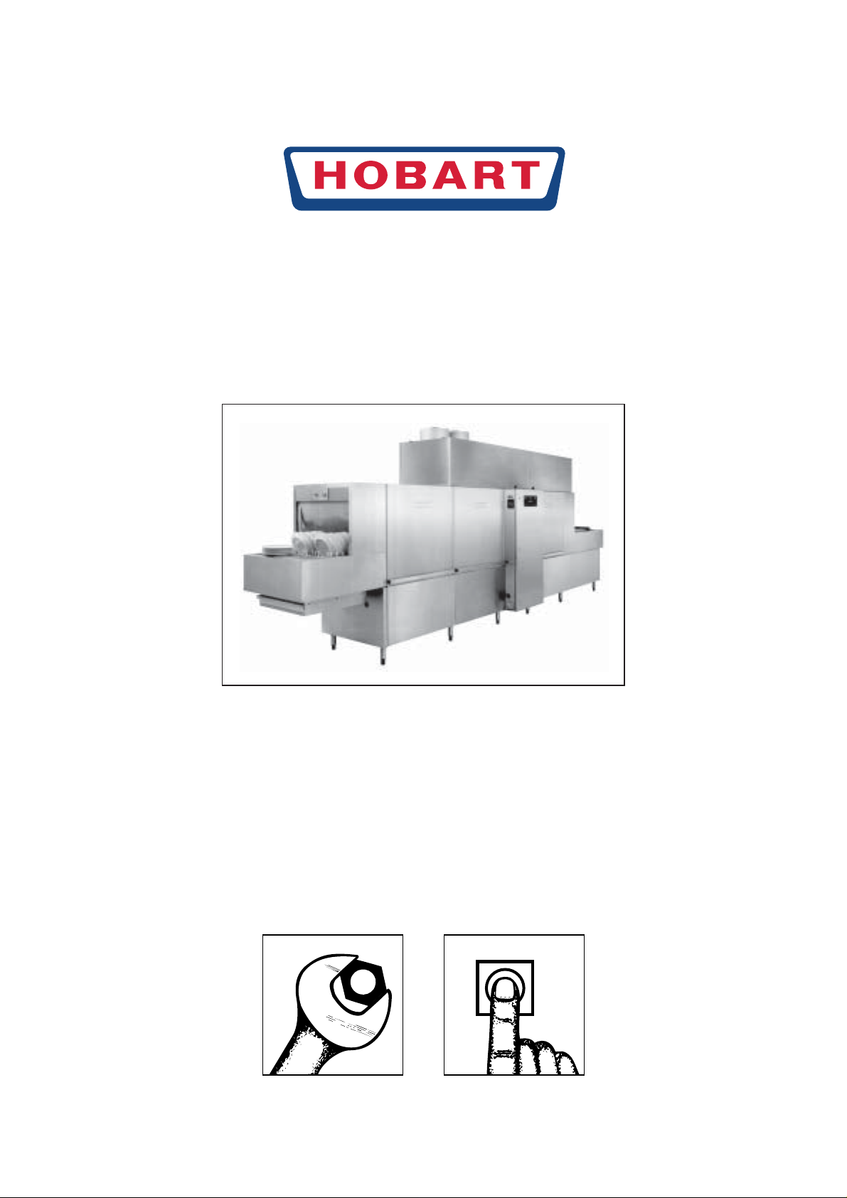
Warewasher
FTX Series
"Catering Systems"
(with Standard-Control el. heated)
INSTALLATION OPERATION
VERSION 02/02/05
Page 2

Installation and Operating Instructions
for Warewashers FTX Series
Content Page
1Assembly .............................................................................................. 3
2 Electrical connection ............................................................................. 6
3Water connections ................................................................................ 6
4 Exhaust connection............................................................................... 7
5 Detergent and rinse agent dispensing .................................................. 7
6 First run................................................................................................. 8
7Controls............................................................................................... 10
8 Preparation ......................................................................................... 14
9Operation ............................................................................................ 14
10 After dishwashing................................................................................ 16
11 Position of curtains.............................................................................. 17
12 Frost prevention .................................................................................. 17
13 Trouble shooting.................................................................................. 18
Machine noise level is 73 dB (A)
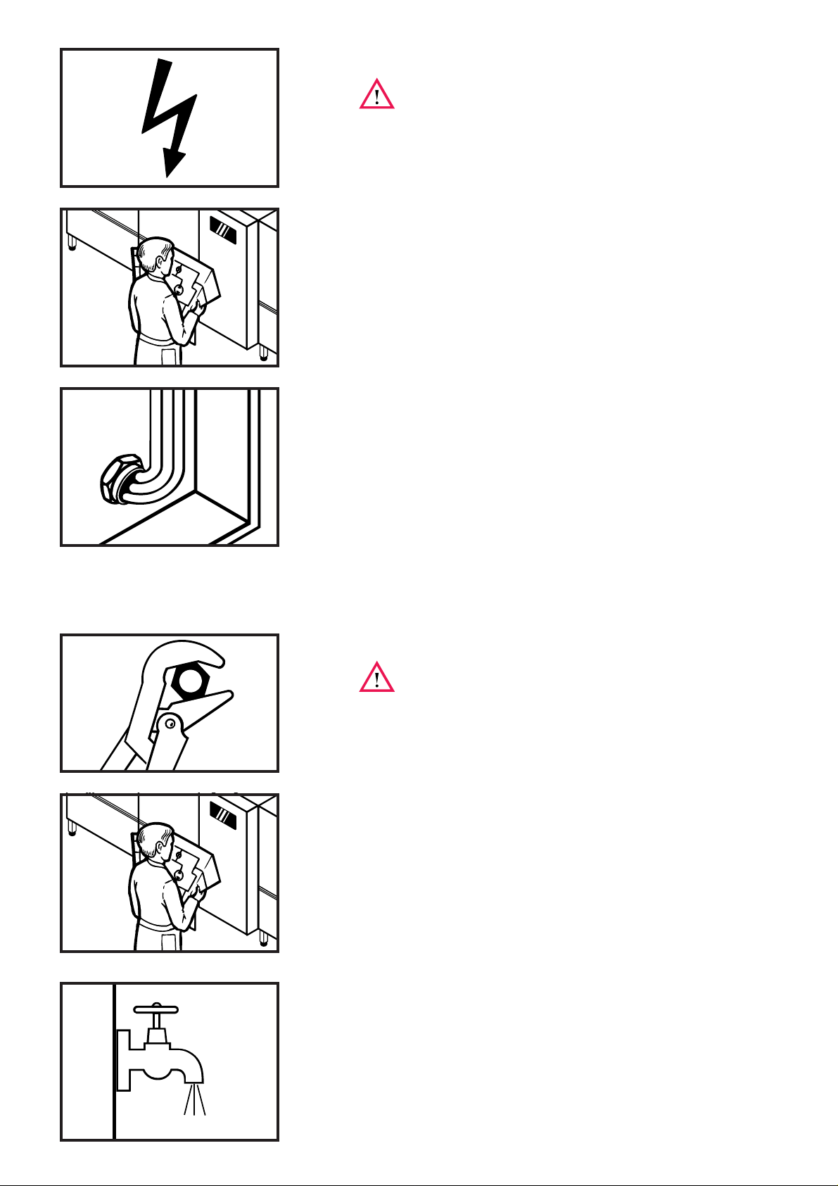
Important Notes
● Use in Accordance with Regulations
This machine is exclusively to be used to wash ware such as plates,
cups, glasses, cutlery, trays etc.
Do not use for electrically heated cooking and heat conservation
appliances.
● Safety
Never hose down the machine.
The "Attention" symbol is shown beside instructions that are essential
for the safe operation of the machine. Please read these passages
very thoroughly.
● Liability
Installations and repairs which are not carried out by authorized
technicians or the use of other than original spare parts, and any
technical alterations to the machine, may affect the warranty set
out in the standard conditions of sale.
2
Page 3
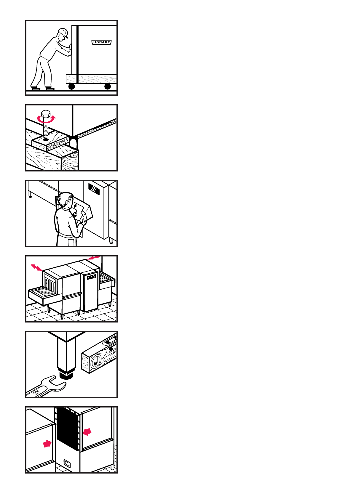
1 Assembly
Should be carried out by HOBART technician
1.1 Transport to installation location
– If possible in its packing and on skid.
– Push on rollers.
– Avoid damage to floor and doors.
1.2 Remove packing
– Cut steel bands.
– Remove carton.
– Remove wooden skid.
– Remove inside packing material and accessories.
1.3 Locating
– According to installation plan.
– Consider wall clearance according to installation plan.
– Consider length of tabling, conveyors, etc.
1.4 Adjusting of machine height
– to loading platform level of 860 mm above floor by turning
the feet.
– Level floor unevenness.
– Distribute machine weight equally onto all feet.
1.5 Assembly of modules
If machine is delivered in separate modules:
Put largest module in place and level.
3
Page 4
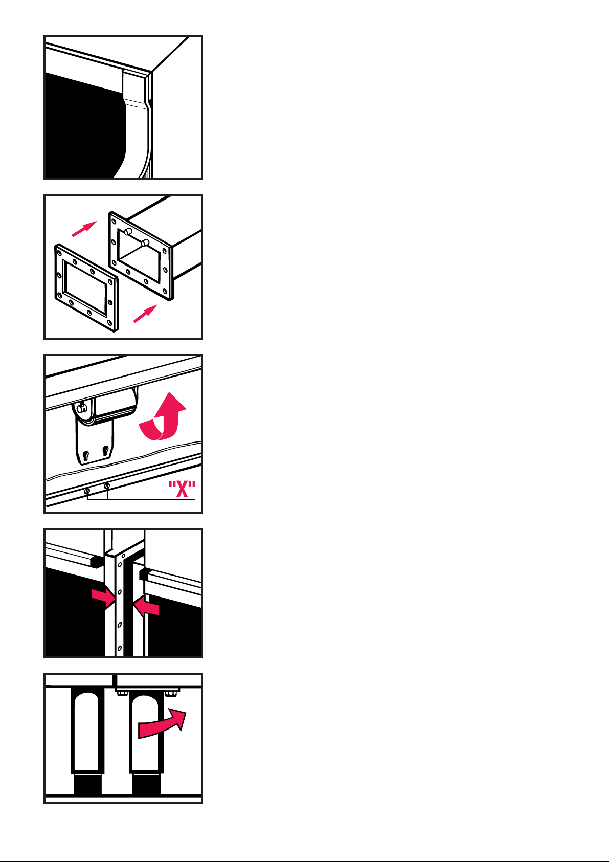
1.5.1 Sealing tape No. 168 834-1
must be stuck on one of the connecting surfaces.
– The sealing tape must overlap at the corners.
1.5.2 Flat gasket No. 229 161
must be stuck on overflow channel flange.
– If old gasket (from factory testing) is still fitted, this must be
removed previously and discarded.
1.5.3 Assembly is possible only with inspection doors removed.
– Loosen screws "X".
– Slide door up.
– Unhook springs from screws "X".
– Slide door up and remove.
1.5.4 Add next module
– Level height (see 1.4).
– Connect by using screws M6 x 12 hex. head, washers,
lockwashers and nuts (supplied).
– Cut protruding sealing tape with knife.
1.5.5 Transport feed
must be removed and returned to Hobart.
4
Page 5
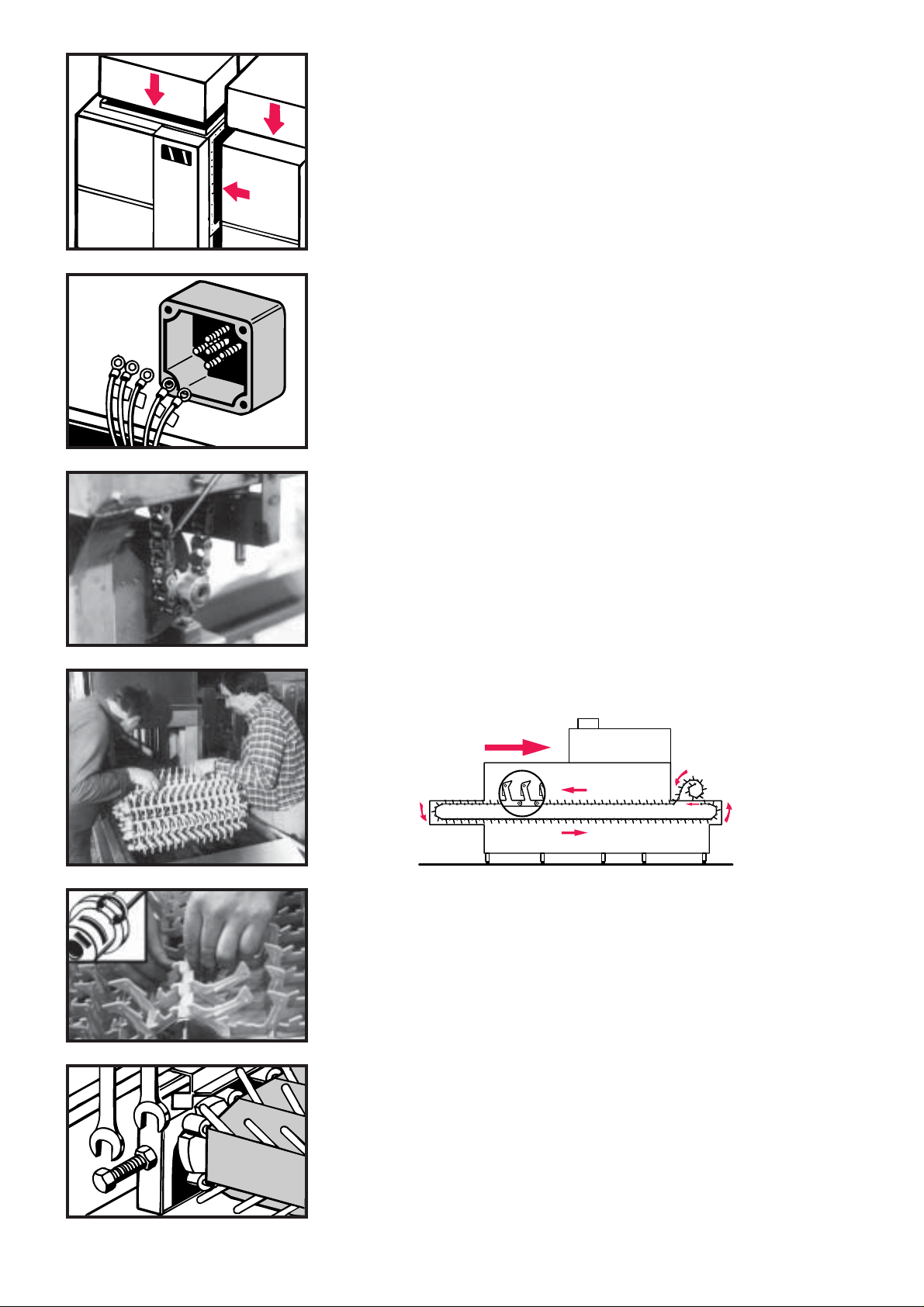
1.6 Condenser and drier
must be mounted according to separate instructions.
1.7 Electrical cables
must be unrolled and drawn through the cable channel.
– Connect wires to the terminals of the electrical components.
– Follow the wiring diagram and the labels on wires and
terminals.
1.8 Mounting the conveyor
– Remove chain between conveyor axle and transport motor
(end of machine).
– Put rolled conveyor on exit end of the machine and draw it
through the machine.
– Connect both conveyor ends by the conveyor rod and lock with
safety ring.
– Tension the conveyor at the loading section, equally on both
sides and lock tension screws.
– Replace chain between conveyor axle and transport motor.
5
Page 6
2 Electrical connection
must be carried out by an authorized technician
according to the national and local codes.
2.1 Check
– Open control box (with key) and take out wiring diagram from
the inside of the door.
– Check machine specifications to make sure they correspond to
those of the site supply and to wiring diagram.
– Check site fuse protection.
– Provide main circuit breaker close to the machine (if not built in).
2.2 Connection
– Draw cable through cable gland at the bottom of the control box
rear panel.
– Connect wires to main terminals or to main circuit breaker
(option).
– Tighten all terminal srews in the control box (may be loosened
during transport).
– Tighten all cable glands.
According to EN 60 335 the appliance must be connected to a
equipotential conductor. The connecting screw is located beside
the cable control box.
3Water connection
must be carried out by an authorized technician
according to the national and local codes.
The machine must be operated with water of drinking quality.
3.1 Check
– Make sure that site water supply and drain pipes correspond to
installation plan of machine.
– Identify which pipes are to be connected to corresponding
connections of machine.
– Check correct size of pipe inside diameters.
– Line strainer, pressure reducer, vacuum breaker and safety
valve are fitted to machine as standard.
For U.K.: rinse booster pump optional.
3.2 Fresh water supply for rinse 1/2" (For U .K.: 3/4" BSP)
– should be soft (0 to 4 °Clark, resp. 0,5 mmol/l).
–must be cold if condenser is fitted.
– Provide shut-off valve.
3.3 Fresh water supply for fill (if second connection fitted) 3/4"
– should be soft (0 to 4 °Clark) and warm (40 – 50°C).
– Provide shut-off valve.
6
Page 7

3.4 Drain connections
to be connected to site drain(s):
– Tank drains (50 mm Ø)
–DUAL rinse drain (hose 3/4")
–Drip water drains from drier and exit end of machine require
trapped drain connections.
For U.K.:
Use straight sleeve type TERRINE 213-15, 1 1/2" BSPT male.
Use tundish type drain raised above tank water level.
4 Exhaust connection
– Connection must be carried out in coordination with competent
ventilation engineer.
– Compare installation plan to site conditions.
Exhaust pipework
– Connect exhaust stack of 300 mm OD (not supplied) from
machine to site exhaust channel.
For U.K.: machine without ventilator:
connect exhaust stack of 147 x 477 mm.
– To prevent leakage, connect stack in such a way that
condensate water drops back into the machine.
– Air fan shown is to draw vapour through heat exchange
condenser, not to pressurise vapour through exhaust ductwork.
– In case of extremely low temperatures:
Provide insulation and anti-freeze shutter.
5 Dispensers
of detergent and rinse agent
– Normally, dispensers and controls are delivered and installed by
the detergent and rinse agent suppliers.
B
A
– Install dispensers, controls and containers such that they are
easy to handle and do not disturb machine operation.
– Rinse agent connections are provided for choice before (A) and
after rinse booster heater (B).
– Terminals are provided in the control box (see wiring diagr amme).
– Check for sufficient pre-dosage.
Use only commercial detergent and rinse agent.
Please pay attention to the manufacturers safety rules
and instructions.
7
Page 8

6 First run
A
Must be carried out to adjust and check machine functions.
See also chapter 7 (control elements).
Only to be done by an authorized
HOBART technician.
6.1 Preparation
– Switch off main switch.
– Check if detergent and rinse agent containers are filled.
– Open water supply.
– Open control box and switch on all circuit breakers and
motor protection switches.
Exception: if electrical rinse booster heater is installed:
make sure that its protection switch is switched off (see
wiring diagramme).
– Put strainers and curtains in place (see chapter 9).
– Close inspection doors.
– Switch on main switch.
– Switch on site exhaust extraction (if exists).
°C
B
III
0
III
B
– Set ON / OFF-switch to "fill" position.
When water sprays out of the rinse jets:
– Check if all rinse jets sprays correctly.
If not: remove rinse arms and clean jets.
– Push machine OFF button.
– Switch off main switch.
Electrically heated machine:
– Open control box and remove the film from the protection switch
of rinse booster heater (A). Switch on protection switch (B).
– Switch on main switch and push machine ON Button.
– After correct water level has reached, fill switches off
automatically and the tank heating(s) switch(es) on.
– When correct temperatures obtained (the green OK pilot light
illuminates), the machine is ready for operation. Push conveyor
ON button.
6.2 Fill rinse booster heater and tank(s)
8
Page 9

bar
l/h 100 200 300 400 500
bar
0,1
0,2
0,3
0,4
0,5
0,6
0,7
6.3 Check
– Direction of rotation of motors (see arrows on motors):
- pumps
- drier blower
- exhaust ventilator
– Check and eliminate possible leakages on:
- drain pipework
- water supply pipework, heating pipework
- machine housing, bottom of tanks, exhaust system.
6.4 Adjustment of flow pressure
at the pressure gauge of the rinse booster heater.
6.5 Adjustment of temperatures
Temperatures are adjusted at factory.
6.6 Detergent and rinse agent dispensing
should be adjusted by product specialist.
6.7 Adjustment of exhaust system
Must be carried out by HOBART technicians only during first run
with washware.
9
Page 10

7 Controls
5 6 7 9
°C °C
0
III
BACKWARD
III
?
21 3 4
14
8
13
NOT - AUS
11
10
O
I
12
15
10
Page 11

1 ON / OFF switch
Switches the machine on or off. Starts the fill cycle (exhaust and heating will start automatically).
2 Conveyor ON button
Switches the conveyor of the machine on. The wash cycle will be start automatically.
3 Conveyor OFF button
Switches the conveyor and wash off.
4 Conveyor speed selection switch
I = slow (e. g. for containers) II = middle (according DIN 10 510) III = fast (nominal speed)
5 OK pilot light (green)
Indicates, that the machine is ready for use.
6Temperature display – rinse 2
Indicates the current temperature of the pre rinse water (membrane filtration).
7Temperature display – final rinse
Indicates the current temperature of the final rinse water.
8Temperature display button
By pushing this button the display indicates individual temper atures of rinse or drier temperatures.
(see chapter 7.1)
9Warning light (red)
Indicates that one of the temperature probes is defective. The temperature display (6) indicates the Nº of the
defect probe, the temperature display (7) indicates the failure.
(e.g.: S = short circuit, L = open circuit)
10 Conveyor ON button at the loading section
Switches the conveyor of the machine on. The wash cycle starts automatically.
11 Conveyor OFF button at the loading section
Switches the conveyor and wash off.
12 Main switch
Must be in position I during operation and in position 0 during repair and maintenance.
13 Emergency Stop button
Switches the machine off. Must be unlocked for operation.
14 Backward key switch
By turning the switch clockwise, the conveyor belt will set a preadjusted distance backward.
(e. g. parts of washware are blocking the conveyor belt)
Danger of injury!
Must be carried out by an authorized technician !
15 Traffic light
Indicates the stage of the machines.
(e.g. green = the installation is ready; red / yellow = the installation has a fault)
The exact cause of fault, will be indicated at the screen of the central operation unit.
11
Page 12

BACKWARD
III
III
?
°C °C
°C °C
7.1 Temperature display
By pushing this button (8), individual temperatures (such as
pre-wash, wash, rinse or drier) can be displayed.
Press the temperature display button.
The rinse temperature displays (6) and (7) change into the
display mode. The temperature display (6) indicates the selected
measuring point, the temperature display (7) indicates the current
temperature.
Measuring point 1
Indicates the current wash temperature of the A-tank.
Measuring point 2
Indicates the current temperature of the B-tank.
°C °C
°C °C
°C °C
°C °C
Measuring point 3
Indicates the current temperature of the dual rinse.
Measuring point 4
Indicates the current temperature of the pre rinse (membrane rinse).
Measuring point 5
Indicates the current temperature of the final rinse.
Measuring point 6
Indicates the current temperature of the last drier.
12
°C °C
By pushing the temperature display button again, the display
changes back into the basic mode.
(Current rinse temperature display.)
Page 13

7.2 Faults
°C
°C °C
°C °C
If a failure arises during operation, it will be indicated by the
flashing of the red warning light.
– The flashing of warning light without other information at the
temperature displays (6) and (7), indicates a motor fault.
– The flashing of warning light and a further indication appears at
the temperature displays, it indicates a temperature probe
fault (short circuit or open circuit).
Example:
Pilot light failure illuminates and the left temperature display (6)
shows F 1, and the right display (7) shows an S or L.
This means:
The temperature probe F 1 failed by a short circuit (S) or a open
circuit (L).
III
°C
BACKWARD
III
III
?
BACKWARD
III
7.3 Conveyor reset
If parts of washware are blocking the conveyor belt, the machine
switches off (to avoid damages).
– The Warning light (red) of the tr affic light illuminates.
Danger of injury !
Must be carried out by an authorized technician !
– By turning the switch glockwise, the conveyor belt will set a
preadjusted distance backwards and the jammed piece can be
removed.
– The Warning light (red) switches off and by pressing the
Conveyor ON button the normal operation starts.
7.4 End-switch
Switches off transport if washware is not un-loaded from conve yor.
After washware is taken off from conveyor transport moves on
automatically.
The picture beside shows a machine without an additional
conveyor system. On machines with a roller conveyor on the exit,
the conveyor end switch wil be a roller.
13
Page 14

8 Preparation
Put curtains in place Check correct strainer position. Check wash arms.
(see chapter 12).
°C
BA
III
0
Close inspection doors (drains Check content of wash and rinse Start the conveyor by pushing the
close automatically). chemical containers. conveyor ON button. Wash and
Open water supply valve. Switch on main switch and set the rinse start directly.
Steam or hot water heated ON / OFF-switch to "fill" position.
machines: open heating valves. The machine starts fill and heating
automatically. Wait until the green
OK pilot light illuminates.
III
0
°C
III
9 Operation (Remove coarse food soil before washing.)
BA
III
Use loading platform to stack Load trays onto conveyor Do not mix trays and plates
plates. crosswise. (shadow zones).
Slide plates on conveyor.
14
Page 15

Put soup cups with inclination to the Do not place soup cups vertically Put glasses and cups with the
machine on 2 pegs of conveyor. on conveyor. opening facing downwards into
the rack. Glasses should not touch
each other (glass fracture). Use
the correct rack.
Put cutlery vertically and unsorted Wash utensils in utensil rack. Put gastronorm pan and other bowls
with handle downwards into cutlery Put the rack on conveyor. Check with openigs facing downwards on
racks. that no grips or handles protrude conveyor, with inclination to the
Set the cutlery racks on a utensil through the rack or conveyor. machine.
rack and put them on conveyor.
Pass through insulated trays with Do not set the insulated trays with Let the washware be conveyored
the opening downward and cross- opening upward on conveyor. almost to the end of the conveyor
wise. Water will pool in the sections. to give enough time to dry.
Washware may not exceed maximum loading height and width.
15
Page 16

10 After dishwashing
B
°C
III
0
Push Conveyor OFF button. Close shut-off valves. Remove and clean wash arms.
Turn the ON / OFF selector to "0" Remove and clean strainer basket
position. Switch off main switch and flat strainers.
and open inspection doors.
III
Take out curtains. Drain tanks by lifting lever at left Hose down interior of machine and
tank wall. conveyor.
Leave doors open for ventilation.
1
2
Put strainer baskets and flat Put curtains in place. Remove and check rinse arms
strainers back into place. once a week.
16
To clean the machine do not use any chloric, acidic or abrasive products
and no metallic brushs.
Never hose down the exterior of the machine.
Leave the doors open for ventilation.
Page 17

11 Position of curtains
2 2 2 2 2 2 12 2
SABRD2TT D2 D2A
?
FTX 4-SB-6, D2TT, D2, D2A
1
2
13 Frost prevention
Set main switch to "0".
The contactors of the heating elements for the booster should
be disconnected!
All tanks, water pipework and armatures must be totally drained:
– Turn out plug at the bottom of the rinse booster heater.
– Loosen unions next to fill valve.
– Drain site water pipework.
– Drain traps of drain system.
– Steam/hot water heated machines:
drain all heating coils and pipes.
– The condenser – if fitted – must be blown out with
compressed air.
– Reset for operation according to chapter 6.
17
Page 18

14 Troubleshooting
Failure Cause Correction
Tank fill too slow. Line strainer of fill clogged. Clean line strainer.
Solenoid valve defective. Replace solenoid valve (coil).
Tank not filled to correct Overflow / drain leaking or missing. Check overflow / drain gasket.
level.
Vapour escapes from Too low exhaust extraction. Adjustment by HOBART service.
loading or exit section.
Temperatures too low. Too much exhaust extraction. Adjustment by HOBART service.
Dishes soiled after washing. Strainers wrongly positioned. Check strainers.
Fill cycle too short. Adjust fill cycle, follow chapter 6
Too much wash water splashes Check wash arms, curtains and deflector panels.
into loading section. Put dishes correctly on conveyor.
Too much foaming. Use non-foaming detergent only.
Drier blows into machine. Lower slide of drier jet.
Put dishes correctly on conveyor.
Heaters defective. Check heaters and thermostats.
Curtains not or wrongly placed. Check curtains (see chapter 11).
Wash jets clogged. Clean the wash arms.
Too low detergent concentration. Increase detergent dispensing.
Temperatures too low. Check heating system.
Washware wrongly positioned See chapter 9.
Food soil dried-on. Soak dishware before washing.
Streaks and spots on Strainers wrongly positioned. Check strainers.
dishes.
Dishes do not dry. Incorrect temperature or humidity of Check heater and blower of drying unit.
Drops on dishes. Inadequate rinse agent concentration. Increase concentration or change product.
Dishes tilt over. Water pressure from below too high. Replace reducer between lower wash arm and
Wash water splashes into rinse section. Check curtains (see chapter 11).
Rinse jets clogged. Clean rinse jets.
Inadequate rinse agent dispensing. Adjust dispenser.
Too high mineral content of water. Use of demineralized rinse water recommended.
of drying air.
Washware still greasy. Increase detergent dispensing.
wash pipe.
Upper wash arms clogged. Clean wash arms.
Items too light. Put dishes into racks and put cover on racks.
As continued product improvement is a policy of HOBART, specifications are subject to change without notice.
Printed in Germany AG-21331-A-01-05-PC
 Loading...