

Page 1
SERVICE TRAINING CENTER
This document is destined for internal use only.
The discribed settings and servicing must be carried out by
service technicians qualified by HOBART.
Reproduction of this document is prohibited without the written
permission of Hobart GmbH.
© HOBART GmbH, Service Training Center
Issue: 2005-04
SERVICE MANUAL
CONVEYOR RACK TYPE DISHWASHER
CNA
PRESSURE BOOSTER SYSTEM / EPROM rev. 3.00
Page 2

Important Note
For filling and first run the technician need this manuals,
and he must follow the instructions to prevent damage of the
booster heating elements
Page 3

Page 2 – CNA Series (rev. 3.00) © HOBART GmbH, Service Training Center
SERVICE TRAINING CENTER
CONTENTS
CNA MODULES ................................................................................................................................... 3
TECHNICAL DATA ............................................................................................................................... 4
MACHINE DOCUMENTS ..................................................................................................................... 4
CONTROLS .......................................................................................................................................... 5
INITIAL OPERATION ........................................................................................................................... 6
WATER CIRCULATION AND HEAT BALANCE .................................................................................. 7
FUNCTIONAL DESCRIPTION ............................................................................................................. 8
OPERATION .................................................................................................................................... 8
TANK FILL ....................................................................................................................................... 8
BOOSTER ....................................................................................................................................... 8
WASH OPERATION ........................................................................................................................ 8
AUTOTIMER .................................................................................................................................... 9
DRAINING ..................................................................................................................................... 10
SAFETY CIRCUIT ......................................................................................................................... 11
DOOR SWITCH ............................................................................................................................. 11
FLOAT SWITCHES ........................................................................................................................ 11
TEMPERATURE SENSORS .......................................................................................................... 11
WASH SYSTEM ................................................................................................................................. 12
WASH PUMPS .............................................................................................................................. 12
WASH ARMS ................................................................................................................................. 13
LATERAL WASH (OPTION)........................................................................................................... 14
E-PREWASH ................................................................................................................................. 14
RINSE SYSTEM ................................................................................................................................. 15
FINAL RINSE ................................................................................................................................. 15
PRE-RINSE SYSTEM ......................................................................................................................... 16
DUAL RINSE.................................................................................................................................. 16
TRIPLE RINSE .............................................................................................................................. 17
RINSE PUMPS ................................................................................................................................... 18
TANK AND BOOSTER HEATING ...................................................................................................... 18
ELECTRICAL HEATING ................................................................................................................ 18
HEAT RECOVERY .............................................................................................................................. 19
DISPENSERS ..................................................................................................................................... 19
CONTROL PANEL ............................................................................................................................. 19
CONVEYOR SYSTEM ........................................................................................................................ 20
MACHINE CAPACITY .................................................................................................................... 20
TABLE END SWITCH .................................................................................................................... 20
CONVEYOR SAFETY MECHANISM ............................................................................................. 20
TRANSPORT SYSTEM ................................................................................................................. 20
REPLACEMENT OF GEAR MOTOR ............................................................................................. 20
POSITION OF CURTAINS .................................................................................................................. 21
FAULT DISPLAY................................................................................................................................. 22
STARTING FROM EPROM REVISION 3.00.................................................................................. 22
UP TO EPROM REVISION 2.00 (FOR INFO) .............................................................................. 23
Page 4
SERVICE TRAINING CENTER
© HOBART GmbH, Service Training Center CNA Series (rev. 3.00) – Page 3
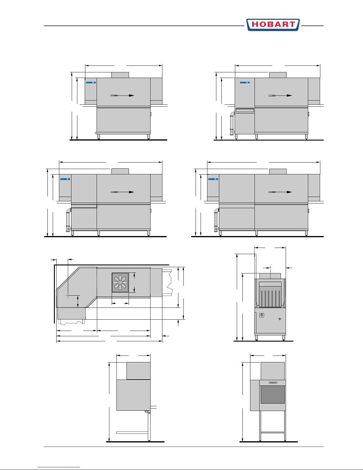
CNA MODULES
790
391
2.150
1.950
1.576
1.718
2.600
2.850
1.576
1.718
1.576
1.718
1.576
1.718
1.350
430
2.375 300
1.025
2.675
1.025300
1.325
2.208
1.718
500
303
300
850 900
2.013
2.013
CNA CNA-E
CNA-L
CNA-C
CDS CDC
CNA-S
Page 5

Page 4 – CNA Series (rev. 3.00) © HOBART GmbH, Service Training Center
SERVICE TRAINING CENTER
TECHNICAL DATA
MODEL CNA CNA-E CNA-L CNA-S CNA-C
Capacity (racks - plates / hour)
standard 120 - 2160 150 - 2700 180 - 3240 220 - 3960 180 - 3240
accordant DIN0510 80 100 120 150 120
Prewash
Pump load (kW) – 0.3 1.1 1.5 1.1
Delivery rate (l/min) – 250 740 1020 740
Tank volume (l) – 30 54 100 54
Wash
Pump load (kW) 1.5 1.5 1.5 1.5 1.5
Delivery rate (l/min) 1020 1020 1020 1020 1020
Tank volume (l) 100 100 100 100 100
Rinse
Water consumption (l / hour) 260 260 260 260 260
Dryer
Heating (kW) 4.5 / 9 4.5 / 9 4.5 / 9 4.5 / 9 4.5 / 9
Air circulation (m-/h) 1800 1800 1800 1800 1800
Fan motor (kW) 0.42 0.42 0.42 0.42 0.42
Equipment
2 speeds yes yes yes yes yes
Auto-timer Option Option Option Option Option
Isolating switch Option Option Option Option Option
Dual rinse yes yes yes yes yes
Tr iple rinse Option Option Option Option Option
Heat recovery C30 Option Option Option Option Option
Heat pump CHP18 Option Option Option Option Option
MACHINE DOCUMENTS
Wiring diagrams and general machine data are stored
in a pocket at the rear of the hinged electric box.
Page 6

SERVICE TRAINING CENTER
© HOBART GmbH, Service Training Center CNA Series (rev. 3.00) – Page 5
1. Machine ON / OFF Pushing this button switches the dishwasher on or off.
NOTE: After switch off, the machine is not voltage free! At the temperature
indicator Rinse appears a point.
2. Start / Stop button – Conveyor / Wash
Pushing this button starts the conveyor with the selected speed.
The button illuminates to indicate the mode of the machine:
RED =machine fills and starts heating
GREEN =machine is ready for operation
BLUE =washing on
When the button flashes:
RED = when switching on the machine: machine is filled but heating-up
fault: the temperature indicators display a code
GREEN =machine refills and heats up
BLUE = program started, but machine is not ready for operation
3. Conveyor speed button By pushing this button, it is possible to select between two pre-set conveyor
speeds. The selected speed will be indicated.
By pushing this button for approx. 4 seconds, temperatures will be indicated.
"Ch0" = rinse / "Ch1" = wash
"Ch2" = prewash (option – activated by S03 in configuration mode)
The temperatures will be displayed one after the other by repeated pushing the
Conveyor speed button.
The indicators go out 10 seconds after releasing the button.
4. Conveyor speed indicator Indicates the selected speed.
= slow = fast
When the conveyor speed indicator flashes, the table end switch is activated [1S6].
5. Temperature indicators Indicates the current temperature:
Temperature indicator Rinse (°C)
Temperature indicator Wash (°C)
With a machine malfunction, the temperature indicators display a code.
6. Drain button By pushing this button for approx. 2 seconds, only the prewash tank will be
drained.
The drain button illuminates and the Start / Stop button illuminates red.
After a pre-set time (C04) drain cycle stops and the machine will be refilled
automatically.
To drain the machine completely, push drain button for approx. 4 seconds.
The drain valves will be controlled via adjustable time delay [C05].
The Drain button illuminates and the Start / Stop button switches off.
CONTROLS
5 Emergency Stop
(option)
231 46
Page 7
Page 6 – CNA Series (rev. 3.00) © HOBART GmbH, Service Training Center
SERVICE TRAINING CENTER
INITIAL OPERATION
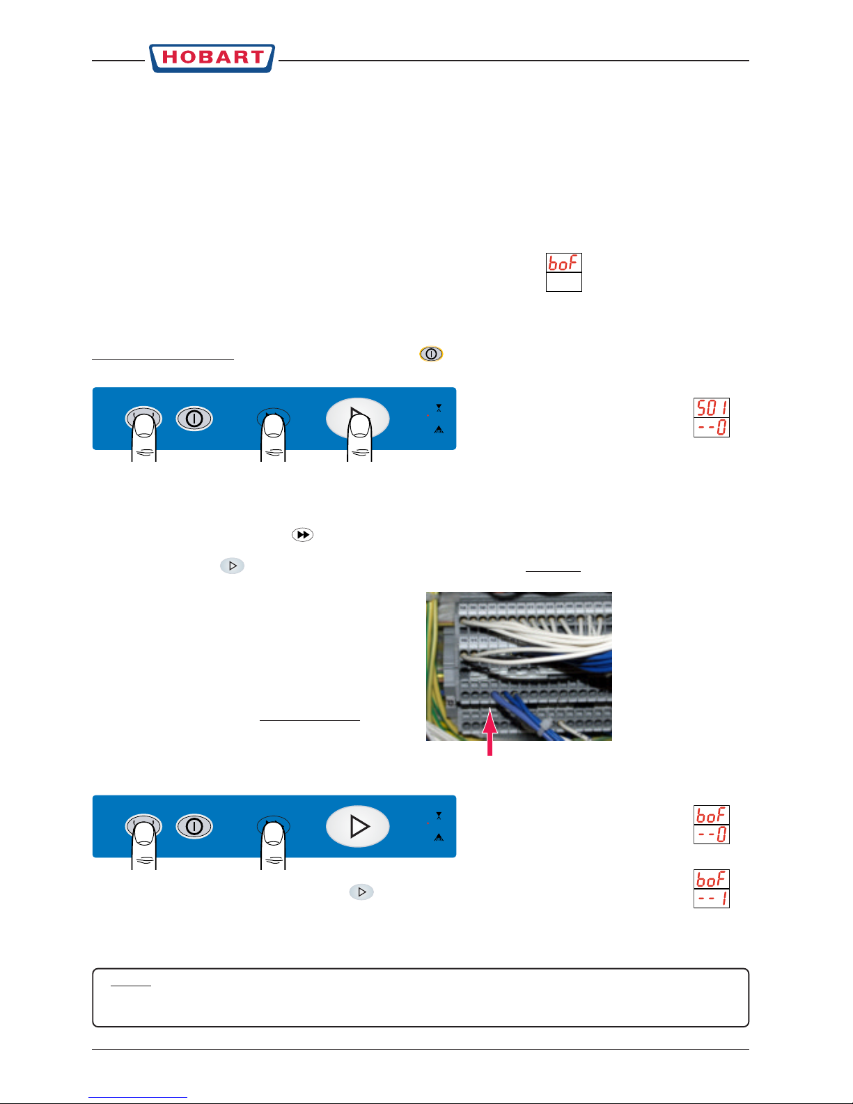
FILLING THE RINSE BOOSTER FOR THE FIRST TIME
This is necessary after setting the machine type, when the dishwasher has been initially installed or when the
booster has been drained (to prevent frost damage or to replace heating elements for instance).
– Remove lower front panel and switch on all circuit breakers and motor protection switches in the control box.
– Open shut-off valves at site and switch on main switch.
When switching on the machine, the temperature indicator displays flashing:
This indicates that the booster is empty and requires filling.
For the initial fill of pressure booster, the rinse pump has to be energised. This can be carried out via the test
mode after the break tank is filled (via mechanically operated float valve):
Switch off the machine by pushing the ON/OFF button
and open the doors.
Push and hold the drain, conveyor speed and Start / Stop button together.
The temperature indicators display:
S01S01
S01S01
S01
corresponds to the first tested
input (doors) of the control board.
Close the doors. The wash temperature display changes to
--1--1
--1--1
--1
.
Generally the switch settings are displayd with
--1--1
--1--1
--1
when activated (close) and
--0--0
--0--0
--0
when inactive (open).
Push the Conveyor speed button repeatedly until the temperature indicator rinse displays "
A17A17
A17A17
A17
"
(output rinse pump).
Push the start button
(
--1--1
--1--1
--1
appears in the wash temperature display) and hold until water sprays
out of rinse nozzles.
Switch off main switch.
Remove electr. control cover and put the provided
jumper on X2 (16/17).
Put the control cover and front panel in place.
Switch on main switch but not the machine.
Open doors, push the drain and conveyor speed button together.
The temperature indicators display:
To clear the message, push the start button . The temperature indicators display:
The wash temperature display will change immediately to
--0--0
--0--0
--0
.
Close the doors. The indicators go out and the machine is now ready for operation.
NOTE:
After setting the machine type or reset of the parameter C28 to "0",
BOFBOF
BOFBOF
BOF
will also be indicated and
the initial booster fill has to be repeated.
Page 8
SERVICE TRAINING CENTER
© HOBART GmbH, Service Training Center CNA Series (rev. 3.00) – Page 7
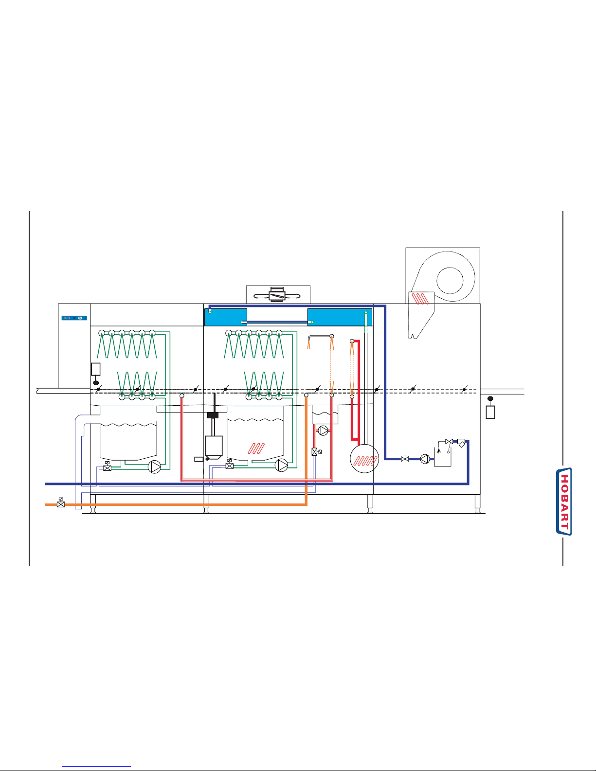
WATER CIRCULATION AND HEAT BALANCE
ca. 60°C
3 g/l
1.5 g/l
ca. 10°C
> 45°C
blocking
1S5
auto-timer
1S1
ca. 55-60°C
ca. 45°C
ca. 70°C
900l/h
M
1B6
1Y11
3Y1
2B2
30°C
600 m
3
/h
2Y1
1Y2
1B2
1S6
table end switch
ca.85°C
260l/h
rinse agent dosage
ca. 0.5 g/l
CNA-S-CDS
with triple-rinse
Page 9

Page 8 – CNA Series (rev. 3.00) © HOBART GmbH, Service Training Center
SERVICE TRAINING CENTER
FUNCTIONAL DESCRIPTION
OPERATION
When the machine is switched off, a luminous red point (at the rinse temperature display)
indicates that the machine is connected to the main power supply.
Switching on the machine:
Note:
When switching on the machine, a test program of the control (inputs and outputs) will run and the
control panel is locked during this time. Therefore you should wait approx. 5 sec., before commands are
given via control panel.
When the doors are closed and the machine is switched on by pushing the ON/OFF button
, fill will be started.
TANK FILL
Via separate fill valve (hot water connention) [S18 = 1]
The machine will be filled by the cascade principle via warm water valve 1Y2.
When all float switches [1B2 & 2B2] of the machine are activated, the heatings in the respective tanks will be
switched on.
Then the machine will be overfilled via adjustable time [C02] (see service mode).
Refill during operation is controlled via timer [C03].
The conveyor start button illuminates red
during the fill and heating phase and will change to green light
when all operation temperatures (adjustable) are reached.
Via booster: machines with 1 cold water connection [S18 = 0]:
When the machine is switched on, first the booster will be heated [1K1]. If 70°C [F01] are reached, the rinse
pump 1M3 will start and the tanks will be filled via the rinse pipes.
Machine fill via booster can be temperature-controlled by parameter [S14 = 1].
In this case the booster will be heated up to 70°C before the rinse pump 1M3 will be started to fill the machine.
If the temperature drops below 48°C, fill (rinse pump) will be stopped until the booster has reached 70°C again.
Fill time control
The fill time of the machine will be controlled via adjustable time [C09] (base value = 30 min).
When the respective float switch has not close after this time period, the error message FIL 002 will be displayed.
The fault will be cleared as soon as the float switch closes again.
The filling of the machine remains activated when the failure occurs.
NOTE: The exhaust ventilator will also be controlled during the whole fill time.
BOOSTER
When the machine is switched on, the pressure pump will be started for approx. 5 sec. [C17] to guarantee refilling
of the pressure booster in case of water loss (e. g. evaporation or leakage during a longer standstill period).
During the machine tanks are filled, the booster will be heated up to 70°C [F01].
When the tanks are filled ( after time delay [C02] ), the booster will be heated up to 85°C ( set value [F02] ).
WASH OPERATION
When the machine is ready for operation, the conveyor can be started by pressing the conveyor start button
.
The conveyor speed (slow / fast) will be selected by pressing the conveyor speed button and indicated
by the LED.
Note:
The conveyor can only be started when the machine is filled (re-fill completed) and the set value of 85°C
is reached in the booster.
Page 10

SERVICE TRAINING CENTER
© HOBART GmbH, Service Training Center CNA Series (rev. 3.00) – Page 9
FUNCTIONAL DESCRIPTION
AUTOTIMER
As a rack enters the machine, the auto timer actuator lever (magnet) triggers
a reed switch [1S1] and the wash functions of the machine will be started.
Each signal of the magnet activates a time delay which will stop the wash
function when the last rack has passed the machine (autotimer) [C08] / [C44].
The conveyor is still working and wash will start again as soon as a rack enters
the machine (lever pulse).
For every speed a separate wash time via autotimer is adjusted. At speed 1 (slow)
the autotimer is controlled via time [C08] and at speed 2 (fast) via [C44].
If during wash operation the table end switch [1S6] is activated by a rack, the conveyor will be stopped
immediately as well as rinse and pre-rinse if activated.
If the rack isn’t removed, the wash pumps will stop after 45 sec. [C06].
The activated table end switch [1S6] will be indicated by the flashing conveyor speed indicator.
If the end switch is free, the conveyor will start again with the chosen speed. Rinse and pre-rinse will also be
started if activated by a rack.
The autotimer [C08] or [C44] will be reactivated and wash will be started again.
Autotimer rinse
auto timer switch 1S1
(at machine entry)
01-242189-1 (L/R)
01-242189-2 (R/L)
After wash is switched on via autotimer [1S1], pre-rinse (option) and
final rinse will be activated time delayed (depending on chosen conveyor speed) for a preset time.
The rinse period is also adjustable according to conveyor speed.
At speed 1 (slow) rinse will be started time delayed via [C46] after the rack switch [1S1] was activated.
The rinse time is given by [C47] and by the contact time (rack length) of switch [1S1].
So the rinse time is equal [C47] + contact time of [S1].
Every new rack will be registered, the respective time will be measured and executed. The rack before will keep
its turn on and turn-off times.
If the conveyor was stopped (e.g. by the table end switch or by the operator), the times will be stored and the
autotimer functions will proceed after restart.
transport motor
2 speeds
(factor 2/3)
rack entry detection
1S1
parameter
at speed 2
parameter
at speed 1
pre-wash main wash (AR) dual and final rinse dryer
switch-on delay rinse [C46] rinse time [C47]
+ rack length
switch-on delay rinse = [C46] x [C50] (%) rinse time [C47] x [C50] (%)
+ rack length
auto-timer wash [C08]
auto-timer wash [C44]
Page 11

Page 10 – CNA Series (rev. 3.00) © HOBART GmbH, Service Training Center
SERVICE TRAINING CENTER
FUNCTIONAL DESCRIPTION
The functions of conveyor speed 2 (fast) are the same as described for speed 1.
As the rack enters the pre-rinse (option) and final rinse zone faster than with speed 1, other times are required.
This time will be proportionally calculated of parameter [C46] which corresponds to the slow speed.
The conversion factor is indicated in % via [C50] and is normally set to 67%. This value corresponds to the
transmission between slow and fast speed of the conveyor motor.
The effective rinse time of a rack will be calculated the same way via [C47] and [C50].
NOTE:
If during wash operation the machine will be refilled or a temperature drops below the preset value, the
blue illuminated conveyor start button will flash until the normal operation conditions are reached again.
During stand-by the conveyor start button is flashing green in this case.
Automatic conveyor switch-off
After wash is switched off via autotimer, the conveyor will be stopped automatically after the adjustable
time [C07 = 300 sec.].
To start again, the conveyor start button must be pressed or a rack must enter the machine.
The automatic re-start via rack switch [1S1] is only possible after the
conveyor has been started one-time by pushing the start button.
Mechanical rinse switch (option)
The autotimer rinse function (controlled by the software) can be realized
alternatively via an additional mechanical switch.
Pre-rinse and final rinse will be started as long as the switch is activated.
With this option the parameters [C46] and [C47] must be set to "0".
Parameter [S01] (configuration) must remain activated resp. set to "1".
DRAINING
Partial draining
Pressing the drain button for approx. 2 sec. will initiate a partial draining of the machine if prewash tank is
installed [S03 = 1].
The drain button illuminates
and the conveyor start/stop button illuminates red
.
The drain valve of the prewash tank will be activated for an adjustable time [C04]. After this time period the
valve will be closed and the prewash tank will be refilled.
Complete draining
Pressing the drain button for approx. 4 sec. will initiate a complete drain of all tanks.
The drain button illuminates
and the red conveyor start/stop button switches off
.
All drain valves will be activated for an adjustable time [C05]. After this time period the valves will be closed and
the machine will be switched off (ON/OFF button is no longer illuminated).
If the machine will be switched off before draining (partial or complete) has finished, only the drain button remains
illuminated.
To stop a drain cycle, machine must be switched OFF and ON again (ON/OFF button).
Draining (partial or complete) can also be done with doors open.
Drain control
When drain cycle is completed resp. the drain valves close (after time period C4 & C5), the float switches
of the respective tanks must be free again.
If not, an error message will be displayed (see also page 22):
AL1 = drain fault – prewash tank / AL0 = drain fault – wash tank.
mechanical
rinse switch in the
AR zone
Page 12

SERVICE TRAINING CENTER
© HOBART GmbH, Service Training Center CNA Series (rev. 3.00) – Page 11
FUNCTIONAL DESCRIPTION
SAFETY CIRCUIT
The security circuit controls the doors and the conveyor system (motor protection and
jam switch) [1S5].
If the circuit is interrupted, wash functions will be switched off and only the heaters will
be activated.
NOTE:
The safety circuit does not control the release of motor protection switches (wash pump motors etc.) and
therefore it will not display any fault.
DOOR SWITCH
The door reed switch is located behind the front panel at the lower
tank support, the magnet is fitted at the door stop.
The door contacts [..S2] are wired with the safety circuit and
interrupt the washing functions of the machine.
The door contacts must be connected to the wiring harness with
plugs which can be replaced by AMP-plugs if defective.
FLOAT SWITCHES
All tanks are equipped with a float switch which will activate or switch off
the heater (depending on temperature).
The float switch is a change-over contact which will disable the fill contact
and enable the heating at upper level [..B2] (1-2 opens, 1-3 close).
TEMPERATURE SENSORS
The temperature sensors (NTC) can be checked by resistance measuring.
Check also for earth fault as this can cause galvanic currents which could result in pitting corrosion.
For this test (500 V DC, R > 1 M Ohm) both wires must be short-circuited to prevent damage of the sensors.
The temperature sensors are attached to the exterior wall of the respective wash tanks and booster.
Te mperature adjustment is not possible.
temperature resistance temperature resistance
°C kOhm °C kOhm
0 35.979 60 3.243
1 34.325 65 2.745
5 28.519 70 2.333
10 22.765 75 1.990
20 14.774 80 1.704
30 9.787 85 1.464
40 6.653 90 1.262
50 4.608 100 0.950
55 3.856
Page 13

Page 12 – CNA Series (rev. 3.00) © HOBART GmbH, Service Training Center
SERVICE TRAINING CENTER
WASH SYSTEM
WASH PUMPS
Modul pump load delivery rate tank volume
prewash E 0.2 kW 250 l/min 30 l
prewash L 1.1 kW 740 l/min 54 l
prewash S 1.5 kW 1200 l/min 100 l
prewash C 1.1 kW 740 l/min 54 l
wash AR 1.5 kW 1200 l/min 100 l
Replacement of the mechanical shaft seal
1. Remove clamps (1) & (2). Take down the pump, turn over and set it
down onto the motor. Be carefully that no water run into the motor.
2. Loosen the self-locking nut (3) and remove washer (4) & spacer (5).
3. Remove the impeller (6).
4. Dismantle the shaft seal (7).
5. Clean shaft and support before fitting the new shaft seal.
6. Installing the the new shaft seal 324 815-4 :
a) Wet the rubber collar of the ceramic part with rinse aid.
b) Press ceramic part right-angled into place. The ceramics
surface must not be damaged.
c) Clean the ceramics surface and wet it with paraffin oil.
d) Wet the inner rubber ring oft the shaft seal with rinse aid
and put some paraffin oil to the sealing face.
e) Press shaft seal against the ceramic ring.
7. Reinstall carefully the impeller.
8. Mount spacer (5), washer (4) and nut (3) and tighten.
9. Use new o-ring (8) 276903-27 & (9) 276903-31 for
reassembling the pump.
Wash pump construction
To optimise the pump capacity, a throttling ring (10)
is fitted between lower part of pump housing (11)
and impeller (6). Pay attention to mounting direction!
When the pump housing will be replaced, a new
o-ring (12) 276903-28 must be fitted.
NOTE : If the shaft seal is leaky, the o-ring (13) prevent water
splashing into the motor. The water run into the upper pump
housing (14). Therefore let it drain before turning the motor
on top when dismounting
Cr-Ni cover 695797-39 is available for machine installation.
Impeller Part no. Pump
Ø168 mm 774 146-1 1.5 kW/ 50Hz
Ø152 mm 774 147-1 1.5 kW/ 60Hz
Ø120 mm 774 146-2 1.1 kW/ 50-60Hz
11
4
5
13
3
10
1
8
6
2 9
12
7
14
Page 14

SERVICE TRAINING CENTER
© HOBART GmbH, Service Training Center CNA Series (rev. 3.00) – Page 13
WASH SYSTEM
WASH ARMS
The wash arms consist of a different number
of pipes with 7 nozzles per pipe:
wash arm upper lower
L prewash 3 pipes 1 pipe
S, A wash 6 pipes 4 pipes
C prewash 4 pipes 3 pipes
The illustration shows the wash system of a
main wash tank.
The rounded plastic manifolds (3) are
mounted to the rear surface of tank and fixed
with plastic nut (4) and gasket (5) from inside.
This nut serves as wash arm support.
The wash pipe gasket (6) will be pressed into
nut (4) and fixed with the diaphragm (7).
To mount the wash arm (1) set it in side
guides (8), move to end position and drop-in
over stop unit (9).
To remove the upper wash arm press latch
(see arrow), lift wash arm over stop unit and
pull out.
The front of the wash pipes will be sealed by
pressed-in rubber plugs (13).
Special tool is needed for the replacement of wash
arm guides resp. manifold (available as ring wrench
695797-36 or socket wrench 695797-81).
To avoid tilt over of dishes and to reduce splash over of wash water, the
upper wash arms are placed in such a way, that the first two water jets
do not hit a lower one.
Diaphragm
Every nut (4) is provided with a diaphragm (7 + 12) to distribute the pump pressure on upper and lower wash
arms in a way, that a good washing result will be achieved with different kinds of washware and dishes do not
tilt over.
diaphragm "C" corner "L" prewash "S" prewash +
Ø / part no. prewash AR wash
14 mm / 885 538-4 lower arm lower arm
24 mm / 885 538-1 upper arm upper arm upper arm
12 mm / 885 538-6 lower arm
9
10
13
1
2
3
8
12
11
7
6 4
5
11
8
operating direction
Page 15

Page 14 – CNA Series (rev. 3.00) © HOBART GmbH, Service Training Center
SERVICE TRAINING CENTER
WASH SYSTEM
LATERAL WASH (OPTION)
The part (1) shows the wash nozzle at the back side (3 x) which is
mounted to the manifold by means of a nut.
An additional wash pipe (2) with three nozzles is fitted on front side.
The parts (1) and (2) are different on machines with left-to-right or
right-to-left operating direction. The water jet is directed against the
operation direction.
2
1
1
2
2
3
3
E-PREWASH
The "E" prewash system consists of a 30 l
tank and two wash arms (2), supplied by a
0.2 kW pump (1) with a delivery rate of
250 l/min.
The wash arms (2) are equipped with a
diaphragm (3) to ensure a pressure of 0.2
bar (upper) resp. 0.1 bar (lower).
Page 16

SERVICE TRAINING CENTER
© HOBART GmbH, Service Training Center CNA Series (rev. 3.00) – Page 15
RINSE SYSTEM
The rinse zone is connected to the last wash tank (AR module) as standard.
The rinse zone consist of two systems, prewash (option) and final rinse.
FINAL RINSE
The final rinse water is needed to remove residual detergent and to reduce the surface tension in combination
with rinse aid. The temperature of 85°C enables dishes to dry and ensure the hygiene regulation.
The water streams through the line strainer into the break tank (1) (airgap). The water level in the break tank is
controlled by the mechanically operated float valve (2).
The rinse pump (3) delivers the water through the condensers (C1 and C2) and through the booster (8) into the
final rinse arms. In the condensers the water will be heated up to approx. 40 - 45°C.
The booster (8) will heat the water to 85°C. The heating elements (11) are controlled by a temperature sensor (10).
The safety relief valve (9) shall prevent that the pressure exceeds 2 bar in case of fault.
The final rinse water consumption of 260 l/hr
will be controlled by a diaphragm (4) at the
rinse pump (3) outlet0.
Diaphragm according to machine type:
with heat recovery C30 699119-47 (Ø 5.3 mm)
without heat recovery C30 699119-48 (Ø 4.5 mm)
The backflow preventer (7) is installed to
avoid emptying of the system.
7
C1
1
3
8
14
13
11
5
12
4
10
9
C2
Both rinse arms are equipped with
4 nozzles (interchangeable):
885 520-6
Draining:
Turn out plug (14) for the drain
fitting of rinse booster heater (8).
Disconnect hose (rinse pump) at
the bottom of the break tank (1)
and let it drain.
Rinse agent connection (13) is
provided above the rinse booster
heater (R 1/8" inside).
Page 17

Page 16 – CNA Series (rev. 3.00) © HOBART GmbH, Service Training Center
SERVICE TRAINING CENTER
PRE-RINSE SYSTEM
The CNA can be delivered with three types of rinse system:
– mono rinse
– dual rinse
– triple rinse
DUAL RINSE
The final rinse water passes into the dual rinse
tank and will be used for pre-rinse.
At this system, the final rinse water will be
passed into the main wash tank via the dual
rinse tank.
The pre-rinse system will not be installed at
machines with mono rinse. Hereby the
recirculating pump (1), rinse arms (2 + 3) and
drain valve (4) are not fitted.
When complete draining of the machine is
activated, draining of the dual rinse tank will be
executed via the connection to the main wash
tank.
4
1
2
with mono-rinse
–> wash tank
3
When complete draining of the machine is activated,
draining of the dual rinse tank will be executed directly
to drain via valve (4).
Page 18

SERVICE TRAINING CENTER
© HOBART GmbH, Service Training Center CNA Series (rev. 3.00) – Page 17
PRE-RINSE SYSTEM
TRIPLE RINSE
The final rinse water enters the dual rinse tank (5 l volume) and will be circulated by the dual rinse pump (1)
which is not installed at machines with mono rinse system.
The delivery rate of approx. 700 l/h is given by the impeller (Ø 51.5 mm) and the nozzles (4 x Ø 2.3 mm at each
rinse arm (2, 3 and 4)).
At machines with triple rinse, residual
detergent on dishes will be removed by
pre-rinse.
Approx. 160-200 l water will be passed
from the upper rinse arm (2) via T-piece to
an especially designed nozzle (3) with a
broad spraying angle.
This water removes approx. 80% of
detergent and passes directly into the
wash tank to prevent high detergent
concentration in the dual rinse tank.
The water in the dual rinse tank will also
be regenerated by permanently incoming
final rinse water.
The remaining water (approx. 50-80 l)
passes via branch connection into the
prewash tank.
This water flow is regulated by the built-in
diaphragm (5).
At machines without prewash tank, the
water passes directly to drain via the
diaphragm (6).
7
6
1
5
2
4
3
with prewash
without prewash
<– drain
When complete draining of the machine is activated,
draining of the tank will be executed directly to drain
via valve (7).
Page 19

Page 18 – CNA Series (rev. 3.00) © HOBART GmbH, Service Training Center
SERVICE TRAINING CENTER
RINSE PUMPS
Hanning Pump: 781237-1
TANK AND BOOSTER HEATING
All wash tanks and the booster are provided with an electrical heating element or a heating coil when steam or
hot water heated.
There are no heating elements in the prewash tanks (E, L, S or C). In these tanks the temperatures (40-50°C)
will be reached by wash tank overflow and regeneration.
ELECTRICAL HEATING
The tank heating elements are equipped at one connection with an
internal thermal fuse (tripping temperature 167°C) and must be
fitted with this side on top (see "TOP" mark).
The tank heaters consist of three elements (one element per
phase) and have one or two heating coils depending on loading
Nominal voltage, loading (kW – equivalent to the nominal voltage),
part number and the "TOP" mark are stamped on the flange.
The specified loadings (see data plate, wiring diagram, documents
etc.) are based on a supply voltage of 230V ~.
3
4
2
connector
Condenser
Code no. 42617
Connection Diagram
Pump Motor
Motor connection
In case of overheating the pump will be switched off by
the integrated thermal protection.
The coil protection will reset after a cooling down period.
pos. part no.
(2) 774 986-104 (51.5 mm)
(3) 276 903-43
(4) ML 102854 (pos. (3) included)
The pump delivery rate is given by the impeller:
Pump (230/1/PE) impeller
function part no. diameter part no.
rinse pump (pressure booster) 781 237-2 72.0 mm 774 986-101
rinse pump (pressureless booster) 781 237-1 51.5 mm 774 986-104
dual rinse 781 237-1 51.5 mm 774 986-104
E-prewash 781 237-2 72 mm 774 986-101
Page 20

SERVICE TRAINING CENTER
© HOBART GmbH, Service Training Center CNA Series (rev. 3.00) – Page 19
HEAT RECOVERY
600 m3/h exhaust air will be sucked by the exhaust ventilator (0.11 kW) via two heat exchangers. As a result the
supply rinse water will be heated to about 40-45°C, provided that the panels are closely mounted and all curtains
are in place.
Required exhaust volume at site is 1000 m3/h. Otherwise a vent hood with additional ventilator (available as an
option from HOBART) can be used. If the hood is connected to outside, an anti-freeze shutter ("A") must be
provided.
DISPENSERS
Normally, dispensers and controls are delivered and installed by the detergent and rinse agent suppliers.
Please pay attention to the following rules:
– in principle, the detergent will be dosed in the last wash tank.
– rinse agent connection is provided above the rinse booster heater (R 1/8" inside).
The dispensers have to be installed according to wiring diagram. Terminals (XD) (230V) are provided in the
control box (see wiring diagram):
XD/1: operation XD/4: rinse
XD/2: fill XD/N: neutral wire
XD/3: wash
The connected load of both dispensers must not exeed 70 VA.
CONTROL PANEL
Pos. Part no.
(1) 898 363-001
(2) 897 501-001
(3) 785 446-002
(4) 895 770-001
1
2
4
3
exhaust fan
600 m3 / hour
"A"
Page 21

Page 20 – CNA Series (rev. 3.00) © HOBART GmbH, Service Training Center
SERVICE TRAINING CENTER
CONVEYOR SYSTEM
MACHINE CAPACITY
Alternatively the CNA can be operated with two conveyor speeds resp. two different capacities (racks/hour).
Depending on configuration (module system) the capacity of the machine (also
conveyor speed resp. transmission) vary to ensure DIN 10510 (contact time = 2 minutes).
capacity gear
Model racks/h* (400V-50Hz)
CNA 80/120 494 947-04
CNA-E 100/150 494 947-03
CNA-L 120/180 494 947-02
CNA-S 150/220 494 947-11
CNA-C 120/180 494 947-02
*with 50Hz
/
the least capacity corresponds
to the contact time demanded by DIN.
12
16
15
13
14
6
7
8
5
4
17
10
11
2
3
9
1
TABLE END SWITCH
This switch [1S6] (at the end of the exit)
will be actuated when rack is not
unloaded from the conveyor. After
removing the rack, the transport
moves on automatically.
CONVEYOR SAFETY MECHANISM
If conveyor jams, the motor (1) (which
is bolted to vertical plate) turns the vertical
plate (12) on its pivot (13),
thereby operating the trip
switch (14) [1S5 in wiring
diagram] and stopping the
machine.
The sensitivity of the
system will be adjusted
by spring (15) tension via
adjusting screw (16).
TRANSPORT SYSTEM
The gear motor (1) (fitted below the AR tank)
turns a disc (2) via clutch system (11).
The axle (3) (excentrically fixed to the disc
(2)) moves inside the chamber (4), coupled
to the support (5).
This support moves the rails (6) forward /
backward with a range of approx. 90 mm,
given by the diameter of the disc (2).
The dogs draw up in operation direction and
take the rack along.
In opposite direction the dogs tilt over and
the rack stays on the rail.
Coupling different rails will realise the
transport system through the complete
machine, also for machines with curves.
The gasket (10) is used to seal the tank.
The gear shaft will be protected against soil
and water by the cap (17).
REPLACEMENT OF GEAR MOTOR
When replacing the gear motor pay
attention to the correct rotation
direction to ensure that in case of blockage
the safty end switch [1S5] will trip.
Page 22

SERVICE TRAINING CENTER
© HOBART GmbH, Service Training Center CNA Series (rev. 3.00) – Page 21
POSITION OF CURTAINS
As there are different curtains, additional hooks and different rod lengths are used to prevent confusing.
Illustrations are based on left-to-right operating machines. The position of curtains is mirrorwise in case of rightto-left operation.
781 067-1
429
1
630
655
781 067-2
495
4
630
655
781 284-1
292
3
630
655
781 033-1
325 360-7 325 360-7325 360-7325 360-6
419
2
660
645
AR
42
1
3
LE S
1
2
2
3
3
1
3 3
1
3
1 23
C
Prewash modules
Wash modul
Page 23

Page 22 – CNA Series (rev. 3.00) © HOBART GmbH, Service Training Center
SERVICE TRAINING CENTER
CODE FAULT DESCRIPTION POSSIBLE CAUSE
FIL Exceeded filling time – booster. The booster fill is controlled via adjustable time (C10).
001 When this time has expired and the float switch is not closed:
None or not enough water at site, cold water valve defective,
water consumption too high etc.
This fault will only occur at machines with pressureless booster
and retrofitted Eprom Rev. 3.00.
FIL Exceeded filling time – tank. The wash tank water level is controlled via adjustable time (C09).
002 When this time has expired and the float switches are not closed:
None or not enough warm water at site, fill valve defective,
strainer, drain valve leaky, float switch defective, splash-over.
AL0 Drain fault – wash tank. When the drain time C05 has expired, the float switches must
be open. If not:
Drain valve defective, drain system clogged, float switch
defective etc.
The corresponding heaters are locked until the fault is
eleminated.
To clear the fault message: switch off machine via main switch.
AL1 Drain fault – prewash tank. Once the drain time C04 has expired, the float switch must be
open. If not:
Drain valve defective, drain system clogged, float switch
defective etc.
To clear the fault message: switch off machine via ON/OFF
button.
AL2 Doors fault. Security circuit X8 / 1-2 open:
Doors open, reed switches, safety end switch transport
actuated (1K8)
AL3 Deterget or rinse agent deficiency (option). Input X9 / 1-3 closed:
Check detergent and rinse agent container.
-E- Bus system failure The connection (RS232) of the two PCBs is broken.
001
-C- Master slave fault Communication fault between the two PCBs
F01 Temperature probe "booster" defective. There are two possible messages:
--1 = short circuit / --2 = open circuit
F02 Temperature probe "tank" defective. General temperature fault.
F03 Temperature probe "prewash tank" defective. General temperature fault.
F06 Temperature probe "fill booster" defective. General temperature fault.
HEATPUMP (Option)
AL5 Low pressure The compressor has been switched off 4 times within an
001 adjustable time by pressure switch 1B5 (LP).
Switching cycle and time control are stored in parameter
C24 (= 4) and C42 (= 900 sec).
AL5 High pressure The compressor has been switched off 4 times within an
002 adjustable time by pressure switch 1B5 (HP).
Switching cycle and time control are stored in parameter
C25 (= 4) and C42 (= 900 sec).
AL5 Motor protector compressor tripped Switch on motor protection switch.
003
To clear the fault messages: switch off machine via ON/OFF button
FAULT DISPLAY
STARTING FROM EPROM REVISION 3.00
Page 24

SERVICE TRAINING CENTER
© HOBART GmbH, Service Training Center CNA Series (rev. 3.00) – Page 23
CODE FAULT DESCRIPTION POSSIBLE CAUSE
FIL Exceeded filling time – booster. The booster fill is controlled via adjustable time (C10).
001 When this time has expired and the float switch is not closed:
None or not enough water at site, cold water valve defective,
water consumption too high etc.
FIL Exceeded filling time – tank. The wash tank water level is controlled via adjustable time (C09).
002 When this time has expired and the float switches are not closed:
None or not enough warm water at site, fill valve defective,
strainer, drain valve leaky, float switch defective, splash-over.
AL0 Drain fault – wash tank. When the drain time C05 has expired, the float switches must
be open. If not:
Drain valve defective, drain system clogged, float switch
defective etc.
To clear the fault message:
Up to EPROM Rev. 1.17: switch off machine via main switch.
Starting from Rev. 2.00: via ON/OFF button and re-starting
the wash cycle (Start button).
AL1 Drain fault – prewash tank. Once the drain time C04 has expired, the float switch must be
open. If not:
Drain valve defective, drain system clogged, float switch
defective etc.
AL2 Doors fault. Security circuit X8 / 1-2 open:
Doors open, reed switches, safety end switch transport
actuated (1K8)
AL3 Deterget deficiency (option). Input X9 / 1-3 closed – check detergent
AL4 Rinse agent deficiency (option). Input X9 / 1-4 closed – check rinse aid
-E- Bus system failure The connection (RS232) of the two PCBs is broken.
001
-C- Master slave fault Communication fault between the two PCBs
F01 Temperature probe "booster" defective. There are two possible messages:
--1 = short circuit / --2 = open circuit
F02 Temperature probe "tank" defective. General temperature fault.
F03 Temperature probe "prewash tank" defective. General temperature fault.
HEATPUMP (Option)
AL5 Low pressure The compressor has been switched off 4 times within an
001 adjustable time by pressure switch 1B5 (LP).
Switching cycle and time control are stored in parameter
C24 (= 4) and C42 (= 900 sec).
AL5 High pressure The compressor has been switched off 4 times within an
002 adjustable time by pressure switch 1B5 (HP).
Switching cycle and time control are stored in parameter
C25 (= 4) and C42 (= 900 sec).
AL5 Motor protector compressor tripped Switch on motor protection switch.
003
To clear the fault messages AL5 001 and 002: Up to EPROM Rev. 1.17: eliminate error and switch off the
machine via main switch.
Starting from Rev. 2.00: switch off machine via ON/OFF button
FAULT DISPLAY
UP TO EPROM REVISION 2.00 (FOR INFO)
Page 25

Page 24 – CNA Series (rev. 3.00) © HOBART GmbH, Service Training Center
SERVICE TRAINING CENTER
NOTES
Page 26

NOTES
SERVICE TRAINING CENTER
© HOBART GmbH, Service Training Center CNA Series (rev. 3.00) – Page 25
Page 27

SERVICE TRAINING CENTER
 Loading...