

Page 1

C-LINE-A CONDENSER
CONDENSER ML-104005
CONDENSER HOOD ML-103183
701 S. RIDGE AVENUE
TROY, OHIO 45374-0001
937 332-3000
www.hobartcorp.com
FORM 34703 (Sept. 2001)
Page 2

Installation of
C-LINE-A CONDENSER
GENERAL
The C-Line-A Condenser removes excessive moisture from the exhaust air and conditions the air for its
return to the dishroom, eliminating the need for watertight ducting. A rotating fan (driven by an electric
motor) blows warm moist air over water-cooled coils. The moisture from the air condenses on the coils and
drains away while the dehumidified cooled air exits through the condenser's louvers to the dishroom. The
heated discharge water from the coils can be plumbed to the prewash tank or to a drain. The air discharge
louvers can be re-positioned to alter the direction of air flowing out of the condenser. A cold water supply
is used for the condenser coolant. The condenser includes a water economizer which controls the flow
of water passing through the coils. A higher flow is provided at full operation. When no dishware is passing
through the dishwasher, the final rinse is not employed, less warm moist air is venting and the water flow
to the condenser is reduced. The required water supply pressure is a minimum of 20 psig, with a minimum
flow rate of 6.0 gallons per minute. If the warm water from the condenser coil is plumbed to the prewash
tank, refer to the dishwasher manual so that the water quality requirements are maintained. The condenser
is not available on all C-Line-A models.
INSTALLATION
Immediately after unpacking the condenser and hood, check for possible shipping damage. If either
is found to be damaged, save the packaging material and contact the carrier within 15 days of delivery.
Prior to installation, test the electrical service to make sure it agrees with the specifications on the
machine data plate located on the condenser and the dishwasher.
© HOBART CORPORATION, 2001
– 2 –
Page 3

ASSEMBLY
Installing the Condenser Hood (Fig. 1)
Mount the Condenser Hood to the exit end of the dishwasher (Fig. 1). Apply the foam tape, supplied, to
the end of the dishwasher where the condenser hood will be installed so there is a foam tape junction
between the condenser hood and the end of the dishwasher. The foam tape will be across the top and
5
down both sides. Attach the condenser hood to the dishwasher using the thirteen
/16 – 18 x 5/8" long
machine screws and stop nuts supplied (5 screws along the top and 4 screws down each side).
Right-to-Left Operation Exit End Shown
Left-to-Right Operation Exit End Opposite
CONDENSER
CONDENSER HOOD
FOAM TAPE
Fig. 1
– 3 –
Page 4

Installing the Condenser
Position the condenser base drip shield on top of the condenser
hood and attach with eight
10 – 24 x
1
/2" screws and elastic stop
nuts, provided (Fig. 2). Position the condenser on the condenser
base drip shield. Using the base drip shield and condenser as a
1
template, drill eleven
/4" diameter mounting holes through the top
of the condenser hood and the dishwasher: Drill 4 of the 11 holes
along the front side of the condenser, 4 holes along the rear side
of the condenser and 3 holes in the top of the dishwasher at the
louvered end of the condenser (Fig. 2).
Raise the condenser. Apply 1" wide foam tape on the
mating surfaces underneath, where the condenser
CONDENSER BASE DRIP SHIELD
flanges will mount (Fig. 2).
11 HOLES (1/4" DIA.)
Mount the condenser on top of the condenser hood; a
slight portion of the condenser extends to the top of the
CONDENSER HOOD
dishwasher (Fig. 3). Attach the condenser and the
condenser base drip shield to the condenser hood and
dishwasher using the eleven
10 – 24 x
1
/2" screws and
stop nuts, provided: Install 4 of the 11 screws along
the front side and 4 screws along the rear side —
through the condenser and the condenser hood. Install
the remaining 3 screws at the louvered end through
the condenser, the base drip shield and the top of the
dishwasher. Trim the foam tape if necessary.
CONDENSER
FOAM TAPE
8 SCREWS
Fig. 2
CONDENSER
Fig. 3
– 4 –
Page 5
PLUMBING CONNECTIONS
WARNING: PLUMBING CONNECTIONS MUST COMPLY WITH APPLICABLE SANITARY, SAFETY,
AND PLUMBING CODES.
Pipe joint compound, not supplied, must be used on all threaded plumbing connections.
The plumber who connects this machine is responsible for making certain that incoming water lines are
THOROUGHLY FLUSHED OUT before connecting to any manual valve or solenoid valve.
This "flush-out" is necessary to remove all foreign matter, such as chips (resulting from cutting or
threading of pipes), pipe joint compound from the lines, or, if soldered fittings are used, bits of solder
or cuttings from tubing. Debris, if not removed, may lodge in the valves and render them inoperative.
Manual valves or solenoid valves fouled by foreign matter, and any expenses resulting from this
fouling, are NOT the responsibility of the manufacturer.
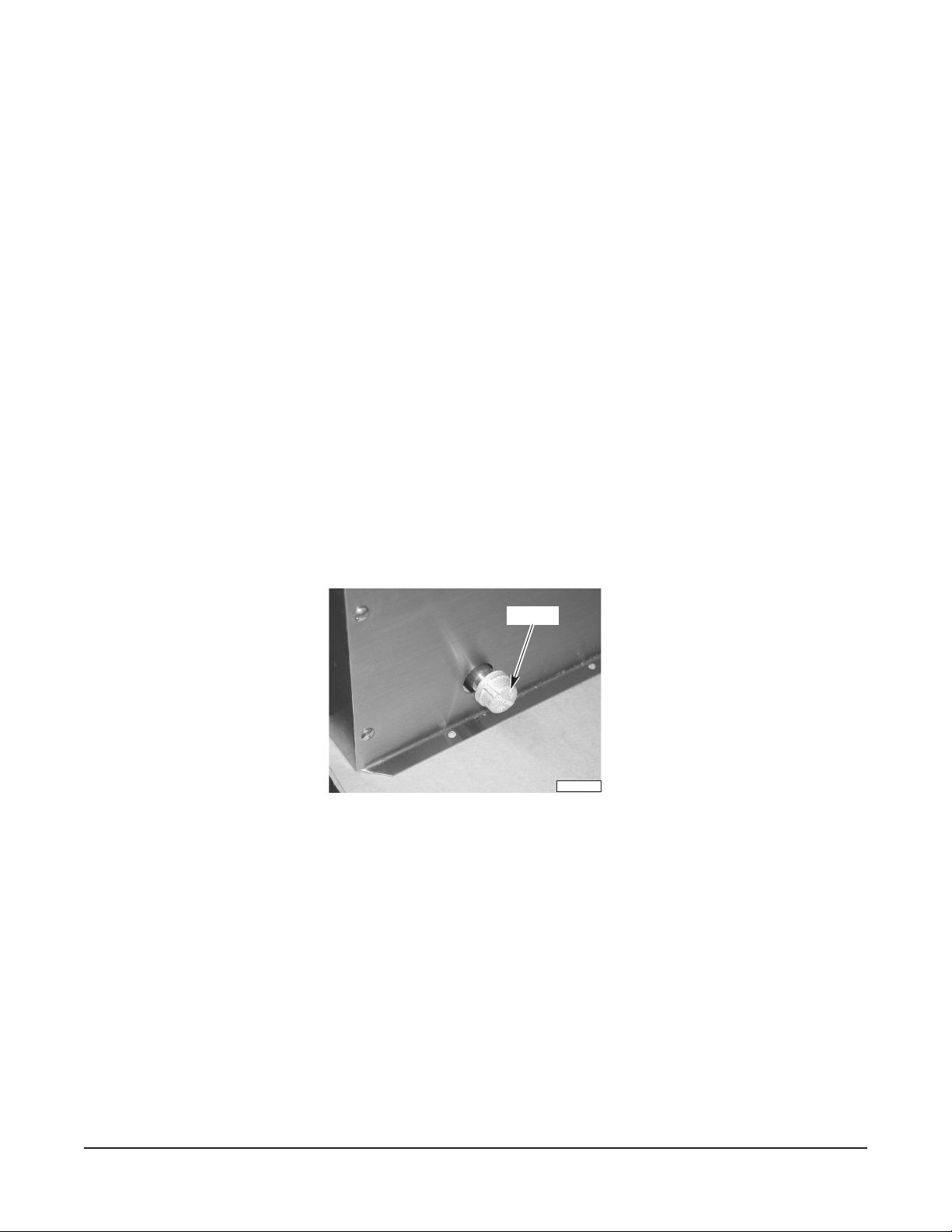
DRAIN CONNECTION
The outflow of warm water from the condenser coil can be plumbed to the prewash section of the
dishwasher or to customer's drain from the 1/2 inch external threaded pipe fitting on either the rear or
front of the condenser. Typically, the rear outflow fitting is used; however, if access to the rear of the
dishwasher is restricted, the plumbing line may be more easily installed in the front. In either case, the
1
alternate drain fitting, opposite the fitting being used, should be capped with the
/2 inch pipe cap,
provided (Fig. 4).
END CAP
PL-41574-1
Fig. 4
COLD WATER SUPPLY CONNECTION
3
The cold water supply line to the condenser must be a minimum of
/4 inch pipe. The inlet water supply
connection is located at the midline (front to back) below the louvered end of the condenser. Route
the incoming supply line behind the control box using the water supply piping and fittings supplied.
Install the piping and fittings according to Fig. 5 for left-to-right operation at the exit end; install
according to Fig. 6 for right-to-left operation at the exit end. For installations of the condenser at the
load end, use Fig. 5 for right-to-left operation; use Fig. 6 for left-to-right.
– 5 –
Page 6

sgnittiFdnagnipiPylppuSretaW
.oNtraP.ytQnoitpircseD
24-04-PF3elppiN
36-77-PF1 gnilpuoCgnicudeR
2892181evlaVllaB
1
/21x"1/8"
1
/2"
3
/4ot"1/2"
5152011reniartS
61-51-PF1woblE
01-14-PF1epiP
51-82-PF1gulPepiP
1
/
2
°09x"
1
/29x"
3
/4"
1
/2"
In either case, place the strainer at a 45° angle to allow removal of the clean-out plug to clean the
strainer.
Left-to-Right Operation Exit End Shown
BALL VALVE
REDUCING COUPLING (
Right-to-Left Operation Exit End Shown
PIPE PLUG
STRAINER
NIPPLE
INLET
PIPE (
ELBOW (
3
/
" to
4
Fig. 5
1
/
2
1
" X 9
1
/
")
2
/
")
2
3
/
")
ELBOW (
4
PIPE (
PIPE PLUG
1
/
")
2
NIPPLE
1
/
" X 9
2
3
/
")
4
INLET
PL-41572-1
PL-41573-1
STRAINER
REDUCING COUPLING (
Fig. 6
– 6 –
BALL VALVE
3
/
4
" to
1
/
")
2
Page 7

ELECTRICAL CONNECTIONS
WARNING: ELECTRICAL AND GROUNDING CONNECTIONS MUST COMPLY WITH APPLICABLE
PORTIONS OF THE NATIONAL ELECTRICAL CODE AND/OR OTHER LOCAL ELECTRICAL CODES.
WARNING: DISCONNECT THE ELECTRICAL POWER SUPPLY AND PLACE A TAG AT THE
DISCONNECT SWITCH INDICATING THAT YOU ARE WORKING ON THE CIRCUIT.
Refer to the electrical diagram inside the condenser control box.
Conduit is provided pre-wired from the condenser. A conduit fitting must be fastened to the hole
provided in the dishwasher control box. Remove the conduit nut from the conduit. Feed the wires from
the end of the conduit into the dishwasher control box. Tighten the conduit nut to the conduit fitting
inside the control box. Connect L1 and L2 on a single-phase condenser (connect L1, L2 and L3 on a
three-phase condenser) to the pump motor contactor labeled 1CON in the dishwasher control box.
Connect the gray wire to terminal 1 on terminal board 2TB. Connect the red wire to terminal 10 on
terminal board 2TB. Connect the pink wire to terminal 13 on terminal board 2TB. When connecting
the dishwasher electrical supply, allow sufficient amperage for the increase required by the addition
of the condenser motor:
ATADLACIRTCELE
esahP/ztreH/stloV)resnednoChcaE(spmArotoM
002– 1/06/0425.3
002– 3/06/0422.2
004– 3/06/0841.1
ehtgniylppustiucricehtfoyticapmaehtniesaercninawolladluohsnaicirtcelE
.)s(rotomrewolbresnednocehtfostnemeriuqerlanoitiddaehtrofwollaotrehsawhsid
CHECK MOTOR ROTATION (Three-Phase Machines)
The blower on any three-phase condenser must rotate in the direction of the arrow on the condenser
housing. Before placing the machine into service, check to verify correct rotation by observing the
condenser fan at the louvered end of the condenser.
If the blower does not rotate in the direction of the arrow on the condenser housing, DISCONNECT THE
ELECTRICAL POWER SUPPLY(IES) and interchange any two of the blower motor's incoming power
supply leads. Reconnect electrical power and verify that the blower rotates in the proper direction.
– 7 –
Page 8

SERVICE
If service is needed on this equipment, contact your local Hobart Service Office.
FORM 34703 (Sept. 2001) PRINTED IN U.S.A.
– 8 –
 Loading...