

Page 1

ASSEMBLY INSTRUCTIONS
VENT FAN CONTROL — KIT NO. 749907
This
Assembly Instruction
models and ML's only:
MODEL
AM14 ML-110976
AM14C ML-110977
AM14T ML-110973
AM14TC ML-110974
AM14F ML-110975
IMPORTANT: This kit must be installed only by an authorized Hobart-trained service technician.
This kit cannot be used on machines built with lower ML numbers. Check the data plate on the machine
to make sure the model number and ML number match one of the numbers above. If the model and
ML number do not match, do not continue with the assembly.
The Vent Fan Control Relay will switch an auxiliary vent fan (not supplied by Hobart): ON when the
machine is on and OFF when the machine is off. Power to operate the vent fan must be supplied
separately; the Vent Fan Control Relay provides switching only (up to 1.5 Amperes).
is to assemble a Vent Fan Control relay into the control box on the following
PART NO. NAME OF PART AMT.
749907 Vent Fan Control Kit (complete) . . . . . . . . . . . . . . . . . . . . . . . . 1
749636 Base Plate . . . . . . . . . . . . . . . . . . . . . . . . . . . . . . . . . . . . . . . . . 1
3
SC-071-11 Screw, 10 – 24 x
/8" Philips Head . . . . . . . . . . . . . . . . . . . . . . 4
WL-007-12 Lock Washer (for #10 screw) . . . . . . . . . . . . . . . . . . . . . . . . . . 4
87714-20-1 Relay . . . . . . . . . . . . . . . . . . . . . . . . . . . . . . . . . . . . . . . . . . . . . 1
3
SD-008-17 Drive Screw, 6 – 20 x
/8" Philips Head . . . . . . . . . . . . . . . . . . 2
289104-80 Lead Wire GRAY 2CR-B ~ 1T-24C . . . . . . . . . . . . . . . . . . . . . 1
289104-185 Lead Wire RED 2CR-A ~ 2TB / 6TB . . . . . . . . . . . . . . . . . . . . 1
289104-231 Lead Wire BLACK 2CR-5 ~ VFC1 . . . . . . . . . . . . . . . . . . . . . . 1
289104-232 Lead Wire BLACK 2CR-8 ~ VFC2 . . . . . . . . . . . . . . . . . . . . . . 1
83376 Wire Ties . . . . . . . . . . . . . . . . . . . . . . . . . . . . . . . . . . . . . . . . . . 2
438131-60 Warning Label . . . . . . . . . . . . . . . . . . . . . . . . . . . . . . . . . . . . . . 1
F-34566 Assembly Instructions . . . . . . . . . . . . . . . . . . . . . . . . . . . . . . . . 1
WARNING: ELECTRICAL AND GROUNDING CONNECTIONS MUST COMPLY WITH THE
APPLICABLE PORTIONS OF THE NATIONAL ELECTRICAL CODE AND/OR OTHER LOCAL
ELECTRICAL CODES.
NOTE: Models equipped with the Hobart built-in 13 kw Electric Booster already have the Base Plate
installed in the control box. Models equipped with Gas Heat are already equipped with the Vent Fan
Control Base Plate and Vent Fan Control Relay — and, therefore should not use this kit.
NOTE: Refer to the electrical diagram inside the control box.
701 S. RIDGE AVENUE
TROY, OHIO 45374-0001
937 332-3000
www.hobartcorp.com
FORM 34566 (Dec. 2000)
Page 2
MODELS AM14, AM14C, AM14T, AM14TC
4
4
4
WARNING: DISCONNECT ELECTRICAL POWER SUPPLY AND PLACE A TAG AT THE
DISCONNECT SWITCH TO INDICATE THAT YOU ARE WORKING ON THE CIRCUIT.
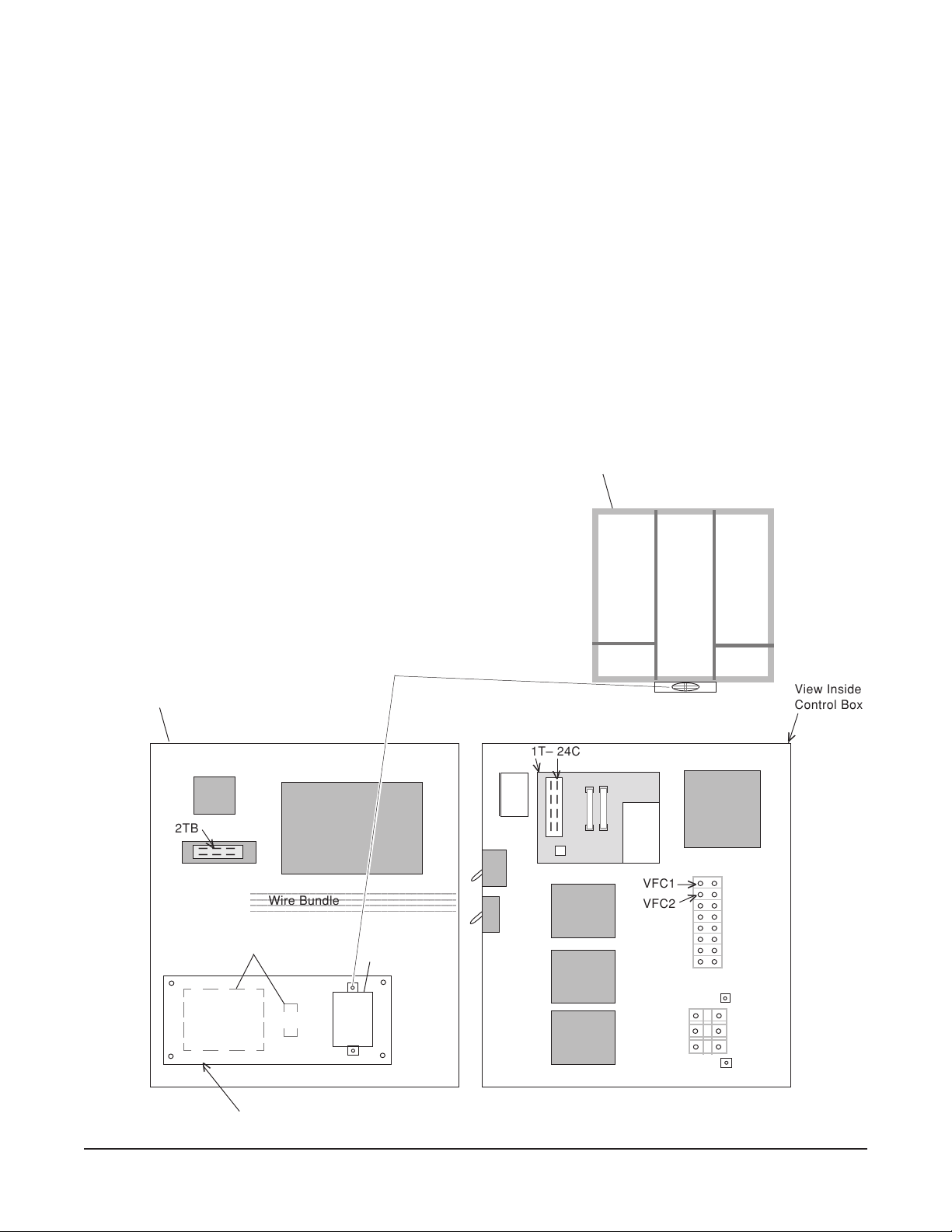
1. Open control box lid.
2. Locate the four standoffs on the lid and install the Base Plate with the 4 lock washers and 4 screws
provided. The two screw holes for mounting the Relay should be on the right (Fig. 1).
3. Assemble the Relay (2CR) to the Base Plate so the terminals face towards the wire bundle (Fig. 1).
Use the two screws, provided, to secure the Relay to the Base Plate.
4. Install the Red, Gray, and two Black lead wires per the wiring diagram. Make sure all wire
connections are fully inserted and tight. Relay 2CR terminal locations are shown in Fig. 1.
• Connect the Red Wire to 2CR-A and 2TB;
• Connect the Gray Wire to 2CR-B and 1T-24C;
• Connect the Black Wire to 2CR-5 and VFC1;
• Connect the Black Wire to 2CR-8 and VFC2; and,
• Install and secure all lead wires with the wire ties
provided.
5. After all wires are checked per the wiring diagram
and securely tied with the wire ties, close the control
box lid. Power up the dishwasher. Check for proper
operation. Relay is energized when machine is
powered up.
6. If Warning Label 438131-42 is used on the front of
the lid, replace with 438131-60.
Mounting Screw
Inside View of Lid
>
2TB
>
– – –
– – –
2345678901234567890123456789012123
2345678901234567890123456789012123
2345678901234567890123456789012123
Wire Bundle
13 kw Booster Board
and Fuse (optional)
>
Relay 2CR
>
>
1T– 24C
>
>
– – – –
– – – –
Relay 2CR
>
___
___
5
___
8
__
A
VFC1
VFC2
B
>
>
View Inside
Control Box
>
>
Base Plate
Fig. 1
– 2 –
Page 3

MODEL AM14F
12345678901234567890123456789012123
1
3
1
3
1
3
12345678901234567890123456789012123
WARNING: DISCONNECT ELECTRICAL POWER SUPPLY AND PLACE A TAG AT THE
DISCONNECT SWITCH TO INDICATE THAT YOU ARE WORKING ON THE CIRCUIT.
1. Open control box lid.
2. The Base Plate, screws and lock washers are not used. Refer to Fig. 2 for the mounting location
of the Relay.
3. Assemble the Relay (2CR) to the Relay Plate so the terminals face forwards (Fig. 2). Use the two
screws, provided, to secure the Relay to the Relay Plate.
4. Install the Red, Gray, and two Black lead wires per the wiring diagram. Make sure all wire
connections are fully inserted and tight.
• Connect the Red Wire to 2CR-A and 6TB;
• Connect the Gray Wire to 2CR-B and 1T-24C;
• Connect the Black Wire to 2CR-5 and VFC1;
• Connect the Black Wire to 2CR-8 and VFC2; and,
• Install and secure all lead wires with the wire ties
provided.
5. After all wires are checked per the wiring diagram
and securely tied with the wire ties, close the control
box lid. Power up the dishwasher. Check for proper
operation. Relay is energized when machine is
powered up.
6. If Warning Label 438131-42 is used on the front of
the lid, replace with 438131-60.
Mounting Screw
View Inside
Control Box
>
>
>
VFC1
VFC2
1T – 24C
>
– – – –
>
– – – –
Inside View of Lid
>
6TB
>
– – –
– – –
Relay 2CR
>
___
___
___
__
A
5
8
B
Relay Plate
234567890123456789012345678901212
234567890123456789012345678901212
234567890123456789012345678901212
Wire Bundle
13 kw Booster Board
and Fuse (optional)
>
>
>
Relay 2CR
>
Fig. 2
– 3 –
Page 4

NOTES
FORM 34566 (Dec. 2000) PRINTED IN U.S.A.
– 4 –
 Loading...