

Hobart 9OC24S Operation Manual
Revised 062574
Rev ised 022278
OPERATION, MAINTENANCE, AND OVERHAUL MANUAL
FOR
SELF-PROPELLED GENERATOR SET
MODE L N 0. 9OC24S
TM-240A
103073
SPECIFICATION NO. 5381A AND VARIATIONS
90KVA, 115/200-V AC, 400 tjZ, 3-PHASE
Manufactured by ,
MOTOR GENERATOR DIVISION
HOBART BROTHERS COMPANY
TROY, OH IO 45373
U.S.A.

SAFETY INSTRUCTIONS AND WARNINGS FOR ELECTRICAL POWER EQUIPMENT
ELECTRIC SHOCK can kill. Do not touch live electrical parts.
FUMES AND GASES can be fire and health hazards. Ventilate all fumes and exhaust gases to the outside.
ELECTRIC ARC FLASH can injure eyes, burn skin, cause equipment damage, and ignite combustible material. Do not
use power cables to break load and be sure tools don’t cause short circuits.
IMPROPER PHASE CONNECTION, PARALLELING, OR USE can damage this and attached equipment.
MOVING PARTS can cause serious injury. Keep clear of moving parts.
iMPORTANT - Protect yourself and others. Read and understand all the instructions in this Operating/Instruction
Manual before installing, operating, or servicing this equipment. Keep this manual available for future
use by all operators.
A. GENERAL
Equipment that supplies electrical power can cause serious injury or death, or damage to other equipment or
property, if the operator does not strictly observe all safety rules and take precautionary actions. Safe practices
have developed from past experience in the use of power source equipment. Certain of the practices below apply to
engine driven equipment.
6. SHOCK PREVENTION
Bare conductors, or terminals in the output circuit, or ungrounded, electrically-live equipment can fatally shock a
person. Have a competent electrician verify that the equipment is adequately grounded and learn what terminals
and parts are electrically HOT. Use proper safety clothing, procedures, and test equipment.
The electrical resistance of the body is decreased when wet, thus more easily permitting dangerous currents to flow
through it. When inspecting or servicing equipment, do not work in damp areas without being extremely careful.
Stand on dry rubber mat or dry wood, use insulating gloves that are effective when dampness or sweat cannot be
avoided. Keep your clothing dry and never work alone.
1. Installation and Grounding of Electrically Powered Equipment - Electrical equipment must be installed
and maintained in accordance with the National Electrical Code, ANSI/NFPA 70, and other applicable codes.
A power disconnect switch or circuit breaker must be located at the equipment. Check the nameplate for voltage,
frequency, and phase requirements. If only 3-phase power is available, connect any single-phase rated equipment to
only two wires of the 3-phase line. DO NOT CONNECT the equipment grounding conductor (lead) to the third live
wire of the 3-phase line, g this makes the eauipment frame electricallv
---
HOT, which can cause a fatal shock
--- ----
Be sure to connect the grounding lead, if supplied in a power line cable, to the grounded switch box or building
ground. If not provided, use a separate grounding lead. Be certain that the current (amperage) capacity of the
grounding lead will be adequate for the worst fault current situation. Refer to the National Electrical Code ANSI/
NFPA 70 for details. Do not remove plug ground prongs. Use correct mating receptacles.
2. Output Cables and Terminals - Inspect cables often for damage to the insulation and the connectors. Replace
or repair cracked or worn cables immediately. Do not overload cables. Do not touch output terminal while equip-
ment is energized.
Instruction 910082
Nov 16182 Revised
Page 1
,--
3. Service and Maintenance - This equipment must be maintained in good electrical and mechanical condition
to avoid hazards stemming from disrepair. Report any equipment defect or safety hazard to your supervisor and
discontinue use of the equipment until its safety has been assured. Repairs should be made by qualified personnel
only. Shut OFF all power at the disconnecting switch or line breaker before inspecting or servicing the equipment.
Lock switch OPEN (or remove line fuses) so that power cannot be turned ON accidentally. Disconnect power to
equipment if it is out of service. If troubleshooting must be done with the unit energized, have present another person trained in turning off the equipment and providing or calling for first aid.
C. FIRE AND EXPLOSION PREVENTION
Fire and explosion are caused by electrical short circuits, combustible material near engine exhaust piping, misuse
of batteries and fuel, or unsafe operating or fueling conditions.
1.
Electrical Short Circuits and Overloads - Overloaded or shorted equipment can become hot enough to cause
fires either by self destruction or causing nearby combustibles to ignite. Provide primary input protection to remove short circuited or heavily overloaded equipment from the line.
2. Battery - Batteries may explode and/or give off flammable hydrogen gas. The acid and arcing from a ruptured
battery can cause fires and additional failures. When servicing, do not smoke, causing sparking, or use open flame
near the battery.
3. Enqine Fuel
- Use only approved fuel container or fueling system. Fires and explosions can occur if the fuel
tank is not grounded prior to and during fuel transfer. Shut unit DOWN before removing fuel tank cap. Do not
completely fill tank. Heat from the equipment may cause fuel expansion overflow. Remove all spilled fuel immediately including any that penetrates the unit. After cleanup, open equipment doors and blow fumes away with
compressed air.
D. TOXIC FUME PREVENTION
Carbon Monoxide - Engine exhaust fumes can kill and cause health problems. Pipe or vent the exhaust fumes to a
suitable exhaust duct or outdoors. Never locate engine exhausts near intake ducts or air conditioners.
E. BODILY INJURY PREVENTION
Serious injury can result from contact with fans, belts, and pulleys inside the equipment. Shut DOWN equipment
for inspection and routine maintenance. When equipment is in operation use extreme care in doing necessary
troubleshooting and adjustment.
F. MEDICAL AND FIRST AID TREATMENT
First aid facilities and a qualified first aid person should be available for each shift for immediate treatment of all
injury victims. Electric shock victims should be checked by a physician and taken to a hospital immediately if any
abnormal signs are observed.
EMERGENCY FIRST AID
Call physician immediately. Seek additional assistance and use First Aid techniques recommended
by American Red Cross until medical help arrives.
IF BREATHING IS DIFFICULT, give oxygen, if available, and have victim lie down. FOR ELECTRICAL SHOCK, turn off power. Remove victim; if not breathing, begin artificial respiration,
preferably mouth-to-mouth. If no detectable pulse, begin external heart massage. Call Emergency
Rescue Squad immediately.
G. EQUIPMENT PRECAUTIONARY LABELS
Inspect all precautionary labels on the equipment monthly. Order and replace all labels that cannot be easily read.
Page 2
Instruction 910082
Revised Nov 16/82
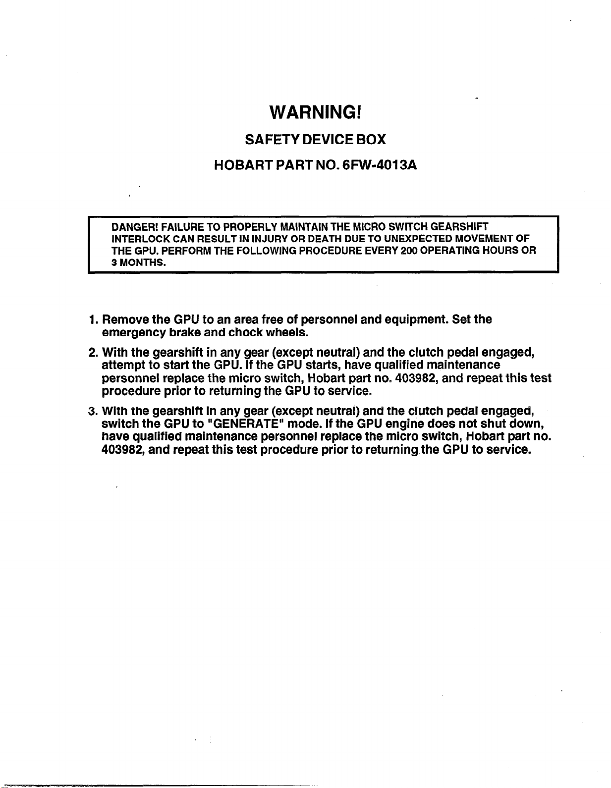
WARNING!
SAFETY DEVICE BOX
HOBART PART NO. 6FW-4013A
DANGER! FAILURE TO PROPERLY MAINTAIN THE MICRO SWITCH GEARSHIFT
INTERLOCK CAN RESULT IN INJURY OR DEATH DUE TO UNEXPECTED MOVEMENT OF
THE GPU. PERFORM THE FOLLOWING PROCEDURE EVERY 200 OPERATING HOURS OR
3 MONTHS.
1. Remove the GPU to an area free of personnel and equipment. Set the
emergency brake and chock wheels.
2. With the gearshift in any gear (except neutral) and the clutch pedal engaged,
attempt to start the GPU. If the GPU starts, have qualified maintenance
personnel replace the micro switch, Hobart part no. 403982, and repeat this test
procedure prior to returning the GPU to service.
3. With the gearshift in any gear (except neutral) and the clutch pedal engaged,
switch the GPU to “GENERATE” mode. If the GPU engine does not shut down,
have qualified maintenance personnel replace the micro switch, Hobart part no.
403982, and repeat this test procedure prior to returning the GPU to service.


rOi?IAR~
e
a
‘0
b . @ ,,R
EMOTOR GENERATOR DIVISION
QD
:
z
HOBART BROTHERS COMPANY
OPERATION, MAINTENANCE, AND OVERHAUL MANUAL, TM-240A
SELF-PROPELLED GENERATOR SET, SPEC. NO. 5381A
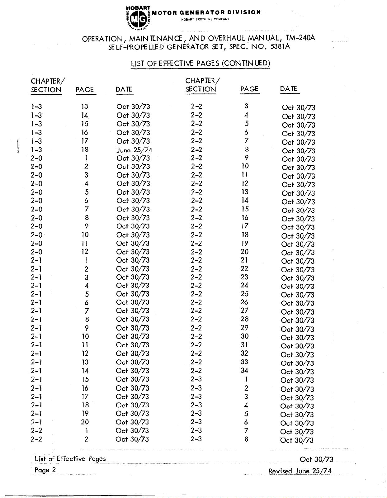
LIST OF EFFECTIVE PAGES
CHAPTER/
SECTION
Introduction
introduction
In troducticn
Introduction
Introduction
Introduction
,
List of
Effective
Pages
Contents
i
Con tents
Con tents
Con tents
Contents
Contents
Contents
Contents
Contents
Contents
1
1-O
1-O
1-o ’
1-O
I
1-o
1-o
1-o
1-o
l-l
1-l
l-l
1-l
l-l
l-l
l-l
l-l
l-l
l-l
PAGE
1
2
3
4
5
6
1 thru 6
DATE
act 30/73
Ott 30/73
Ott 30/73
Ott 30/73
act 30/73
Ott 30/73
Feb 22/78
1 June 25/74
2
Ott 30/73
3 act 30/73
4
5
Ott 30/73
Ott 30/73
6 Ott 30/73
7
Ott 30/73
8 Ott 30/73
9
10
June 25/74
Ott 30/73
1 Ott 30/73
2
3
Ott 30/73
Ott 30/73
4 June 25/74
5
6
7
8
Ott 30/73
act 30/73
Ott 30/73
act 30/73
1 act 30/73
2
3
4
5
6
7
8
9
10
Ott 30/73
Ott 30/73
Ott 30/73
act 30/73
Ott 30/73
Ott 30/73
act 30/73
Ott 30/73
Ott 30/73
CHAPTER/
SECTION
PAGE
l-l
l-l
l-l
l-l
l-l
l-l
l-l
l-l
l-l
l-l
l-l
l-l 22
l-l
1-l
l-l
l-l 26
l-l
l-l
l-l
1-l
1-l
l-l
l-2
l-2
l-2
l-2
1-2
l-2
l-3
l-3
l-3
l-3
l-3
l-3
l-3
l-3
l-3
l-3
l-3 _
l-3
11
12
13
14
15
16
17
18
19
20
21
23
24
25
27
28
29
30
31
32
2
3
4
5
6
2
3
4
5
6
7
8
9
10
11
12
1
1
DATE
Ott 30/73
act 30/73
Ott 30/73
Ott 30/73
Ott 30/73
Ott 30/73
Ott 30/73
Ott 30/73
Ott 30/73
act 30/73
Ott 30/73
act 30/73
Ott 30/73
Ott 30/73
Ott 30/73
Ott 30/73
Ott 30/73
Ott 30/73
act 30/73
Ott 30/73
June 25/74
Ott 30/73
Ott 30/73
Ott 30/73
Ott 30/73
Ott 30/73
act 30/73
Ott 30/73
act 30/73
Ott 30/73
Ott 30/73
Ott 30/73
Ott 30/73
Ott 30/73
act 30/73
act 30/73
Ott 30/73
Ott 30/73
act 30/73
June 25/74
..~ Ju_ne 25/74 Revised
Feb 22178 ‘Rev ised
FOBAl?:
e
a
;
b . B ,&
~MOTOR GENERATOR DIVISION
QD
5
t
HOBART BROTHERS COMPANY
OPERATION, MAINTENANCE, AND OVERHAUL MANUAL, TM-240A
SELF-PROPELLED GENERATOR SET, SPEC. NO. 5381A
LIST OF EFFECTIVE PAGES (CON TIN UED)
CHAPTER/
SECTION
l-3
l-3
l-3
l-3
l-3
l-3
I
2-o
2-o
2-o
2-o
2-o
2-o
2-o
2-o
2-o
2-o
2-o
2-o
2-l
2-l
2-l
2-l
2-l
2-l
2-l
2-l
2-l
2-l
2-l
2-l
2-l
2-l
2-l
.2-l
2-l
2-l
2-l
2-l
2-2
2-2
PAGE
DAlE
13 act 30/73
14,
act 30/73
15 Ott 30/73
16 act 30/73
17 Ott 30/73
18
1
2
June 25/i4
act 30/73
Ott 30/73
3 act 30/73
4
Ott 30/73
5 Ott 30/73
6 Ott 30/73 2-2
7
8
Ott 30/73
Ott 30/73
9 act 30/73
10 act 30/73
11
Ott 30/73 2-2
12 act 30/73
1
2
3
4
5
6
7
8
9
10
11
12
13
14
15
16
Ott 30/73 2-2
act 30/73 2-2
act 30/73
act 30/73 2-2
act 30/73
act 30/73
act 30/73
act 30/73
act 30/73 2-2
act 30/73 2-2
act 30/73
act 30/73
act 30/73
act 30/73 2-2
act 30/73
act 30/73
17 act 30/73
18 act 30/73
19 act 30/73
20
1
2
act 30/73
Ott 30/73
Ott 30/73
CHAPTER/
SECTION
2-2
2-2
2-2
2-2
2-2
2-2
2-2
2-2
2-2
2-2
2-2
2-2
2-2
2-2
2-2
2-2
2-2
2-2
2-2
2-2
2-2
2-2
2-2
2-2
2-3
2-3
2-3
2-3
2-3
2-3
2-3
2-3
PAGE
3
4
5
6
7
8
9
10
11
12
13
14
15
16
17
18
19
20
21
22
23
24
25
26
27
28
29
30
31
32
33
34
1
2
3
4
5
6
7
8
DAIE
Ott 30/73
Ott 30/73
Ott 30/73
Ott 30/73
Ott 30/73
act 30/73
Ott 30/73
Ott 30/73
Ott 30/73
Ott 30/73
Ott 30/73
Ott 30/73
act 30/73
act 30/73
Ott 30/73
Ott 30/73
Ott 30/73
Ott 30/73
Ott 30/73
Ott 30/73
Ott 30/73
Ott 30/73
Ott 30/73
act 30/73
act 3op3
act 30/73
act 30/73
act 30/73
act 30/73
act 30/73
act 30/73
act 30/73
Ott 30/73
Ott 30/73
Ott 30/73
act 30/73
act 30/73
Ott 30/73
act 30/73
‘Ott 30/73
List bf Effective Pages
_ -
Page 2
_ ~~ .-.-GM .xm ..~ ‘
Revised June 25/‘?‘9
.--.-..~...-~.--.-- ..-
FOBART
B
z
“c
QB
48
gMOTOR GENERATOR DIVISION
0. B.0
c
‘Q+
2
HOBART BRCJTHERS COMPANY
OPERATION, MAINTENANCE. AND OVERHAUL MANUAL. TM-240A
SELFlPROPELlED GENiRATOR SET, SPEC. NO. 53&A
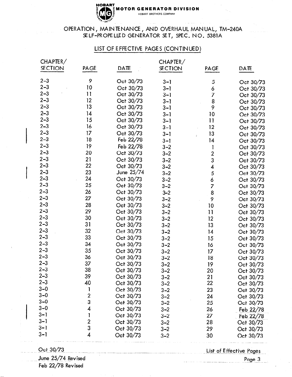
LIST OF EFFECTIVE PAGES (CONTINUED)
CHAPTER/
SECTION
PAGE
2-3
2-3
2-3 ’
2-3
2-3
2-3
2-3
2-3
2-3
2-3
2-3
2-3
2-3
10
11
12
13
14
15
16
17
18
19
20
21
2-3 22
2-3
2-3
2-3
2-3
2-3
2-3
2-3
2-3
2-3
2-3
2-3
2-3
2-3
2-3
2-3
2-3
2-3
2-3
23
24
25
26
27
28
29
30
31
32
33
34
35
36
37
38
39
40
3-o
3-o
3-o
3-o
3-l
3-l
3-l
3-l
4
2
3
4
2
3
9
1
1
DATE
Ott 30/73
act 30/73
Ott 30/73
Ott 30/73
Ott 30/73
act 30/73
Ott 30/73
Ott 30/73
Ott 30/73
Feb 22/78
Feb 22/78
Ott 30/73
Ott 30/73
Ott 30/73
June 25/74
Ott 30/73
act 30/73
act 30/73
act 30/73
Ott 30/73
Ott 30/73
Ott 30/73
Ott 30/73
Ott 30/73
Ott 30/73
Ott 30/73
Ott 30/73
act 30/73
act 30/73
Ott 30/73
Ott 30/73
Ott 30/73
Ott 30/73
Ott 30/73
Ott 30/73
act 30/73
act 30/73
act 30/73
Ott 30/73
act 30/73
~. .~.
CHAPTER/
SECTION
PAGE
3-l
3-l 6
3-l
3-l
3-l
3-l
3-l
3-l
3-l
3-l
3-2
3-2 2
3-2 3
3-2 4
3-2
3-2
3-2 7
3-2
3-2
3-2
3-2
3-2
3-2
3-2
3-2
3-2
3-2
3-2
3-2
3-2
3-2
3-2
3-2
3-2
3-2
3-2
3-2
3-2
3-2
3-2
10
11
12
13
14
10
11
12
13
14
15
16
17
18
19
20
21
22
23
24
25
26
27
28
29
30
5
6
8
9
5
7
8
9
1
DATE
Ott 30/73
act 30/73
Ott 30/73
Ott 30/73
Ott 30/73
Ott 30/73
Ott 30/73
Ott 30/73
Ott 30/73
Ott 30/73
Ott 30/73
Ott 30/73
Ott 30/73
Ott 30/73
Ott 30/73
Ott 30/73
act 30/73
Ott 30/73
Ott 30/73
Ott 30/73
act 30/73
Ott 30/73
Ott 30/73
Ott 30/73
Ott 30/73
Ott 30/73
Ott 30/73
Ott 30/73
act 30/73
Ott 30/73
Ott 30/73
Ott 30/73
Ott 30/73
act 30/73
Ott 30/73
OctW73.
June .?5n4 Rev ised
Feb 22/?8 Revised
j&t. @Ffective Pages
Page 3

HOBART
E
z
“0
QD
b . I ,,d
~MOTOR GENERATOR DIVISION
z
5
HOBART BROTHERS COMPANY
OF’ERATION, MAINTENANCE, AND OVERHAUL MANUAL, TM-240A
SELF-PROPELLED GENERATOR SET, SPEC. NO. 5381A
LIST OF EFFECTIVE PAGES (CON TIN UED)
CHAPTER/
SECTION
4-o
4-o
4-l
4-l
4-l
4-l
4-l
4-l
4-l
4-l
4-l
4-l
4-l
4-l
4-l
4-l
4-2
4-2
4-2
4-2
5-o
5-o
5-l
5-l
5-l
5-l
5-l
5-l
5-l
5-l
5-2
5-2
6-O
6-O
6-l
6-l
6-l
6-l
6-l
6-l
PAGE DATE
1
?
’ 1
2
act
act
Ott
Ott
3 Ott
4 Ott
5
6
7
8
9
10
Ott
Ott
Ott
Ott
Ott
Ott
11 Ott
12
Ott
13 act
14
1
2
3
4
1
2
1
2
3
4
5
6
7
8
1
2
1
2
1
2
3
4
5
6
Ott
Ott
act
act
Ott
act
Ott
act
Ott
Ott
Ott
Ott
Ott
Ott
Ott
Ott
Ott
Ott
Ott
act
Ott
Ott
Ott
Ott
Ott
30/73
30/73
30/73
30/73
30/73
30/73
30/73
30/73
30/73
30/73
30/73
30/73
30/73
30/73
30/73
30/73
30/73
30/73
30/73
30/73
30/73
30/73
30/73
30/73
30/73
30/73
30/73
30/73
30/73
30/73
30/73
30/73
30/73
30/73
30/73
30/73
30/73
30/73
30/73
30/73
CHAPTER/
SECTION
6-l
6-l
6-l
6-l
6-l
6-l
6-l
6-l
6-l
6-l
6-l
6-l
6-l
6-l
6-l
6-l
6-l
6-l
6-2
6-2
7-o
7-o
7-o
7-o
7-l
7-l
7-l
7-l
7-2
7-2
7-2
7-2
7-2
7-2
7-2
7-2
7-3
7-3
7-3
7-3
PAGE DATE
7
8
9
10
11
12
13
14’
15
16
17
18
19
20
21
22
23
24
1
2
1
2
3
Ott 30/73
act 30/73
Ott 30/73
Ott 30/73
Ott 30/73
Ott 30/73
Ott 30/73
Ott 30/73
act 30/73
Ott 30/73
act 30/73
Ott 30/73
Ott 30/73
Ott 30/73
Ott 30/73
Feb 22/Z-
Fe&$!78
Ott 30/73
Ott 30/73
Ott 30/73
Ott 30/73
June 25/74
June 25/74
4 Ott 30/73
1
2
Ott 30/73
Ott 30/73
3 Ott 30/73
4
1
2
3
4
5
6
7
8
1
2
3
4
Ott 30/73
Ott 30/73
Ott 30/73
act 30/73
Ott 30/73
Ott 30/73
Ott 30/73
June 25/74
June 25/74
Ott 30/73
Ott 30/73
Ott 30/73
‘Ott 30/73
List of Effective Pages
Page 4
Ott 30/73
Revised J.une_25/?4~.
Revised Feb 22/78
FOBART
e
a
3
4k
OPERATION, MAINTENANCE, AND OVERHAUL MANUAL, TM-240A
SELF-PROPELLED GENERATOR SET, SPEC. NO. 5381A
:MOTOR GENERATOR DIVISION
:
z
QB
4.B,&
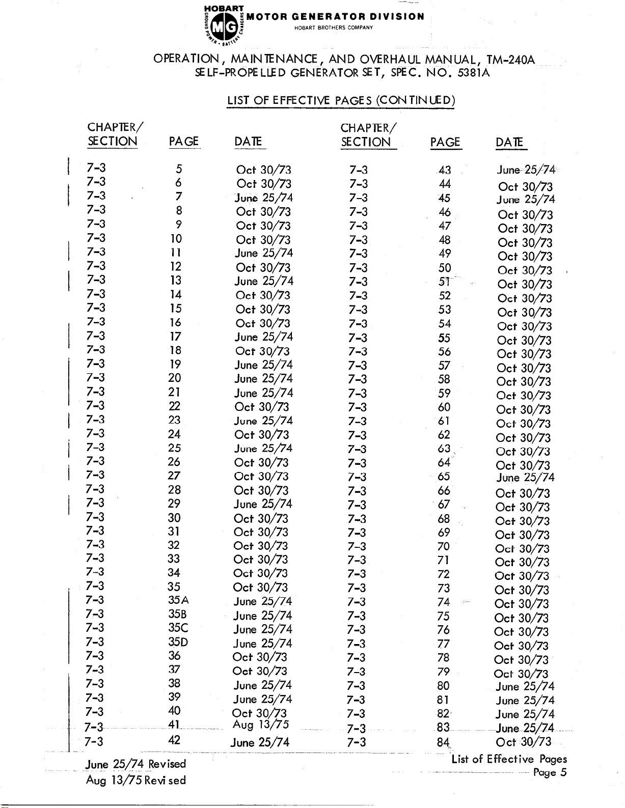
LIST OF EFFECTIVE PAGES (CON TIN UEDI
HOBART BRCJTHERS COMw.NY
CHAPlER/
SECTlOti
7-3
I
7-3
7-3 (
I
7-3
7-3
7-3 7-3
I
7-3
7-3
I
7-3
7-3
7-3
I
7-3
I
7-3
p 7-3
7-3
7-3
7-3
7-3
I
7-3
~
7-3
1
7-3 7-3
i
7-3
7-3 ’
I
7-3
7-3
7-3
7-3
7-3
7-3 7-3
I
7-3
7-3
7-3
7-3
7-3
7-3
7-3
7-3
7-3.
7-3
June ?5/74 Revised
Aug 13/75 Revi sed
PAGE
5
6
7
8
9
10
11
12
13
14
15
16
17 June 25/74
18
19
20
21
22
23
24
25 June 25p4
26
27
28
29 June 25/74
30
31
32
33
34
35
35A
35B
35c
35D
36
37
38
39
40
.41-..~-
42
DAlE
Ott 30/73
Ott 30/73
June 25p4
Ott 30/73
Ott 30/73
Ott 30/73
June 25/74
Ott 30/73
June 25/74
Ott 30/73
Ott 30/73
Ott 30/73
act 30/73
June 25/74
June 25/74
June 25/74
Ott 30/73
June 25/74
Ott 30/73
act 30/73
act 30/73
Ott 30/73
Ott 30/73
Ott 30/73
Ott 30/73
Ott 30/73
act 30/73
Ott 30/73
June 25/74
June 25/74
June 25/74
June 25/74
Ott 30/73
Ott 30/73
June 25/74
June 25/74
act 30/73
Aug 13/75
June 25/74
CHAP7ER/
SECTION
7-3
7-3
7-3
7-3
7-3
7-3
7-3
7-3
7-3
7-3
7-3
7-3
7-3
7-3
7-3
7-3
7-3
7-3
7-3
7-3
7-3
7-3
7-3
7-3
7-3
7-3
7-3
7-3
7-3
7-3
7-3
7-3
7-3
7-3
7-3
7-3
7-3
7-3
7-3
7-3
7-3
7-3
PAGE
43
44
45
46
47
48
49
50
y--
52
53
54
55
56
57
58
59
60
61
62
63 .,
64‘
65
66
67
68
69
70
71
72
73
74
75
76
77
78
79
80
81
82)
83
84,
List of Effective Pages
DAIE
June- 25174
Ott 30/73
June 25/74
Ott 30/73
Ott 30/73
Ott 30/73
Ott 30/73
Ott 30/73
Ott 30/73
Ott 30/73
Ott 30/73
act 30/73
Ott 30/73
Ott 30/73
Ott 30/73
Ott 30/73
Ott 30/73
Ott 30/73
Ott 30/73
Ott 30/73
Ott 30/73
act 30/73
June 25/74
Ott 30/73
act 30/73
Ott 30/73
Ott 30/73
Ott 30/73
Ott 30/73
Ott 30/73
Ott 30/73
Ott 30/73
Ott 30/73
Ott 30/73
Ott 30/73
Ott 30/73
Ott 30/73
June 25/74
June 25/74
June 25/74
June 25174
Ott 30/73
~~~ -- Page 5
CHAPTE I?/
SECTION
FOBART
I
z
“a
b. s,,+e
iMOTOR GENERATOR DIVISION
QD
a
2
HOBART BROTHERS CCIMPANY
OARATION, MAINTENANCE, AND OVERHAUL MANUAL, TM-240A
SELF-PROPELLED GENERATOR SET, SPECS. NO. 5381A
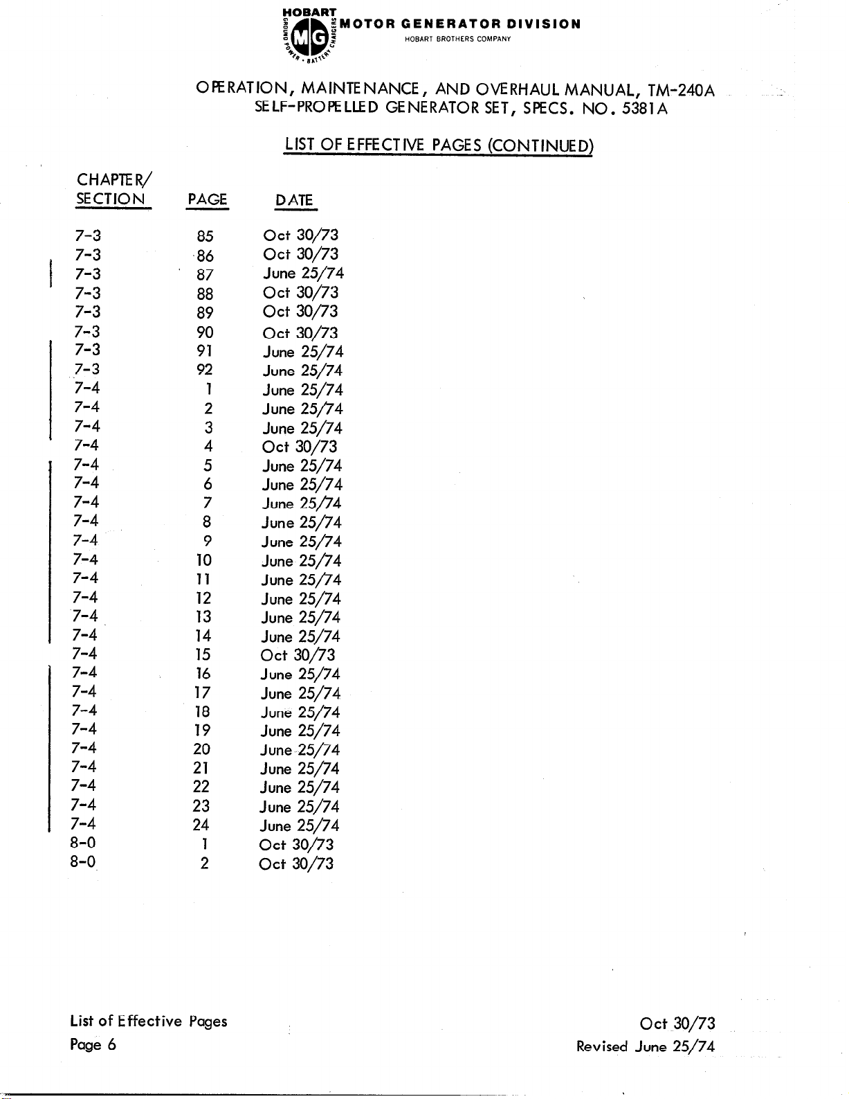
LIST OF EFFECTIVE PAGES (CONTINUED)
PAGE
D ATE
7-3
7-3
7-3
I
7-3
7-3
7-3
7-3
,7-3
7-4
7-4
7-4
’ 7-4
, 7-4
7-4
7-4
7-4
7-4
7-4
7-4
7-4
‘7-4
7-4
7-4
7-4
7-4
7-4
7-4
7-4
7-4
7-4
7-4
7-4
8-O
8-O
85
,86
87
88
89
90
91
92
5
6
7
8
9
10
11
12
13
14
15
16
17
18
19
20
21
22
23
24
1
2
2
3
4
1
Ott 30/73
Ott 30/73
June 25/74
Ott 30/73
Ott 30/73
Ott 30/73
June 25/74
June 25/74
June 25/74
June 25p4
June 25/74
Ott 30/73
June 25/74
June 25/74
June 25n4
June 25/74
June 25/74
June 25/74
June 25/74
June 25/74
June 25/74
June 25/74
act 30/73
June 25/74
June 25/74
June 25/74
June 25/74
June 25/74
June 25/74
June 25/74
June 25/74
June 25/74
Ott 30/73
Ott 30/73
List of Effective Pages
Page 6
act 30/73
Revised June 25/74
FOBART
I
::
“c
b. &*
;MOTOR GENERATOR DIVISION
QD
2
2
HOBART BROTHERS COMPANY
OPERATION, MAINTENANCE, AND OVERHAUL MAN UAL, TM-240A
SELF-PROPELLED GENERATOR SET, SPEC. NO. 5381A
INTRODUCTION
1. Genera I
The Introduction has been relocated to the front of the manual because we wish it to
be noticed and read first.
It has also been expanded in an attempt to give the reader
a better understanding of the manual and to make it more helpful and easier to use.
If you expect the manual to be useful to you, please read the introduction.
2.
scope
The manual contains descriptive,
maintenance, trouble shooting and overhaul information for a basic 400-Hertz, generator set and its different optional Variations.
qualified information throughout the manual will apply to the basic set and all variations.
identified as such. An explanation of “variations”
Any information which applies only to a specific variation will be qualified and
and how to identify all generator
sets is given in the Description, Chapter/Section l-l (Chapter 1, Section 1).
3. P
urpose
The manual’s purpose is to provide information and instructions to experienced operators,
electricians, and mechanics who have never seen or operated this generator set.
the intent of the manual to guide and assist operators and maintenance personnel in the
proper use and maintenance of the equipment.
4. Contents
Immediately following the Introduction is a List of Effective Pages which lists each
page in the manual by its Chapter/Section, and page number. Directly opposite
each page number listing is a date which indicates whether the page is original or
revised.
A complete Table of Contents appears next in sequence. It contains a list of all
Chapters, Sections, and the principal paragraph titles within each Section. The location of each listing is identified by Chapter/Section and page number. A complete
list of illustrations with their locations is located at the end of the Table of Contents.
Un-
G
It is
The main text of the manual is divided into eight Chapters as follows:
Chapter 1. Description/Operation
Chapter 2. Servicing
Chapter 3. Trouble Shooting
Chapter 4. RemovaI/lnstaI laticn
Chapter 5.
Repairs
act 30/73 Introduction
~~~~ Page 1
fOBART
8
z
“c
48
;MOTOR GENERATOR DIVISION
2
z
QQ
4. BL,I’La
HOEIART BROTHERS COMPANY
OPERATION, MAINTENANCE, AND OVERHAUL MANUAL, TM-240A
SELF-PROPELLED GENERATOR SET, SPEC. NO. 5381A
Chapter 6. Overhaul
Chapter 7.
Chapter 8.
II lustrated Parts List
Manufacturer’s Literature
Each Chapter is divided into as many Sections as necessary. Sections are always referred
to by a combination Chapter/Section number. Example, 2-3 refers to Chapter 2, Section
3.
5. Format
A. Paragraphing and Out I in ing
The material within each Section is divided into main subjects with applicable
paragraph headings and subheadings as required. This method not only helps keep
information closely knit, but provides a means of identifying material for reference
purposes.
For example, a portion of the Description Section might logically follow
this arrange men t and paragraph ing :
1. Control Box
A. Interior Panel
(1) Protective devices
(a) Over load relay
(2) Con tactors
Page N umber ing
B.
Page numbers do not run consecutively throughout the manual. Each page is
identified by the Chapter/Section number in which it appears, and by a page
number within the Chapter/Section. Therefore the first page in each Section is
page 1.
These identifying numbers appear in the lower, outside corner of each
page. Each page also bears a date located in the corner opposite the page number.
This date is either that of original issue, or of the latest revision. Any revision
to the original text is identified by a heavy black line in the left-hand margin.
Illustrations follow a numbering system similar to page numbering. The first
Figure in each Section is Figure 1.
6. How to Use the Manual
A. General
There has always been, and probably always will be, some disagreement between
writers, users-,-specification writers, and others, regarding all phases of manual
Introduction
Page 2
.-~o~t.~o[~~
FOBART
I
::
“c
B . LI ,,+*
;MOTOR GENERATOR DIVISION
:
z
QQ
HOBART BROTHERS COMPANY
OPERATION, MAINTENANCE, AND OVERHAUL MANUAL, TM-240A
SELF-PROPELLED GENERATOR SET, SPEC. NO. 5381A
preparation and how the manual-can best serve the needs of the user.
It is of
course impossible to completely satisfy al I concerned.
This manual follows the format, rules and style proposed by, and generally accepted
by members of the Air Transport Association.
grouped to help the user locate it quickly.
In so far as possible, information is
All tables, charts, diagrams, etc., as
well as illustrations, are identified by Figure Number (i.e., Fig. 2) to avoid con-
’ fusion.
How to Locate Information
B.
Even if you have read the manual completely and thoroughly, the easiest and quickest way to locate information is by using the Table of Contents. In addition to the
complete Table of Contents in the front of the manual, each Chapter has its own
Table of Contents and List of Illustrations.
(1) Table of Contents
The complete Table of Contents is only five pages long 9 Even if the user has
no idea where a certain bit of information is located, the general location
can be quickly found by running through the Table of Contents. For example,
some adjustment information is needed.
A quick look at the Table of Contents
indicates that “Adjustment/Test” information is located in Chapter/Section 2-3
(Chapter 2, Section 3).
If the specific adjustment being sought is not listed
in the main Table of Contents, turn to Chapter 2 and look in its Table of Con-
tents under “Adiustment/Test” where each adjustment is listed with the page
number location.
, (2) List of Illustrations
Ott 30/73
A complete List of Illustrations follows the Table of Contents and includes the
title, figure number, and Chapter/Section, with page number location of all
illustrations contained in the manual.
Locate the appropriate title in the
List of Illustrations, then turn to the Chapter/Section and page number indicated.
It should be noted here that ALL electrical connection diagrams are located
in Chapter 5, Repair.
(3) References
To avoid repetition and lengthy explanations, references to other material are
used throughout the manual. Both material in the text and illustrations may be
referred to in order to clarify or expand information and instructions. Portions
of the text are referred to by identifying the paragraph in which referenced
material may be found. A reference to other material would be in order right
here by referring to paragraphing information contained in paragraph 5, A
Introduction
FOBART
s
t
“c
‘I;
OPERATION, MAINTENANCE, AND OVERHAUL MANUAL, TM-240A
SELF-PROPELLED GENERATOR SET, SPEC. NO. 5381A
;MOTOR GENERATOR DIVISION
z
z
QQ
Q. BL,+e
HOBART BROTHERS COMPANY
above .
the reference, only the paragraph identification is given.
Example:
When referenced material is located in another Chapter/Section, both the
Chapter/Section number and the paragraph identification are given.
Example :
Components shown in illustrations and illustrations themse Ives are referenced
in a similar manner. When this type reference is made, the item number of
the part and the Figure number in which it appears are given.
Example:
When referenced material is located in the same Chapter/Section as
(Ref. Para.
the same Chapter/Section.
(Ref. 1-2, Para.
Chapter/Section l-2, and identified by paragraph 1, A.
1, A) means the material is to be found in paragraph 1, A, of
1, A) means that the referenced material is located in
(Ref. 2, Fig. 3) f re ers to item number 2 which appears in illustration Figure
3 of the same Chapter/Section.
When the referenced Figure appears in another Chapter/Section, the reference
will include the Chapter/Section number.
Example :
(Ref. 2-3; 1, Fig.
see item 1, in Figure 4.
Once a Figure number reference has been established for a series of instructional
steps, the Figure number is not repeated. Only the item numbers of parts involved are referenced.
For example, an instruction might appear like this: “Loosen screw (2, Fig. 6),
slide out connector (4), and remove brush (6)“.
When an item is referenced without a figure number, it will always apply to the
last preceding Figure number mentioned in the text.
NOTE:
The word “See” may appear in some references, as (See Fig. 2). It
means exactly the same thing as “Ref. “, however, its ,usage seems a
little more direct and definite.
4) tel Is the user to refer to Chapter/Section 2-3, and to
Introduction
page 4
Ott 30/73
POBARI
e
s
“0
% . B ,J
zMOTOR GENERATOR DIVISION
P
2
QQ
HOBART BROTHERS COMPANY
OPERATION, MAINTENANCE , AND OVERHAUL MAN UAL, TM-240A
SELF-PROPELLED GENERATOR SET, SPEC. NO. 5381A
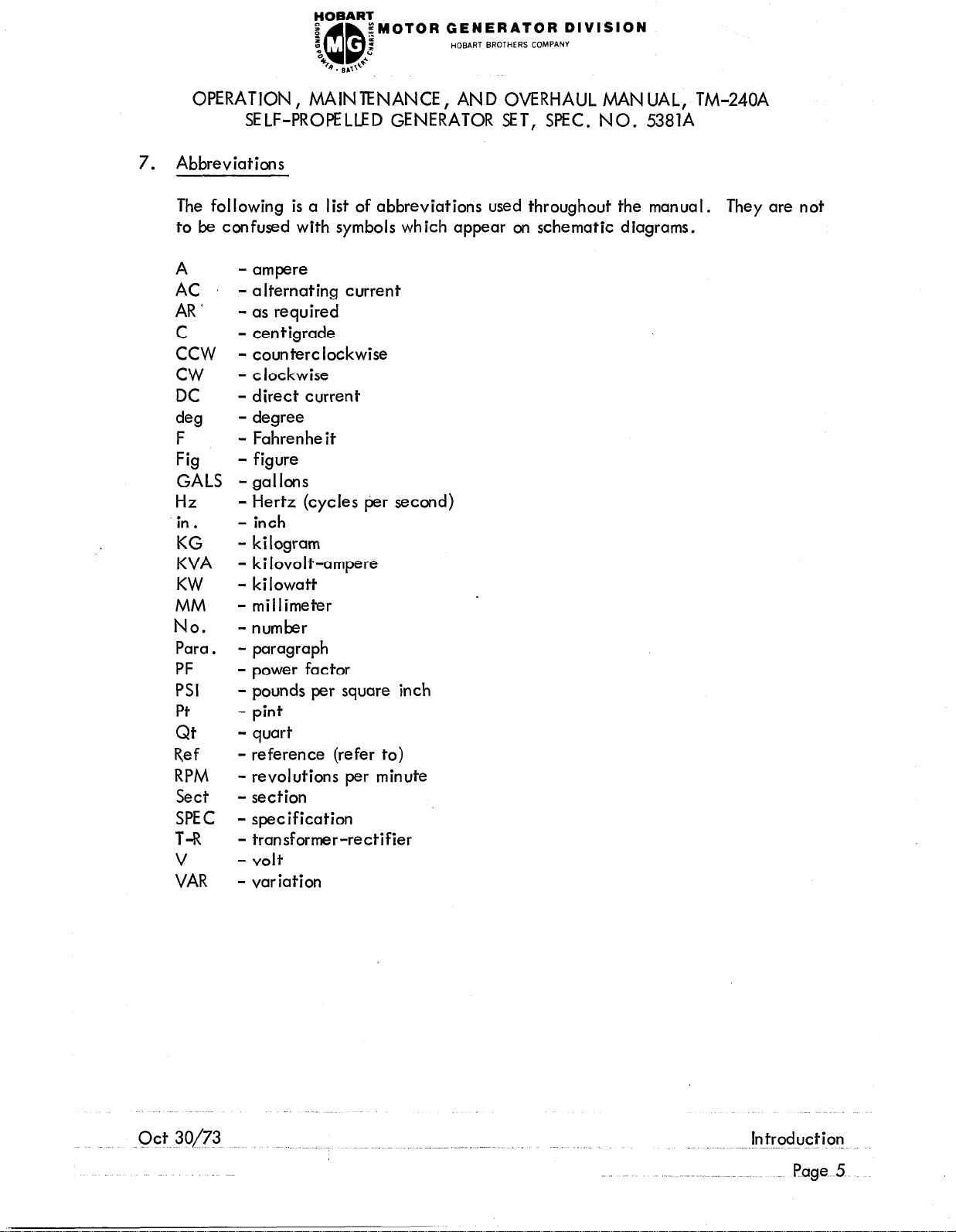
7. Abbreviations
The following is a list of abbreviations used throughout the manual. They are not
to be confused with symbols which appear on schematic diagrams.
A - ampere
AC
- alternating current
AR ’ - as required
C
ccw
cw
DC
de!3
F
Fig
GALS
Hz
in .
KG
KVA
KW
MM
No.
Para.
PF
PSI
Pt
Qt
Ref
RPM
Sect
SPEC
- ten tigrade
- counterclockwise
- clockwise
- direct current
- degree
- Fahrenheit
- figure
- gal Ions
- Hertz (cycles per second)
- inch
- kilogram
- kilovolt-ampere
- kilowatt
- millimeter
-number
- paragraph
- power factor
- pounds per square inch
- pint
- quart
- reference (refer to)
- revolutions per minute
- section
- specification
T-R - transformer-rectifier
V - volt
VAR
- variation
FOBART
.z
a
“0
B . ~ .,,J.
gMOTOR GENERATOR DIVISION
5
2
QQ
HOBART BROTHERS COMPANY
OPERATION, MAINTENANCE, AND OVERHAUL MANUAL, TM-240A
SELF-PROPELLED GENERATOR SET, SPEC. NO. 5381A
lntroc+ction Ott 30/73
Page -6.
nOBAR?
I
:,
“c
QQ
b. s,,++*
OPERATION, MAINTENANCE, AND OVERHAUL MANUAL, TM-240A
SELF-PROPELLED GENERATOR SET, SPEC. NO. 5381A
pMDTDR GENERATOR DIVISION
i
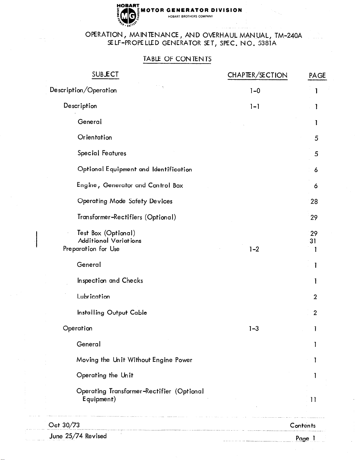
TABLE OF CONTENTS
HOBART BROTHERS COMPANY
SUBJECT
Description/Operation
Description
Genera I
Orientation
Spec ia I Features
Optional Equipment and Identification
Engine, Generator and Control Box
Operating Mode Safety Devices
Transformer-Rectifiers (Optional)
Test Box (Optional)
Additional Variations
Preparation for Use
CHAPTER/SECTION
1-o 1
l-l
l-2
PAGE
1
6
6
28
29
32;
1
General
Inspection and Checks
Lubrication
Installing Output Cable
Operation l-3
Genera I 1
Moving the Cklit Without Engine Power
Operating the Unit
Operating Transformer-Rectifier (Optional
Equipment) 11
1
1
2
2
1
June 25/74 Revised
P!zP 1
.
OPERATION, MAINTENANCE, AND OVERHAUL MANUAL, TM-240A
SELF-PROPELLED GENERATOR SET, SPEC. NO. 5381A
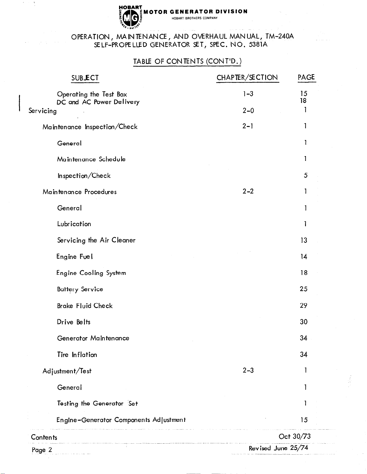
TABLE OF CONTENTS (CONT’D.)
SUBJECT
Operating the Test Box
DC and AC Power Delivery
Servicing
Maintenance Inspection/Check
Genera I
Maintenance Schedule
Inspection/Check
Maintenance Procedures
General
Lubrication 1
Servicing the Air Cleaner
CHAPTER/SECTION
1-3
2-o
2-l
2-2 1
PAGE
:8”
1
1
1
1
5
1
13
Engine Fue I
Engine Cooling System 18
Battery Service 25
Brake Fluid Check
Drive Belts 30
Generator Maintenance 34
Tire Inflation 34
Adjustment/Test
2-3
Genera I
Testing the Generator Set 1
Engine-Generator Components Ad justmen t
14
29
1
1
15
Contents
Page 2
act 30/73
Revised June 25/74
~OFJAI?~
e
a
“c
B
;MOTOR GENERATOR DIVISION
HOBART BROTHERS COMPANY
QD
. 8.0‘
2
c
OPERATION, MAINTENANCE, AND OVERHAUL MANUAL, TM-240A
SELF-PROPELLED GENERATOR SET, SPEC. NO, 538
1A
TABLE OF CONTENTS (CONT’D .)
SUBICT
Chassis Components Adiustment
Trouble Shooting
Theory of Operation
General
Twelve-Volt Electrical System
400-Hz Generator System
Trouble Shooting Procedures
Genera I
Trouble Shooting Chart
Equipment for Trouble Shooting
CHAPTER/SECTION PAGE
2-3 30
3-o 1
3-l 1
1
1
9
3-2
1
1
1
1
Safety
Parts Replacement
Test Values
Trouble Shooting Practices
Electric-Hydraulic Governor Trouble Shooting
Engine Trouble Shooting
II lustrations
Removal/Installation
Engine-Generator Assembly Removal and
Installation
Genera I
4-o
4-l
2
2
2
3
4
5
5
1
1
1
Con tents.
HOBART
e
a
‘c
46
;MOTOR GENERATOR DIVISION
QD
Q. B,T+
p:
z
i
HOBART BROTHERS COMPANY
OPERATION, MAINTENANCE, AND OVERHAUL MANUAL, TM-240A
SELF-PROPELLED GENERATOR SET, SPEC. NO. 538114
TABLE OF CONTENTS (CONT’D.)
SUBJECT
Installation
Individual Components Removal and Installation
General
Generator Control Box Trays
Power Module Panel Assembly
Control Box
Repair
Electrical Repairs
Genera I
Generator Control Box
CHAPTER/SECTION
4-l
5-o
5-l
PAGE
10
1
1
2
4
1
1
1
1
Generator
Engine
Connection Diagrams
Mechanical Repairs
Engine
Generator
Canopy Assembly
Overhaul
Electrical
Genera I
Generator Control Box Assembly
1
1
5-2
1
1
1
1
6-O
1
6-l 1
1
1
Contents
kg9 .~P
act 30/73
GENERATOR DIVISION
HOBART BROTHERS COMPAW
OPERATION, MAINTENANCE, AND OVERHAUL MANUAL, TM-240A
SELF-PROPELLED GENERATOR SET, SPEC. NO. 5381A
TABLE OF CONlENTS (CONT’D.)
SUBJECT
Generator
Mechanical
General
Engine
Generator
I I lustrated Parts List
Introduction
Genera I
Purpose
Arrangement
CHAPTER/SECTION
6-l
6-2
7-o
7-l
PAGE
2
1
1
1
1
1
1
1
1
1
Explanation of Parts List
Manufacturer’s Codes
, Explanation of Manufacturer’s (Vendor)
Code List
Parts List
Explanation of Parts List Arrangement
Symbols and Abbreviations
N umer ica I Index
Explanation of Numerical Index
Manufacturer’s Information
7-2
1
1
7-3 1
1
1
7-4
1
1
8-O 1
1
FOBART
z
a
“c
B . B ,,&
g”OTOR GENERATOR DIVISION
QB
5
5
HOB/\RT BROTHERS COMPANY
OPERATION, MAINTENANCE, AND OVERHAUL MANUAL, TM-240A
SELF-PROPELLED GENERATOR SET, SPEC-. NO. 5381A
LIST OF ILLUSTRATION S
CHAPTER/
SECTION NUMBER
l-l
l-l
l-l 3
l-l
l-l 5
l-l
l-l
l-l 8
l-l 9
l-l 10
l-l 11
FIGUTE
1
2
4
6
7
TITLE
Self-Propelled Generator Set
Specifications and Capabilities (Sheets 1 and 2)
Component Identification (Sheets 1 and 2)
Air Cleaner and Service Indicator
Control Box
Generator Control Tray
Protective Relay Tray
Voltage Regulator Tray
Voltage Regulator
Power Module
Test Box Assembly (Optional)
l-2 1 Engine Oil Gage Rod and Filler Cap
l-2
l-2 3
l-2
l-2 5
l-3 1
2
4
Output Terminals (Typical)
Opening for Output Cable (Typical)
T-R Output Cable lnsta I lation
T-R Cable Plug Boxes
Engine and Generator Controls and Instruments
(Sheets 1 and 2)
l-3
l-3
l-3
l-3
l-3
l-3
l-3
l-3
Starting Aid
Driver’s Compartment Controls (Typical)
Transformer-Rectifiers (Typical Installation)
28.5-V DC T-R Control Panel
28.5-V DC T-R Output Voltage Adiustment 14
112-V DC T-R Control Panel 16
Test Box Operating Controls
Test Receptacle Connector (Typical) 18
PAGE
NO.
1
3-4
8-9
12
16
18
21
24
25
26
30
2-3
5
8
12
14
17
2-l
2-l
2-l
2-l
2-2
2-2
2-2
2-2
2-2
2-2
Contents
Page 6
1
2
3
4
1
2
3
Maintenance Schedule
Vibration Damper Hub
Lamp Identification Chart 18
Fuse Chart 19
Lubrication Chart
Lubricants and Fluids Chart
Symbols and Time Intervals
4 Oil and Coolant Capacities
5
6
Temperature and Viscosity Chart
Oil Filter
2 thru 4
14
yOBAR7
e
f
‘0
4?
;MOTOR GENERATOR DIVISION
HOBPlRT BROTHERS COMPANY
@
4. B.0
:
‘Q+
OPERATION, MAINTENANCE, AND OVERHAUL MANUAL, TM-240A
SELF-PROPELLED GENERATOR SET, SPEC. NO. 5381A
LIST OF ILLUSTRATIONS (CONT’D.)
CHAPTER/
FIGURE
SECTION NUMBER
2-2
2-2
2-2 ’
2-2
2-2
2-2
2-2
2-2
2-2
2-2
2-2
2-2
2-2
2-2
2-2
7
8
9
10
11
12
13
14
15
16
17
18
19
20
21
2-3 1
2-3
2
2-3 3
2-3 4
2-3 5
2-3
2-3
6
7
2-3 8
2-3 9
2-3
2-3
2-3
10
11
12
2-3 13
2-3 14
2-3 15
2-3
16
2-3 17
213
18
2-3 19
TITLE
Water Pump Lubrication
Fan Hub Lubrication
Rear Axle, Transmission, and Steering Gear Grease
Filler Plugs
Air Cleaner Cartridge Replacement
Fuel Filter
Fuel Pump Screen and Priming Plug
Coolant Drains
C
orrosion Resistor
Battery Access Doors
Battery Installation
Master Brake Cylinder
Belt Deflection, Tension Check Chart
Belt Deflection Check
Alternator Belt Adjustment
Fan Belt Adjustment
Generator Control Box Interior
Engine and Generator Controls and Instruments
(Sheets 1 and 2)
Terminal Boards
Generator and Exciter Stator Test
Excitation Resistors
Voltage Regulator Adjustments
Voltage Regulator Damping Adjustments
Engine Specifications
Governor Linkage Adjustment
Magnetic Pickup Adjustment
Hydraulic Actuator Adjustment
Governor Electric Control Box and Potentiometer
Acce lerator Linkage Adiustmen t
Clutch Pedal Adiustment
Brake Peda I Ad justmen t
Parking Brake Adjustment
Brake Shoe Adjustment
Brake Bleeder Valve (Rear Wheel)
Gearshift Micro Switch Adjustment
PAGE
NO.
9
10
12
14
16
17
22
24
26
28
29
30
31
33
33
2
4-5
6
14
16
17
19
20
23
24
26
28
30
31
33
34
36
38
40
3-l 1
3-l
w W??
2
Engine Circuit Schematic Diagram
Generator Circuit Schematic Diagram
2
4
Contents
Page 7

FOBART
e
a
‘0
b . B ,,+**
;MOTOR GENERATOR DIVISION
2
QD
HOBART BROTHERS COMPANY
OPERATION, MAINTENANCE, AND OVERHAUL MANUAL, TM-240A
SELF-PROPELLED GENERATOR SET, SPEC. NO. 5381A
LIST OF ILLUSTRATION S (CON T’D. )
CHAPTER/
FIGURE
SECTION NUMBER
3-l 3
3-l
3-l
3-2
3-2
4
t5
1
2
3-2 3
3-2
3-2
3-2
4
5
6
4-l 1
4-l
4-l
2
3
4-l 4
4-l 5
4-l
6
4-l 7
PAGE
TITLE
Governor Speed Setting Potentiometer Schematic
Governor Actuator Cross-Section
Electric Governor Voltage Values
NO.
7
8
9
Engine and Generator Controls and Instruments
(Sheets 1 and 2)
6-7
Starter and Solenoid Switch 8
Termina I Boards 9
Exe itation Resistors 10
End View of Voltage Regulator Amphenol Connector
10
Trouble Shooting Chart 11 thru 30
Self-Propelled Generator Set 3
Accelerator Control Cable Connection 4
Steering Gear 5
Clutch Shaft and Linkage
7
Peda Is and Master Cylinder 8
Pedals Assembly Attachment
Engine-Generator Hoisting Arrangement (Typical)
8
9
4-2
4-2
5-l
5-l
5-l
5-l
5-l
5-l
5-2
6-l
6-l
6-l
6-l
6-l
6-l
6-l
6-l
1
2
1
2
3
Control Tray Removal (Typical)
Power Module Panel Assembly 3
Generator Circuit Connection Diagram 2
Engine Circuit Connection Diagram
Control Box Connection Diagram 4
4 Generator Control Tray Connection Diagram
5
6
Protective Monitor Tray Connection Diagram
Power Module Connection Diagram
No Illustrations
1
2
3
4
5
6
7
8
Generator Lifting Arrangement (Typica I) 2
Generator-to-Engine Connection
Generator Fan and Coupling (Typical)
Wrench Positioned to Prevent Engine Rotation (Typical) 5
Flexible Coupling (Removal or Installation) (Typical)
Coupling Hub and Bushing
Generator Exploded View
Exciter Rotor (Removal or Installation)
2
3
5
6
7
3
4
6
6
8
9
Contents
Page 8
._
Ott 38/73
.-~. .__
GENERATOR DIVISION
HOBART BROTHERS COMPANY
OPERATION, MAINTENANCE, AND OVERHAUL MANUAL, TM-240A
SELF-PROPELLED GENERATOR SET, SPEC. NO. 538114
LIST OF ILLUSTRATION S (CON T’D , )
CHAPTER/ FIGURE
SECTION NUMBER
TITLE
6-l 9 Positioning Generator Rotor (Removal or Installation)
(Typical)
6-l 10
6-1
6-l
11
12
6-l 13
6-l
6-1
6-l
14
15
16
Preparation for Rotor lnstal lation (Typica I)
Cleaning and Lubricating Hub and Bearing (Typical)
Routing Exciter Leads (Typical)
Installing Exciter Housing (Typical)
Exciter Rotor Installation (Typical)
Pulling Generator Rotor Field Leads (Typical)
Fan Housing-to-Flywheel Adapter Measurement
(Typical)
6-l 17
6-l
18
Torquing Hub Screws (67 ft-lbs)
Measuring Flexible Coupling Location on Generator
Shaft (Typical)
6-l
19
Positioning Generator to Engine (Typical)
6-l 20 Torquing Coupling-to-Flywheel Screws (150 ft-lbs)
6-2
7-3
7-3
7-3
7-3
7-3
7-3
7-3
7-3
7-3
7-3
7-3
7-3
7-3
7-3
7-3
7-3
7-3
7-3
7-3
7-3
7-3
7-3
1
2
3
4
5
6
7
8
9
10
11
12
12A
-13.
14
15
16
17
18
19
‘20
21
No Illustrations
Self-Propelled Generator Set
Canopy Assembly
Generator Set Without Canopy
Control Box Assembly
Generator Control Tray Assembly
Protective Relay Tray Assembly
Voltage Regulator Tray Assembly
Power Module Panel Assembly
Control Box Front Panel Instruments and Controls
Control Box and Internal Components Group
Radiator and Cooling System Group
Floorplate, Pedals, and Brake Group
Floorplate, Pedals and Brake Group
Hydraulic Brake Master Cylinder
Steering Group
Steering Gear
Engine and Drive Train Group
Governor and Accelerator Linkage Group
Governor Oil Lines
Fuet-and Oil Lines Group
Stator Terminal Panel Assembly ‘.-
Gear-shift Safety Box and Back-up Light Switch Group
PAGE
NO.
10
14
15
16
16
17
18
19
21
21
22
23
2
4
6
8
10
14
18
20
24
26
28
32
35A
36
38
40
42
46
48
50
52
54
Oct30/73
June 25/74Revised
Contents
page 9
FOBAR’I:
e
a
t
B. *,,+*’
;MOTOR GENERATOR DIVISION
QD
:
z
HOBART BROTHERS COMPAN”
OPERATION, MAINTENANCE, AND OVERHAUL MANUAL, TM-240A
SELF-PROPELLED GENERATOR SET, SPEC. NO, 5381A
LIST OF ILLUSTRATIONS (CON T’D. 1
CHAPTER/
SECTlObi
7-3
7-3
7-3
7-3
7-3
7-3 27
7-3 28
7-3
7-3
7-3
FIGURE
NUMBER
22
,23
TITLE
Transmission Assembly
Clutch Group
PAGE
NO,
56
66
/ 24 Generator Group 68
25 Seat and Transformer-Rectifier Group
26 Output Terminal Panel Assembly
70
74
Transformer-Rectifier Terminal Pane I Assembly 76
29
30
31
Vehicular Lights Group
Body and Frame Group 80
Battery Group
Axle Group 86
78
84
FOBART
8
5
“c
%
;MOTOR GENERATOR DIVISION
QD
*. B,,I~~
oz
2
HOBART BROTHERS COMPANY
OPERATION, MAINTENANCE, AND OVERHAUL MANUAL, TM-240A
SELF-PROPELLED GENERATOR SET, SPEC. NO, 5381A
CHAPTER 1. DESCRIPTION/OPERATION
TABLE OF CONTENTS
SUBJECT
Description
General
Orientation
Specia I Features
Protective Monitor
Pull-out Trays
Voltage Regulator
Test Circuitry
Electric Hydraulic Governor
Optional Equipment and Identification
CHAPTER/SECTION PAGE
l-l
1
1
5
5
5
5
5
5
5
6
Variation No. 1
Variation No. 2
Combinations of Variations
Future Variations
Engine, Generator and Control Box
Basic Engine
Engine Manufacturer’s Equipment
Electrical system
filter
I
Fue
Oil filter
6
6
6
6
6
6
7
7
7
GENERATOR DIVISION
HOBART BROTHERS COMPANY
OPERATION, MAINTENANCE ,. AND OVERHAUL MANUAL, TM-240A
SELF-PROPELLED GENERATOR SET, SPEC. NO. 5381A
TABLE OF CONTENTS (CONTINUED)
SUBJECT
Automatic shut-down system
Fue I shut-off valve
Oil pressure switch
Engine overspeed protection
Engine-cooling fan
Hobart Installed Engine Equipment
Electric-hydraulic governor
Electric control unit
Hydraulic actuator
Magnetic pickup
CHAPTER/SECTION
l-l
PAGE
7
7
7
10
10
10
10
10
11
11
Engine safety device
Coolant temperature switch
Air cleaner
Mufflers
Radiator
Generator
Control Box Assembly
Engine instruments
Ammeter
Temperature gage
Oi I pressure gage
11
11
11
12
12
12
13
13
13
13
14
l-O_
Page 2
- ..~.~_. _
octt30/73
 Loading...