

Page 1
Chain Saw
Model CS 51EA
Handling instructions
Note:
Before using this machine, carefully read through these HANDLING INSTRUCTIONS
to ensure effi cient, safe operation. It is recommended that these INSTRUCTIONS be
kept readily available as an important reference when using this machine.
Page 2

English
MEANINGS OF SYMBOLS
NOTE: Some units do not carry them.
Symbols
WARNING
The following show symbols used for the machine. Be sure that you understand their meaning before use.
It is important that you read, fully understand and
observe the following safety precautions and
warnings. Careless or improper use of the unit may
cause serious or fatal injury.
Read, understand and follow all warni ngs and
instructions in this manual and on the unit.
Emergency stop
Fuel and oil mixture
Always wear eye, head and ear protectors when using
this unit.
Warni ng, kickback danger. Be careful of possible
sudden and accidental upward and/or backward
motion of the guide bar.
One-handed usage not permitted. While cutting, hold
saw fi rmly with both hands with thumb fi rmly locked
around front handle.
Chain brake Carburetor adjustment - High speed mixture
Choke Oil pump adjustment
On/Start Priming pump
Off /Stop Decompression valve
Contents
WHAT IS WHAT? .............................................................................. 3
WARNINGS AND SAFETY INSTRUCTIONS .................................. 3
SPECIFICATIONS ............................................................................ 5
ASSEMBLY PROCEDURES ............................................................. 5
OPERATING PROCEDURES ........................................................... 6
MAINTENANCE .............................................................................. 10
Parts breakdown
Chain oil fi ll
Carburetor adjustment - Idle speed
Carburetor adjustment - Low speed mixture
2
Page 3
English
15
17
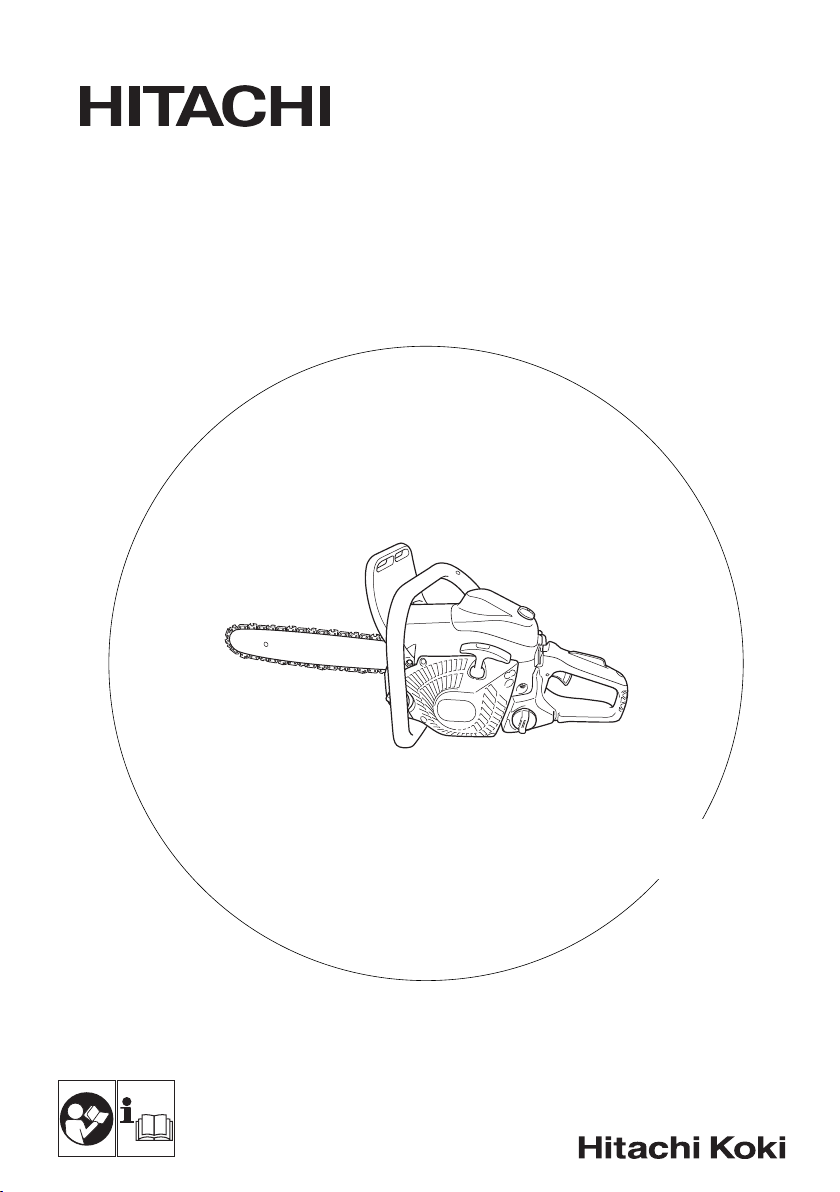
WHAT IS WHAT?
1. Throttle lever: Device activated by the operatorʼs fi nger, for
controlling the engine speed.
2. Throttle lever lockout: Device that prevents the accident al
operation of the throttle lever until manually released.
3. Stop switch: Device for allowing the engine to be started or
stopped.
4. Oil tank cap: For closing
5. Recoil starter: Pull handle to start the engine.
6. Front handle: Suppor t handle located at or towar ds the front of
the engine housing.
7. Fuel tank cap: For closing the fuel tank.
8. Choke lever: Device for enriching the fuel/air mixture in the
carburetor, to aid
9. Priming pump; Device for supplying extra fuel, to aid starting.
10. Decompression va lve: Device for reducing the compression
pressure to aid starting.
11. Guide bar: The part that supports and guides the saw chain.
12. Saw chain: Chain, serving as a cutting tool.
13. Cha in brake (Fro nt hand guard):
the chain.
14. Spiked bumper: Device for acting as a pivot when in contact with
a tree or log.
15. Cha in catcher: Device for restraining the saw chain.
16. Guide bar cover: Device for covering the guide bar and saw
chain when the unit is not
17. Combi box spanner: The tool for removing or installing a spark
plug and tensioning the saw chain.
18. Handling instructions: Included with unit. Read before operation
and keep for future reference to learn proper, safe techniques.
the oil tank.
starting.
Device for stopping or locking
being used.
16
17
16
10
13
2
8
9
15
14
12
11
6
5
1
4
37
18
WARNINGS AND SAFETY INSTRUCTIONS
Operator safety
○ Always wear a safety face shield or goggles.
○ Gloves should be used when sharpening chain.
○ Always wear safety protective equipment such as jacket,
trousers, gloves, helmet, boots with steel toe-caps and non-slip
soles, and eye, ear and leg protection equipment whenever you
use a chain saw. For
suitable for climbing techniques. Do not wear loose clothing,
jewelry, short pants, sandals or go barefoot.
Secure hair so it is above shoulder length.
○ Do not operate this too l when you are tired, ill or under the
infl uence of alcohol, drugs
○ Never let a child or inexperienced per son operate the machine.
○ Wear hearing protection. Pay attention to your surroundings.
Be aware of any bystanders who may be signaling a problem.
Remove safet y equipment immediately upon shutting off engine.
○ Wear head protection.
○ Never start or run the engine
Breathing exhaust fumes can kill.
○ For respirator y protection, wea r a protection mask while emitting
the chain oil mist and dust from sawdust.
○ Keep handles free of oil and fuel.
○ Keep hands away from cutting equipment.
○ Do not grab or hold the unit by
○ When the unit turned o ff , make sure the cut ting attachment has
stopped before the unit is set down.
working in trees the safet y boots must be
or medication.
inside a closed room or building.
the cutting equipment.
○ When operation is prolonged, take a break from time to time
so that yo u may avoid possible Hand-Arm Vibration Syndrome
(HAVS) which is caused by vibration.
The operator must obey the local regulations of cutting area.
○
WARNING
○ Antivibration systems do not guarantee that yo u will not sustain
Hand-Arm Vibration Syndrome or carpal tunnel syndr ome.
Therefore, continual end regular users should monitor closely
the condition of their hands and fi ngers. If any of the above
symptoms appear, seek medical advice immediately.
○ Long or continuous ex posure to high
permanent hearing impairment. Always wear approved hearing
protection when operating a unit/machine.
○ If you are using any medical electric/electronic devices such
as a pacemaker, consult your physician as well as the device
manufacturer prior to operating any power equipment.
Unit/machine safety
○ Inspect the entire unit/machine before
damaged parts. Check for fuel leaks and make sure all fasteners
are in place and securely tightened.
○ Replace parts that are cracked, chipped or damaged in any way
before using the unit/machine.
○ Make sure the side case is properly attached.
○ Keep others away when making carburetor
○ Use only accessories as recommended for this unit/machine by
the manufacturer.
○ Never let the chain strike any obstacle. If the chain makes
contact, the machine should be stopped and checked carefully.
noise levels may cause
each use. Replace
adjustments.
3
Page 4

English
○ Make sure the automatic oiler is working. Keep the oil tank fi lled
with clean oil. Never let chain run dry on the bar.
○ All chain saw service, other than the items listed in the
operatorʼs/ ownerʼs manual, should be performed by competent
chain-saw service personnel. (For example,
used to remove the fl y wheel or if an improper tool is used to hold
the fl ywheel in order to remove the clutch, structural damage
to the fl ywheel could occur and could subsequently cause the
fl ywheel to burst.)
WARNING
○ Never modify the unit/machine in any way. Do not use your unit/
machine for any job except that for which it is intended.
○ Never use chain saw without any safety equipment or that has
faulty safety equipment. It could result in serious personal injury.
○ Using guide bar/chain other than
manufacturer which are not approved, could result in a high risk
of personal accidents or injury.
Fuel safety
○ Mix and pour fuel outdoors and where there are no sparks or
fl ames.
○ Use a container approved for fuel.
○ Do not smoke or allow smoking near fuel or
while using the unit/machine.
○ Wipe up all fuel spills before starting engine.
○ Move at least 3 m away from fueling site before starting engine.
○ Stop engine and let it cool for a few minutes before removing fuel
tank cap.
○ Empty the fuel tank before storing
recommended that the fuel be emptied after each use. If fuel is
left in the tank, store so fuel will not leak.
○ Store unit/machine and fuel in area where fuel vapors cannot
reach sparks or open fl ames from water heaters, electric motors
or switches, furnaces, etc.
WARNING
Fuel is easy to ignite or get explo sion or inhale fumes, so that pay
special attention when handling or fi lling fuel.
Cutting safety
○ Do not cut any material oth er than wo od or wooden objects.
○ For respiratory protection, wear an aerosol protection mask
when cutting the wood after insecticide has
○ Keep others in cluding children, animals, by standers and helpers
outside the hazard zone. Stop the engine immediately if yo u are
approached.
○ Hold the unit/machine fi rmly with the right hand on the rear
handle and the left hand on the front handle.
○ Keep fi rm footing and balance. Do not
○ Keep all parts of your body away from the muffl er and cutting
attachment when the engine is running.
○ Keep Bar/Chain below waist level.
○ Before felling a tree, the operator must be accustomed to the
sawing techniques of the chain saw.
○ Be sure to pre-plan a safe
○ While cutting, hold the unit/machine fi rmly with both hands with
thumb fi rmly locked around front handle, and stand with feet well
balanced and your body balanced.
○ Stand to the side of the saw when cutting - never directly behind
it.
○ Always keep the spiked
chain may suddenly be drawn into a tree, if so equipped.
○ When completing a cut, be ready to hold up the units as it breaks
into clear, so it will not fol low through and cut yo ur legs, feet or
body, or contact an
○ Be alert again st kickback (when saw kicks up and back at
operator). Never cut with the nose of the bar.
○ When relocating to a new work area, be sure to shut off the
machine and ensure that all cut ting at tachments are stopped.
○ Never place the machine on the
○ Always ensure that the engine is shut off and any cutting
attachments have completely stopped before clearing debris or
removing grass from the cutting attachment.
○ Always carry a fi rst-aid kit when operating any power equipment.
exit from a failing tree.
bumper face to a tree, because the
obstruction.
ground when running.
if improper tool s are
recommended by the
the unit/machine or
the unit/machine. It is
been applied.
over-reach.
4
○ Never star t or run the engine inside a closed room
and/or near the infl ammable liquid. Breathing exhaust fumes
can kill.
Maintenance safety
○ Maintain the unit/machine according to recommended
procedures.
○ Disconnect the spark plug before performing maintenance
except for carburetor adjustments.
○ Keep others away when making carburetor adjustments.
○ Use only genuine HITACHI replacement parts as recommended
the manufacturer.
by
CAUTION
Do not disassemble the recoil starter. You may get a possibilit y
of personal injury with recoil spring.
WARNING
Improper maintenance could result in serious engine damage or
in serious personal injury.
Tra ns po rt and storage
○ Carry the unit/machine by hand with the engine stopped and the
muffl er away from your body.
○ Allow the engine to cool, empty the fuel tank, and secure the
unit/machine before storing or
○ Empty the fuel tank before storing the unit/machine. It is
recommended that the fuel be emptied after each use. If fuel is
left in the tank, store so fuel will not leak.
○ Store unit /machine out of the reach of children.
○ Clean and maintain the unit
○ Make sure stop switch is off when transporting or storing.
○ When transporting or storage, cover chain with guide bar cover.
If situations occur which are not covered in this manual, take care and
use common sense. Contact HITACHI dealer if you
Pay special attention to statements preceded by the following words:
WARNING
Indicates a strong possibility of severe personal injury or loss of
life, if instructions are not followed.
CAUTION
Indicates a possibility of personal injury or equipment damage, if
instructions are not followed.
NOTE
Helpful information for correct function and use.
WARNING
KICKBACK DANGER (Fig. 1)
One of the most severe dangers when work ing with a chain saw is
the possibility of kickback. Kickback may occur when the upper tip
of the guide bar touches an object, or when the woo d closes in and
pinches the saw chain in the cut. Tip contact
cause a lightning fast reverse reaction, kicking the guide bar up and
back toward yo u. Pinching the saw chain along the top of the guide
bar may also push the guide bar rapidly back towar ds you. Either of
these reactions may cause you to lose control
result in serious personal injury. Even though your saw has safety
built into its design, you should not rely on these safety featu res
exclusive ly. Know where your bar tip is at all times. Kickback does
occur if you allow the kickback zone (1) of the bar
Do not use that area. Kickback from pinching is caused by a cut
closing and pinching the upper side of the guide bar. Study your cut
and make sure it will open as you cut through. Maintain control when
the engine is running by always keeping
your right hand on the rear handle, your left hand on the front handle
and your thumbs and fi ngers encircling the handles. Always hold the
saw with both hands during operation and cut at high engine speed.
Follow manufacturer's sharpening and maintenance instructions
the saw chain. The lack of this maintenance may increase the
for
possibility of kickback.
transporting in a vehicle.
carefully and store it in a dry place.
of the saw which could
a fi rm grip on the saw with
Fig. 1
or building
need assistance.
in some cases may
to touch an object.
1
Page 5
English
SPECIFICATIONS
○ Code “CS” of model name means “Chain saw”
Typ e of equipment Chain saw, portable
Engine Size (cm
Spark Plug NGK BPMR-7A
Fuel Ta nk Capacity (cm
Chain Oil Tan k Capacity (cm
Dry Weight (kg)
(Without guide bar and chain)
3
) 50.1
3
)530
3
)270
Chain pitch (mm) 8.26
Chain gauge (mm) 1.2 7
Sound pressure level LpA (d B (A)) by ISO 22868
Equivalent
Uncertainty
Sound power level Lw A (dB (A)) by ISO 22868
Measured
Sound power level Lw A (dB (A)) by 2000/14/EC
Measured
Guaranteed
Vibration level (m/s
Front handle
Rear handle
Uncertainty
2
) by ISO 22867
Guide bar length (mm) 400 450 500
Typ e of chain
Max. engine power
by ISO 7293 (kW)
Max. engine speed (min
Idle engine speed (min
Specifi c fuel consumption at maximum engine
power (g/kWh)
-1
)13500
-1
) 3000
Max. chain speed (m/sec) 26.0
Sprocket (numbe r of teeth) 7
NOTE: Eq uivalent noise level/vibration levels are calculated as the time-weighted energy tot al for noise/vibration levels under various
working conditions with the following time distribution: 1/3 idle, 1/3 full, 1/3 racing speed.
*Al l data subject to change without notice.
Model CS51EA (40S) CS51E A (45S) CS51E A (50S)
5.1
104
1
Uncertainty
3.3
2.7
0.8
95VPX
(Oreg on)
113
114
117
3.3
2.7
0.8
2
2.5
439
3.3
2.7
0.8
20BPX
(Oreg on)
ASSEMBLY PROCEDURES
WARNING
Never try to start engine without side case, bar and chain
securely fastened.
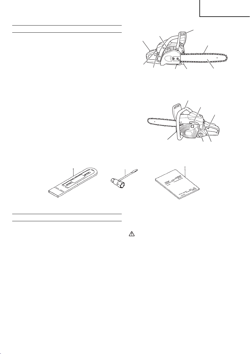
1. Pull the front hand guard (2) toward the front handle to check that
the chain brake is disengaged. (Fig. 2)
2
Fig. 2
2. Remove guide bar clamp nuts (3). Remove the side case (4) .
(Fig. 3)
4
3
Fig. 3
5
Page 6
English
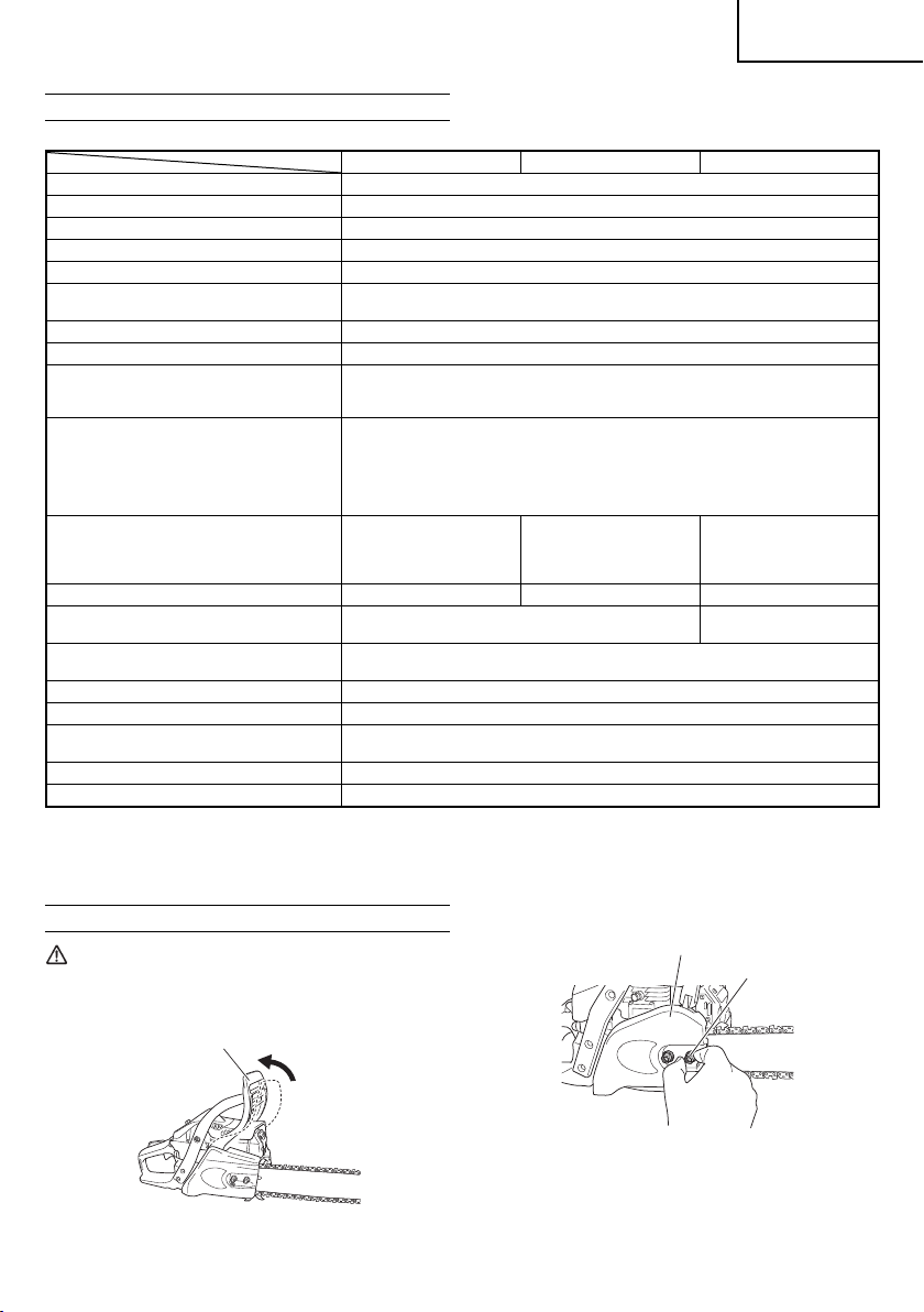
the guide bar (5 ) onto the bolts (6), then push it toward the
3. Install
sprocket (7) as far as it will go.
10
11
4
4. Confi rm the direction of saw chain (12) is correct as in the fi gure,
and align the chain on the sprocket. (Fig. 5)
5. Guide the chain drive links into the bar groove all around the bar.
6. Install the side case (4) onto the bolts (6).
Make sure that the boss of chain tension adjust bolt (8) fi ts into
the hole (9) of the bar. (Fig. 4)
The brake lever
the side of the front hand guard.
Then tighten the guide bar clamp nuts (3) by hand that allows the
guide bar end to move up and down easily.
7. Raise the bar end, and tighten the chain (12) by turning the
tension adjustment bolt (13) clockwise. To check proper ten sion,
lightly lift up the center of chain and there should be about 0.5
– 1.0 mm clearance (14) between bar and edge of drive link.
(Fig. 6, 7)
0.5 – 1 mm
6
Fig. 4
12
Fig. 5
(11) of the side case must fi t the groove (10) on
13
14
Fig. 6
Fig. 7
6
7
8
5
9
(
Fig. 3
)
12
CAUTION
PROPER TENSION IS EXTREMELY IMP ORTANT
8. Raise the bar end and securely tighten the guide bar clamp nuts
with the combi box spanner. (Fig. 7)
9. A new chain will stretch so adjust the chain after a few cuts and
watch chain tension carefully for the fi rst half hour of
NOTE
Check the chain tension frequently for optimum performance
and durability.
CAUTION
○ When the chain is excess ively tightened, the bar and chain will
be damaged rapidly. Conversely, when the chain is excessive ly
loosened, it may get out of the groove in the bar.
○ Always wear gloves when touching the chain.
WARNING
During operation, hold chain saw fi rmly with both hands. A single
hand operation may cause serious injury.
cutting.
OPERATING PROCEDURES
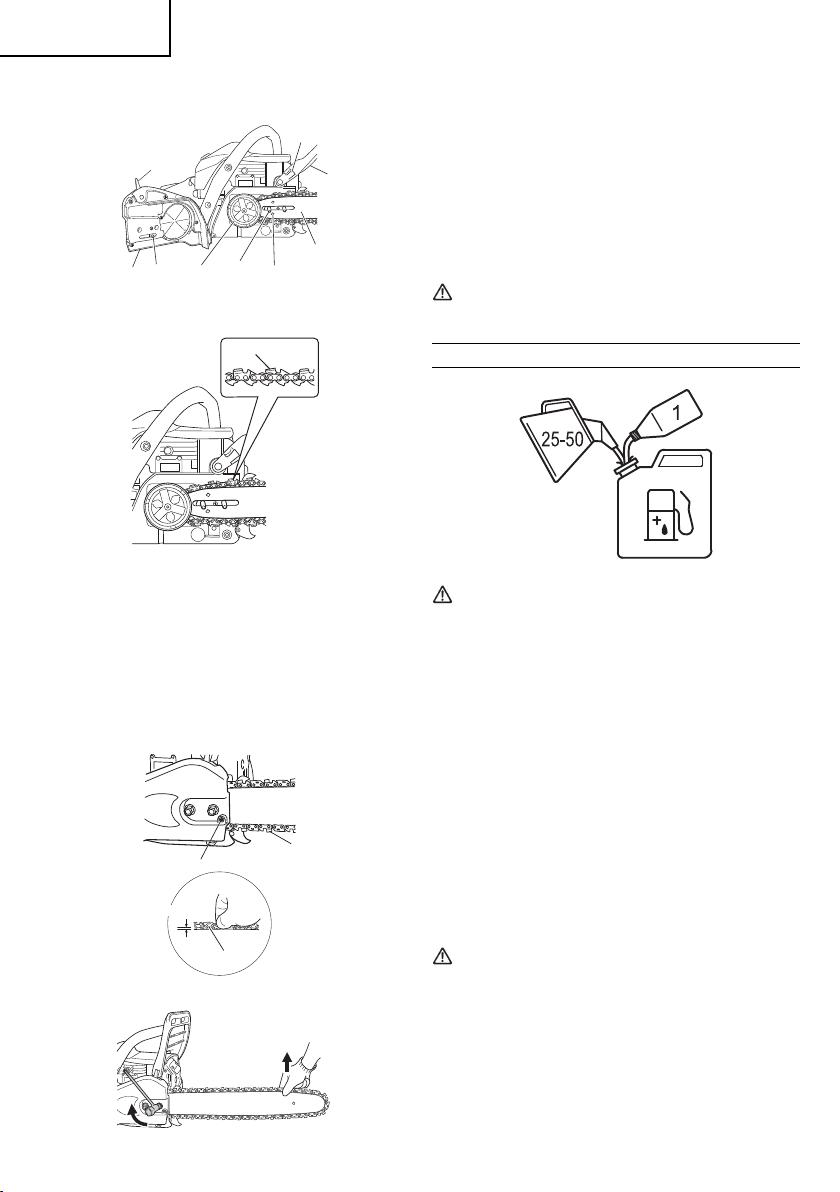
Fuel (Fig. 8)
Fig. 8
WARNING
○ The chain saw is equipped with a two-stroke engine. Always
run the engine on fuel, which is mixed with oil. Provide good
ventilatio n, when fueling or handling fuel.
○ Fuel contains highly fl ammable and it is possible to get the
serious personal injury when inhaling or spilling on you r body.
Always pay attention when handling fuel. Always have good
ventilatio n when handling fuel inside building.
Fuel
○ Always use branded 89 octane unleaded gasoline.
○ Use genuine two-cycle oil or use a mix between 25:1 to 50:1,
please consult the oil bottle for the ratio or HITACHI dealer.
○ If genuine oil
oil express ly labeled for air-cooled 2-cycle engine use (JASO
FC GRADE OIL or ISO EG C GRADE). Do not use BIA or TCW
(2-str oke water-cooling type) mixed oil.
○ Never use multi-grade oil (10 W/30) or waste oil.
○ Always mix fuel and oil in
Always start by fi lling half the amount of gasoline, which is to be
used.
Then add the whole amount of oil. Mix (sh ake) the fuel mixture. Add
the remaining amount of gasoline.
Mix (shak e) the fuel-mix thoroughly before fi lling the fuel tank.
Fuelin g
WARNING (Fig. 9)
○ Always shut off the engine before refueling.
○ Slowly open the fuel tank (15), when fi lling up with fuel, so that
possible overpressure disappears.
○ Tighten the fuel cap carefully, after fueling.
○ Always move the unit at least 3 m from the fueling area before
starting.
○ Always
soap.
○ Be sure to check any fuel leaking after refueling.
Before fueling, clean the tank cap area carefully, to ensure that no
dirt falls into the tank. Make sure that the fuel is well mixed by shaking
the container, before fueling.
is not availabl e, use an anti-oxidant added quality
a separate clean container.
wash any spilled fuel from clothing immediately with
Page 7

English
2
15
16
Fig. 9
Chain oil (Fig. 9)
Fill up with chain oil (16) . Always use good quality chain oil. When the
engine is running, the chain oil is automatically discharged.
NOTE
When pouring fuel (15) or chain oil (16 ) into the tank, place the
unit with cap side up. (Fig. 9)
ADJUSTMENT
The chain oil quantity discharged through the lubrication system
is adjusted to the maximum in the factory. Adjust the quantity in
accordance with the operating condition.
Tur n the adjusting screw (17 ) counterclockwise to increase the
quantity and turn it clockwise to decrease the quantit y. (Fig. 10)
Chain brake operation (Fig. 2, 11)
Chain brake is designed to activate in an emergency such as kickback action.
Application of brake is made by moving the front hand guard towards
the bar. During the chain brake operation, even if the throttle lever
is pulled, the engine speed does
not turn. To release the brake, pull the front hand guard toward the
front handle.
If the engine keeps rotating at high speed with the brake engaged,
the clutch will overheat causing trouble.
When the brake engages during operation, immediately release the
throttle lever to slow
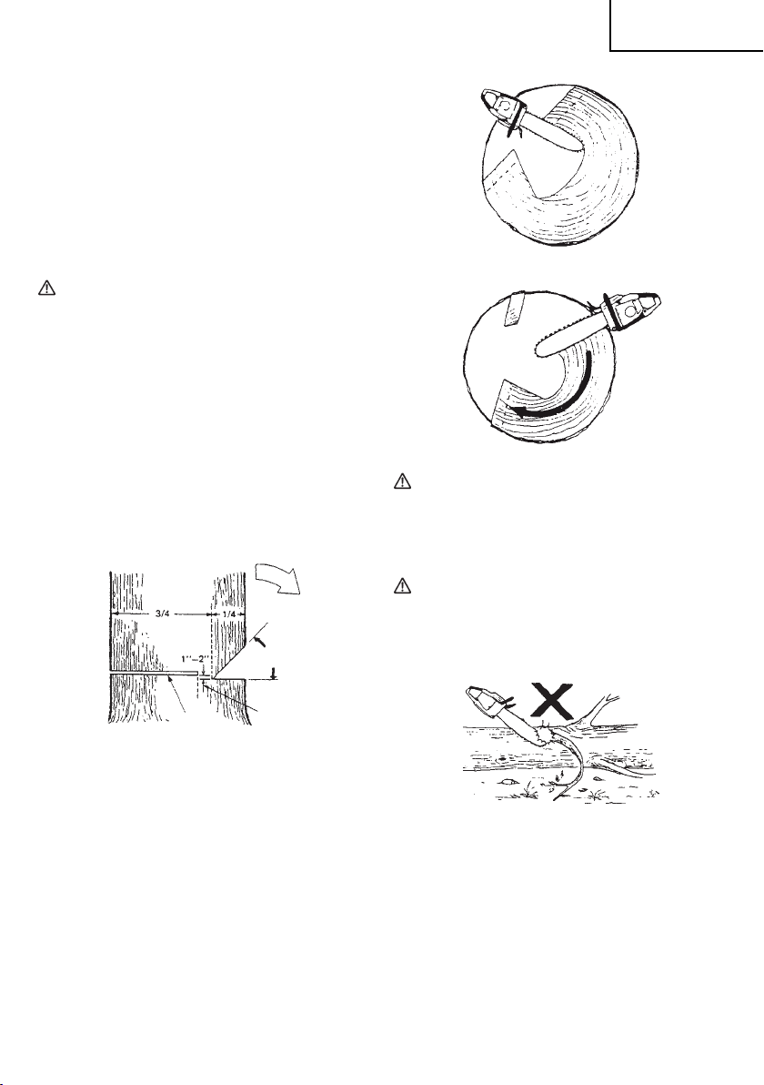
How to confi rm the activation of the chain brake
1) Tur n o ff the engine.
2) Holding the chain saw horizontally, release your hand from the
front handle, hit the tip of the guide bar to a stump or a piece
of wood, and confi rm brake operation.
bar size.
OF CHAIN OIL SUPPLY
17
Fig. 10
not increase and the chain does
down the engine.
Operating level varies by
Fig. 11
1. Set ignition switch (18) to ON position. (Fig. 12)
18
*Push priming pump (2 0) several times so that fuel fl ows through
bulb into carburetor. (Fig. 13)
19
2. Pull the choke lever (19) to choked position (Fig. 13).
This will automatically lock to the half-throttle.
3. Push the decompression val ve (21).
The valve (21) will automatically return to the original position once
the engine has started. (Fig. 14).
Fig. 12
20
Fig. 13
21
In case the brake is not e ff ective, ask our dealer for inspection and
repairs.
Starting (Fig. 11- 16)
CAUTION
Before starting, make sure chain brake is engaged and that the
bar/chain does not touch anything. (Fig. 11)
Fig. 14
7
Page 8

English
4. Pull recoil starter briskly, taking care to ke ep the handle in your
grasp and not allowing it to snap back. (Fig. 15)
5. When you hear fi rst ignition, return the choke lever (19 ) all the
way in. (Fig. 13)
6. Push the decompression valve.
7. Pull re coil starter briskly ag ain in the aforementioned manner.
(Fig. 15)
NOTE
If engine does not start, repeat procedures from 2 to 7.
8. As soon as
throttle lever lockout (22) and release immediately. (Fig. 16)
Then half-throttle is disengaged.
Pull the front hand guard (2) toward the front handle to disengage
the chain brake.
Allow the engine about 2-3 minutes to warm up before subjecting
it
Do not run the engine at high speed without the load to avoid
shortening the life of the engine.
engine star t, pull throttle lever (23) full once with
to any load.
Fig. 15
22
WARNING
Do not stand in-line with chain when cutting.
BASIC TECHNIQUES FOR MAKING FELLING, LIMBING AND
BUCKING CUTS
The intention of the following information is to provide you with the
general introduction to wood cutting techniques.
WARNING
○ This information does not cover all specifi c situations, which
may depend on diff erences in terrain, vegetatio n, kind of wood,
form and size of trees, etc. Consult yo ur servicing dealer,
forestry agent or local forestry schools for advice on specifi c
woodcutt ing problems in your area. This will
more effi cient and safer.
○ Avoid cutting in adverse weather conditions, such as dense fog,
heavy rain, bitter cold, high winds, etc.
Adverse weathe r is of ten tiring to work in and creates potentially
dangerous conditions such as slippery ground.
High winds may force the tree to
causing property damage or personal injury.
CAUTION
Never use a chain saw to pry or for any purpose for which it is not
intended.
WARNING
○ Avoid stumbling on obstacles such as stumps, root s, ro cks,
branches and fallen trees. Wat ch out for holes and ditches. Be
extreme ly cautious when wor king on slopes or uneven ground.
Shut off the engine when moving from one work place to another.
Always cut at wide open throttle. A slow
catch and force the saw to jerk.
○ Never use the saw with only one hand.
You cannot control the saw properly and you may lose control
and injure yourself severely.
Keep the saw body close to your body to improve control and
reduce strain.
When cutting
will pull the saw away from you towards the wood you are cutting.
The saw will control the feeding speed and sawdust will be
directed towards you. (Fig. 18)
with the bottom part of the chain the reactive force
fall in an unexpected direct ion
make your work
moving chain can easily
23
Fig. 16
WARNING
Do not carry the machine with the engine running.
Stopping (Fig. 17)
Decrease engine speed, and push ignition switch (18) to stop
position.
18
Fig. 17
WARNING
○ Do not overreach or cut above shoulder height.
○ Use ex tra caution when felling, and do not use the saw in a nose-
high position or above shoulder height.
CHAIN CATCHER
The chain catcher is located on the power head just below the chain
to further prevent the possibility of a
saw user.
broken chain striking the chain
8
○ When cutting with the upper part of the chain the reactive force
will push the saw toward s you and away from the wo od you are
cutting. (Fig. 19)
○ There is a risk of kickback if the saw is pushed far enough so that
you begin to cut with the nose of the bar.
The safest cutting method is to cut with the bot tom part of the
chain. Sawing with the upper par t makes it much more
control the saw and increa ses the risk of kickback.
Fig. 18
Fig. 19
diffi cult to
Page 9
○ In case the chain locked, immediately release the throttle lever.
If the throttle lever keeps rotating at high speed with the chain
locked, the clutch will overheat causing trouble.
NOTE
Always keep the spiked bumper face to a tree, because the
chain may suddenly be drawn into a tree.
FELLING
more than cutting down a tree. You must also bring it down
Felling is
as near to an intended place as possible without damaging the tree
or anything else.
Before felling a tree, carefully consider all conditions which may
eff ect the intended direction, such as:
Angle of the tree. Shape of the
Wind conditions. Obstacles within tree range (e.g., other trees,
power lines, roads, buildings, etc.).
WARNING
○ Always observe the general conditions of the tree. Look for
decay and rot in the trunk which will make it more likely to snap
and start to fall before you expect it.
○ Look for dry branches, which may break and hit you when you
are working.
Always keep animals
away while felling. Clear away shrubs and branches from around
the tree.
Prepare a path of retreat away from the felling direction.
BASIC RULES FOR FELLING TREES
Normally the felling consists of two main cutting operations, notching
and making the felling cut. Start
side of the tree facing the feeling direction. Look through the kerf as
you saw the lower cut so you do not saw too deep into the trunk. The
notch should be deep enough to create a hinge of suffi cient width
strength. The notch opening should be wide enough to direct
and
the fall of the tree as long as possible. Saw the felling cut from the
other side of the tree between one and two inches (3– 5 cm) above
the edge of the notch. (Fig. 20)
crown. Snow load on the crown.
and people at least twice the tree length
making the upper notch cut on the
24
25
English
Complete the felling cut by sawing around the trunk as in the Fig. 22.
WARNING
These methods are extr emely dangerous because they involve
the use of the nose of guide bar and can result in kickback.
Only properly trained professionals should at tempt these
techniques.
LIMBING
Limbing is removing the branches from a fell er tree.
WARNING
A majority of kickback accidents occur during Iimbing.
Do not use the nose of the guide bar. Be ex tremely cautious and
avoid contacting the log, other limbs or objects with the nose
of the guide bar. Be extrem ely cautious of limbs under tension.
They can spring back towards you and
resulting in injury. (Fig. 23)
Fig. 21
Fig. 22
cause loss of control
27
24. Felling direction
25. 45° minimum notch opening
26. Hinge
27. Felling cut
Never saw completely through the trunk. Always leave a hinge.
The hinge guides the tree. If the trunk is completely cut through, you
lose control over the felling direction.
Insert a wedge or a felling lever in the cut
becomes unstable and starts to move. This will prevent the guide
bar from binding in the felling cut if you have misjudged the falling
direction. Make sure no people have come into the range of the
falling tree before you push it over.
FELLING CUT, TRUNK DIAMETER
BAR LENGTH
Cut a large, wide notch. Then cut a recess into the center of the
notch. Always leave a hinge on both sides of the center cut. (Fig. 21)
Fig. 20
26
well before the tree
MORE THAN TWICE GUIDE
Stand on the left side of the trunk. Maintain a secure footing and
rest the saw on the trunk. Hold the saw close to you so that you are
in full control of it. Keep we ll away from the chain. Move only when
the trunk is between you and
limbs under tension.
LIMBING THICK BRANCHES
When limbing thick branches, the guide bar may get pinched easily.
Branches under tension often snap up, so cut troublesome branches
in small steps. Apply the same principles as for cross cutting. Think
ahead and be awa re of
actions.
CROSS CUTTING/BUCKING
Before starting to cut through the log, try to imagine what is going to
happen. Look out for stresses in the log and cut through it in such a
manner that the guide bar will not get pinched.
Fig. 23
the chain. Watch out for spring back of
the possible consequences of all you r
9
Page 10

English
CROSS CUTTING LOGS, PRESSURE ON TOP
Tak e a fi rm stance. Begin with an upper cut. Do not cut too deeply,
about 1/3 of the log diameter is enough. Finish with a bottom cut.
The saw cuts should meet. (Fig. 24)
30
28
31
32
29
33
28. Relieving cut
29. Cross cut
30. Pressure on top
31. Pressure side
32. Tens i on side
33. Relative depth of saw cuts
THICK LOG, LARGER THAN GUIDE BAR LENGTH
Begin by cutting on the opposite side of the log. Pull the saw towards
you, followed by previous procedure. (Fig. 25)
If the log is lying on the ground make a boring cut to avoid cutting into
the ground. Finish with a bottom cut. (Fig. 26)
Fig. 24
Fig. 25
34. Relieving cut
35. Cross cut
36. Pressure on bottom
37. Ten si on side
38. Pressure side
39. Relative depth of saw cuts
THICK LOG, LARGER THAN GUIDE BAR LENGTH
Begin by cutting on the opposite side of the log. Pull the saw towards
you, followed by previous procedure. Make a boring cut if the
close to the ground. Finish with a top cut. (Fig. 28)
Fig. 28
WARNING
KICKBACK DANGER
Do not attempt a boring cut if you are not properly trained. A
boring cut involves the use of the nose of the guide bar and can
result in kickback. (Fig. 29)
Fig. 29
IF THE SAW GETS STUCK
Stop the engine. Raise the log or change its position, using a thick
branch or pole as a lever. Do not try to pull the saw free. If yo u do,
you can deform the handle or be injured by the saw chain if the saw
is suddenly released.
log is
Fig. 26
WARNING
KICKBACK DANGER
Do not attempt a boring cut if you are not properly trained. A
boring cut involves the use of the nose of the guide bar and can
result in kickback.
CROSS CUTTING LOGS, PRESSURE ON BOTTOM
Tak e a fi rm stance. Begin with a bottom cut. The depth of the
should be about 1/3 of the log diameter.
Finish with an upper cut. The saw cuts should meet. (Fig. 27)
cut
36
35
37
38
34
39
10
Fig. 27
MAINTENANCE
MAINTENANCE, REPLACEMENT OR REPAIR OF THE EMISSION
CONTROL DEVICES AND SYST EM MAY BE PERFORMED BY ANY
NON-ROAD EN GINE REPAIR ESTABLISHMENT OR INDIVIDUAL.
Carburetor adjustment (Fig. 30)
In the carburetor, fuel is mixed with air. When the engine is test run at
the factory, the carburetor is adjusted. A further adjustment may be
required, according to climate and altitude. The carburetor has one
adjustment possibility:
T = Idle speed adjustment screw.
Fig. 30
Page 11

English
Idle sp eed ad justm ent (T )
Check t hat the air fi lter is clean. When the idle speed is correct, the
cutt ing att achment will n ot rotat e. If adju stmen t is requ ired, cl ose
(clock wise) the T-screw, with the eng ine run ning, until the cutting
attachment starts to rotate. Open (counter-clock wise) the screw
until the cutting at tachment sto ps. You have reached th e corre ct idle
speed w hen the e ngine r uns smo othly i n all pos itions well be low the
rpm whe n the cut ting attachment st arts to rotate.
If the cu ttin g attachment still ro tates af ter idle spee d adjustment,
contact HITACHI dealer.
WARNING
When the e ngine i s idlin g the cut ting attachment must under no
circumstan ces rot ate.
NOTE
Do not touch the High spee d adjustment (H) a nd the Low speed
adjustment (L).
Those a re only fo r HITACHI deal er.
If you r otate them, It w ill cause a ser ious damage to t he machine.
Air fi lter (Fig. 31)
The air fi lter (40) must be cleaned from dust and dirt in order to avoid:
○ Carburetor malfunctions.
○ Starting problems.
○ Engine power reduction.
○ Unnecessary wea r on the en gine pa rts.
○ Abnormal fuel consumption.
Clean the air fi lter dai ly or mor e often if working in exce ption ally
dusty areas.
Remove the air fi lter cover (41) and the fi lter (40).
Rinse them in war m soap su ds. Che ck that t he fi lter is dry before
reass embly. An ai r fi lter that has been used for some time cannot be
clean ed comp letely. Therefor e, it must regularly be replaced with a
new one. A damaged fi lter mu st always b e repla ced.
41
40
NOTE
In some areas, lo cal law r equir es usin g a resis tor spar k plug
to suppress ignition signals. If this machine was originally
equipped with resistor spark plug, use same type of spark plug
for replacement.
Oiler p ort (Fi g. 33)
Clean the chain oiler port (42) whe never po ssibl e.
42
Fig. 33
Guide b ar (Fig. 3 4)
Before using the machin e, clean t he groove and oil er por t (43) in the
bar with the spe cial ga uge off ered as an optional accessory.
43
Fig. 34
Side ca se (Fig. 35)
Always kee p the sid e case an d drive area clea n of saw dus t and
debri s. Perio dically apply oil or g rease to this are a to prote ct from
corro sion as s ome tre es cont ain high levels o f acid.
Fig. 31
Spark p lug (Fig . 32)
The spark plug c ondit ion is in fl uenced by:
○ An incorrect carburetor setting.
○ Wrong fuel mix ture (too much oi l in the gasolin e)
○ A dirty air fi lter.
○ Hard runnin g conditions (su ch as col d weathe r).
These factors cause deposits on the s park pl ug elec trode s, whic h
may resu lt in mal funct ion and star ting di ffi culties. If the engine is
low on power, diffi cult to start or runs poorly at idling speed, always
check t he spark plug fi rst. If the spa rk plug is dir ty, clean it and c heck
the ele ctrode gap. Rea djust if nece ssary. The cor rect gap is 0.6 mm.
The spark plug s hould b e repla ced after abou t 100 oper ation hours
or earlier if th e elect rodes a re badl y eroded.
Fig. 32
Fig. 35
Fuel fi lter (Fig. 36)
Remove the fuel fi lter from the fuel tank and thoroughly wash it in
solven t. Afte r that, push the fi l ter into the tank c ompletely.
NOTE
If the fi lter i s hard du e to dust an d dirt, repla ce it.
Fig. 36
11
Page 12

English
Chain oil fi lter (Fig. 37)
Remove the oil fi lter and thoroughly wash it in solvent.
Fig. 37
Cleaning the cylinder fi ns (Fig. 38)
When wood chips are caught between cylinder fi ns (4 4), the engine
may overheat , resulting in lower output. To avoi d this, always keep
cylinder fi ns and fan case clean.
44
Fig. 38
Icing protection system (Fig. 39, 40)
This system is to protect carburetor from icing when the unit is
operated in winter time.
1. When yo u need icing system wor k, remove air fi lter cover (41).
Pull out the shutter (45 ) from inside the air fi lter cover and
reinstall it in winter
This will allow heated air to fl ow from cylinder side to carburetor
cabin through the opening (46).
NOTE
When winter time has been over and carburetor will not suff er from
icing, make sure that the shutter is reinstalled in ordinary position
40).
(Fig.
time position by turning half-way. (Fig. 39)
41
45
Fig. 39
41
46
For long-term storage
Drain all fuel from the fuel tank. Start and let engine run until it stops.
Repair any damage which has resulted from use. Clean the unit with
a clean rag, or the use of high pressure air hose. Put a few drops of
two-cycle engine oil
and spin the engine over several times to distribute oil.
Cover the unit and store it in a dry area.
CHAIN SHARPENING
Parts of a cutter (Fig. 41, 42)
WARNING
○ Gloves should be used when sharpening chain.
○ Be sure to round off the front edge to reduce the chance of
kickback or tie-strap breakage.
47. To p plate
48. Working corner
49. Side plate
50. Gullet
51. Heel
52. Chassis
53 Rivet hole
54. Toe
55. Depth gauge
56. Correct angle on top plate
type)
57. Slightly protruding “hook” or point (curve on non-chisel chain)
58. Top of depth gauge at correct height below top plate
59. Front of depth gauge rounded off
LOWERING DEPTH GAUGES WITH A FILE
1) If you sharpen yo ur cut ters with a fi le holder, check
depth.
2) Check depth gauges eve ry third sharpening.
3) Place depth gauge tool on cutter. If depth gauge projects, fi le
it level with the top of the tool. Always fi le from the inside of the
chain toward an outside cutter. (Fig. 43)
into the cylinder through the spark plug hole,
47
48
49
50
51
52
53
Fig. 41
57
56
59
Fig. 42
(deg ree of angle depends on chain
55
54
58
and lower the
45
Fig. 40
12
Page 13

4) Round off front corner to maintain original shape of depth gauge
after using depth gauge tool. Always follow the recommended
depth gauge setting fou nd in the maintenance or operator
manual for your saw. (Fig. 44)
Fig. 44
Fig. 43
GENERAL INSTRUCTIONS FOR FILING CUTTERS
File (60) cutter on one side of the chain from the inside out. File on
forward stroke only. (Fig. 45)
60
60
60
Fig. 45
5) Keep all cutters the same length. (Fig. 46)
61
Fig. 46
6) File enough to remove any damage to cutting edges (si de plate
(62) and top plate (63)) of cutter. (Fig. 47)
English
Maintenance schedule
Below you will fi nd some general maintenance instructions. Fo r
further information please contact HITACHI dealer.
Daily maintenance
○ Clean the ex terior of the unit.
○ Clean the chain oil fi lter port.
○ Clean the groove and oil fi lter port in the guide bar.
○ Clean the side case
○ Check that the saw chain is sharp.
○ Check that the bar nuts are suffi ciently tightened.
○ Make sure that the chain transport guard is undamaged and that
it can be securely fi tted.
○ Check that nuts and screws are suffi ciently tightened.
Especially inspect the bolt
properly tightened before starting engine. Should any of the
bolts be loose, retighten them immediately. Failure to do so
could result in serious hazard.
○ Check the tip of the guide bar. Please exchang e it for the new
one when it is
○ Check the band of chain brake. Please exchan ge it for the new
one when it is worn out.
○ Clean the air fi lter.
Weekl y maintenance
○ Check the recoil starter, especially cord.
○ Clean the ex terior of the spark plug.
○ Remove the spark plug and check the electrode gap. Adjust
0.6 mm or change the spark plug.
○ Clean the cooling fi ns on the cylinder and check that the air
intake at the recoil starter is not clogged.
Monthly maintenance
○ Rinse the fuel tank with gasoline, and clean fuel fi lter.
○ Clean chain oil fi lter.
○ Clean the ex terior of
○ Clean the fan and the space around it.
NOTE
When ordering the par ts to your nearest dealer, please use the
item numbers showing on the parts breakdown section in this
instruction.
MODEL NO.
OREGON
of saw dust.
of muffl er and ensure that they are
worn out.
the carburetor and the space around it.
BAR NO. LENGTH-TYPE CHAIN NO.
160 MLBK 041
180 MLBK 041
200 PXBK 041
16”
18”
20”
95VPX-66
95VPX-72
20BPX-78
it to
62
63
Fig. 47
NOTE
Do not fi le or alter the tops of bumper drive links (61). (Fig. 46)
7SHARPENING ANGLES FOR SHARPENING SAW CHAIN
1. Part Nu mber 95VPX /20BPX
2. Pitch 0.325”
3. Depth Gauge Setting 0.025"
85°
4. Side Plate Filing Angle 85°
5. Top Plate Angle 30°
6. File Guide Angle 100°
100°
13
Page 14

14
Page 15

ITEM
NO.
1 START LABEL
2 CLEANER COVER (C51) 1
3 SHUTTER PLATE 1
4 COVER SET BOLT 7
5 CYLINDER COVER (C51) 1
6 CLEANER KNOB 1
7 KNOB PACKING 1
8 CLEANER ELEMENT (B) 1
9 CLEANER ELEMENT (A) 1
10 NUT M6 3
11 BOLT WASHER M6 1
12 SPRING HOLDER 1
13
14 ANTIVIBRATION SPRING 1
15 DAMPER SET BOLT 3
16 SEAL LOCK SCREW M4
17 SCAVENGING COVER (B) 1
18 COVER PACKING (C51) 2
19 EXHAUST PIPE (C51) 1
20 MUFFLER GAUZE (C51) 1
21
22 FRONT HANDLE 1
23
24
25 BOLT WASHER M4 5
26 MUFFLER PROTECTOR 1
27
28 MACHINE SCREW M4
29 OIL PIPE (CS40) 1
30 OIL PUMP 1
31 CLIP 4
32
33 SEA LOCK SCREW M5 × 12 3
34 SPIKE 1
35
36 MUFFLER CAP 2
37
38
39 MUFFLER (C51) 1
40 MUFFLER PACKING (C51) 1
41 GROMMET 2
42 FUEL PIPE 2.5
43 PRIMING PUMP COMP. 1
44 DECOMP. 1
45 SPARK PLUG BPMR7A 1
46 INTAKE PACKING (C51) 1
47 INTAKE (C51) 1
48 CAB. INSULATOR RUBBER 1
49
50 FUEL PIPE 1
51 CARBURETOR ASS'Y 1
52 SCREW 1
53 PUMP GASKET 1
54 PUMP DIAPHRAGM 1
PART NAME Q’TY
HEX. SOCKET HD. BOLT
(W/FLANGE) M6
TAPPING SCREW
(W/FLANGE) D5
TAPPING SCREW
(W/FLANGE) D5
HEX. SOCKET HD. BOLT
M4 × 10
MUFFLER PROTECTOR
PACKING
SEAL LOCK HEX. SOCKET
HD. BOLT M5
SEAL LOCK HEX. SOCKET
HD. BOLT M5
HEX. SOCKET HD. BOLT
M6
×
20
HEX. SOCKET HD. BOLT
M5 × 12
CARBURETOR INSULATOR
(C51)
×
×
× 4 ×
×
20
×
25
×
20
30
45
×
×
16 3
90 1
10 18
ITEM
NO.
55 INLET SCREEN 1
1
56 NEEDLE VALVE 1
57 VALVE SPRING 1
58
59 METERING DIAPHRAGM 1
60
61 IDLE ADJUST SPRING 1
62 IDLE ADJUST SCREW 1
63 HINGE PIN SET SCREW 1
64 CONTROL LEVER 1
65 HINGE PIN 1
66 SET SCREW 1
1
67 FUEL PIPE 1
68 WASHER 55
69
70 CLEANER SUPPORT (C51) 1
71 FUEL PIPE 1
72 CYLINDER 1
73 SCAVENGING COVER (A) 1
74 CYLINDER PACKING (C51) 1
2
75 PISTON RING 2
76 PISTON (44) M1
2
77 CIR CLIP 2
78 PISTON PIN COLLAR (C51) 2
5
79 ENGINE CASE (B) 1
80 OIL SEAL 2
81 BALL BEARING 6202C3 2
82 CRANK SHAFT 1
1
83
84 PISTON PIN 1
85 NEEDLE BEARING (A) 1
86 ENGINE CASE (A) 1
87 REAR DAMPER (C51) 1
4
88 BRAKE HANDLE 1
89 CAUTION LABEL 1
90 BRAKE LEVER SPRING (B) 1
91 CHOKE ROD RUBBER 1
2
92 CHOKE BUTTON 1
93 OPERATIONAL PANEL 1
6
94 STOP SWITCH 1
111 NAME PLATE 1
5
112 FLANGE NUT M8 3
113 SIDE CASE SUB 1
114 CHAIN PULLER 1
115 SAW CHAIN 1
116 GUIDE PLATE (B) 1
117 BAR 1
118 OIL GROMMET (A) 1
119 FUEL PIPE 1
120 BOLT WASHER D5 1
121 OIL FILTER 1
122 OIL FILTER BODY 1
123 GUIDE PLATE (A) 1
1
124 DAMPER (C51) 2
125 CHAIN CATCHER 1
126 BRAKE LINK 1
127 BRAKE SPRING 1
128 BRAKE BAND 1
129 NEEDLE ROLLER D3 1
PART NAME Q’TY
DIAPHRAGM
PACKING-METERING
DIAPHRAGM
COVER-METERING
HEX. SOCKET HD. BOLT
M5
×
45
CRANK CASE PACKING
(C51)
1
1
2
1
ITEM
NO.
130 BRAKE LINK COVER 1
131 CLUTCH 1
132 CLUTCH WASHER (B) 1
133 CLUTCH HOUSING 1
134 NEEDLE BEARING 1
135 RIM SPROCKET 1
136 CLUTCH WASHER 1
137 OIL PUMP COVER (C51) 1
138 WORM 1
139 AIR VENT SPONGE 1
140 AIR VENT VALVE (B) 1
141
142 REAR HANDLE GRIP 1
143
144 THROTTLE LEVER SPRING 1
145 NUMBER PLATE 1
146 REAR HANDLE 1
147 SPRING PIN 5
148 THROTTLE ROD 1
149 THROTTLE LEVER 1
150 AIR VALVE CAP 1
151 INNER CAP 1
152 GROMMET 1
153 PUMP FILTER BODY 1
154 FRONT DAMPER 1
155 SPRING HOLDER 2
156
157 ANTIVIBRATION SPRING 2
158 TANK MARK LABEL 1
159 TANK CAP PACKING 2
160 FUEL TANK CAP ASS'Y 2
161 BAND 1
162 PLUG CAP 1
163 CORD (A) 1
164 CORD (B) 1
165
166 IGNITION COIL 1
167
168 MAGNETO ASS'Y 1
169 MAGNETO ROTOR 1
170 STARTER PAWL SPRING 2
171 WASHER 0.8 2
172 STARTER PAWL 2
173 SHIM 2
174 STEP BOLT 2
175 AIR DEFLECTOR 1
176 RECOIL STARTER 1
177 HITACHI LABEL 1
501 CHAIN COVER 1
502 COMBI BOX SPANNER 1
PART NAME Q’TY
TAPPING SCREW
(W/FLANGE) D4
THROTTLE LEVER
LOCKOUT
FLANGED TAPPING SCREW
D6
METAL FITTING OF PLUG
CAP
HEX. SOCKET HD. BOLT
(W/FLANGE) M4
×
16
×
25 1
×
18
1
1
2
1
2
15
Page 16

Shinagawa Intercity Tower A, 15-1, Konan 2-chome,
Minato-ku, Tokyo, Japan
109
Code No. E99245511 G
Printed in China
 Loading...