

Page 1
YK
No.0520E
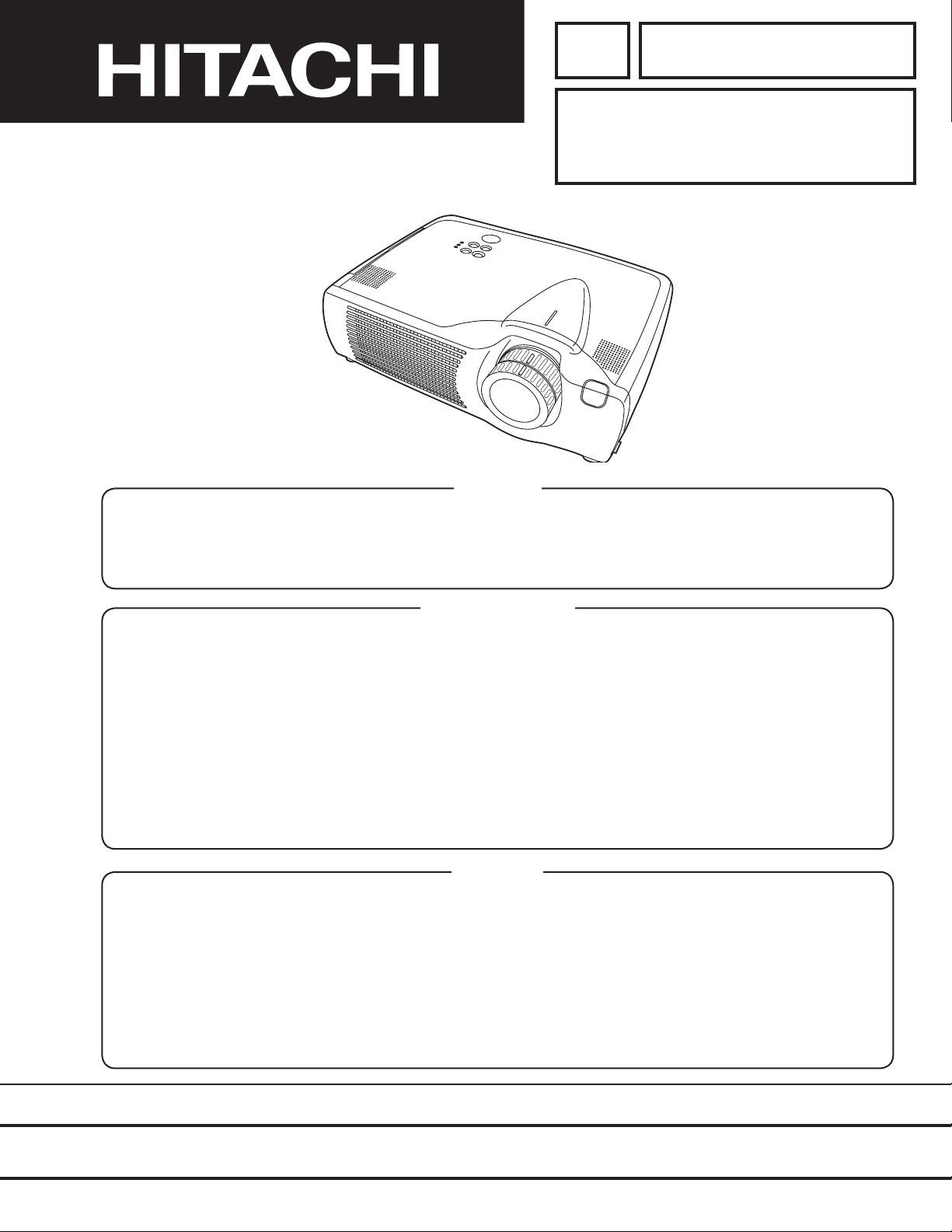
CP-X430W
SERVICE MANUAL
Caution
Be sure to read this manual before servicing. To assure safety from re, electric shock, injury, harmful
radiation and materials, various measures are provided in this HITACHI Multimedia LCD Projector. Be sure to
read cautionary items described in the manual to maintain safety before servicing.
Service Warning
(C7X)
1. When replace the lamp, to avoid burns to your ngers. The lamp becomes too hot.
2. Never touch the lamp bulb with a nger or anything else. Never drop it or give it a shock. They may cause
bursting of the bulb.
3. This projector is provided with a high voltage circuit for the lamp. Do not touch the electric parts of power
unit (main), when turn on the projector.
4. Do not touch the exhaust fan, during operation.
5. The LCD module assembly is likely to be damaged. If replacing to the LCD module assembly, do not hold
the FPC of the LCD module assembly.
6. Use the cables which are included with the projector or specied.
Contents
1. Features --------------------------------------------------- 2
2. Specications--------------------------------------------- 2
3. Names of each part ------------------------------------- 3
4. Adjustment ------------------------------------------------ 5
5. Troubleshooting ---------------------------------------- 11
6. Service points ------------------------------------------ 16
7. Block diagram ------------------------------------------ 23
8. Connector connection diagram -------------------- 24
9. Wiring diagram ----------------------------------------- 25
10.Basic circuit diagram---------------------------------- 30
11.Disassembly diagram--------------------------------- 63
12.Replacement parts list ------------------------------- 65
13.RS-232C communication ---------------------------- 66
SPECIFICATIONS AND PARTS ARE SUBJECT TO CHANGE FOR IMPROVEMENT.
Multimedia LCD Projector
February 2002 Digital Media Systems Division
Page 2

CP-X430W
Liquid crystal
panel
Lamp
RGB
signal
input
Video
signal
input
Signal
output
Drive system
Panel size
Number of pixels
RGB IN
Digital input
Signal
System
System
AUDIO IN
AUDIO IN
VIDEO IN
RGB OUT
AUDIO OUT
S-VIDEO IN
COMPONENT
VIDEO
Audio input
Speaker output
Power supply
Power consumption
Dimensions
Weight
Temperature range
Accessories
TFT active matrix
0.9 inches
1024 (H) × 768 (V)
250W UHB
Video: Analog 0.7Vp-p, 75 terminator
H/V. sync.: TTL level (positive/negative)
Composite sync.: TTL level
D-sub 15-pin shrink jack
Type: T.M.D.S
Amplitude differential signal: DC: 150~1200mV AC: 1.56Vp-p
Amplitude signal: TTL level ("L" : less than 0.8V, "H" : more than 2.0V)
Video: Analog 0.7Vp-p, 75 output impedance (positive)
H/V. sync.: TTL level (positive/negative)
Composite sync.: TTL level
D-sub 15-pin shrink jack
Brightness signal: 1.0Vp-p, 75 terminator
Color signal: 0.286Vp-p (NTSC, burst signal), 75 terminator
0.3Vp-p (PAL/SECAM, burst signal), 75 terminator
Mini DIN 4-pin jack
200mVrms, 47k (max. 3.0Vp-p)
Stereo mini jack
NTSC, NTSC4.43, PAL (BGDHI), SECAM, PAL-M, PAL-N, PAL60
200mVrms, 50k (max. 3.0Vp-p)
RCA jack
1.0Vp-p, 75 terminator
RCA jack
1.0Vp-p, 75 terminator (positive)
0.7Vp-p, 75 terminator (positive)
0.7Vp-p, 75 terminator (positive)
200mVrms, 47k
1W +1W (stereo)
AC100~120V/4.5A, AC220~240V/1.9A
410W
360 (W) × 112.5 (H) × 266 (D) mm
4.5kg (9.92lbs)
Operation : 0~35°C
Storage : -20~60°C
Remote control transmitter × 1
RGB cable × 1
Component cable × 1
Mouse cable (PS/2) × 1
POWER cord × 3
200mVrms, output impedance 1k (max. 3.0Vp-p)
Stereo mini jack
Battery × 2
Carrying bag × 1
Lens cap (set wearing) × 1
User's manual (with Safety Instructions)× 1
1
2
1
2
Y
L
R
CB/CR
PB/PR
480i, 480p, 575i, 720p, 1080i
1. Features
High brightness, High resolution
Compact size, light weight for portability
RS-232C Communication
Auto-adjustment function
2. Specifications
2
Vertical / Horizontal keystone function
P. in P. function
My screen function (User start up screen)
Page 3
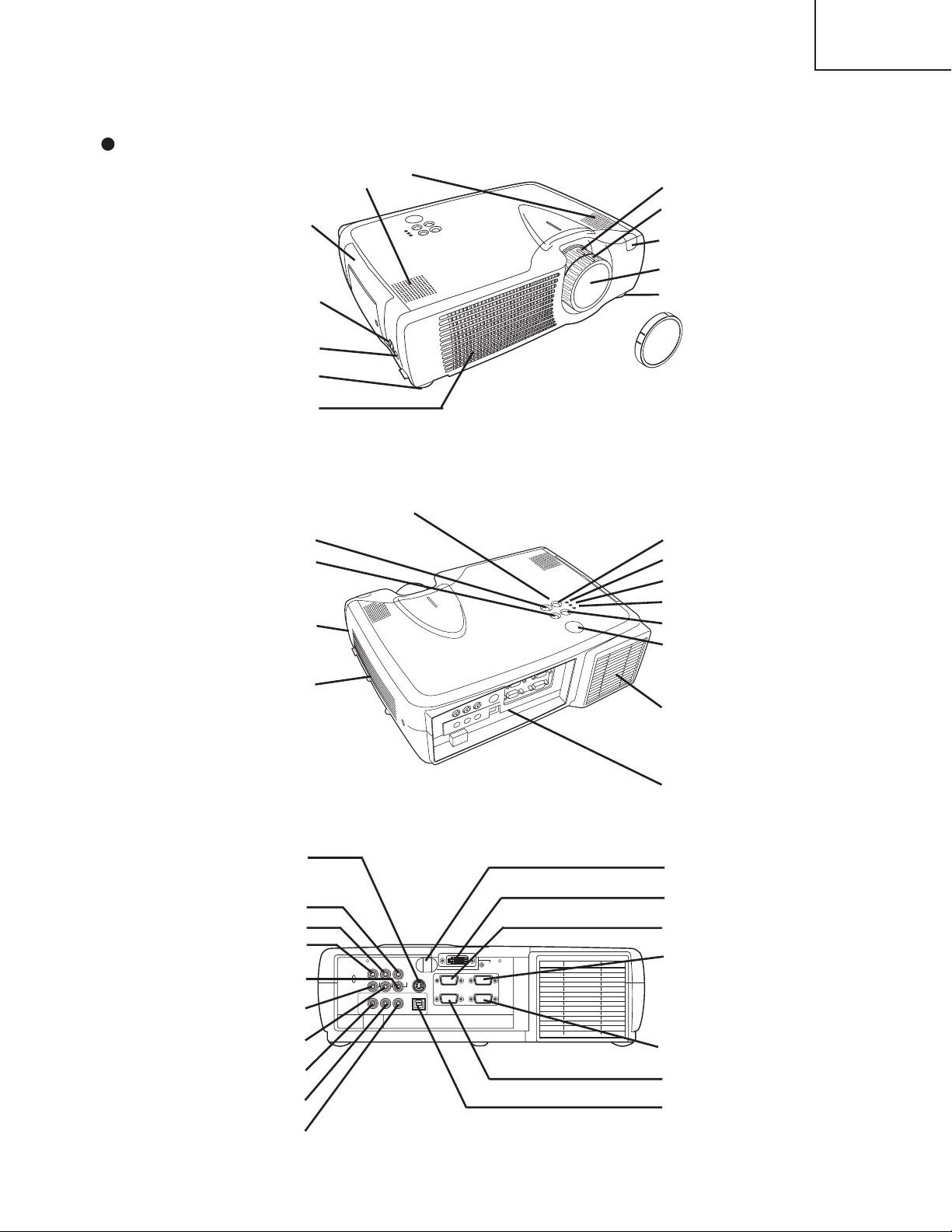
3. Names of each part
Control Panel
AC Inlet
(to the Power Cord)
Power Switch
Foot Adjuster
Ventilation Openings
(Intake)
Zoom Knob
Focus Ring
Remote Control Sensor
Lens
Foot Adjuster
FRONT/LEFT VIEW OF
THE PROJECTOR
Speaker
Carrying Handle
STANDBY/ON Button
KEYSTONE Button
Foot Adjuster Button
Filter Cover
Air Filter and Intake
for the Cooling Fan
INPUT Button
LAMP Indicator
TEMP Indicator
POWER Indicator
RESET Button
MENU Button
Ventilation Openings
(exhaust)
REAR/RIGHT VIEW OF
THE PROJECTOR
Terminal Panel
(Refer below)
TERMINAL PANEL
S-VIDEO Terminal
COMPONENT VIDEO
Y Terminal
C
B/PB Terminal
C
R/PR Terminal
VIDEO IN Terminal
AUDIO IN R
Terminal
AUDIO IN L
Terminal
AUDIO IN 1
Terminal
AUDIO IN 2
Terminal
AUDIO OUT
Terminal
Remote Control Sensor
DVI Terminal
RGB IN 1 Terminal
RGB IN 2 Terminal
CONTROL Terminal
RGB OUT Terminal
USB Terminal
AUDIO
IN
AUDIO
IN
CR/P
R
COMPONENTVIDEO
RGBIN
RGBOUT CONTROL
12
DVI
CB/P
B
Y
R
AUDIOOUT USB1 2
L
VIDEOIN
S-VIDEOIN
( )
Lens Cap
Parts names
CP-X430W
3
Page 4
CP-X430W
S
T
A
N
D
B
Y
/O
N
LASER
BLANK
RGB
VIDEO
AUTO
MENU
MENU SELECT
KEYSTONE
R
ESET
FREE
ZE
PinP
MAGNIFY
POSITION
OFF
VOLUME
MUTE
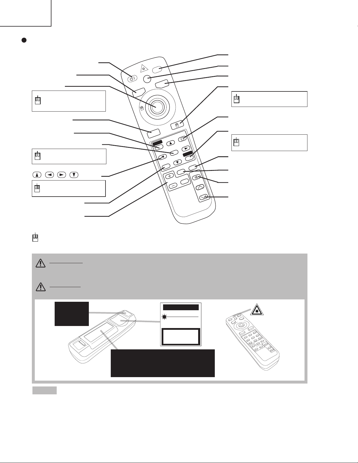
REMOTE CONTROL
TRANSMITTER
• Keep the remote control transmitter away from children and pets.
• Do not give the remote control transmitter any physical impact. Take care not to drop.
• Do not place the heavy objects on the remote control transmitter.
• Do not wet the remote control transmitter or place it on any wet object.
• Do not place the remote control transmitter close to the cooling fan of the projector.
• Do not disassemble the remote control transmitter.
NOTE
STANDBY/ON Button
LASER Button
VIDEO Button
Disk Pad
Used to operate the
mouse shift function and
left click function.
AUTO Button
MENU Button
MENU SELECT Button
Used to click the left
mouse button.
, , , Button
Used to operate the
mouse shift function.
MAGNIFY Button
BLANK Button
RGB Button
MOUSE / RIGHT Button
Used to click the right
mouse button.
RESET Button
Used to click the right
mouse button.
FREEZE Button
MUTE Button
PinP Button
KEYSTONE Button
VOLUME Button
These functions works when the mouse control function is activated. Remember, the POSITION,
BLANK ON and MENU ON functions disable the mouse control function.
WARNING • The laser pointer of the remote control transmitter is used in
place of a finger or rod. Never look directly into the laser beam outlet or point
the laser beam at other people. The laser beam can cause vision problems.
CAUTION
• Use of controls or adjustments or performance of procedures
other than those specified herein may result in hazardous radiation exposure.
POSITION Button
Complies with 21 CFR 1040. 10 and 1040. 11 except for deviations
pursuant to Laser Notice No.50, dated 2001.7.26
SMK CORPORATION
6-5-5 Togoshi Shinagawa-ku, Tokyo, JAPAN 142-8511
MANUFACTURED
Novemver 2001
PLACE OF MANUFACTURER: A
CAUTION
LASER RADIATIONDO NOT STARE INTO BEAM
MAX. OUTPUT: 1mW
WAVE LENGTH
: 650nm
CLASS2 LASER PRODUCT
LASER RADIATION
IEC60825-1 :1993+A1:1997
MAX. OUTPUT: 1mW
WAVE LENGTH: 650nm
DO NOT STARE INTO BEAM
CLASS2 LASER PRODUCT
AVOID EXPOSURE-
LASER RADIATIONS IS
EMITTED FROM THIS
APERTURE
Remote control transmitter
4
Page 5
4. Adjustment
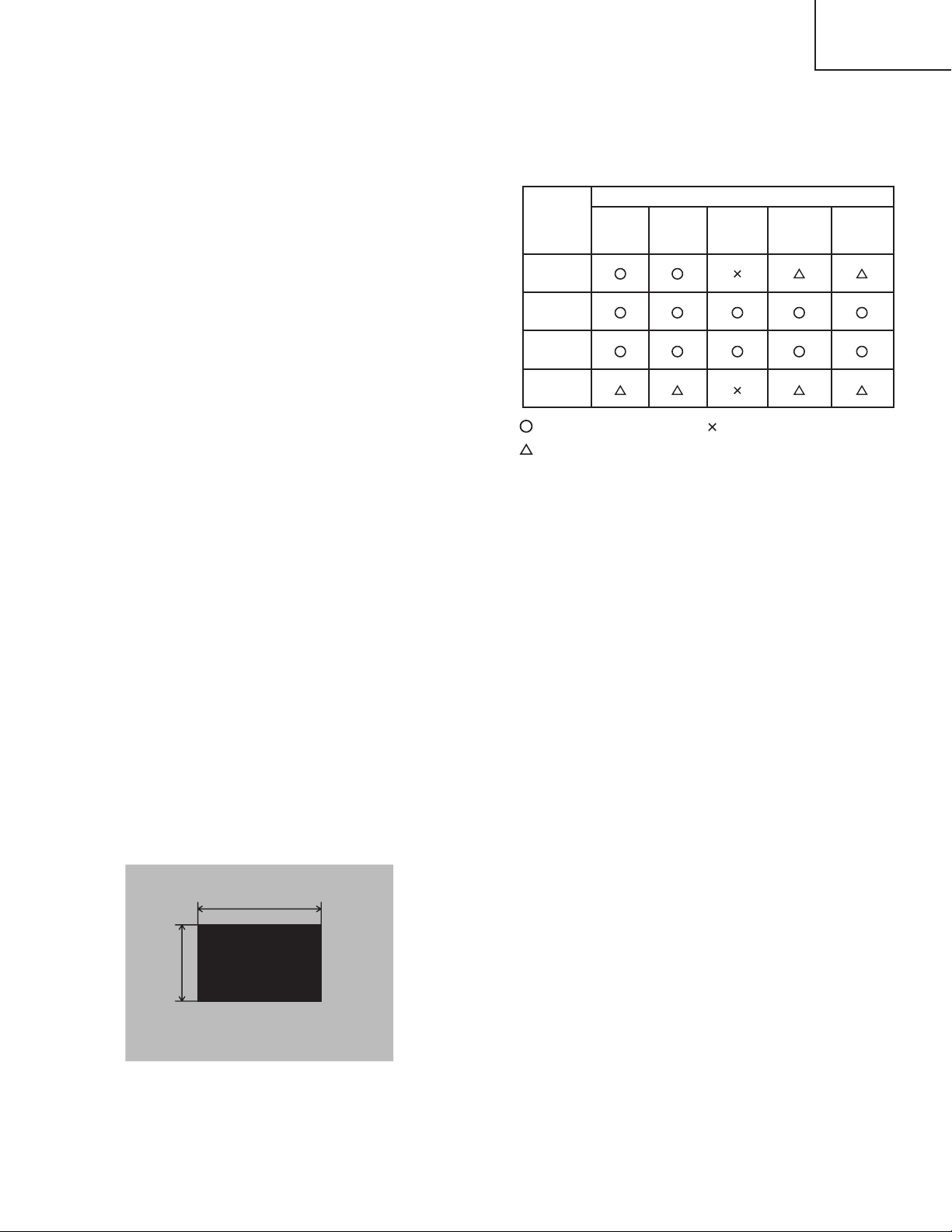
Replaced
part
Ghost
(Chap.4-2)
Flicker
(Chap.4-3)
PSIG
(Chap.4-4)
White
balance
(Chap.4-5)
Color
uniformity
(Chap.4-6)
Dichroic
optics unit
LCD/LENS
prism
assembly
PWB
assembly
drive
Lamp
unit
assembly
Adjustment
30%
30%
112/255
0/255
4-1 Before adjusting
4-4-1 Selection of adjustment
When any parts in the table 4-1 are changed, choose
the proffer adjusting items with the chart.
4-4-2 Setting of condition before adjustment
1. Before starting adjustment, warm up the projector
for about 10 minutes.(Blank white)
2. Set Zoom Wide to Max. And project an image a
distance of more than 40 inches.
3. Normalizing the video adjustment.
(Press the [MENU] button of the Remote control
transmitter to display the Setup menu, and then press
the [RESET] button. And select the [DEFAULT].)
*note : The setup menu is not displayed on with no
signal.
CP-X430W
Table 4-1: Relation between the replaced part and adjustment
:
means need for adjustment.
:
means recommended.
4. Perform all adjustments from the Adjustment menu.
Perform the following operations to display the
Adjustment menu.
a. Press the [MENU] button of the Remote control
transmitter (the Setup menu will appear).
b. Next, press the [RESET] button one time. And
press the [RESET] button again for 5 seconds
or more (the Adjustment menu will appear).
5. Set the normal at OPT-WHISPER in the menu.
6. Set the normal at IMAGE-GAMMA in the menu.
:
means not need for adjustment.
4-2 Ghost adjustment
Signals for internal adjustment
Adjustment procedure
1. Use DAC-P - GHOST - R: in the Adjustment menu
to adjust so that R color ghost is at a minimum.
(Set the adjustment value to default, and then raise
the value. When a light ghost appears to the left of
a vertical line, reduce the value by 2 steps. When a
dark ghost appears to the left of a vertical line,
reduce the value by 3 steps.)
2. In the same way, use DAC-P - GHOST-G: in the
Adjustment menu to adjust so that G color ghost is
at a minimum.
3. In the same way, use DAC-P - GHOST-B: in the
Adjustment menu to adjust so that B color ghost is
at a minimum.
5
Page 6

CP-X430W
30%
30%
112/255
0/255
4-3 Flicker adjustment
Signals for internal adjustment
4-4 P
SIG adjustment (vertical stripe adjustment)
Signals for internal adjustment
(V.COM adjustment)
Adjustment procedure
1. Ma ke th i s a d ju st m en t a f te r c o mp l et in g t h e
adjustment in 4-2 Ghost adjustment.
2. Use DAC-P - V.COM - R: in the Adjustment menu
to adjust so that the flicker at the center of the
screen is less than the flicker at the periphery.
(When the flicker is about the same across the
whole screen, adjust so that the flicker at the
ce n t er o f t h e s c r een i s s o mewhat less than
elsewhere.)
3. In the same way, use DAC-P - V.COM-G: in the
Adjustment menu to adjust the G color flicker.
4. In the same way, use DAC-P - V.COM-B: in the
Adjustment menu to adjust the B color flicker.
Adjustment procedure
1. Ma ke th i s a d ju st m en t a f te r c o mp l et in g t h e
adjustment in 4-3 Flicker adjustment.
2. Use DAC-P - PSIG - G: in the Adjustment menu to
adjust so that the vertical lines spaced every 12
dots are as inconspicuous as possible.
3. Next, use DAC-P - PSIG - B: in the Adjustment
menu to adjust so that the vertical streaks on the
upper of window pattern.
6
Page 7

4-5
White balance adjustment (visual inspection)
Preparations
1. Pe rfor m th es e a dj u st me nt s a ft e r t he P S IG
adjustment described in Section 4-4.
Adjustment procedure
1. First, adjust the G color.
2. Select GAMMA, SUB-CONTRAST, and G: in the
Adjust menu. If the background is white solid,
press the [MENU SELECT] key on the Remote
control transmitter to change to [G] monochrome in
the 28-tone grayscale.
3. Adjust GAMMA, SUB-CONTRAST, and G: in the
Adjust menu so that brightness of 28 steps is best.
4. Don’t adjust GAMMA, SUB-BRIGHT, and G: in the
Adjust menu. Because we want to keep the best
contrast ratio.
5. Then adjust colors R and B.
CP-X430W
2. Reset gamma correction before adjustment.
Place the cursor on [GAMMA] in the Adjustment
menu, pre s s t h e [ RE S ET ] key and se l ec t
[DEFAULT].
6. Select GAMMA, SUB-CONTRAST, and G: in the
Adjust menu. If the background is white solid,
press the [MENU SELECT] key on the Remote
control trasmitter to change to [W] monochrome in
the 28-tone grayscale.
7. Adjust GAMMA, SUB-BRIGHT, R: and B: in the
Adjust menu so that low-brigtness white balance is
best.
8. Adjust GAMMA, SUB-CONTRAST, R: and B: in the
Adjust menu so th at middle-b r ightne ss white
balance is best.
9. Repeat steps 7 to 8 above, and adjust so that
brightness white balance of 28 steps is best.
7
Page 8
CP-X430W
VID-AD
ON
DAC-P GAMMAC. UNIF.
No. 1
R 0
LEVEL
BLACK
MIN MID-L MID-H MAX
STRIPE
OFF
G 0
B 0
Major adjustment lattice point No.
14
12
13
16
15 17
6
4
8
2
1
3
7
5
9
10
11
V/6
H/6 H/3 H/3 H/6
V/3
V/3
V/6
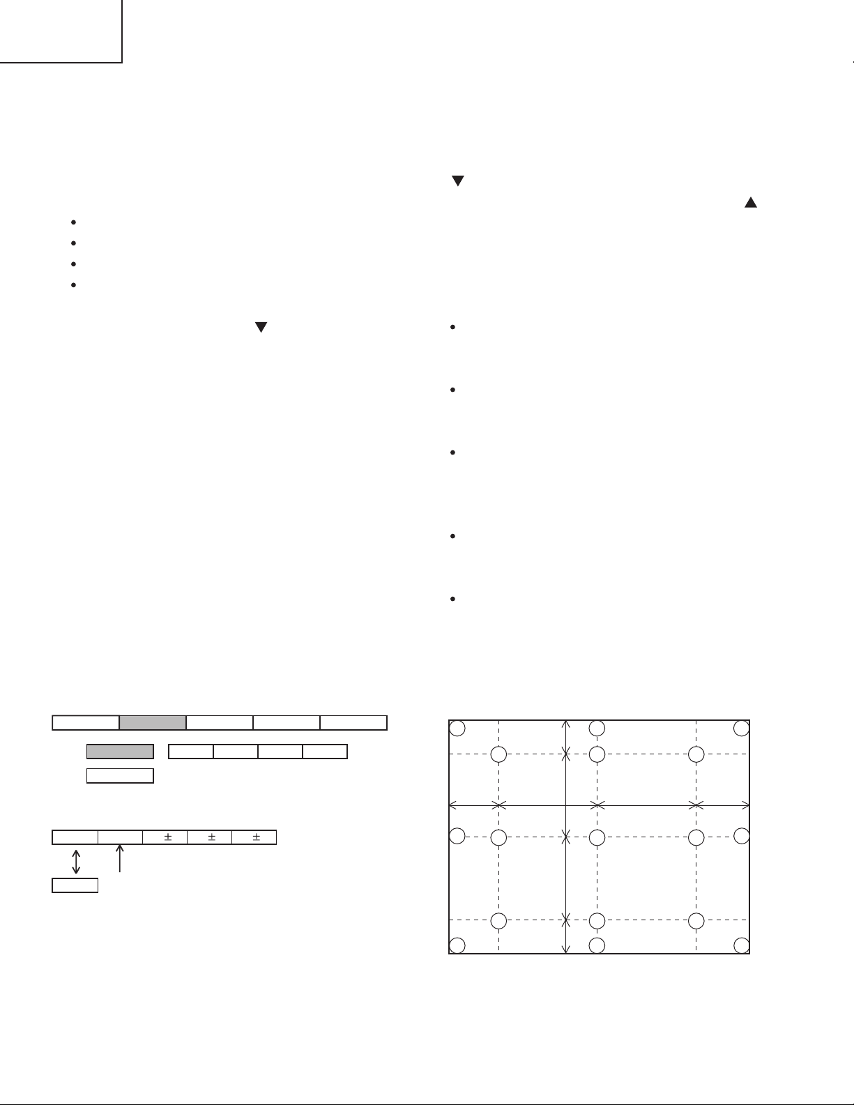
4-6 Color uniformity adjustment
Preparations
1. Perform these adjustments after the white balance
adjustment described in Section 4-5.
2. Make a col o r uniformi t y adjustm e n t fo r the
following four tones.
MIN tone (approx. 10% input signal)
MID-L tone (approx. 21% input signal)
MID-H tone (approx. 50% input signal)
MAX tone (approx. 75% input signal)
3. Place the cursor on the tone to be adjusted in the
Adjust menu and press the [ ] key. This displays
the Adjust Tone menu at the bottom of the screen.
Select the major adjustment lattice point No. and
color, and then adjust them.
4. The major adjustment lattice point numbers (a total
of 17 points) corresponds to the major adjustment
lattice point positions in the diagram on the right.
The color uniformity of the entire screen can be
adjusted by adjusting the white balance for each of
the points starting in order from the low numbers.
5. Adjustment point No.1 should not be adjusted,
because it controls the brightness of the entire
screen.
6. To temporarily turn correction off, place the cursor
on “ON” in the Adjust Tone menu and press the
[ ] key. To turn it on again, place the cursor on
OFF in the Adjust Tone menu and press the [ ]
key.
7. Although this adjustment can also be made using
interna l signals, we will here use the [MENU
SELECT] key on the Remote control transmitter to
select the following two signals.
Solid monochrome adjustment color (use G color
adjustment when a color differential meter is
used).
Soli d white (use for adj ustment oth er than
above).
8. Reset color-shading correction before adjustment.
When 4 tones and all colors are to be reset,
place the cursor on [C.UNIF.] in the Adjustment
menu, pr e s s the [RESET] key and se l ect
[DEFAULT].
When only 1 tone is to be reset, place the cursor
on the tone to be reset, press the [RESET] key
and select [DEFAULT].
Single tone and monochrome resets cannot be
performed.
Adjust menu
Adjust Tone menu
8
Major adjustment lattice point position
Page 9

Adjustment procedure 1
(when a color differential meter is used)
1. First adjust [MID-L] tone [G:].
2. Select adjustment point [No.2][G:].
When the background is not [G] monochrome,
press the [MENU SELECT] key on the Remote
con t rol t ra ns mitt e r to c hang e to s ol id [ G ]
monochrome.
3. Measure the illumination at adjustment points No.
2, No.3, No.10 and No.11.
The values should be:
No.2 = Y2 [lx] No.10 = Y10 [lx]
No.3 = Y3 [lx] No.11 = Y11 [lx]
4. No.2 and No.3 adjustment point have the average
of Y2 and Y3.
Y2 = ( Y2 + Y3 ) / 2 ± 2 [%]
Y3 = ( Y2 + Y3 ) / 2 ± 2 [%]
5. No.10 and No.1 1 adjustment point have the
average of Y10 and Y11.
Y10 = ( Y10 + Y11 ) / 2 ± 2 [%]
Y11 = ( Y10 + Y11 ) / 2 ± 2 [%]
6. Then adjust [MID-L] tone [R] and [B].
When the background is [G] monochrome, press
the [MENU SELECT] key on the Remote control
transmitter to change to solid white.
7. Measure the color coordinates of adjustment point
[No.1] and make a note of them.
Assume that they are x = x1, y = y1.
Note: When the CL-100 color and color difference
meter is us e d , the [ ](delta ) mo d e is
convenient. When adjustment point [No.1]
color coordinate has been selected, set the
slide switch on the side to [ ](delta) while
holding down the [F] button on the front
panel. The measurement shown after this
displays the deviation from measurement
point 1.
8. Measure the color coordinates of measurement
point [No.2] and adjust [No.2][R:] and [B:] so that
the coordinates are as follows.
x = x1 ± 0.005 , y = y1 ± 0.010
CP-X430W
9. Similarly, measure adjustment points [No.3] to
[No.17] and adjust their color coordinates starting
in order from the small number points.
This completes adjustments required for [MIN].
Note: Since excessive correction may lead to a
correction data overview dur ing internal
calculations, use the following values for
reference.
[No.2] to [No.5] ± 40 or less
[No.6] to [No.9] ± 50 or less
[No.10] to [No.13] ± 70 or less
[No.14] to [No.17] ± 120 or less
10. Then adjust [MIN] tone [G] so that the adjustment
data set three times as much as [MID-L] tone [G].
This completes [G] color adjustments.
11. Then adjust [MIN] tone [R] and [B].
Select [No.2] [B:] and press the [MENU SELECT]
key on the Remote control transmitter to change to
solid white.
12. Measure the color coordinates of adjustment point
[No.1] and make a note of them.
Assume that they are x = x1, y = y1.
13. N o w m ea s u r e th e c ol or co o r di na te s o f
measurement point [No.2] and adjust [No.2][R:]
and [B:] so that the coordinates are as follows.
x = x1 ± 0.005 , y = y1 ± 0.010 (Target)
x = x1 ± 0.020 , y = y1 ± 0.040
14. Similarly, measure adjustment points [No.3] to
[No.17] and adjust their color coordinates starting
in order from the small number points.
This completes [MIN] tone adjustments.
15. Now make similar adjustments for [MID-H] tone.
(Adjust [MID-H] tone [G] so that the adjustment
data set half as many as [MID-L] tone [G].)
16. Now make similar adjustments for [MAX] tone.
(Adjust [MAX] tone [G] so that the adjustment data
set half as many as [MID-L] tone [G].)
9
Page 10

CP-X430W
8
3
16
17
9
11
6
14
2
12
15
13
10
7
4
1
5
8
3
16
17
9
11
14
12
15
13
10
4
1
5
6
2
7
8
3
16
17
9
11
6
2
12
13
14
15
10
7
4
1
5
14
12
15
13
10
4
1
5
6
2
7
8
3
16
17
9
11
17
9
15
13
7
5
3
17
9
11
15
13
10
1
5
6
2
7
8
16
17
9
6
12
13
7
4
5
14
12
10
4
1
6
2
8
3
16
17
9
11
3
11
2101
16
14
12
8
6
4
8
4
16
14
12
3
11
2
14
15
10
1
5
7
15 13
17
9
15
13
7
5
3
17
9
11
6
17
9
6
13
7
5
14
12
10
4
6
2
8
16
3
11
2101
16
14
12
8
6
4
8
4
16
14
12
3
11
2
14
15
10
5
7
15
1012
13
15
5
7
12
418
17
13
1
3
11
16
95
17
9
15
13
7
5
3
17
9
11
6
17
9
6
13
7
5
14
12
10
4
6
2
8
16
3
11
2
1
16
14
12
8
4
8
4
16
14
12
3
2
14
15
10
5
7
15
1012
13
5
7
12
4
1
17
13
1
3511
9
11
8
16
15
10
6
Adjustment procedure 2
(visual inspection)
1. First adjust [MIN] tone [G:].
2. Select [No.2] [G:].
If the background is [G] monochrome, press the
[MENU SEL ECT] key on the Rem ote con trol
transmitter to change to solid white.
3. View measurement point [No.2] and [No.3].
Lower the [G] color intensity only of the color point
whose [G] color is more intense than measurement
point [No.1].
4. View measurement point [No.10] and [No.11].
Lower the [G] color intensity only of the color point
whose [G] color is more intense than measurement
point [No.1], and raise the intensity of the point
whose color intensity is lower than measurement
point [No.1].
5. Now adjust the [MIN] tone for colors [R] and [B].
6. View measurement points [No.2], [No.3], [No.10]
an d [No.1 1 ] . Adjust the [ R ] and [ B ] of e ach
measurement point so that they have the same
color as measurement point [No.1].
Adjustment technique:
First, adjust [B:] of the point whose color is to be
adjusted so that it approximates that of [No.1]. If
[R:] is low at this time, the image will have cyan
cast, in which case [R:] is increased. On the other
hand, if [R:] is excessive, the image will have a
magenta cast, in which case [R:] is decreased.
Overall, a cyan cast makes it easy to see color shading.
7. Next, view measurement points [No.4], [No.5],
[No.12], [No.13] and make similar adjustments.
8.
Then adjust measurement points [No.6], [No.7], [No.8],
[No.9], [No.14], [No.15], [No.16] and [No.17].
This completes the [MIN] tone adjustments.
9. Make similar another three tones as described in
steps 1 to 8 above.
No. 2 deviation range No. 10 deviation range No. 3 deviation range No. 11 deviation range
No. 4 deviation range No. 12 deviation range No. 5 deviation range No. 13 deviation range
No. 6 deviation range No. 7 deviation range No. 8 deviation range No. 9 deviation range
No. 14 deviation range No. 15 deviation range No. 16 deviation range No. 17 deviation range
10
Page 11
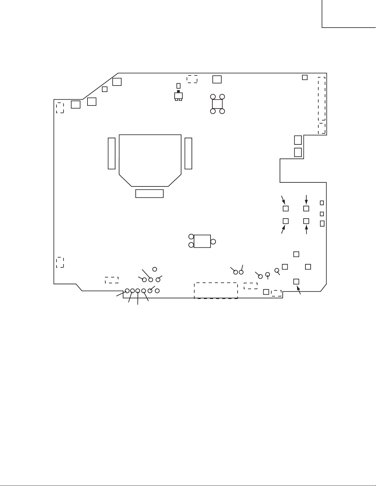
5. Troubleshooting
S201
E803
E802
ESPL
E806
E805
10 1
11
20
1
3
2
L818
Q801
C
E302
I256
ESPR
E800
E811
E808
E809
S302 S303
D302
D301
D303
S307
S308
S304
S305
S306
CH106
CH104
CH102
CH113
EG03
CH112
S309
E807
E101
E804
I102
CHV33
EV01
CHV34
CHV36
CHV35
CHV22
CHV23
CHV26
CHV27
CHV28
CHV29
E801
P502 P702
P602
Check points at trouble shooting
CP-X430W
11
Page 12
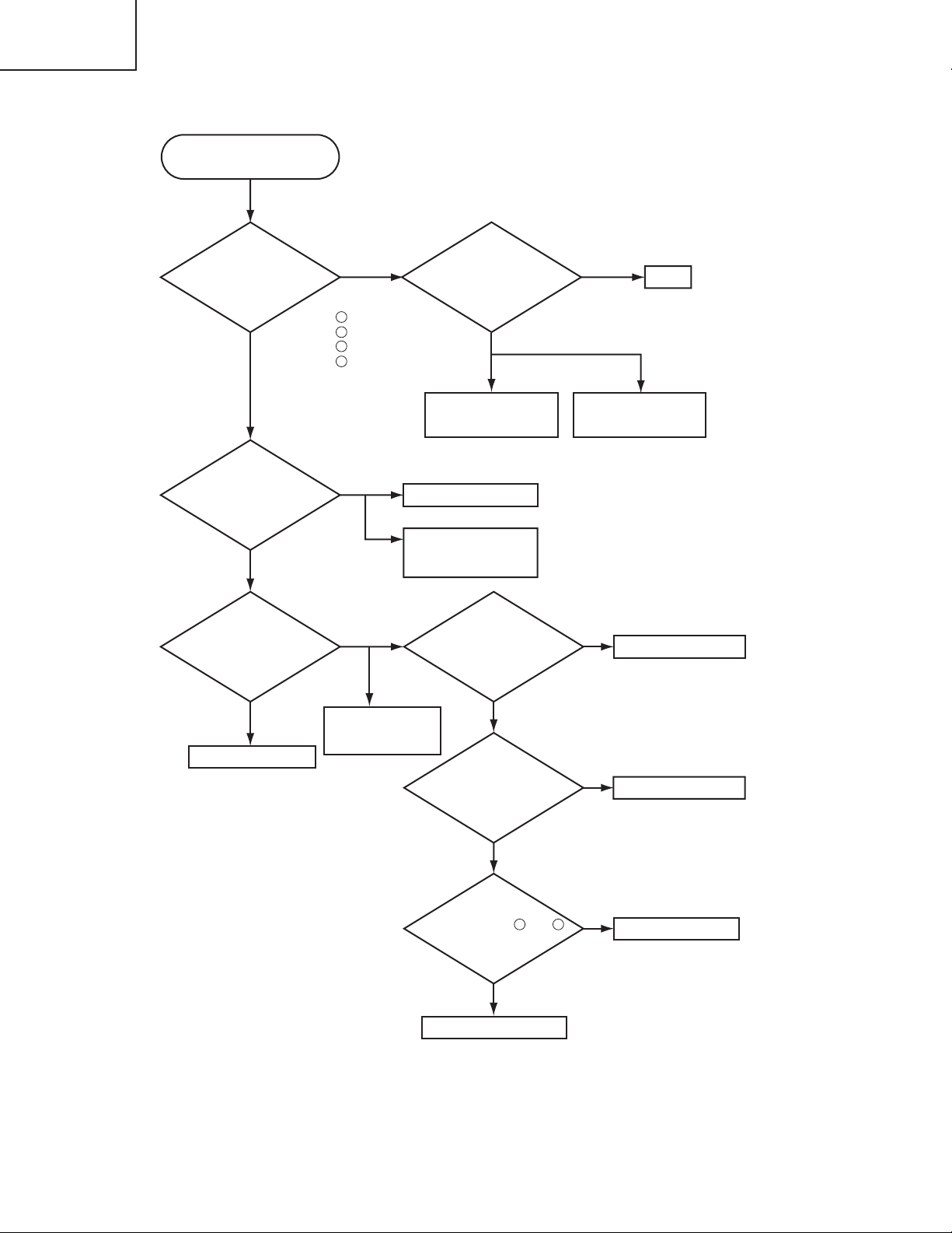
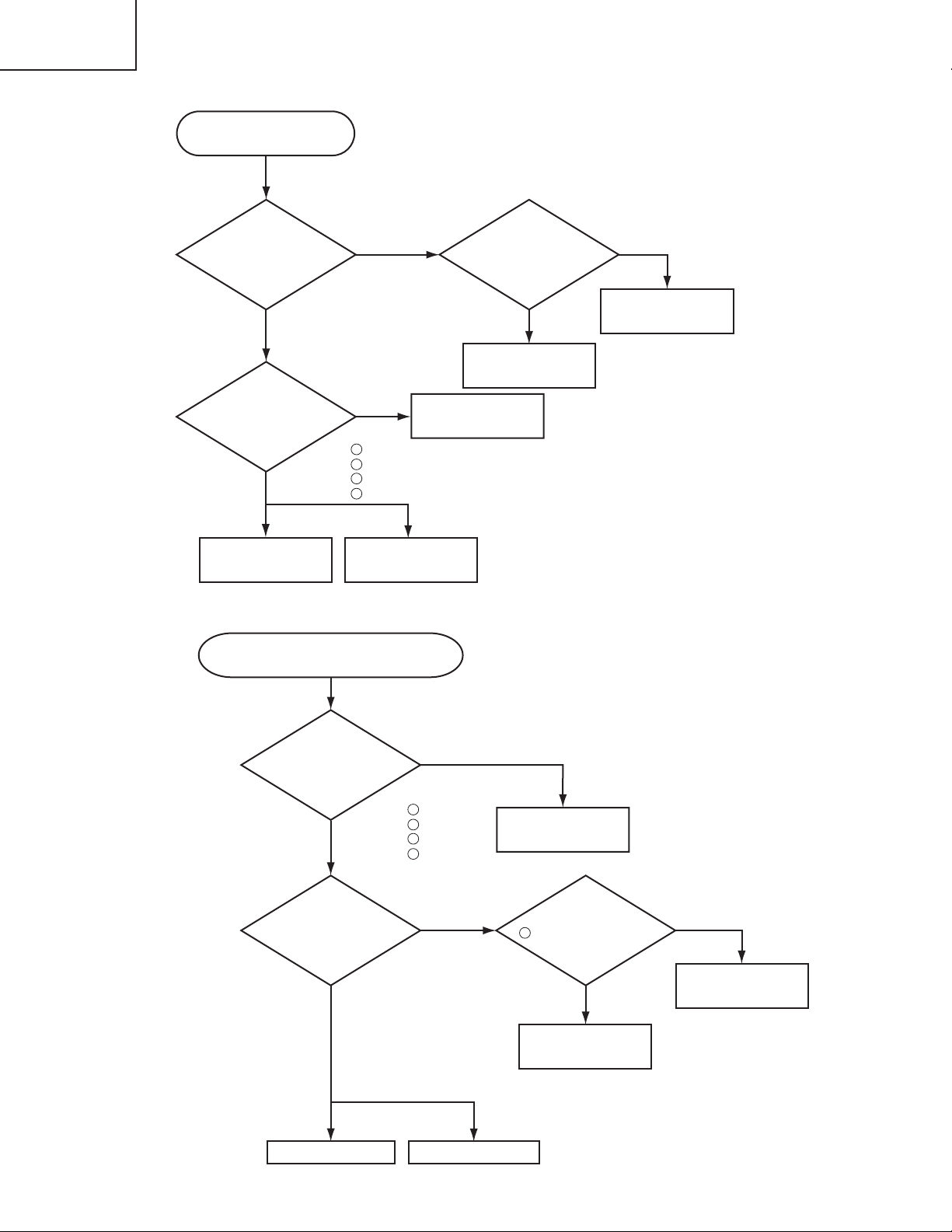
CP-X430W
Power can not be turned on
Are voltage
input on the PWB
assembly Drive at
standby mode?
: +16.5V
: +15V
: +4V
: +6V
E800
E800
E800
E800
Power unit (circuit)
Fuse
on Power unit (circuit)
NO
YES
Disconnect
TSW from Power unit
(circuit). And check
TSW short or
open?
PWB assembly Drive
Lamp
or
Power unit (ballast)
Short
TSW
Open
What is the state of
TEMP indicator
D301?
Not light
DC FAN (for LCD panel)
Lights
Lights
Blinks
DC FAN (exhaust)
or
PWB assembly Sensor
What is the state of
LAMP indicator
D302?
Not light
Blinks
1
4
6
12
Is the LAMP
connection?
OK
Set the LAMP again
Is the
voltage at pin and
of E807 same?
NO
YES
PWB assembly Limit SW
PWB assembly Drive
Is the LAMP COVER
set?
OK
Set the LAMP COVER
NG
NG
1 2
12
Page 13
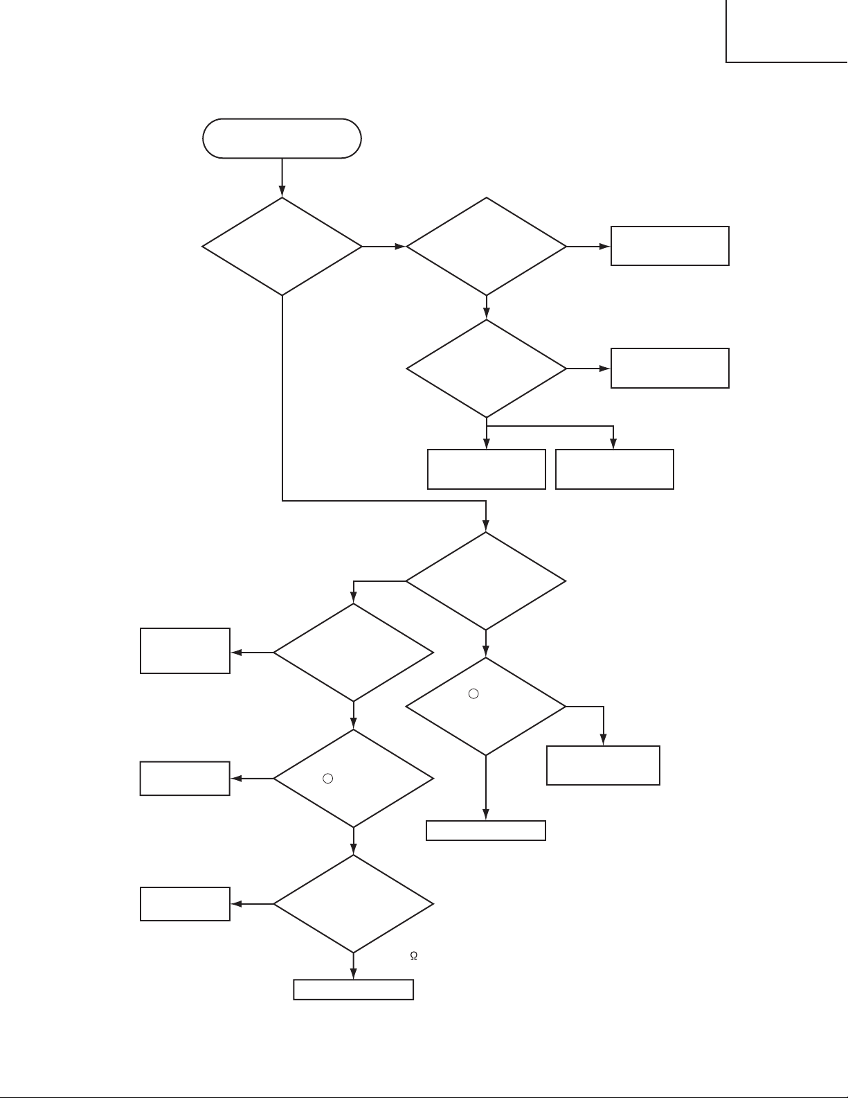
Lamp does not light
What is the state of
LAMP indicator D302
during operation?
Power unit (ballast)
Lamp
PWB assembly Drive
Power unit (ballast)
Light Light
PWB assembly Drive
YES
Not light
NO
YES
Change the lamp.
Does lamp light?
Power unit (circuit)
Not light
NO
What is the state of
TEMP indicator
D301?
Not light
Blinks
PWB assembly Drive
Connect
E302
(for PWB
assembly Sensor)
NO
"L" = 0V
L (0V)
YES
Is the
voltage at collector
of Q801 on the PWB assembly
Drive fixed to "L" during
warming-up?
"L" = 0V
Is E302
(PWB assembly Sensor)
surely connected with
PWB assembly Drive
by the cable?
DC FAN
H (3.3V)
Measure
sure voltage at
the of I256 on the
PWB assembly
Drive.
PWB assembly
Sensor
Infinity
about 10k
Measure
the resistance of
TH950 on the PWB
assembly Sensor at
disconnecting
E302.
Is the voltage
at pin of L818 on
the PWB assembly Drive
set to "L" during
warming-up?
8
2
CP-X430W
13
Page 14
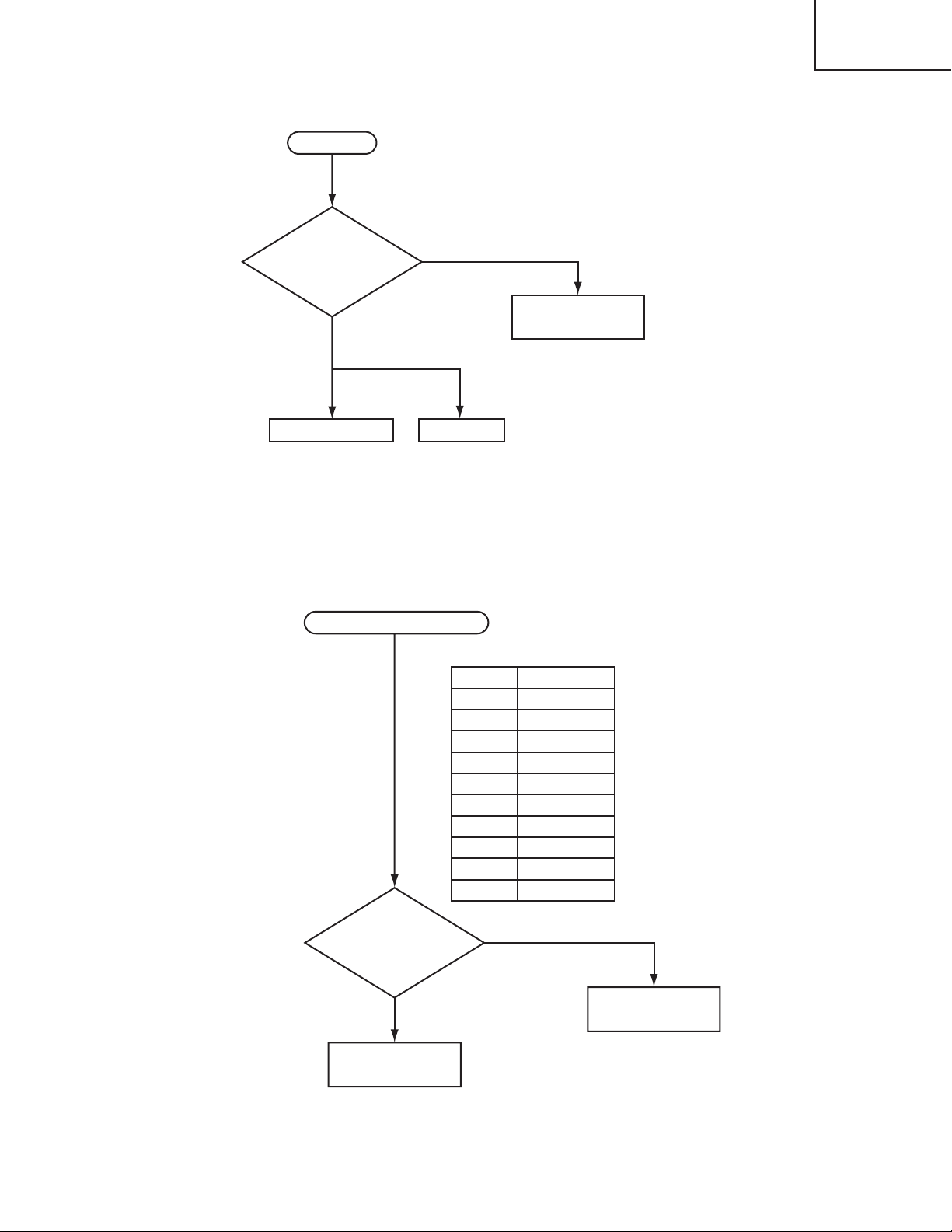
CP-X430W
Picture is not displayed when
the RGB signal is input
Are signal
input at each pin on the
PWB assembly
Drive?
PWB assembly Signal
IC (IS01)
EL4332CS
PWB assembly Drive
LCD panel
NO
YES
Check at operating mode
CH106 : R signal
CH102 : G signal
CH104 : B signal
CH112 : H sync
CH113 : V sync
Power unit
(circuit)
Change the
IS01 on the PWB
assembly Signal is it
repaired?
YES
NO
NO
YES
Are voltage input
at each pin on the PWB
assembly Drive?
: +16.5V
: +15V
: +4V
: +6V
E800
E800
E800
E800
1
4
6
12
Power unit (circuit)
NO
YES
Are voltage
input at each pin on
the PWB assembly
Drive?
PWB assembly Drive LCD module assembly
Are signal
input at these
pins of EV01 on the
PWB assembly
Drive?
Measure
the voltage at pin
of I102 on the PWB
assembly
Drive.
NO
YES
0V
5V
PWB assembly Drive
PWB assembly Signal
Check at operating mode
CHV29 : VIDEO (Composite)
CHV28 : S-VIDEO (Y)
CHV27 : S-VIDEO (C)
CHV34 : Component (Y)
CHV35 : Component (Cb)
CHV36 : Component (Cr)
Picture is not displayed when the VIDEO,
S-VIDEO, Component Signal is input
3
: +16.5V
: +15V
: +4V
: +6V
E800
E800
E800
E800
1
4
6
12
14
Page 15
CP-X430W
PWB assembly Drive Speaker
Check at operating mode
No sound
NO
YES
PWB assembly Signal
Are signal input
at each pin on the PWB
assembly Drive?
CHV26 : Audio (L)
CHV33 : Audio (R)
Are the
signals input at each
pin of EV01 on the PWB
assembly
Drive?
PWB assembly Signal
YES
PWB assembly Drive
NO
CHV22: RX
CHV23: TX
Pin No RS-232C
1
2
3
6
7
9
10
12
13
14
SEL0
RTS
GND
RDP
TDP
Check at operating mode
Can not control to RS-232C
15
Page 16
CP-X430W
E803
E801
E802
E806
E805
E302
P702P502
P602
E800
E811
E808
E809
E804
E807
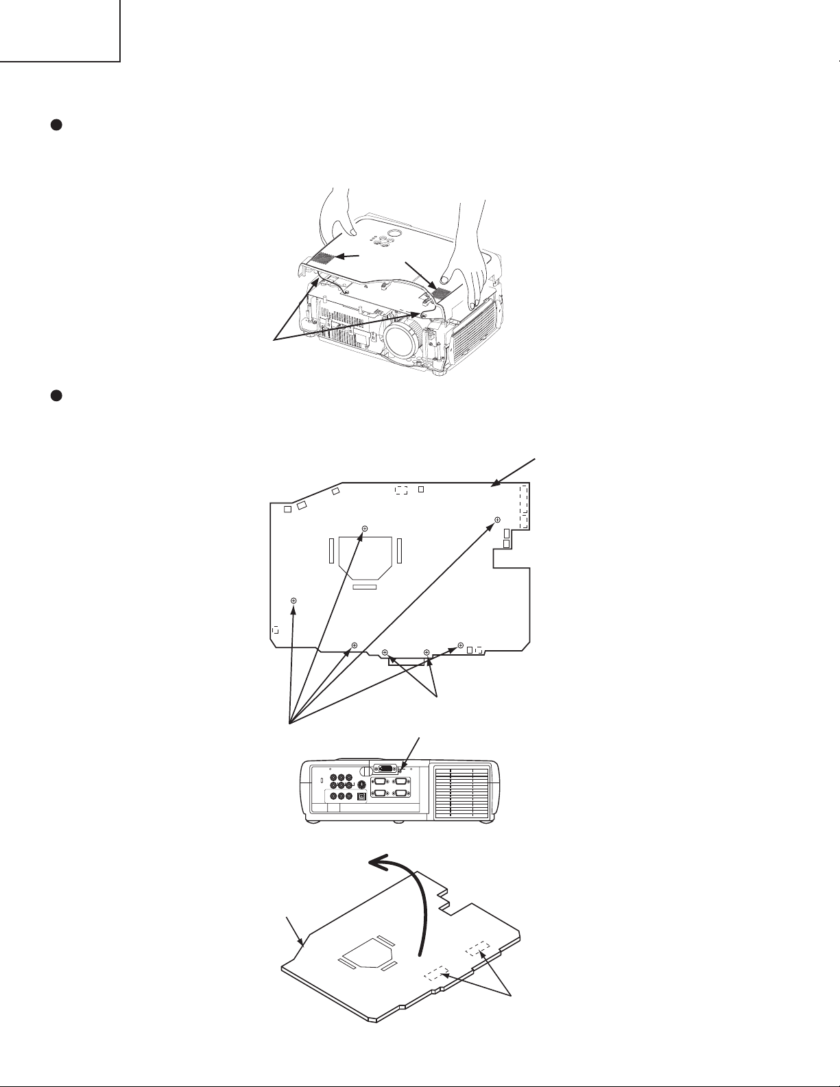
6. Service points
Cautions when removing the Upper case assembly
When you remove the Upper case assembly, avoid to damage wires between speakers on the Upper case
assembly and PWB assembly Drive on the Bottom case assembly.
Speaker
PWB assembly Drive
Wire from Speaker
Cautions when removing the PWB assembly Drive
When removing the PWB assembly Drive, there is a danger of damaging the connectors, connecting cables and
the PWB assembly Signal.
1) Disconnect 15 cables (including 3 flat cables) and remove 6 screws.
PWB assembly Drive
2) Lift up the PWB assembly Drive.
PWB assembly Drive
16
Remove these 5 screws
FRONT
Don’t remove these 2 screws
Remove this screw.
Rear side
Lift up
Disconnect the 2 board-to-board
REAR
connectors.
Page 17

CP-X430W
Before Replacing the LCD / Lens Prism
You should not replace separately the parts of the liquid crystal LCD / Lens Prism because it works properly only
when used together. Therefore, regarding these parts, you can either replace part, LCD / Lens Prism assembly, or
send the whole unit LCD / Lens Prism assembly back to HITACHI, where we will replace the malfunctioning part,
recondition the device and send it back to you. In that case please contact our distributor.
DISTRIBUTOR HITACHI
Do not disassemble the unit
because replacement of separate
parts is not possible.
For repairs of the product, please
contact our distributor.
Replacement of G Panel Reconditioning
Return
Air Filter
Cleaning the Air filter
The air filter should be cleaned as described below at intervals of approximately 100 hours.
1. Switch the projector power supply OFF, and remove the power cord from the power outlet.
2. Clean the air filter with a vacuum cleaner.
G Panel
Replacing the Air filter
Replace the air filter if contamination cannot be removed, or if it is damaged.
1. Remove the filter cover.
2. Remove the old filter.
3. Set the new filter and filter cover.
CAUTION
Switch power OFF and remove the power cord from the power outlet before beginning mainte-
nance work. Please read the separate “SAFETY INSTRUCTIONS” thoroughly to ensure that
maintenance is performed correctly.
Replace the air lter if contamination cannot be removed, or if it is damaged. Contact your dealer
in such case.(Option Air lter assembly : Parts No. NJ06131)
Do not use the equipment with the air lter removed.
When the air lter is clogged with dust etc. the power supply is switched OFF automatically to
prevent the temperature rising inside the projector.
17
Page 18
CP-X430W
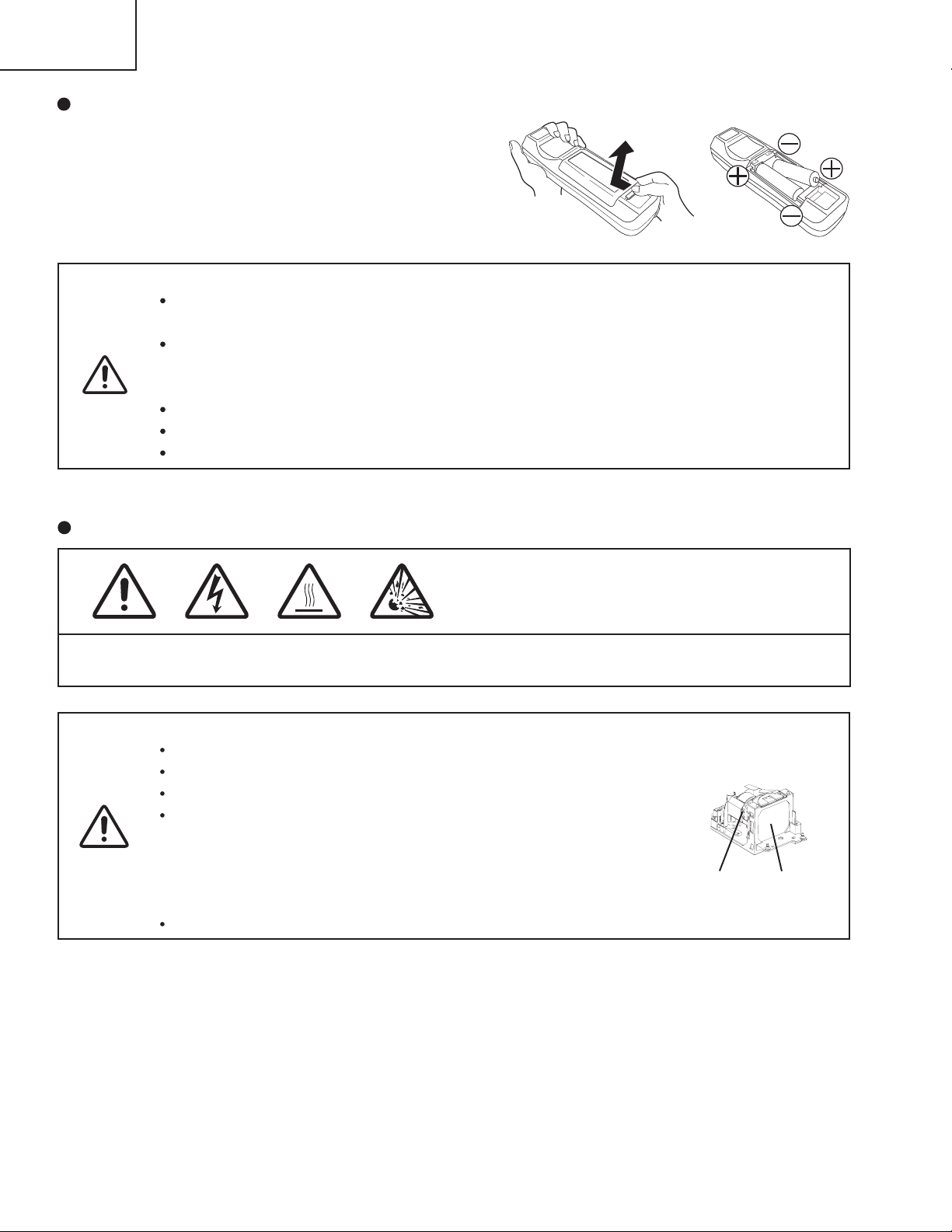
Loading the Batteries
Install the AA batteries into the remote control transmitter.
1. Remove the battery cover.
Push the knob while lifting up the battery cover.
2. Loading the batteries.
Make sure the plus and minus poles are correctly oriented.
3. Close the battery cover.
CAUTION
Use only the specied batteries with this remote control transmitter. Also, do not mix new and old
batteries. This could cause in battery cracking or leakage, which could result in re or personal injury.
When loading the batteries, make sure the plus and minus terminals are correctly oriented as
indicated in the Remote control transmitter. Incorrect orientation could cause battery cracking or
leakage, which could result in personal injury or pollution of the surrounding environment.
When you dispose the battery, you should obey the law in the relative area or country.
Keep the battery away from children and pets.
When not to be used for an extended period, remove the batteries from the Remote control transmitter.
NOTE: Replace the batteries when remote control transmitter operation becomes difficult.
1
2
Lamp (Option Lamp: DT00471)
HIGH VOLTAGE
HIGH TEMPERATURE
HIGH PRESSURE
Before replacing the lamp, switch power OFF, remove the power cord from the power outlet, and wait
approximately 45 minutes until the lamp has cooled. The lamp may explode if handled at high temperatures.
WARNING
For disposal of used lamp, treat according to the instruction of community authorities.
Since the lamp is made of glass, do not apply shock to it and do not scratch it.
Also, do not use old lamp. This could also cause explosion of the lamp.
If it is probable that the lamp has exploded (explosive sound is heard),
disconnect the power plug from the power outlet and ask your dealer to
replace lamp. The lamp is covered by front glass, but in rare cases, the
reector and the inside of the projector may be damaged by scattered broken
pieces of glass, and broken pieces could cause injury when being handled.
Do not use the projector with the lamp cover removed.
Reector
Lamp Life
Projector lamps have a nite life. The image will become darker, and hues will become weaker, after a lamp has
been used for a long period of time.
Replace the lamp if the LAMP indicator is red, or the CHANGE THE LAMP message appears when the projector is
switched ON.
Lamp
Front
glass
NOTE: The LAMP indicator is also red when the lamp unit reaches high temperature. Before replacing the lamp,
switch power OFF, wait approximately 20 minutes, and switch power ON again.
If the LAMP indicator is still red, replace the lamp.
18
Page 19

Replacing the Lamp
1. Switch the projector OFF, remove the power cord from the power outlet,
and wait at least 45 minutes for the unit to cool.
2. Prepare a new lamp.
3. Check that the projector has cooled sufciently, and gently turn it upside
down.
4. Loosen the two screws as shown in the diagram, and remove the lamp
cover.
5. Loosen the three screws, and gently remove the lamp while holding the
grips. Touching the inside of the lamp case may result in uneven coloring.
6. Install the new lamp and tighten the three screws rmly.
Also steadily push the opposite side of the screwed lamp into the unit.
7. Replace the lamp cover in position and tighten the two screws rmly.
8. Gently turn the projector right-side up.
CAUTION
Ensure that screws are tightened properly. Screws not
tightened fully may result in injury or accidents.
Do not use the projector with the lamp cover removed.
CP-X430W
Resetting the Lamp Timer
Reset the lamp timer after replacing the lamp. When the lamp has been replaced after the LAMP indicator is red, or
the CHANGE THE LAMP message is displayed, complete the following operation within ten minutes of switching
power ON. The power will be turned off automatically in over 10 minutes.
1. Switch power ON, and press the RESET button, for approximately three seconds. The ‘LAMP xxxx hr’ message
will appear on the lamp timer on the bottom of the screen.
2. Press the MENU button on the remote control transmitter, or the RESET button on the control panel, while the
lamp timer is displayed. The ‘LAMP xxxx 0 CANCEL’ message will then appear.
3. Press the and select 0, and wait until the timer display is cleared.
NOTE: Do not reset the lamp timer without replacing the lamp. Reset the lamp timer always when replacing the
lamp. The message functions will not operate properly if the lamp timer is not reset correctly.
19
Page 20

CP-X430W
(*1) This message is cleared automatically after approximately three minutes, and
appears every time power is switched ON.
(*2) The unit has a function to turn the power off which will be active when the usage time reaches
2000 hr. However the life of lamp might be much different among lamps, so that it might be
happened that a lamp is cut off before the function is active.
NOTE
Message Contents
CHANGE THE LAMP
AFTER REPLACING LAMP,
RESET THE LAMP TIME.
(*1)
The usage time of lamp will be reaching 2000 hr
shortly.
(*2)
It is recommended to replace the lamp soon. Prepare a
new lamp as a replacement.
CHANGE THE LAMP
AFTER REPLACING LAMP,
RESET THE LAMP TIME.
THE POWER WILL TURN OFF
AFTER
** hr.
(*1)
The usage time of lamp will be reaching 2000 hr shortly.
It is recommended to replace the lamp within * *
hours.
(*2)
It might be happened that the lamp is cut off before * * hr
by any chance. Power will be switched OFF
automatically in * * hours. Replace the lamp as shown in
P.19~20 "Lamp". Always reset the lamp timer after
replacing the lamp.
CHANGE THE LAMP
AFTER REPLACING LAMP,
RESET THE LAMP TIME.
THE POWER WILL
TURN OFF
AFTER 0 hr.
The usage time of lamp is about to reach. Power will be
switched OFF in a few minutes.
(*2)
Switch power OFF immediately and replace the lamp as
shown in P.19~20 "Lamp". Always reset the lamp timer
after replacing the lamp.
NO INPUT IS DETECTED
ON ***
No input signal found.
CHECK THE AIR FLOW
Please remove the obstruction before the suction port.
Check signal input connections and signal sources.
SYNC IS OUT OF RANGE
ON ***
The horizontal or vertical frequency of the input signal is
not within the specified range.
Check the specifications of the equipment and the signal
source.
OSD Message
The messages as described below may appear on the screen at power ON. Take the appropriate measures when
such messages appears.
20
Page 21

CP-X430W
POWER
indicator
LAMP
indicator
TEMP
indicator
Contents
Lights
orange
Turns off Turns off
The Standby mode has been set.
Blinks
green
Turns off Turns off
Warming up. Please wait.
Lights
green
Turns off Turns off
ON. Normal operation possible.
Blinks
orange
Turns off Turns off
Cooling. Please wait.
Blinks red - -
Cooling. Please wait.
The error is found. Take the appropriate measures when the
POWER indicator ceases blinking
Blinks
/Lights red
Lights
red
Turns off
Lamp is not lit.
The interior of the equipment may be too hot. Switch power OFF,
wait 20 minutes until the equipment cools, and check whether the
ventilation openings are blocked, whether the air filter is dirty, or
whether the ambient temperature exceeds 35 °C. And switch
power ON again. Replace the lamp if the same problem occurs.
Blinks
/Lights red
Blinks
red
Turns off
Lamp or lamp cover is not found, or hasn’t been fitted in correctly.
Switch power OFF, and wait for 45 minutes until the equipment
cools. Check fitting of the lamp and lamp cover, and switch power
ON again.
Blinks
/Lights red
Turns off
Blinks
red
The cooling fan is not operating.
Switch power OFF, and wait for 20 minutes until the equipment
cools. Check for foreign matters in the fan, and switch power ON
again.
Blinks
/Lights red
Turns off Lights red
The interior of the equipment is too hot.
Switch power OFF, and wait for 20 minutes until the equipment
cools. Check whether the ventilation openings are blocked,
whether the air filter is dirty, or whether the ambient temperature
exceeds 35 °C. Then switch power ON again.
Lights
green
Blinks
red
Blinks
red
The interior of the equipment is too cool.
Check whether the ambient temperature is below 0°C. Contact your
dealer if the same problem occurs when the ambient temperature is
0~35°C.
When the internal temperature becomes excessive power is switched OFF automatically
for safety reasons, and the indicator is extinguished. Set the power switch to [
O
] and wait for 20
minutes until the equipment has cooled sufficiently.
NOTE
Indicators Message
The POWER indicator, LAMP indicator, and TEMP indicator are lit and blank as follows. Take the appropriate
measures.
21
Page 22

CP-X430W
Setup of a Cooling Fan Speed
When using this projector in the place where altitude is high, we recommend you to set a cooling fan’s speed as
“HIGH”. It is because the cooling efciency of a projector falls and the temperature inside a projector rises easily in
such a place, since the density of air becomes low.
Setting Method of Cooling Fan Speed
1. To display the OSD for cooling fan speed setup:
By the control panel By the remote control transmitter
A proper signal is input
No signal is input
2. Select the “HIGH” on the OSD using the button “ ”. To reset this setup, select the “NORMAL” using the button
“ ”.
3. The OSD will be ended by no operation for 10 seconds or change of input signal. To end immediately, use one of
buttons except buttons “ ”, “ ”, “ ”, “ ”, “RESET”, “MENU SELECT”, “MAGNIFY +/-/OFF”, “FREEZE” (when
no signal is input) or “POSITION” (when no signal is input).
1. Display the menu by the “MENU”
button.
2. Select the “OPT.” on the menu.
3. Continue press the button “ ” rst,
then pr es s the bu t to n “RESET”
together with “ ”, and hold for 3
seconds.
1. Display the menu by the “MENU”
button.
2. Select the “VOLUME” on the menu.
3. Continue press the button “ ” rst,
then pr es s the bu t to n “RESET”
together with “ ”, and hold for 3
seconds.
1. Display the menu by the “MENU”
button.
2. Select the “OPT.” on the menu.
3. Continue pressing the button
“MAGNIFY OFF” for 3 seconds.
1. Display the menu by the “MENU”
button.
2. Select the “VOLUME” on the menu.
3. Continue pressing the button
“MAGNIFY OFF” for 3 seconds.
NOTE:
The “HIGH” mode makes the fan noisy than “NORMAL” mode.
The recall of factory setting sets the fan speed to “NORMAL” mode. You must set the fan speed after recall of
factory setting if you need “HIGH” mode.
22
Page 23

7. Block diagram
0.9"LCD
XGA PANEL
DC POWER
SUPPLY PWB
LAMP POWER
SUPPLY PWB
S/H
DRIVE PWB
CONTROL
PANEL
AC
INPUT
Flash ROM
SP
SUB CPU
PIC
Audio
S-Video
OPTICAL
UNIT
PROJECTION
LENS
Lamp
1M SRAM
64K
EEPROM
DDC
Video
DAC
P/S
COLOR
UNIFORMITY
&
TIMING
GENERATOR
L3E07050
LEVEL
SHIFTER
VIDEO
DECODER
VPC3230Q
TEMP
SENSOR
TEMP
SENSOR
SEL./
COMP.
Component
Video
S/H
IR
RECEIVER
AUDIO_AMP
VOLUME
CONTROL
RGB 1
RGB 2
A/D,PLL
CXA3506
1st_PLL
RGB
A/D
CLAMP
RGB out
Audio Out
SP
SW PWB
DC POWER
REGULATOR
Image_PROCESSOR
PW365-10U
MOUSE
CTL
USB
RS-232C
CTL
DAC
P/S
ext. I/O
DVI
TMDS
RECEIVER
SiI161B
SYNC
SEPARATOR
CXA2151Q
FAN
IR
RECEIVER
REMC PWB
SIGNAL PWB
SIGNAL
SELECTOR
Spread
Spectrum
PLL
Spread Spectrum
X'tal
2nd_PLL
IR
RECEIVER
CP-X430W
23
Page 24

CP-X430W
E950
R/C
(FRONT)
R/C
(UPPER)
S-VIDEO ESM2 EV01 E302
16 RXD 1 1 OUT 1
PWB
17 TXD 2 2 GND 2
assembly
C.VIDEO 18 MOUSE 3 SENSOR
19 REMOTE 4
20 GND 5 E806
21 L.IN 6 1 GND 1
PWB
22 GND 7 2
REMOTE1
2
23 S.CIN 8 P502
1 TEST
3
REMOTE2
3
REMC
24 GND 9 P602 2 COM
25 S.YIN 10 P702 3
VVDD
26 GND 11
4 PCG
27 CVBSIN 12 5 CL R
1
FAN1S
28 GND 13 6 N.C.
E8012LCD-B
FAN
29 9V 14
7
DWN
3
GND
(PANEL-B)
30 9V 15 8 VST
1 5V 16 9 V CK
2 5V 17
10 ENB
3 GND 18 11 N.C.
1
FAN2S
4 Cr/PrIN 19 12 VSSGL
E8022LCD-G FAN
AUDIO-IN 5 GND 20 13 VSS
3
GND (PANEL-G)
(VIDEO-L) 6 Cb/PbIN 21
14 HCK1
4
NC
7 GND 22 15 HCK2
8 Y 23 16 HST
AUDIO-IN(VIDEO-R) 9 GND 24
17 PGT
10 R.IN 25 18 HVDD
1
FAN3S
11 GND 26 19 VSIG12
E8032LCD-R
FAN
AUDIO-IN(RGB1) 12 CLK.A 27
20 VSIG11
3
GND
(PANEL-R)
13 DA TA.A 28 21 VSIG10
AUDIO-IN(RGB2) 14 CS.A 29 22 VSIG9
15 NC 30 23 VSIG8
AUDIO-OUT 24 VSIG7
ESPL1LOUT-
ESM116RGB.R 1 E101 25 VSIG6
2
LOUT+
17 GND 2 26 VSIG5
18 GND 3 27 VSIG4
SPEAKER
19 RGB.G 4 28 VSIG3
20 GND 5 29
21 GND 6
30 VSIG1
ESPR
22 RGB.B 7
1 ROUT-
23 GND 8
2 ROUT+
RGB1-IN 24 GND 9
25 RGB.H-INV 10
SPEAKER
26 RGB.V-INV 11
RGB2-IN 27 R1/R 2 12
E941
28 +5VST 13
E807
29 +5VST 14
1 OUT 1
RGB-OUT 30 GND 15
2 COVER 2
1 GND 16
PWB
assembly
2 +5VST 17
SW.
CONTROL 3 +5VST 18
4 R1/R2 19
E804
5 RGB.V-INV 20
1 FAN4S
6 RGB.H-INV 21
2 OUT FAN
7 GND 22
3 GND (EXHAUST)
8 GND 23
E808
9 RGB.B 24
4 3 2 1
USB(MOUSE) 10 GND 25
11 GND 26
12 RGB.G 27
E800 1 +16.5V 1 CN102
E811 CN103
FAN5S
13 GND 28
2 FAN.GND 2 LAMP FAN
14 GND 29
3 FAN.GND 3 GND (LAMP)
15 RGB.R 30
4 +1 5V 4
NC
5 +15V 5
6 +4V 6
7 +4V 7
8 GND 8
9 GND 9
10 GND 10
11 GND 11
R/C(REAR)
12 +6V
AUDIO +6V
AUDIO GND
POWER 0
12
AC INLET
E805 CN2 CN1 CN101
1 P ON/OFF 1 1 DC IN+ 1
2 GND 2 2 NC 2
3 LAMP.MISS 3 3 DC IN- 3
4 SILENT MODE 4
OUT+
OUT-
CN04
TEMP OUT 1
TEMP RETURN
2
1 1
2 2
3
3
4 VCC
4
VSIG2
31
VSSGR
32
PSIG
E809
1 FAN6S
2 L AMP2 FAN
3 GND
(POWER PWB)
DVI-IN
LAMP UNIT
assembly
POWER
UNIT
POWER
UNIT
(BALLAST)
(CIRCUIT)
PWB assembly DRIVE
PWB assembly
SIGNAL
LCD
PANEL
R/G/B
LAMP
TEMPERATURE
SWITCH
assembly
8. Connector connection diagram
24
Page 25

9. Wiring diagram
Mount sensor board after taking following steps:
Sensor board
CNTH
CNTH
FEB4
TSW
CNPW1
FEB3
CNBAR
FEB1
CNPW2
SKB1
Light
lead
E950
TAP3
Connect CNTH to E950 connector
on sensor board.
Check E950 connector and fix it using
TAP3 (so that connector may not come off).
CN101
CN104
CN102
CN103
Sensor board
Ensure that model
indication of TSW is 90AR1U1N.
1.Power board block wiring
(1) Power board wiring
Before fitting circuit power board into its holder, make sure CNPW1, CNPW2 and TSW cables
are properly connected to CN102, CN103 and CN104 connectors, respectively.
(You cannot connect cables after fitting power board.)
Place the 3 cables through a notch in power board holder leaving no slack in cables.
(Cable slack may touch primary power circuit.)
CN2
Before connecting CNBAR
to CN2 connector, ensure
that it is inserted to the end.
Attach so that hole for securing
SK Binder on FEB3 comes to
connector side as in diagram.
CN1
After connecting CNPWR
to CN1 connector, ensure
to securely lock it.
Put light lead through a notch of ballast holder.
Pull light lead toward outside of holder to leave
no slack in ballast holder, and bind it using
SKB1 as illustrated.
Loop TSW once close to exit point of power
holder cable as in diagram and attach FEB4.
Secure with SK Binder provided.
Attach FEB1 to CNPWR by moving
in the direction shown. Fix it near
the connector using SK binder that
is included in an accessory kit.
Attach FEB3 to CNBAR. Make a loop
at cable outlet on ballast holder as illustrated.
Delete provided SK Binder.
(2) Ballast board block wiring
CNPWR
CP-X430W
25
Page 26

CP-X430W
Wiring when putting ballast board on power board.
Ballast board
Power board
CN101
CN104
CN102
CN103
Ensure that light
lead comes out
of a notch of
ballast holder.
After connecting CNPWR to CN101
connector, ensure to securely lock them.
Connect CNPWR to CN101 connector,
and insert cable into power board
holder as illustrated.
Light
lead
CNPWR
Light
lead
CNBAR
TSW
CNPWR
CNTH
Black coating of light lead
Slide black coating
of light lead.
White coating
of light lead
Ensure that black coating of light lead is
completely within connector.
If not, and when white coating appears
even slightly, slide the black coating
into connector as shown.
(Double coatings are needed for safety.)
Wiring when after putting ballast board on power board.
Clamp CNPW1
and CNPW2
cables at 2 points.
Right view of power board block
(3) Power board block wiring
Fit CNTH around
hook as shown.
Clamp CNPW1 and CNPW2
with PAS1 as in diagram.
Radiation shield
Push CNPWR toward radiation
shield of power board as shown.
Beware that no stress is applied
to power board and ballast
board parts.
CNPW2
CNPW1
PAS1
26
Page 27

CP-X430W
#6402
#6401
Fan for red panel
Fan for green panel
CNLC
Connect CNLC cable to
light switch board
(before mounting board).
CNPW2
CNPW1
#3050
#3054
Light fan
Exhaust fan
#6401
SKB2
SKB2
Approximately
25mm
Fan for blue panel
Light
lead
FEB2
TSW
Screw hole
Before mounting optical unit and power block,
ensure that cables are not caught by any components.
Ensure that cables connected
to fans for red, green and blue
panels came out through the
slit shown.
TAP1
Attach TSW cable
on the curved part
of ballast holder to
TAP1 as shown.
Keep exhaust fan
slits free from cables.
#3055
Exhaust fan
Top View
Side View
CNRM
Connect CNRM
cable to RC board.
Clamp TSW, #3050 and #3054
with PAS3 as in diagram
PAS3
CNBAR
CNTH
2.Wiring when mounting power block and optical unit on bottom case
Connect light lead to
lamp house connector.
Attach FEB2 without
SK binder to light lead,
caring not to cover
the screw hole shown.
(Upper case should
not contact lib.)
To prevent CNBAR from nearing input side of ballast,
pass CNBAR through SK Binder securing hole of
FEB3 as in diagram on right and bind to ballast
holder hook with SKB2. Be sure to pass CNBAR
through SKB2 to allow CNTH to pass through or
beneath binding. Do not over-tighten SK Binder so
FEB3 lifts off ballast holder (as this causes upper
case to lift). As a guide, tighten so that SK Binder ring
comes to about 25mm when crushed.
27
Page 28

CP-X430W
CNPW2
CNPW1
#6401
#6401
#6402
CNRM
rib
CNTH
CNBAR
E302
E805
ESPR
E806
ESPL
E802
E803
E801
E800
E811
E808
E809
#3050
Connect to light
fan, E808.
DRIVE board
Connect to remote control
board cable, E806.
Connect to red
panel fan, E803.
Insert cables #6491
and #6402 into inside
of rib as in diagram,
to prevent making
contact with speaker
fitting during attachment
of upper case.
Connect to green
panel fan, E802.
Connect to blue panel
fan, E801 (back)
Connect to thermistor
cable, E302.
Connect to ballast control
cable, E805 (back).
E807
P502
P602
P702
Connect flexible cable for panel
to flexible connector.
R: to P501, G: to P601, B: to P701
Connect to E800 and E811 at the back
of circuit power cable.
#1358
Clamp 4 cables with
#1358 as shown.
#3054
Connect to exhaust
fan, E809.
CNLC
Connect to light door
switch cable, E807.
E804
#3055
Connect to exhaust fan, E804 (back). Connecting or
inspecting while keeping board lifted is beneficial.
3.Wiring when mounting drive board
Push surplus CNLC and #3055
cableS to the clearance.
28
Page 29

CP-X430W
4.Wiring when attaching upper case
*Attach A83 to upper case according
to assembly drawing.
Hold upper case when you connect or disconnect
cables so that stress may not be applied to cables.
After cable connection, attach upper case while
pushing surplus A84 cable into case.
Beware not to catch cables with front bezel when
attaching it.
Beware not to catch cables with
front bezel when attaching it.
*Attach A84 to upper case according
to assembly drawing.
Upper case
A84
A83
ESPL
ESPR
Beware not to catch cables with
upper case when attaching it.
Hold upper case when you connect
or disconnect cables so that stress
may not be applied to cables.
After cable connection, attach upper
case while pushing surplus A83
cable into case.
Beware not to catch cables with front
bezel when attaching it.
Beware not to cover screw hole with
core, and not to catch cables with
upper case when attaching it.
29
Page 30

CP-X430W
6
5
4
3
2
1
6
5
4
3
2
1
E
DC
B
A
PWB assembly LIMIT SWITCH (C7X)
PWB assembly SENSOR (C7X)
PWB assembly REMOTE CONTROL (C7X)
10. Basic circuit diagram
Parts with hatching are not mounted.
30
Page 31

CP-x430W
6
5
4
6
5
4
3
2
1
3
2
1
POWER UNIT (BALLAST) (C7X)
ABCDEFG
31
32
Page 32

CP-x430W
6
5
4
Out put connector
6
5
4
3
2
1
3
2
1
POWER UNIT (CIRCUIT) (C7X)
ABCDEFG
33
34
Page 33

(female)
CP-X430W
6
5
(female)
4
6
5
4
3
(female)
2
1
3
2
1
PWB assembly SIGNAL 1 (C7X)
ABCDEFG
35
36
Page 34

CP-X430W
6
5
4
6
5
4
3
2
1
3
2
1
PWB assembly SIGNAL 2 (C7X)
ABCDEFG
37
38
Page 35

CP-X430W
6
(male)
5
4
6
5
4
3
mouseserial
RS232C
2
1
3
2
1
PWB assembly SIGNAL 3 (C7X)
ABCDEFG
39
40
Page 36

CP-X430W
6
5
serial
parallel
4
6
5
4
3
2
1
3
2
1
PWB assembly DRIVE 1 (C7X)
ABCDEFG
41
42
Page 37

CP-X430W
6
5
4
6
5
4
3
2
1
3
2
1
PWB assembly DRIVE 2 (C7X)
ABCDEFG
43
44
Page 38

CP-X430W
6
5
4
6
5
4
3
2
1
3
2
1
PWB assembly DRIVE 3 (C7X)
ABCDEFG
45
46
Page 39

CP-X430W
6
5
4
6
5
4
3
2
1
3
2
1
PWB assembly DRIVE 4 (C7X)
ABCDEFG
47
48
Page 40

CP-X430W
6
5
4
6
5
4
3
2
1
3
2
1
PWB assembly DRIVE 5 (C7X)
ABCDEFG
49
50
Page 41

CP-X430W
6
5
4
6
5
4
3
2
1
3
2
1
PWB assembly DRIVE 6 (C7X)
ABCDEFG
51
52
Page 42

CP-X430W
6
5
4
6
5
4
3
2
1
3
2
1
PWB assembly DRIVE 7 (C7X)
ABCDEFG
53
54
Page 43

CP-X430W
6
5
4
6
5
4
3
2
1
3
2
1
PWB assembly DRIVE 8 (C7X)
ABCDEFG
55
56
Page 44

CP-X430W
6
5
4
6
5
4
3
2
1
3
2
1
PWB assembly DRIVE 9 (C7X)
ABCDEFG
57
58
Page 45

CP-X430W
6
5
4
6
5
4
3
2
1
3
2
1
PWB assembly DRIVE 10 (C7X)
ABCDEFG
59
60
Page 46

CP-X430W
6
5
4
6
5
4
3
2
1
3
2
1
PWB assembly DRIVE 11 (C7X)
ABCDEFG
61
62
Page 47

11. Disassembly diagram
2
1
2
3
8
10
11
13
11
12
9
4
6
5
7
CP-X430W
63
Page 48

CP-X430W
14
15
17
19
26
27
28
29
30
18
19
20
21
22
25
24
23
16
64
Page 49

CP-X430W
SYMBOL PARTS SYMBOL PARTS
NO. NO. DESCRIPTION NO. NO. DESCRIPTION
1 QD33871 UPPER CASE ASS'Y 23 JP05395 PWB ASS'Y SENSOR
2 GK00655 SPEAKER 24 2722448 FUSE
3 GS00505 DC FAN(EXHAUST-OUTSIDE) 25 HA01051 POWER UNIT(CIRCUIT)
4 NJ06171 LAMP SWITCH HOUSE 26 JP05388 PWB ASS'Y REMOTE CONTROL
5 GS00771 DC FAN(EXHAUST-INSIDE) 27 JP05392 PWB ASS'Y SIGNAL
6 PV00331 HANDLE 28 CK31602R EL4332CS
7 QD33881 FRONT BEZEL ASS'Y 29 JP05394 PWB ASS'Y LIMIT SWITCH
8 GS00752 DC FAN(LAMP) 30 QD33861 BOTTOM CASE ASS'Y
9 PH31361 FILTER COVER
10 NJ06131 AIR FILTER ASS'Y
11 QJ01061 FRONT FOOT ASS'Y EV00861 POWER SUPPLY CORD (UK TYPE) W/CORE
12 PE00113 RUBBER FOOT EV00881
POWER SUPPLY CORD (UL/CSA TYPE) W/CORE
13 PH31691 LAMP DOOR ASS'Y EV00891
POWER SUPPLY CORD (EUROPE TYPE) W/CORE
14 PC05461 CONTROL BUTTON ASS'Y EW02753 PS/2-2 MOUSE CABLE W/CORE
15 JP05382 PWB ASS'Y DRIVE EW06651 COMPONENT CABLE
16 EA00561R CPC32 CONNECTOR EW06661 RGB-D CABLE(15PIN MALE TO 15 PIN MALE)
17 UE20031 DICHROIC OPTICS UNIT HL01841 REMOTE CONTROL UNIT WITH POINTER
18 GS00755 DC FAN(INTAKE G) NX05741 CLEANING TOOL FOR DUST
19 GS00751 DC FAN(INTAKE R,B) NX05742 COTTON STICK L70
20 UX08051 LCD LENS PRISM ASS'Y QR51551 INSTRUCTION MANUAL S-ASS'Y
21 PH31321 LENS CAP
22 HA01061 POWER UNIT(BALLAST)
12. Replacement Parts list
PRODUCT SAFETY NOTE : Components marked with a have special characteristics important to safety. Before replacing any of there
components, read carefully, the PRODUCT SAFETY NOTICE of this Service Manual. Don't degrade the safety of the projector through
improper servicing.
65
Page 50

CP-X430W
1
23
4
5
6
7
89
10
11
1213
1415
Command data chart
byte_0 byte_1
Action
low high
byte_2 byte_3
Type
low high
byte_4 byte_5
Setting code
low
high
Action Classification Content
Action (byte_0 - 1)
1 SET Change setting to desired value.
2 GET Read projector internal setup value.
4 INCREMENT Increment setup value by 1.
5 DECREMENT Decrement setup value by 1.
6 EXECUTE Run a command.
1
2
3
4
5
6
7
8
9
10
11
12
13
14
15
RD
TD
GND
SELO
RTS
1
2
3
4
5
6
7
8
9
CD
RD
TD
DTR
GND
DSR
RTS
DTS
RI
1
2 3 4 5
6 7
8
9
13. RS-232C communication
(1) Turn off the projector and computer power supplies and connect with the RS-232C cable.
(2) Turn on the computer power supply and, after the computer has started up, turn on the projector power supply.
Projector Computer
Control jack
D-sub 15-pin shrink jack
Communications setting
19200bps, 8N1
1 Protocol
Consist of header (7 bytes) + command data (6 bytes).
2 Header
BE + EF + 03 + 06 + 00 + CRC_low + CRC_high.
CRC_low : Lower byte of CRC ag for command data.
CRC_high : Upper byte of CRC ag for command data.
RS-232C jack
D-sub 9-pin
3 Command data
66
Page 51

CP-X430W
Requesting projector status (Get command)
(1) Send the request code Header + Command data (‘02H’+‘00H’+ type (2 bytes) +‘00H’+‘00H’) from the computer
to the projector.
(2) The projector returns the response code ‘1DH’+ data (2 bytes) to the computer.
Changing the projector settings (Set command)
(1) Send the setting code Header + Command data (‘01H’+‘00H’+ type (2 bytes) + setting code (2 bytes)) from the
computer to the projector.
(2) The projector changes the setting based on the above setting code.
(3) The projector returns the response code ‘06H’ to the computer.
Using the projector default settings (Reset Command)
(1) The computer sends the default setting code Header + Command data (‘06H’+‘00H’+ type (2 bytes)
+‘00H’+‘00H’) to the projector.
(2) The projector changes the specified setting to the default value.
(3) The projector returns the response code ‘06H’ to the computer.
Increasing the projector setting value (Increment command)
(1) The computer sends the increment code Header + Command data (‘04H’+‘00H’+ type (2 bytes) +‘00H’+‘00H’) to
the projector.
(2) The projector increases the setting value on the above setting code.
(3) The projector returns the response code ‘06H’ to the computer.
Decreasing the projector setting value (Decrement command)
(1) The computer sends the decrement code Header + Command data (‘05H’+‘00H’+ type (2 bytes) +‘00H’+‘00H’)
to the projector.
(2) The projector decreases the setting value on the above setting code.
(3) The projector returns the response code ‘06H’ to the computer.
When a command sent by the projector cannot be understood by the computer
When the command sent by the projector cannot be understood, the error command ‘15H’ is returned by the
computer. Some times, the projector ignores RS-232C commands during other works. If the error command ‘15H’ is
returned, please send the same command again.
When data sent by the projector cannot be practice
When the command sent by the projector cannot be practiced, the error code ‘1cH’ +‘xxxxH’ is returned.
When the data length is greater than indicated by the data length code, the projector will ignore the excess data code.
Conversely, when the data length is shorter than indicated by the data length code, an error code will be returned to
the projector.
NOTE:
Operation cannot be guaranteed when the projector receives an undefined command or data.
Provide an interval of at least 40ms between the response code and any other code.
The projector outputs test data when the power supply is switched ON, and when the lamp is lit. Ignore this data.
Commands are not accepted during warm-up.
67
Page 52

CP-X430W
Names Operation type Header
Command data
CRC Action Type Setting code
Blank Color
Set
Red BE EF 03 06 00 3B D3 01 00 00 30 00 00
Orange BE EF 03 06 00 AB D2 01 00 00 30 01 00
Green BE EF 03 06 00 5B D2 01 00 00 30 02 00
Blue BE EF 03 06 00 CB D3 01 00 00 30 03 00
Purple BE EF 03 06 00 FB D1 01 00 00 30 04 00
White BE EF 03 06 00 6B D0 01 00 00 30 05 00
Black BE EF 03 06 00 9B D0 01 00 00 30 06 00
MyScreen BE EF 03 06 00 FB CA 01 00 00 30 20 00
ORIGNAL BE EF 03 06 00 FB E2 01 00 00 30 40 00
Get BE EF 03 06 00 08 D3 02 00 00 30 00 00
Mirror
Set
Normal BE EF 03 06 00 C7 D2 01 00 01 30 00 00
H Inverse BE EF 03 06 00 57 D3 01 00 01 30 01 00
V lnverse BE EF 03 06 00 A7 D3 01 00 01 30 02 00
H&V Inverse BE EF 03 06 00 37 D2 01 00 01 30 03 00
Get BE EF 03 06 00 F4 D2 02 00 01 30 00 00
Freeze
Set
Normal BE EF 03 06 00 83 D2 01 00 02 30 00 00
Freeze BE EF 03 06 00 13 D3 01 00 02 30 01 00
Get BE EF 03 06 00 B0 D2 02 00 02 30 00 00
Menu Color
Set
Red BE EF 03 06 00 7F D3 01 00 03 30 00 00
Orange BE EF 03 06 00 EF D2 01 00 03 30 01 00
Green BE EF 03 06 00 1F D2 01 00 03 30 02 00
Blue BE EF 03 06 00 8F D3 01 00 03 30 03 00
Purple BE EF 03 06 00 BF D1 01 00 03 30 04 00
Transparent BE EF 03 06 00 2F D0 01 00 03 30 05 00
Gray BE EF 03 06 00 DF D0 01 00 03 30 06 00
Get BE EF 03 06 00 4C D3 02 00 03 30 00 00
Startup
Set
ORIGNAL BE EF 03 06 00 0B D2 01 00 04 30 00 00
OFF BE EF 03 06 00 9B D3 01 00 04 30 01 00
MyScreen BE EF 03 06 00 CB CB 01 00 04 30 20 00
Get BE EF 03 06 00 38 D2 02 00 04 30 00 00
Language
Set
English BE EF 03 06 00 F7 D3 01 00 05 30 00 00
Français BE EF 03 06 00 67 D2 01 00 05 30 01 00
Deutsch BE EF 03 06 00 97 D2 01 00 05 30 02 00
Español BE EF 03 06 00 07 D3 01 00 05 30 03 00
Italiano BE EF 03 06 00 37 D1 01 00 05 30 04 00
Norsk BE EF 03 06 00 A7 D0 01 00 05 30 05 00
Nederlands BE EF 03 06 00 57 D0 01 00 05 30 06 00
Português BE EF 03 06 00 C7 D1 01 00 05 30 07 00
Japanese BE EF 03 06 00 37 D4 01 00 05 30 08 00
Get BE EF 03 06 00 C4 D3 02 00 05 30 00 00
Command data chart
68
Page 53

Names Operation type Header
Command data
CRC Action Type Setting code
Magnify
Get BE EF 03 06 00 7C D2 02 00 07 30 00 00
Increment BE EF 03 06 00 1A D2 04 00 07 30 00 00
Decrement BE EF 03 06 00 CB D3 05 00 07 30 00 00
Auto off
Get BE EF 03 06 00 08 86 02 00 10 31 00 00
Increment BE EF 03 06 00 6E 86 04 00 10 31 00 00
Decrement BE EF 03 06 00 BF 87 05 00 10 31 00 00
Brightness Reset Execute BE EF 03 06 00 58 D3 06 00 00 70 00 00
Contrast Reset Execute BE EF 03 06 00 A4 D2 06 00 01 70 00 00
V.Position Reset Execute BE EF 03 06 00 E0 D2 06 00 02 70 00 00
H.Position Reset Execute BE EF 03 06 00 IC D3 06 00 03 70 00 00
H.Size Reset Execute BE EF 03 06 00 68 D2 06 00 04 70 00 00
Color Balance R Reset Execute BE EF 03 06 00 94 D3 06 00 05 70 00 00
Color Balance B Reset Execute BE EF 03 06 00 D0 D3 06 00 06 70 00 00
Sharpness Reset Execute BE EF 03 06 00 C4 D0 06 00 09 70 00 00
Color Reset Execute BE EF 03 06 00 80 D0 06 00 0A 70 00 00
Tint Reset Execute BE EF 03 06 00 7C D1 06 00 0B 70 00 00
Keystone_V Reset Execute BE EF 03 06 00 08 D0 06 00 0C 70 00 00
Keystone_H Reset Execute BE EF 03 06 00 98 D8 06 00 20 70 00 00
Auto Execute BE EF 03 06 00 91 D0 06 00 0A 20 00 00
Blank on/off
Set
off BE EF 03 06 00 FB D8 01 00 20 30 00 00
on BE EF 03 06 00 6B D9 01 00 20 30 01 00
Get BE EF 03 06 00 C8 D8 02 00 20 30 00 00
Error Status Get
BE EF 03 06 00 D9 D8 02 00 20 60 00 00
(Example of Return)
00 00 01 00 02 00 03 00
(Normal) (Cover-error) (Fan-error) (Lamp-error)
04 00 05 00 06 00
(Temp-error) (Air flow-error) (Lamp-Time-over)
Power
Set
OFF
BE EF 03 06 00 2A D3 01 00 00 60 00 00
ON
BE EF 03 06 00 BA D2 01 00 00 60 01 00
Get
BE EF 03 06 00 19 D3 02 00 00 60 00 00
Input Source
Set
RGB1 BE EF 03 06 00 FE D2 01 00 00 20 00 00
RGB2 BE EF 03 06 00 3E D0 01 00 00 20 04 00
DVI BE EF 03 06 00 0E D2 01 00 00 20 03 00
Video BE EF 03 06 00 6E D3 01 00 00 20 01 00
SVideo BE EF 03 06 00 9E D3 01 00 00 20 02 00
Component
BE EF 03 06 00 AE D1 01 00 00 20 05 00
Get BE EF 03 06 00 CD D2 02 00 00 20 00 00
Volume
Get BE EF 03 06 00 31 D3 02 00 01 20 00 00
Increment BE EF 03 06 00 57 D3 04 00 01 20 00 00
Decrement BE EF 03 06 00 86 D2 05 00 01 20 00 00
Command data chart
CP-X430W
69
Page 54

CP-X430W
Names Operation type Header
Command data
CRC Action Type Setting code
Mute
Set
Normal BE EF 03 06 00 46 D3 01 00 02 20 00 00
Mute BE EF 03 06 00 D6 D2 01 00 02 20 01 00
Get BE EF 03 06 00 75 D3 02 00 02 20 00 00
Brightness
Get BE EF 03 06 00 89 D2 02 00 03 20 00 00
Increment BE EF 03 06 00 EF D2 04 00 03 20 00 00
Decrement BE EF 03 06 00 3E D3 05 00 03 20 00 00
Contrast
Get BE EF 03 06 00 FD D3 02 00 04 20 00 00
Increment BE EF 03 06 00 9B D3 04 00 04 20 00 00
Decrement BE EF 03 06 00 4A D2 05 00 04 20 00 00
Color
Balance R
Get BE EF 03 06 00 01 D2 02 00 05 20 00 00
Increment BE EF 03 06 00 67 D2 04 00 05 20 00 00
Decrement BE EF 03 06 00 B6 D3 05 00 05 20 00 00
Color
Balance B
Get BE EF 03 06 00 45 D2 02 00 06 20 00 00
Increment BE EF 03 06 00 23 D2 04 00 06 20 00 00
Decrement BE EF 03 06 00 F2 D3 05 00 06 20 00 00
Keystone_V
Get BE EF 03 06 00 B9 D3 02 00 07 20 00 00
Increment BE EF 03 06 00 DF D3 04 00 07 20 00 00
Decrement BE EF 03 06 00 0E D2 05 00 07 20 00 00
Keystone_H
Get BE EF 03 06 00 E9 D0 02 00 0B 20 00 00
Increment BE EF 03 06 00 8F D0 04 00 0B 20 00 00
Decrement BE EF 03 06 00 5E D1 05 00 0B 20 00 00
Aspect
Set
4:3, Full BE EF 03 06 00 9E D0 01 00 08 20 00 00
16:9 BE EF 03 06 00 0E D1 01 00 08 20 01 00
Small BE EF 03 06 00 FE D1 01 00 08 20 02 00
Get BE EF 03 06 00 AD D0 02 00 08 20 00 00
Display
Position at
16 : 9 or Small
Set
Default BE EF 03 06 00 62 D1 01 00 09 20 00 00
Bottom BE EF 03 06 00 F2 D0 01 00 09 20 01 00
Top BE EF 03 06 00 02 D0 01 00 09 20 02 00
Get BE EF 03 06 00 51 D1 02 00 09 20 00 00
V.Position
Get BE EF 03 06 00 0D 83 02 00 00 21 00 00
Increment BE EF 03 06 00 6B 83 04 00 00 21 00 00
Decrement BE EF 03 06 00 BA 82 05 00 00 21 00 00
H.Position
Get BE EF 03 06 00 F1 82 02 00 01 21 00 00
Increment BE EF 03 06 00 97 82 04 00 01 21 00 00
Decrement BE EF 03 06 00 46 83 05 00 01 21 00 00
H.Size
Get BE EF 03 06 00 B5 82 02 00 02 21 00 00
Increment BE EF 03 06 00 D3 82 04 00 02 21 00 00
Decrement BE EF 03 06 00 02 83 05 00 02 21 00 00
H.Phase
Get BE EF 03 06 00 49 83 02 00 03 21 00 00
Increment BE EF 03 06 00 2F 83 04 00 03 21 00 00
Decrement BE EF 03 06 00 FE 82 05 00 03 21 00 00
Command data chart
70
Page 55

Names Operation type Header
Command data
CRC Action Type Setting code
Sharpness
Get BE EF 03 06 00 F1 72 02 00 01 22 00 00
Increment BE EF 03 06 00 97 72 04 00 01 22 00 00
Decrement BE EF 03 06 00 46 73 05 00 01 22 00 00
Color
Get BE EF 03 06 00 B5 72 02 00 02 22 00 00
Increment BE EF 03 06 00 D3 72 04 00 02 22 00 00
Decrement BE EF 03 06 00 02 73 05 00 02 22 00 00
Tint
Get BE EF 03 06 00 49 73 02 00 03 22 00 00
Increment BE EF 03 06 00 2F 73 04 00 03 22 00 00
Decrement BE EF 03 06 00 FE 72 05 00 03 22 00 00
Video Format
Set
Auto BE EF 03 06 00 9E 75 01 00 00 22 0A 00
NTSC BE EF 03 06 00 FE 71 01 00 00 22 04 00
PAL BE EF 03 06 00 6E 70 01 00 00 22 05 00
SECAM BE EF 03 06 00 6E 75 01 00 00 22 09 00
NTSC 4.43 BE EF 03 06 00 5E 72 01 00 00 22 02 00
M-PAL BE EF 03 06 00 FE 74 01 00 00 22 08 00
N-PAL BE EF 03 06 00 0E 71 01 00 00 22 07 00
Get BE EF 03 06 00 0D 73 02 00 00 22 00 00
HDTV
Set
1080i BE EF 03 06 00 F2 73 01 00 05 22 00 00
1035i BE EF 03 06 00 62 72 01 00 05 22 01 00
Get BE EF 03 06 00 C1 73 02 00 05 22 00 00
PinP Size
Set
off BE EF 03 06 00 FE 22 01 00 00 23 00 00
Large BE EF 03 06 00 6E 23 01 00 00 23 01 00
Small BE EF 03 06 00 9E 23 01 00 00 23 02 00
Get BE EF 03 06 00 CD 22 02 00 00 23 00 00
PinP Position
Set
Upper left BE EF 03 06 00 02 23 01 00 01 23 00 00
Upper right BE EF 03 06 00 92 22 01 00 01 23 01 00
bottom left BE EF 03 06 00 62 22 01 00 01 23 03 00
bottom right BE EF 03 06 00 F2 23 01 00 01 23 02 00
Get BE EF 03 06 00 31 23 02 00 01 23 00 00
PinP Audio ch
Set
RGB BE EF 03 06 00 BA 22 01 00 03 23 00 00
Video BE EF 03 06 00 2A 23 01 00 03 23 01 00
Get BE EF 03 06 00 89 22 02 00 03 23 00 00
PinP Input
Set
Video BE EF 03 06 00 D6 22 01 00 02 23 01 00
S-Video BE EF 03 06 00 26 22 01 00 02 23 02 00
Get BE EF 03 06 00 75 23 02 00 02 23 00 00
Command data chart
CP-X430W
71
Page 56

CP-X430W
Names Operation type Header
Command data
CRC Action Type Setting code
Sync on G
Set
off BE EF 03 06 00 CB D0 01 00 08 30 01 00
on BE EF 03 06 00 5B D1 01 00 08 30 00 00
Get BE EF 03 06 00 68 D1 02 00 08 30 00 00
WHISPER
Set
NORMAL BE EF 03 06 00 3B 23 01 00 00 33 00 00
WHISPER BE EF 03 06 00 AB 22 01 00 00 33 01 00
Get BE EF 03 06 00 08 23 02 00 00 33 00 00
GAMMA
Set
NORMAL BE EF 03 06 00 C7 F0 01 00 A1 30 00 00
CINEMA BE EF 03 06 00 57 F1 01 00 A1 30 01 00
DYNAMIC BE EF 03 06 00 A7 F1 01 00 A1 30 02 00
Get BE EF 03 06 00 F4 F0 02 00 A1 30 00 00
IR Remote Front
Set
off BE EF 03 06 00 FF 32 01 00 00 26 00 00
on BE EF 03 06 00 6F 33 01 00 00 26 01 00
Get BE EF 03 06 00 CC 32 02 00 00 26 00 00
IR Remote Rear
Set
off BE EF 03 06 00 03 33 01 00 01 26 00 00
on BE EF 03 06 00 93 32 01 00 01 26 01 00
Get BE EF 03 06 00 30 33 02 00 01 26 00 00
IR Remote Top
Set
off BE EF 03 06 00 47 33 01 00 02 26 00 00
on BE EF 03 06 00 D7 32 01 00 02 26 01 00
Get BE EF 03 06 00 74 33 02 00 02 26 00 00
Command data chart
• The max. 2 IR remote out of 3 (front, rear and top) can be activated.
NOTE
72
Page 57

MEMO
CP-X430W
73
Page 58

CP-X430W YK No.0520E Digtal Media System Division
QR51101Printed in Japan (S)
 Loading...