

Page 1
CONFIDENTIAL
Dec. 2017
PRODUCT NAME
Hitachi 184 mm (7-1/4”) Circular Saw
Models C 7UR, C 7BUR *For the USA and Canada only
Hitachi 185 mm (7-1/4”) Circular Saw
Model C 7UR *Except for the USA and Canada
CONTENTS
REPAIR GUIDE ---------------------------------------------------------------------------------------------------------------- 1
1. Precautions on disassembly and reassembly ----------------------------------------------------------- 1
• Disassembly ------------------------------------------------------------------------------------------------------ 1
• Reassembly ------------------------------------------------------------------------------------------------------ 6
• Lubrication points and type of lubricant -------------------------------------------------------------------- 8
• Screw tightening torque --------------------------------------------------------------------------------------- 8
• Checking after reassembly ------------------------------------------------------------------------------------- 9
• Wiring diagram ---------------------------------------------------------------------------------------------------10
STANDARD REPAIR TIME (UNIT) SCHEDULES -------------------------------------------------------------------12
Page
C
C 7UR
Overseas Sales Division
Page 2
REPAIR GUIDE
CAUTION: During disassembly and reassembly, and at all other times as well, always exercise
sufficient care in handling to ensure that there is no deviation in the bottom surface
flatness of the base or in its perpendicularity relative to the saw blade.
1. Precautions on disassembly and reassembly
[Bold] numbers in the description below correspond to the item numbers in the parts list and exploded
assembly diagram for the Model C 7UR, and {Bold} numbers correspond to those for the Model C 7BUR.
CAUTION: Prior to disassembly of the circular saw, remove the TCT Saw Blade [12]{12} to protect
the saw blade teeth and yourself.
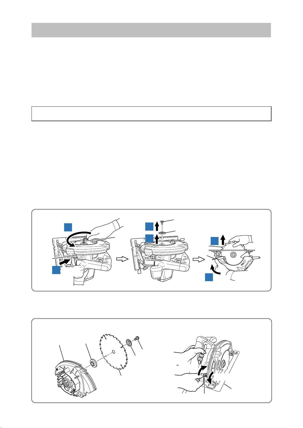
1. Removal of the TCT saw blade
(1) Gently turn the Hex. Socket Hd. Bolt M8 x 15.5 [14]{14} using the accompanying Hex. Bar Wrench 6
mm [503]{502} to lock the Spindle and Gear Set [1]{1} while pushing the Lock Lever [23]{23}.
(2) After locking the Spindle and Gear Set [1]{1}, turn the Hex. Bar Wrench 6 mm [503]{502}
counterclockwise to loosen and remove the Hex. Socket Hd. Bolt M8 x 15.5 [14]{14} and
[13]{13}. Draw the Lever [16] and insert the Lower Guard [8]{8} into the Gear Cover [26]{26} and then
remove the TCT Saw Blade [12]{12}.
NOTE: Be careful not to cut your fingers by the saw blade teeth.
• Removal of the TCT saw blade
[23]{23}
1
(3) Remove Washer (A) [11]{11} from the Spindle and Gear Set [1]{1}. If the Base Plate [65]{62} interferes
with removing Washer (A) [11]{11}, loosen the Lever [66]{63} and adjust to shallower cutting depth.
Loosen
2
Push in
Disassembly
3
[503]{502}
4
[14]{14}
[13]{13}
[12]{12}
[16]{16}
Washer (B)
5
6
Draw
• Removal of washer (A)
[26]{26}
[11]{11}
[12]{12}
[14]{14}
[13]{13}
Loosen
Tighten
[65]{62}
[66]{63}
-1-
Page 3
}
}
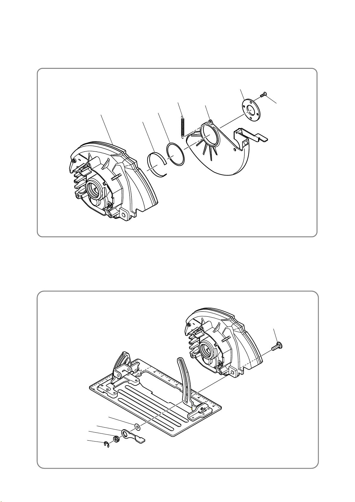
2. Removal of the lower guard
(1) Remove the two Seal Lock Flat Hd. Screws M4 x 10 [10]{10}, then remove the Bearing Cover [9]{9}.
(2) Remove the hook of the Return Spring [7]{7} from the Gear Cover [26]{26} and the Lower Guard [8]{8},
then remove the Lower Guard [8]{8}, Liner [5]{5} and Washer [6]{6}.
• Removal of the lower guard
[26]{26}
[6]{6}
[5]{5}
[7]{7}
[8]{8}
[9]{9}
[10]{10}
3. Removal of the lever
(1) Loosen the Lever [66]{63} and remove the Retaining Ring (E-type) [58]{55}.
(2) Remove the Lever [66]{63}, Lock Nut [59]{56}, Bolt Washer M8 [60]{57}, and Bolt (Square) M8
[29]{29}.
• Removal of Lever
[66]{63
[59]{56
[58]{55}
[29]{29}
[60]{57}
-2-
Page 4
(
)
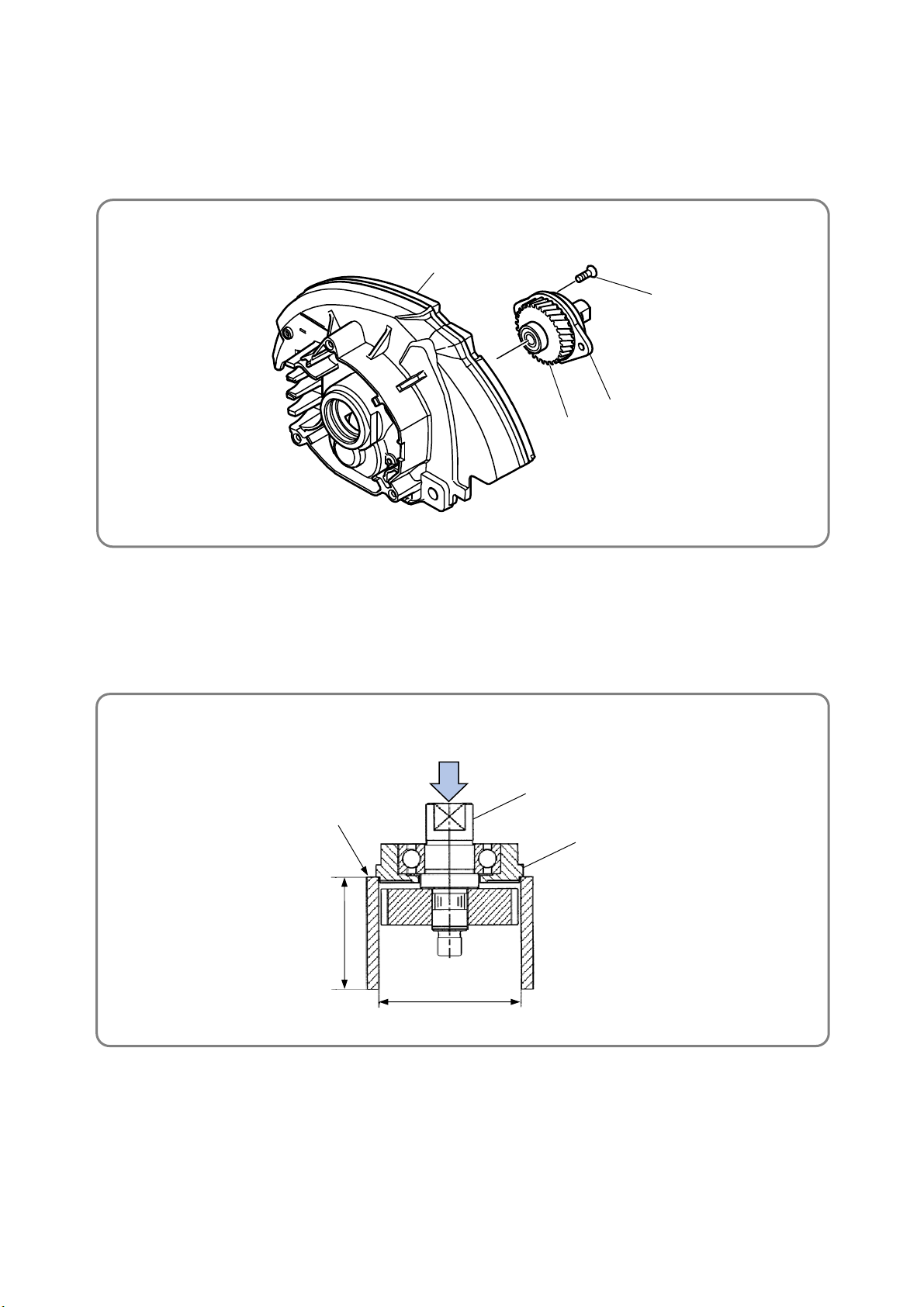
4. Removal of the bearing holder and spindle and gear set
(1) After removing the Lower Guard [8]{8} as described above, loosen the two Seal Lock Flat Hd. Screws
M5 x 14 [3]{3}.
(2) Remove the Bearing Holder [2]{2} together with the Spindle and Gear Set [1]{1} from the Gear Cover
[26]{26}.
• Removal of the bearing holder and spindle and gear set
[26]{26}
[3]{3}
[1]{1}
[2]{2}
5. Separation of the spindle and gear set from the bearing holder
(1) Support the Bearing Holder [2]{2} with an appropriate tubular jig.
(2) Push down on the end of the spindle to separate the Spindle and Gear Set [1]{1} from the Bearing
Holder [2]{2}.
• Separation of the spindle and gear set from the bearing holder
Push
Jig
60 mm
2-23/64"
50 mm
(1-31/32")
[1]{1}
[2]{2}
-3-
Page 5
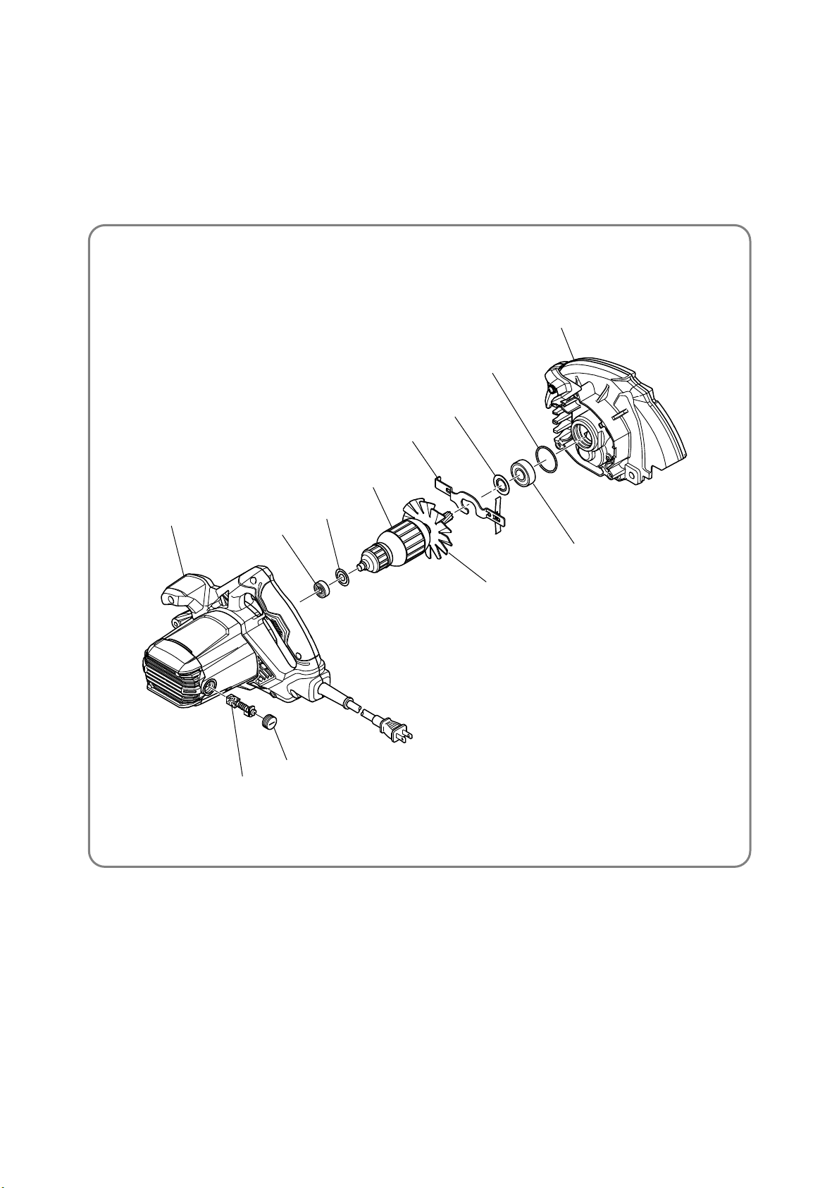
6. Disassembly of the motor unit
(1) Remove the Brush Caps [45]{42} and take out the Carbon Brushes [44]{41}.
(2) Loosen the Machine Screws M5 x 50 [39]{36} and separate the Housing Ass'y [42]{39} from the Gear
Cover [26]{26}. If the Armature [22]{22} is remained in the Housing Ass'y [42]{39}, gently tap the
Housing Ass'y [42]{39} on the edge of the surface where the Gear Cover [26]{26} is mounted with a
wooden or plastic hammer and remove the Armature [22]{22}.
NOTE: Do not hit the fan of the Armature [22]{22}.
• Disassembly of the motor unit
[26]{26}
[34]{32}
[32]{30}
[23]{23}
[53]{56}
[22]{22}
[18]{18}
[17]{17}
[33]{31}
Fan
[45]{42}
[44]{41}
-4-
Page 6
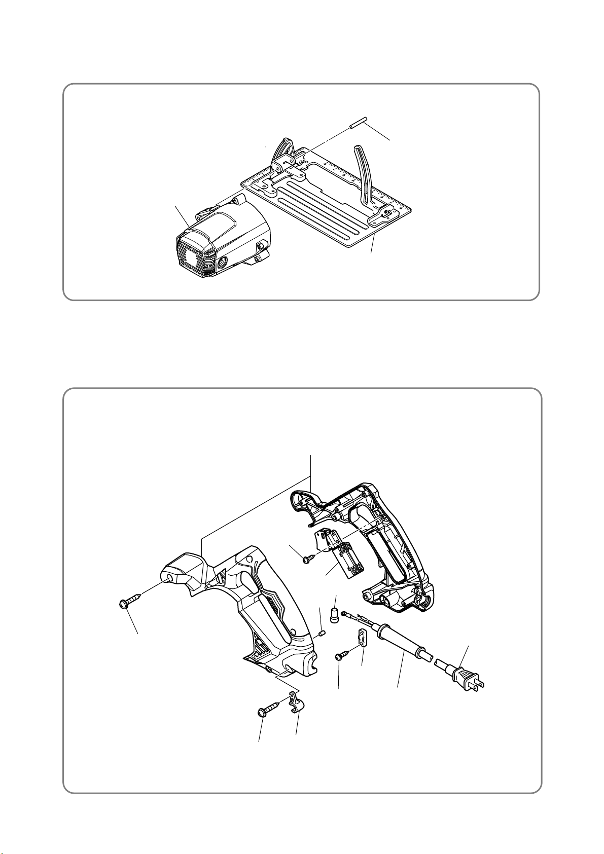
7. Removal of the base ass’y
Extract the Roll Pin D6 x 40 [74]{71} and remove the Base Ass’y [77]{74} from the Housing Ass’y [42]{39}.
• Removal of the base ass'y
[74]{71}
[42]{39}
[77]{74}
8. Disassembly of handle (A).(B) set
(1) Loosen and remove the six Tapping Screws D4 x 20 [38]{35}.
(2) Remove handle (B).
(3) Remove the Switch [48]{45}, Cord [55]{52}, etc. from handle (A).
• Disassembly of handle (A).(B) set
[38]{35}
[47]{44}
[48]{45}
[51]{46}
[56]{53}
{48}
[53]{50}
[52]{49}
[55]{52}
[54]{51}
[38]{35}
[46]{43}
-5-
Page 7

Reassembly
Generally, perform reassembly by reversing the disassembly procedure. However, special attention should
be given to the following items. Refer to “Lubrication points and type of lubricant” on page 8 for the grease
required for reassembly.
1. Reassembly of the power supply unit and its vicinity
Perform wiring according to the wiring diagrams shown on pages 10 and 11 when replacing the Stator Ass'y
[20]{20}, Cord [55]{52}, Noise Suppressor [35] or the Switch [48]{45}. Mount the Cord Clip [53]{50} in the
direction shown in the following figure.
• Mounting the cord clip
For the USA, Canada, and Mexico
[52]{49}
Other than the USA, Canada, and Mexico
[52]
[53]{50}
Protrusion
[53]
Protrusion
2. Mounting the stator ass'y
Press-fit the Stator Ass'y [20]{20} into the Housing Ass'y [42]{39} so that the internal wire of the Stator
Ass'y [20]{20} is positioned to the opposite side of the name plate on the Housing Ass'y [42]{39}. Refer to
the wiring diagrams on pages 10 and 11. After press-fitting, hook the Brush Terminal [19]{19} on the Brush
Holder [43]{40}.
3. Mounting the lock lever
(1) Mount the O-ring [34]{32} into the Gear Cover [26]{26}. Mount the Lock Lever [23]{23} between the fan
of the Armature [22]{22} and Dust Washer (B) [32]{30}. Mount the Ball Bearing [33]{31} to it. Then
carefully mount this assembly into the Gear Cover [26]{26}.
NOTE: Check that both ends of the flat spring on the Lock Lever [23]{23} are properly supported
by the ribs inside the Gear Cover [26]{26}.
(2) After mounting the Lock Lever [23]{23}, push the Lock Lever [23]{23} by hand and check that it returns
to its original position when released.
• Mounting the lock lever
[23]{23}
[22]{22}
[33]{31}
[32]{30}
[26]{26}
[26]{26}
Rib
[34]{32}
[23]{23}
Rib
-6-
Page 8

4. Mounting the bearing holder
(1) Mount the Bearing Holder [2]{2} to the Gear Cover [26]{26} positioning the protrusion on either left or
right side of the Bearing Holder [2]{2} downward.
• Mounting the bearing holder
The Bearing Holder [2]{2} has a protrusion on either left or right side.
[26]{26}
Protrusion
NG
OK
Position of the protrusion
NG
OK
-7-
Page 9

Lubrication points and type of lubricant
Apply specified amount of grease to the following portions.
Grease (Nippeco BC-4)
• Pinion tooth flank of the Armature [22]{22} ····························································· About 1 g
• Gear tooth flank of the Spindle and Gear Set [1]{1} ·················································· About 2 g
• Inside the gear chamber of the Gear Cover [26]{26} ················································· About 6 g
Prepare the following grease as necessary.
Item Registered part name Net weight Code No.
Grease (Nippeco BC-4) Grease (Nippeco BC-4) 75 g 372814
Screw tightening torque
Tightening torque
Location Name of screw or bolt
No.
used
N•m kgf•cm
[2]{2} Bearing Holder [3]{3} Seal Lock Flat Hd. Screw M5 x 14 2 2.7 - 4.1 2.0 - 3.0
[9]{9} Bearing Cover [10]{10} Seal Lock Flat Hd. Screw M4 x 10 2 1.4 - 2.2 1.0 - 1.6
[12]{12} TCT Saw Blade [14]{14} Hex. Socket Hd. Bolt M8 x 15.5 1 7.8 - 11.8 5.8 - 8.7
[16]{16} Lever [15]{15} Machine Screw (W/Washers) M4 x 12 (Black) 1 0.8 - 1.2 0.6 - 0.9
[24]{24} Flow Guide (B) [15]{15} Machine Screw (W/Washers) M4 x 12 (Black) 1 1.4 - 2.2 1.0 - 1.6
[27]{27} Cushion [28]{28} Flat Hd. Screw M6 x 20 1 —*1 —
[40]{37} Tail Cover [38]{35} Tapping Screw (W/Flange) D4 x 20 (Black) 2 1.5 - 2.5 1.1 - 1.8
[46]{43} Cord Holder [38]{35} Tapping Screw (W/Flange) D4 x 20 (Black) 1 1.5 - 2.5 1.1 - 1.84
[56]{53} Handle (A).(B) Set [38]{35} Tapping Screw (W/Flange) D4 x 20 (Black) 5 1.5 - 2.5 1.1 - 1.84
Main body
[42]{39} Housing Ass'y [39]{36} Machine Screw (W/Washers) M5 x 50 (Black) 3 2.7 - 4.1 2.0 - 3.0
[43]{40} Brush Holder [41]{38} Hex. Socket Set Screw M5 x 8 2 0.5 - 1.0 0.4 - 0.74
[44]{41} Carbon Brush [45]{42} Brush Cap 2 0.5 - 1.5 0.4 - 0.74
[48]{45} Switch [47]{44} Tapping Screw (W/Flange) D4 x 10 (Black) 2 1.5 - 2.5 1.1 - 1.84
[53]{50} Cord Clip [52]{49} Tapping Screw (W/Flange) D4 x 16 2 1.5 - 2.5 1.1 - 1.84
[57]{54} Lever (A) [59]{56} Lock Nut 1 1.4 - 2.0 1.0 - 1.5
[66]{63} Lever [59]{56} Lock Nut 1 1.4 - 2.0 1.0 - 1.5
[61]{58} Bevel Stand [63]{60} Seal Lock Flat Hd. Screw M5 x 14 4 2.7 - 4.1 2.0 - 3.0
*1
[72]{69} Step Pin [67]{64} Seal Lock Hex. Socket Set Screw M5 x 6 1 2.7 - 4.1 2.0 - 3.0
[75]{72} Link [76]{73} Seal Lock Flat Hd. Screw M4 x 8 3 1.4 - 2.2 1.0 - 1.6
Base ass'y
[69]{66} U-nut M5 [71]{68} Special Bolt 1 2.7 - 4.1 2.0 - 3.0
*1: Tighten the Flat Hd. Screw M6 x 20 [28]{28} until it is flush with the Cushion [27]{27}.
-8-
Page 10

• Check the following after reassembly.
(1) Adjust the base ass’y angle to 90°±0.5° with the Slotted Hd. Set Screw (Seal Lock) M6 x 8 [64]{61}.
(2) Check that the Base Ass’y [77]{74} operates smoothly. (Adjust the cutting depth and tilt angle.)
(3) Check the switch operation.
(4) Check that the Lower Guard [8]{8} moves smoothly and returns within the operating range (maximum
to minimum cutting depth, tilt angle of 0° to 55°) of the Base Ass’y [77]{74}.
(5) Check the insulation resistance and dielectric strength voltage.
Insulation resistance: 7 MΩ or higher with DC 500 V megohm tester
Dielectric strength: AC 4,000 V/1 minute, with no abnormalities
(6) Check that runout of the saw blade is up to 0.7 mm at 160 mm dia. position.
(7) Check that the direction indicated by the arrow mark on the TCT Saw Blade [12]{12} matches that of the
arrow mark on the Gear Cover [26]{26}.
(8) Perform checking according to the handling instructions.
• Cleaning the cover
Clean the exterior of the tool with a soft cloth moistened with soapy water, and dry thoroughly. Do not use
chloric solvent, gasoline, and thinner for cleaning. Otherwise, the plastic components may be melted.
Checking after reassembly
-9-
Page 11

Wiring diagram
Connect the wires as illustrated in the diagrams below.
Be sure to connect the wires correctly. If the wires are incorrectly connected, the motor may not turn or
other problems could occur.
• Connecting and wiring diagrams of the Model C 7UR for the USA, Canada, and Mexico (120 V)
Switch
Stator coil
White
5±1
Power
source
White
Black
White
Armature
Stator coil
• Connecting and wiring diagrams of the Model C 7UR for the UK (110 V)
Ferrite core
Blue
Power
source
Brown
5±1
Noise suppressor
Ferrite
core
Switch
White
White
Stator coil
Armature
Noise
suppressor
Stator coil
-10-
Page 12

r
r
r
• Connecting and wiring diagrams of the Model C 7UR for countries other than the USA, Canada, and Mexico (230 V to 240 V)
Switch
Stator coil
Brown
Blue
Black
Blue
Switch (Brake)
Powe
source
5±1
Noise suppressor
• Connecting and wiring diagrams of the Model C 7BUR for the USA, Canada, and Mexico (120 V)
Blue
Blue
Armature
Noise
suppressor
Stator coil
Stator
Powe
source
5±1
Connector
Armature
Brake coil
Stator coil
White
Yellow
Black
Connecto
-11-
Page 13

MODEL
C 7UR
C 7BUR
STANDARD REPAIR TIME (UNIT) SCHEDULES
Variable
General Assembly
10 20 30 40 50 60 min.
Work Flow
Handle
(A).(B) Set
Lower Guard
Return
Spring
Base Ass’y
Bevel Plate
Switch
Cord
Cord Armor
Armature
Ball Bearing
6202VV
Ball Bearing
6000VV
Bearing
Bushing
Spindle and
Gear Set
Bearing
Holder
Ball Bearing
6003VV
Gear Cover
Housing
Ass'y
Stator Ass'y
-12-
Page 14

LIST NO. E544
CIRCULAR SAW
Model C 7UR
501
503
3
2
1
502
12
504
505
9
8
7
6
5
4
22
21
11
10
15
16
15
23
25
24
32
26
34
33
2017 · 10 · 23
14
13
(E1)
28
27
29
30
31
20
58
19
57
18
17
35
36
38
37
39
38
43
42
41
40
44
45
38
56
47
48
50
46
49
51
53
52
59
60
62
63
64
54
68
67
61
65
59
58
55
69
70
29
74
71
75
72
73
60
66
77
29
57
73
67
76
75
76
65
Page 15

PARTS C 7UR
DESCRIPTION REMARKS
*
*
*
*
*
*
*
*
*
*
*
*
*
*
*
*
*
*
*
- 2 - 10 - 17
*ALTERNATIVE PARTS
ITEM
NO.
NO.
USED
CODE NO.CODE NO.
1 372782 SPINDLE AND GEAR SET 1
2 372765 BEARING HOLDER 1
3 992013 SEAL LOCK FLAT HD. SCREW M5 X 14 2
4 6003VV BALL BEARING 6003VVCMPS2L 1
5 998887 LINER 1
6 370591 WASHER 1
7 373026 RETURN SPRING 1
8 372758 LOWER GUARD 1
9 302435 BEARING COVER 1
10 990430 SEAL LOCK FLAT HD. SCREW M4 X 10 2
11 324597 WASHER (A) 1
11 372780 WASHER (A) 1 FOR USA,CAN,MEX
11 321639 WASHER (A) 1 FOR AUS,NZL
12 302412 TCT SAW BLADE 185MM-D30 HOLE-NT18 1
12 302411 TCT SAW BLADE 185MM-D20 HOLE-NT18 1 FOR AUS,NZL
12 TCT SAW BLADE 185MM-D16 HOLE-NT24 1 FOR USA,CAN
12 372102 TCT SAW BLADE 185MM-D16 HOLE-NT24 1 FOR MEX
13 324598 WASHER (B) 1
13 320953 WASHER (B) 1 FOR AUS,NZL
14 324662 HEX. SOCKET HD. BOLT M8 X 15.5 1
15 935196
MACHINE SCREW (W/WASHERS) M4 X 12 (BLACK) 2
16 328045 LEVER 1
17 6000VV BALL BEARING 6000VVCMPS2L 1
18 302428 WASHER (A) 1
19 937623 BRUSH TERMINAL 2
20 340983C STATOR ASS'Y 120V 1 INCLUD.19,36
20 340983B STATOR ASS'Y 110V (W/NOISE SUPPRESSOR) 1 INCLUD.19,35,36
20 340983F STATOR ASS'Y 230-240V(W/NOISE SUPPRESSOR) 1 INCLUD.19,35,36
21 372743 FAN GUIDE 1
22 361074U ARMATURE ASS'Y 110V-120V 1 INCLUD.17,18,32,33
22 361074F ARMATURE 230V-240V 1
23 320959 LOCK LEVER 1
24 372768 FLOW GUIDE (B) 1
25 372767 FLOW GUIDE (A) 1
26 372763 GEAR COVER 1
27 337080 CUSHION 1
28 949794 FLAT HD. SCREW M6 X 20 (10 PCS.) 1
29 372774 BOLT (SQUARE) M8 2
30 935196 MACHINE SCREW (W/WASHERS) M4 X 12 (BLACK) 1 EXCEPT FOR USA,CAN
31 372757 DUST COLLECTOR SET 1 INCLUD.30,505 EXCEPT FOR USA,CAN
32 980700 DUST WASHER (B) 1
33 6202VV BALL BEARING 6202VVCMPS2L 1
34 372783 O-RING (I.D. 34.5) 1
35 930039 NOISE SUPPRESSOR 1 FOR EUROPE,GBR,AUS,NZL
36 311741 TERMINAL 2
36 930804 TERMINAL M4.0 (10 PCS.) 2 FOR USA,CAN,MEX
37 NAME PLATE 1
38 301653
39 997841
TAPPING SCREW (W/FLANGE) D4 X 20 (BLACK) 8
MACHINE SCREW (W/WASHERS) M5 X 50 (BLACK) 3
40 372762 TAIL COVER 1
Page 16

PARTS C 7UR
DESCRIPTION REMARKS
*
*
*
*
*
*
*
*
*
*
10 - 17 - 3 -
*ALTERNATIVE PARTS
NO.
USED
CODE NO.
ITEM
NO.
41 938477 HEX. SOCKET SET SCREW M5 X 8 2
42 372759 HOUSING ASS'Y 1 INCLUD.41,43
43 938241 BRUSH HOLDER 2
44 999038 CARBON BRUSH (1 PAIR) 2
45 945161 BRUSH CAP 2
46 370269 CORD HOLDER 1
47 311945
TAPPING SCREW (W/FLANGE) D4 X 10 (BLACK) 1
48 372781 SWITCH 1
49 334379 FERRITE CORE 1 FOR GBR (110V)
50 980063 TERMINAL 2
50 930804 TERMINAL M4.0 (10 PCS.) 2 FOR USA,CAN,MEX
51 931701 BEARING LOCK 1
52 984750 TAPPING SCREW (W/FLANGE) D4 X 16 2
53 937631 CORD CLIP 1
54 953327 CORD ARMOR D8.8 1
54 938051 CORD ARMOR D10.1 1
55 500453Z CORD 1 (CORD ARMOR D10.1)
55 500439Z CORD 1 (CORD ARMOR D8.8) FOR AUS,NZL
55 500435Z CORD 1 (CORD ARMOR D8.8) FOR GBR (230V)
55 500463Z CORD 1 (CORD ARMOR D8.8) FOR GBR (110V)
55 500247Z CORD 1 (CORD ARMOR D8.8) FOR EUROPE
56 373027 HANDLE (A).(B) SET 1
57 372773 LEVER (A) 1
58 670514 RETAINING RING (E-TYPE) FOR D10 SHAFT 2
59 372772 LOCK NUT 2
60 949433 BOLT WASHER M8 (10 PCS.) 2
61 372764 BEVEL STAND 1
62 372770 BEVEL PLATE 1
63 992013 SEAL LOCK FLAT HD. SCREW M5 X 14 4
64 308109
SLOTTED HD. SET SCREW (SEAL LOCK) M6 X 8 1
65 372769 BASE PLATE 1
66 372745 LEVER 1
67 319541
SEAL LOCK HEX. SOCKET SET SCREW M5 X 6 1
68 372778 SPRING (B) 1
69 308387 U-NUT M5 1
70 372776 STOPPER LEVER 1
71 372777 SPECIAL BOLT 1
72 372775 STEP PIN 1
73 372779
SEAL LOCK HEX. SOCKET SET SCREW M5 X 8 1
74 949686 ROLL PIN D6 X 40 (10 PCS.) 1
75 372771 LINK 1
76 328604 SEAL LOCK FLAT HD. SCREW M4 X 8 3
77 372785 BASE ASS'Y 1 INCLUD.29,57-65,67-73,75,76
Page 17

C 7UR
DESCRIPTION REMARKS
*
*
*
*
- 4 - Printed in Japan 10 - 17
(171023N)
*ALTERNATIVE PARTS
STANDARD ACCESSORIES
NO.
USED
CODE NO.
ITEM
NO.
501 372784 CASE 1 EXCEPT FOR USA,CAN
502 302691 GUIDE 1 EXCEPT FOR USA,CAN
503 872422 HEX. BAR WRENCH 6MM 1
504 371108 TOOL BAG 1 FOR USA,CAN
505 LEVER 1 EXCEPT FOR USA,CAN
(SUPPLIED WITH ITEM NO.31)
Page 18

LIST NO. E543
CIRCULAR SAW
Model C 7BUR
501
3
2
1
19
18
17
502
12
11
10
9
8
7
6
5
4
22
21
20
15
16
15
23
54
53
25
24
30
55
56
26
32
31
57
58
59
2017 · 10 · 23
14
13
65
64
(E1)
28
27
29
66
67
29
68
69
71
72
70
60
33
44
35
34
36
35
40
39
38
37
41
42
45
47
46
48
50
49
43
35
51
62
61
57
63
56
55
29
54
64
73
72
52
73
74
62
70
Page 19

PARTS C 7BUR
DESCRIPTION REMARKS
- 2 - 10 - 17
*ALTERNATIVE PARTS
ITEM
NO.
NO.
USED
CODE NO.CODE NO.
1 372782 SPINDLE AND GEAR SET 1
2 372765 BEARING HOLDER 1
3 992013 SEAL LOCK FLAT HD. SCREW M5 X 14 2
4 6003VV BALL BEARING 6003VVCMPS2L 1
5 998887 LINER 1
6 370591 WASHER 1
7 373026 RETURN SPRING 1
8 372758 LOWER GUARD 1
9 302435 BEARING COVER 1
10 990430 SEAL LOCK FLAT HD. SCREW M4 X 10 2
11 372780 WASHER (A) 1
12 TCT SAW BLADE 185MM-D16 HOLE-NT24 1
13 324598 WASHER (B) 1
14 324662 HEX. SOCKET HD. BOLT M8 X 15.5 1
15 935196
MACHINE SCREW (W/WASHERS) M4 X 12 (BLACK) 2
16 328045 LEVER 1
17 6000VV BALL BEARING 6000VVCMPS2L 1
18 302428 WASHER (A) 1
19 937623 BRUSH TERMINAL 2
20 340984C STATOR ASS'Y 120V 1 INCLUD.19,33
21 372743 FAN GUIDE 1
22 361074U ARMATURE ASS'Y 110V-120V 1 INCLUD.17,18,30,31
23 320959 LOCK LEVER 1
24 372768 FLOW GUIDE (B) 1
25 372767 FLOW GUIDE (A) 1
26 372763 GEAR COVER 1
27 337080 CUSHION 1
28 949794 FLAT HD. SCREW M6 X 20 (10 PCS.) 1
29 372774 BOLT (SQUARE) M8 2
30 980700 DUST WASHER (B) 1
31 6202VV BALL BEARING 6202VVCMPS2L 1
32 372783 O-RING (I.D. 34.5) 1
33 930804 TERMINAL M4.0 (10 PCS.) 2
34 NAME PLATE 1
35 301653
36 997841
TAPPING SCREW (W/FLANGE) D4 X 20 (BLACK) 8
MACHINE SCREW (W/WASHERS) M5 X 50 (BLACK) 3
37 372762 TAIL COVER 1
38 938477 HEX. SOCKET SET SCREW M5 X 8 2
39 372759 HOUSING ASS'Y 1 INCLUD.38,40
40 938241 BRUSH HOLDER 2
41 999038 CARBON BRUSH (1 PAIR) 2
42 945161 BRUSH CAP 2
43 370269 CORD HOLDER 1
44 311945
TAPPING SCREW (W/FLANGE) D4 X 10 (BLACK) 1
45 373028 SWITCH 1
46 931701 BEARING LOCK 1
47 930804 TERMINAL M4.0 (10 PCS.) 1
48 959141 CONNECTOR 50092 (10 PCS.) 1
49 984750 TAPPING SCREW (W/FLANGE) D4 X 16 2
50 937631 CORD CLIP 1
Page 20

PARTS C 7BUR
DESCRIPTION REMARKS
69
10 - 17 Printed in Japan - 3 -
(171023N)
*ALTERNATIVE PARTS
STANDARD ACCESSORIES
NO.
USED
CODE NO.
ITEM
NO.
NO.
USED
CODE NO.
ITEM
NO.
51 938051 CORD ARMOR D10.1 1
52 500453Z CORD 1 (CORD ARMOR D10.1)
53 373027 HANDLE (A).(B) SET 1
54 372773 LEVER (A) 1
55 670514 RETAINING RING (E-TYPE) FOR D10 SHAFT 2
56 372772 LOCK NUT 2
57 949433 BOLT WASHER M8 (10 PCS.) 2
58 372764 BEVEL STAND 1
59 372770 BEVEL PLATE 1
60 992013 SEAL LOCK FLAT HD. SCREW M5 X 14 4
61 308109
SLOTTED HD. SET SCREW (SEAL LOCK) M6 X 8 1
62 372769 BASE PLATE 1
63 372745 LEVER 1
64 319541
SEAL LOCK HEX. SOCKET SET SCREW M5 X 6 1
65 372778 SPRING (B) 1
66 308387 U-NUT M5 1
67 372776 STOPPER LEVER 1
68 372777 SPECIAL BOLT 1
372775 STEP PIN 1
70 372779
SEAL LOCK HEX. SOCKET SET SCREW M5 X 8 1
71 949686 ROLL PIN D6X40 (10 PCS.) 1
72 372771 LINK 1
73 328604 SEAL LOCK FLAT HD. SCREW M4 X 8 3
74 372785 BASE ASS'Y 1 INCLUD.29,54-62,64-70,72,73
DESCRIPTION REMARKS
501 371108 TOOL BAG 1
502 872422 HEX. BAR WRENCH 6MM 1
 Loading...