

Page 1
TECHNICAL DATA
AND
SERVICE MANUAL
CIRCULAR SAWS
C 6SF, C 7SF
C 6MF, C 7MF
SPECIFICATIONS AND PARTS ARE SUBJECT TO CHANGE FOR IMPROVEMENT
LIST Nos. C 6SF: 0597 C 6MF: 0599
C 7SF: 0598 C 7MF: E501
Feb. 2004
C
MODELS
C 6SF, C 6MF
C 7SF, C 7MF
Hitachi
Power Tools
Page 2
REMARK:
Throughout this TECHNICAL DATA AND SERVICE MANUAL, a symbol(s)
is(are) used in the place of company name(s) and model name(s) of our
competitor(s). The symbol(s) utilized here is(are) as follows:
Symbol Utilized
Competitor
Company Name
Model Name
C --- 1 MAKITA
5606B
C 6SF, C 6MF
Symbol Utilized
Competitor
Company Name
Model Name
C --- 2 MAKITA
5806B
C 7SF, C 7MF
Page 3

Page
CONTENTS
1. PRODUCT NAME.............................................................................................................................. 1
2. MARKETING OBJECTIVE ................................................................................................................ 1
3. APPLICA TIONS................................................................................................................................. 1
4. SELLING POINTS ............................................................................................................................. 1
4-1. Selling Point Descriptions ...................................................................................................................2
5. SPECIFICATIONS ............................................................................................................................. 3
6. COMPARISONS WITH SIMILAR PRODUCTS ................................................................................. 4
7. PRECAUTIONS IN SALES PROMOTION ........................................................................................ 4
7-1. Handling Instructions ..........................................................................................................................4
8. PRECAUTIONS IN DISASSEMBLY AND REASSEMBLY ............................................................... 5
8-1. Disassembly .......................................................................................................................................5
8-2. Reassembly ........................................................................................................................................8
8-3. Insulation Tests .................................................................................................................................11
8-4. Deflection of Saw Blade....................................................................................................................11
8-5. Cleaning the Case ............................................................................................................................ 11
9. STANDARD REPAIR TIME (UNIT) SCHEDULES .......................................................................... 12
Assembly Diagram for C 6SF
Assembly Diagram for C 6MF
Assembly Diagram for C 7SF
Assembly Diagram for C 7MF
Page 4
--- 1 ---
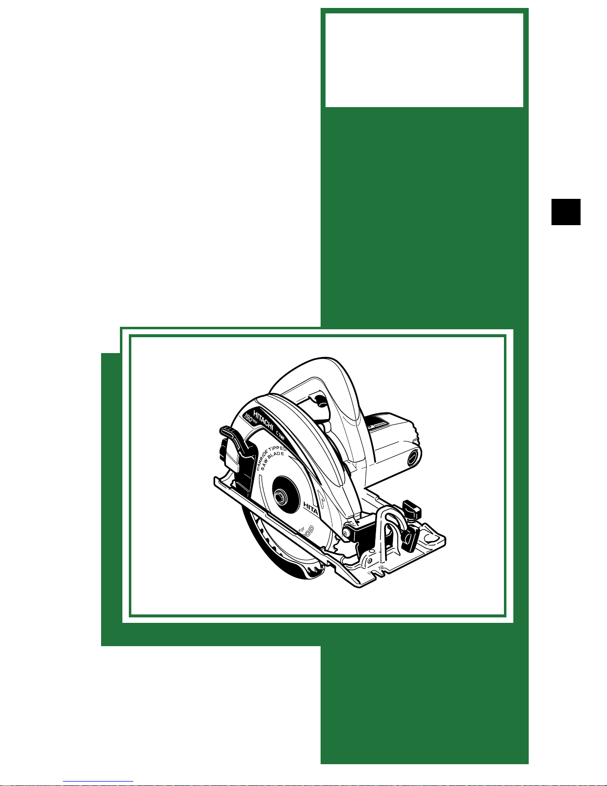
1. PRODUCT NAME
Hitachi Circular Saw, Model C 6SF [165 mm (6-1/2") ]
Hitachi Circular Saw, Model C 6MF [165 mm (6-1/2") ]
Hitachi Circular Saw, Model C 7SF [190 mm (7-1/2")]
Hitachi Circular Saw, Model C 7MF [190 mm (7-1/2")]
2. MARKETING OBJECTIVE
Circular saw market in the South-East Asian countries are mainly demanding the heavy-duty machines for
professionals. However, potential demands for reasonably priced and light-duty machines are seemed to be
strong. We will expand selling the circular saws with reasonable price and high performance for South-East Asian
countries to find a new market. The key features are as follows:
(1) Provided with parallel adjustment system
(2) Adopting lower guard made of plastic not to hurt the material to be cut
(3) Adopting base made of aluminum which is strong and precise (only Models C 6MF and C 7MF)
3. APPLICA TIONS
Cutting of various wood materials
Cutting of decorated laminate plates, thin plastic plates, soft construction materials (using the saw blade for
plastic)
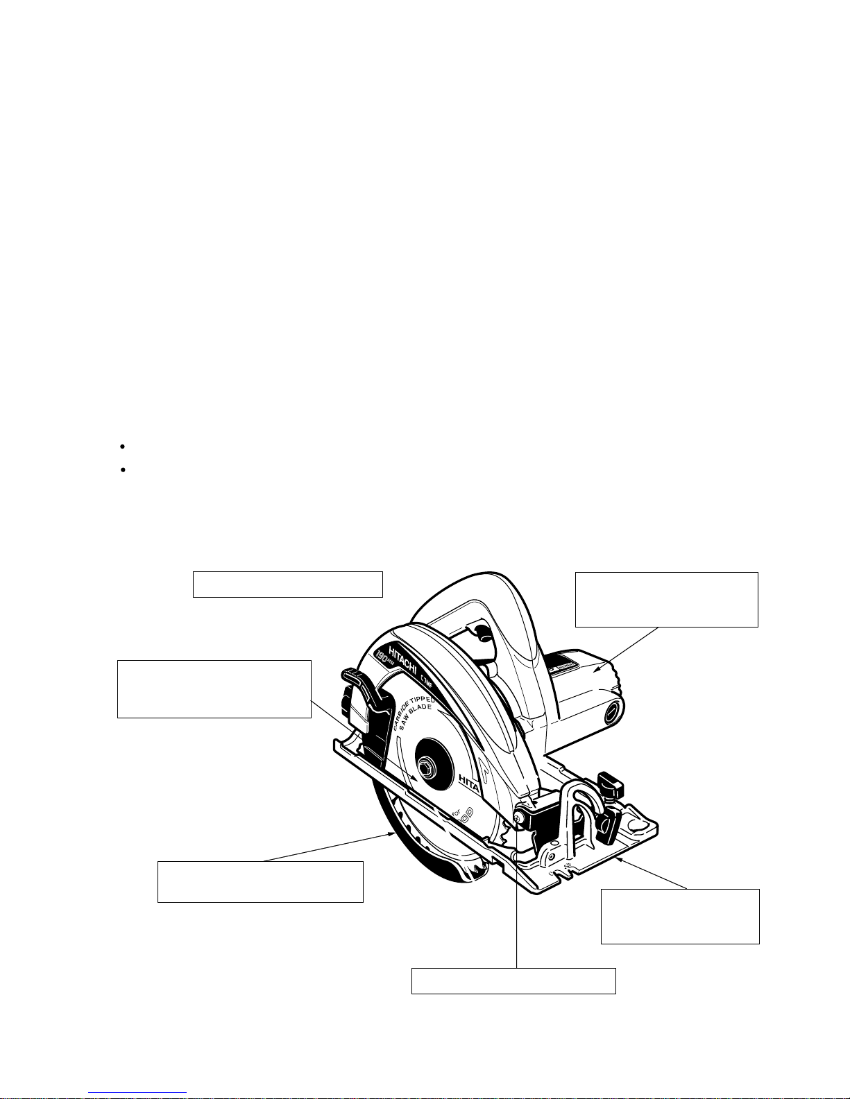
4. SELLING POINTS
Accurate and sturdy
aluminum die-cast base
(Models C 6MF/C 7MF)
Resin protective cover minimizes
scratches on workpieces.
C 7MF
40T TCT saw blade
(C 6SF/C 6MF: 165 mm dia.)
(C 7SF/C 7MF: 190 mm dia.)
Provided wih parallel adjustment
Power-plus heavy-duty motor
(C 6SF: Input 1,010 W)
(C 6MF: Input 1,010 W)
Double-insulated construction
Page 5
--- 2 ---
4-1. Selling Point Descriptions
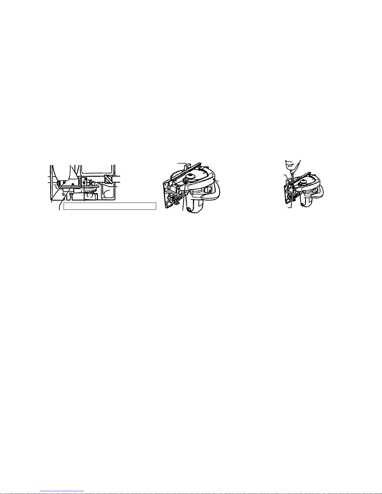
(1) Parallel adjustment system
The parallelism can be easily fine-adjusted by using the parallel adjustment system. The parallelism may be
slightly shifted when the cutting depth is adjusted. If the parallelism is shifted, adjust it according to the
following procedure.
(a) Loosen the locking screw of the saw cover hinge (Fig. 1).
(b) Draw the protective cover in the saw cover.
(c) Hold a piece of wood to the rear of the base and put a mark on the piece of wood at the side of the base
(Fig. 2).
(d) Move the marked piece of wood to the front of the base and turn the parallel adjustment screw until the
mark aligns with the side of the base (Fig. 3).
(e) After adjustment, tighten the locking screw securely.
Fig. 1
(2) Resin protective cover minimizes scratches on workpieces
The lightweight and smooth protective cover is made of resin and minimizes scratching on workpieces.
(3) Power-plus heavy-duty motor (Models C 6SF/C 6MF)
Powerful motor provides greater input and output than those of the Model C 6SE.
(4) Accurate and sturdy aluminum die-cast base (Models C 6MF/C 7MF)
Thanks to the sturdy aluminum die-cast base, the Models C 6MF/C 7MF can cut workpieces accurately and
the cut surfaces of the workpieces are smooth.
(5) High performance 40-tooth tungsten carbide tipped (TCT) saw blade as standard
High performance TCT saw blade (40 teeth) is provided as standard instead of the conventional combination
blade. The Models C 6SF, C 6MF, C 7SF and C 7MF provide greater maximum cutting depth than the
conventional models by using a 165 mm dia. TCT saw blade and a 190 mm dia. TCT saw blade respectively.
(6) Double-insulated construction
Grounding is not required thanks to the double-insulated construction.
Fig. 3Fig. 2
Mark
Saw cover hinge
Saw cover
Sleeve
Locking
screw
Do not loosen the screw of the sleeve.
Protective
cover
Parallel
adjustment
screw
Mark
Page 6
--- 3 ---
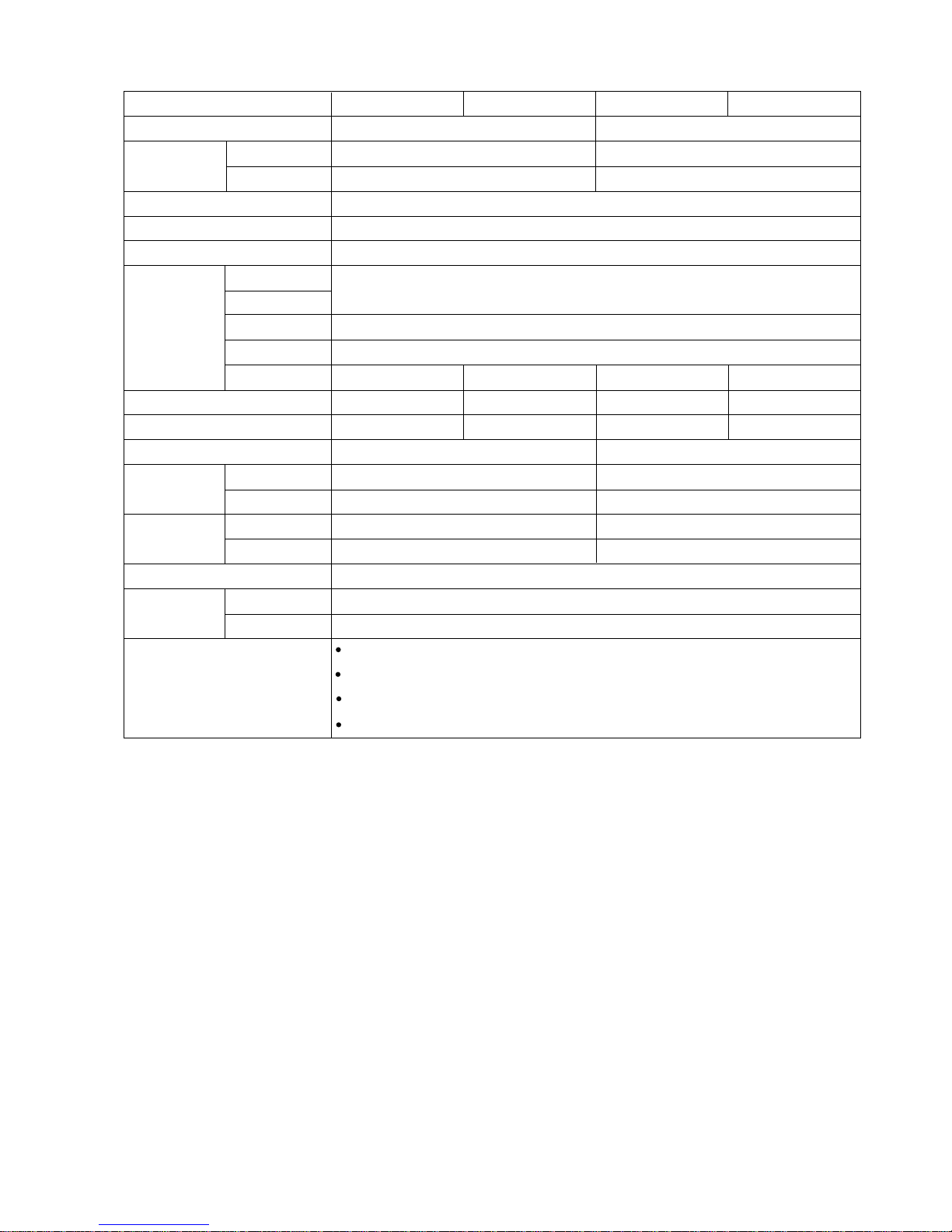
5. SPECIFICATIONS
Model
Saw blade diameter
Cutting depth
at 90˚
at 45˚
Power source
Type of motor
Type of switch
Housing
Handle cover
Enclosure Gear cover
Lower guard
Base
* Voltage (V)
* Current (A)
Power input
Rotation
No-load
speed
Full-load
Weight
Net
Gross
Packaging
Cord
Type
Overall length
Standard equipment
165 mm (6-1/2") 190 mm (7-1/2")
0 --- 57 mm (0 --- 2-1/4") 0 --- 68 mm (0 --- 2-11/16")
Max. 38 mm (1-1/2") Max. 46 mm (1-13/16")
AC single phase 50/60 Hz
AC single phase commutator
Trigger switch
Polycarbonate resin
Cast aluminum
Polycarbonate resin
1,010 W 1,050 W
5,400/min 5,530/min
4,070/min 4,000/min
3.0 kg (6.6 lbs) 3.3 kg (7.3 lbs)
4.3 kg (9.5 lbs) 4.7 kg (10.4 lbs)
Corrugated cardboard box
Two-core cabtire cable
2.5 m (8.2 ft.)
* Check the tool name plate to confirm the rating, as it is subject to change by area.
C 6SF C 7MFC 6MF C 7SF
Sheet metal
220
4.8
Cast aluminum
230
4.8
Cast aluminum
230
4.6
Sheet metal
220
5.0
Tungsten carbide tipped (TCT) saw blade
•••••••••••••••••••••••••••••••••••••••••••••••••
1
Box wrench
•••••••••••••••••••••••••••••••••••••••••••••••••••••••••••••••••••••••••••••••••••••••••••••
1
Parallel guide
••••••••••••••••••••••••••••••••••••••••••••••••••••••••••••••••••••••••••••••••••••••••••
1
Hex. bar wrench
••••••••••••••••••••••••••••••••••••••••••••••••••••••••••••••••••••••••••••••••••••••
1
Page 7

--- 4 ---
HITACHI
C --- 1
HITACHI
C --- 2
C 6SF/C 6MF C 7SF/C 7MF
165 (6-1/2") 160 (6-1/4") 190 (7-1/2") 185 (7-1/4")
57 (2-1/4") 55 (2-5/32") 68 (2-11/16") 66 (2-19/32")
38 (1-1/2") 36 (1-3/8") 46 (1-13/16") 44 (1-23/32")
1,010 950 1,050 1,050
5,000 4,700 5,000 4,700
270/282 268 282/295 282
3.0 (6.6 lbs) 3.3 (7.3 lbs) 3.3 (7.3 lbs) 3.7 (8.2 lbs)
5,400 5,400 5,530 5,130
4,070 3,660 4,000 3,330
550 545 590 700
1,500 1,340 1,500 1,500
84 82 84 84
Provided None Provided None
Steel/Aluminum Steel Steel/Aluminum Steel
Plastic Steel Plastic Steel
Plastic Steel Plastic Steel
270/282 268 282/295 282
229 230 242 240
210 225 210 230
Maker
Model
Saw blade diameter mm
Max. cutting
90˚
depth
45˚
Power input W
No-load rotation speed /min
Overall length mm
Weight kg
No-load rotation speed /min
Full-load rotation speed /min
Full-load output W
Max. output W
No-load noise dB
Palallel adjustment --Material of base --Material of lower guard --Material of wing bolt/nut ---
Lmm
Hmm
Wmm
6. COMPARISONS WITH SIMILAR PRODUCTS
Catalog specifications
Characteristics*
Structure
7. PRECAUTIONS IN SALES PROMOTION
In the interest of promoting the safest and most efficient use of the Models C 6SF, C 6MF, C 7SF and C 7MF
Circular Saws by all of our customers, it is very important that at the time of sale the salesperson carefully
ensures that the buyer seriously recognizes the importance of the contents of the Handling Instructions.
7-1. Handling Instructions
Although every effort is made in each step of design, manufacture, and inspection to provide protection against
safety hazards, the dangers inherent in the use of any electric tool cannot be completely eliminated. Accordingly,
general precautions and suggestions for the use of electric power tools, and specific precautions and suggestions
for the use of the circular saw are listed in the Handling Instructions to enhance the safe and efficient use of the
tool by the customer. Salespersons must be thoroughly familiar with the contents of the Handling Instructions to
be able to offer appropriate guidance to the customer during sales promotion.
* Figures are based on 230 V motors
mm
Page 8
--- 5 ---
8. PRECAUTIONS IN DISASSEMBLY AND REASSEMBLY
The procedures for disassembly and reassembly and certain precautions are described below.
The [Bold] numbers in the descriptions below correspond to the item numbers in the parts list for all the models.
In disassembly or reassembly and also in other work, the Base Ass'y [52] should be carefully handled to prevent
the loss of the accuracy of each part, such as the flatness of the bottom surface.
8-1. Disassembly
Before disassembly, be sure to remove the saw blade to prevent damage to the cutting edge or
injuries by the saw blade.
(1) Removing the Protective Cover [5]
(a) Detach the hook of the Return Spring [6] from the Protective Cover [5].
(b) Loosen the Seal Lock Flat Hd. Screw M3 x 12 [9] securing the Bearing Cover [8], and remove the
Bearing Cover [8] and the Protective Cover [5].
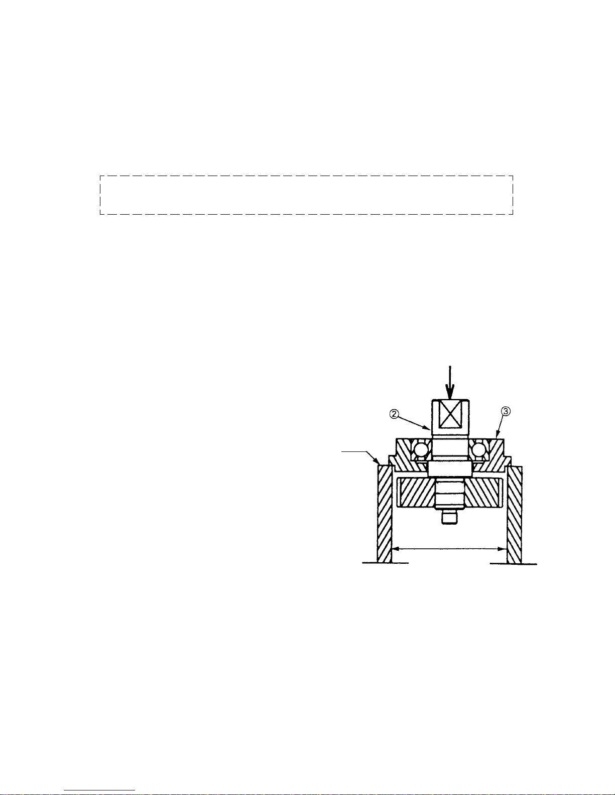
(2) Removing the Bearing Holder [3]
Loosen the Seal Lock Flat Hd. Screw M5 x 12 [4], remove the Bearing Holder [3] together with the Spindle
and Gear Set [2].
Fig. 4
Jig
42 to 43 mm
(3) Removing the Spindle and Gear Set [2] (See Fig. 4.)
Hold the bearing holder in a cylindrical jig with an inside
diameter of 42 mm to 43 mm (approx. 1-23/32"), and
remove it by pushing the end of the spindle.
Important: A gear, once removed, cannot be used again
because it no longer engages. It must be
replaced by a new spindle and gear set.
(4) Removing the Housing Ass'y [17]
(a) Loosen the Brush Caps [34] with a flat-blade
screwdriver and remove the Carbon Brushes [33].
(b) Loosen the Machine Screws (W/Washers) M5 x 45
(Black) [14] securing the Housing Ass'y [17], and
remove the Housing Ass'y [17] and Gear Cover Ass'y
[29].
Push
Page 9

--- 6 ---
(5) Removing the Armature [24] (Fig. 5)
(a) Remove the Lock Lever [25] and tap the end surface of the Housing Ass'y [17] with a wooden hammer.
The Armature [24] and Fan Guide [23] can then be removed.
(b) Remove the Fan Guide [23], Thrust Washer [19] and Bearing Lock [18].
(c) Remove the Ball Bearing 6000VVCMPS2L [26] and Ball Bearing 608VVC2PS2L [20] with a bearing puller.
Fig. 5
Fig. 6
(6) Removing the Stator Ass'y [22] (Fig. 6)
(a) Loosen the two Hex. Hd. Tapping Screws D5 x 55 [40].
(b) Remove the two Brush Terminals [21] from the brush holders of the Housing Ass'y [17].
(c) Lightly tap the end surface of the Housing Ass'y [17] with a wooden hammer to remove the Stator Ass'y
[22].
[17]
[22]
[21]
[18]
[20]
[19]
[23]
[25]
[24]
[26]
[40]
Page 10
--- 7 ---
[28]
[29]
[53]
[52]
[50]
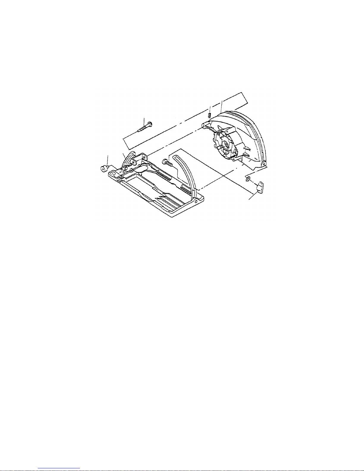
(7) Removing the Base Ass'y [52] (Fig. 7)
(a) Remove the Bolt Ass'y (Square) M6 x 22 [44].
(b) Loosen the two Hex. Socket Set Screw M5 x 6 [28] of the Gear Cover Ass'y [29] and the hex. socket screw
in the Sleeve [50] to remove the Sleeve [50].
(c) Loosen Adjusting Screw (A) [53] and remove it from the Gear Cover Ass'y [29]. Then the Base Ass'y [52]
can be removed.
[44]
Fig. 7
Page 11

--- 8 ---
Fig. 8
8-2. Reassembly
Cautions on installation
Reassembly can be accomplished by following the disassembly procedures reverse. However, particular
attention should be given to the following points:
(1) Assembling the Bearing Lock [18] and Thrust Washer [19] (See Fig. 8.)
Before installing the Armature [24], be sure to install the Bearing Lock [18] and Thrust Washer [19] in the
bearing chamber of the Housing Ass'y [17] in this order. When installing the Thrust Washer [19], be sure to
note its assembling direction.
(2) Assembling the Rubber Ring [27]
When installing the Rubber Ring [27], be careful not to damage the bearing chamber groove of the Gear
Cover Ass'y [29].
Installation order
Steel washer side
Rubber side
[17]
[19]
[18]
Page 12

--- 9 ---
(3) Assembling the Stator Ass'y [22]
As shown in Fig. 9, insert a guide bar [J-132 stator press pins (special repair tool, Code No. 970911) are
recommended] into the Stator Ass'y [22] and the Housing Ass'y [17] to accurately align the screw hole on the
Stator Ass'y [22] with the corresponding hole on the Housing Ass'y [17]. Press-fit the Stator Ass'y [22] into the
Housing Ass'y [17]. Hook the carbon brush terminals in the brush holders. Be careful not to put the internal
wires in the ribs of the Stator Ass'y [22] in the Housing Ass'y [17]. Fix the Stator Ass'y [22] to the Housing
Ass'y [17] with the two Hex. Hd. Tapping Screws D5 x 55 [40].
(4) Assembling the Lock Lever [25] (See Fig. 10.)
(a) Place the notch of the Lock Lever [25] between the fan of the Armature [24] and the ball bearing, and
assemble them into the Gear Cover Ass'y [29]. At this time, both ends of the plate spring of the Lock Lever
[25] should be supported by the inner sides of the ribs (2 places) of the Gear Cover Ass'y [29].
(b) After installation, check the operation of the Lock Lever [25] to particularly ensure that the lever springs
back to its original position when you let go of it.
Fig. 9
Guide bar
(J-132 stator
press pins)
[22]
Name plate side
Brush Holder
[24]
Fig. 10
[29]
[25]
Ribs (2 places)
Page 13

--- 10 ---
(5) Wiring procedure (See Figs. 11 and 12.)
Wiring should be carried out by referring to Figures 11 and 12. During installation, be careful not to pinch the
lead wires between the housing and the handle cover.
Fig. 11
Fig. 12 (Expanded drawing of switch)
(6) Wiring diagram (See Fig. 13.)
Fig. 13
Lead wire from cord
Black
Blue
Blue or white
Brown or black
Lead wire from stator
No connected lead wire
Blue
Lead wire from stator
Brown or black
lead wire from cord
Numbers inside mark indicate numbers of switch terminals.
Blue
Power source
Brown or black
Black
Stator
Armature
Blue or white
Connector
Switch
Page 14

--- 11 ---
(7) Tightening torque values for selected fasteners
• Bolt (W/Washer) M7 x 17.5 [13]
••••••••••••••••••••••••••••••••••••••••••••••
9.8 2.0 N•m (100 20 kgf•cm)
• Seal Lock Flat Hd. Screw M5 x 12 [4]
••••••••••••••••••••••••••••••••••••••
3.4 0.7 N•m (35 7 kgf•cm)
• Seal Lock Flat Hd. Screw M3 x 12 [9]
••••••••••••••••••••••••••••••••••••••
1.8 0.4 N•m (18 4 kgf•cm)
• Machine Screws (W/Washers) M5 x 45 [14]
•••••••••••••••••••••••••••••
3.4 0.7 N•m (35 7 kgf•cm)
• Hex. Hd. Tapping Screws D5 x 55 [40]
••••••••••••••••••••••••••••••••••••
2.9 0.5 N•m (30 5 kgf•cm)
• Tapping Screws (W/Flange) D4 [15] [39]
•••••••••••••••••••••••••••••••••
2.0 0.5 N•m (20 5 kgf•cm)
• Hex. Socket Set Screws M5 x 6 [28]
••••••••••••••••••••••••••••••••••••••••
3.4 0.7 N•m (35 7 kgf•cm)
• Brush Caps [34]
•••••••••••••••••••••••••••••••••••••••••••••••••••••••••••••••••••••
0.7 0.2 N•m (7.5 2.5 kgf•cm)
• Hex. Socket Set Screws M5 x 8 [31]
••••••••••••••••••••••••••••••••••••••••
0.7 0.2 N•m (7.5 2.5 kgf•cm)
• Flat Hd. Screw M6 x 20 [42]
••••••••••••••••••••••••••••••••••••••••••••••••••••
0.7 0.2 N•m (7.5 2.5 kgf•cm)
• Seal lock hex. socket hd. screw M6 for Sleeve [50]
•••••••••••••••••••
3.4 0.7 N•m (35 7 kgf•cm)
• Set screws M3.5 x 7.5 for Switch (1P Pillar Type) W/Lock [46]
•••
0.3 N•m (3 kgf•cm)
+0.07
- 0.05
+0.75
- 0.5
8-3. Insulation Tests
On completion of disassembly and repair, measure the insulation resistance and conduct dielectric strength test.
Insulation resistance: 7 M Ω or more with DC 500 V megohm tester
Dielectric strength: AC 4000 V/1 minute, with no abnormalities
8-4. Deflection of Saw Blade
Allowable deflection level of the saw blade shall be as follows.
8-5. Cleaning the Case
When the unit becomes soiled, clean it with a clean soft rag moistened with soapy water. Since chloric solvents,
gasoline and thinner tend to melt plastic material, their use for cleaning is absolutely avoided.
Model Measuring point Allowable level
C 6SF, C 6MF, C 7SF, C 7MF 150 0.3 mm max.
Page 15

--- 12 ---
9. STANDARD REPAIR TIME (UNIT) SCHEDULES
MODEL 10 20 30 40 50 60 min.
Fixed
Variable
Work Flow
Switch
Handle Cover
Cord
Cord Armor
Protective
Cover
Return Spring
Armature
Ball Bearing
(608VV)
Ball Bearing
(6000VV)
Spindle and
Gear Set
Bearing Holder
Metal
Ball Bearing
(6002VV)
Gear Cover
Ass'y
Housing Ass'y
Stator Ass'y
General Assembly
Base Ass'y
C 6SF
C 7SF
C 6MF
C 7MF
Page 16

ELECTRIC TOOL PARTS LIST
LIST NO. 0597
CIRCULAR SAW
Model C 6SF
2003 • 12 •25
(E1)
Hitachi Power Tools
501
503
502
1
2
3
4
5
6
7
8
9
10
11
12
14
32
33
34
46
47
48
49
50
51
43
52
53
36
38
39
40
41
42
43
44
37
15
16
18
19
20
21
22
23
24
25
26
27
28
29
30
31
17
13
A
A
B
B
45
35
Page 17

*
ALTERNATIVE PARTS
--- 2 ---
ITEM
NO.
CODE NO.
DESCRIPTION REMARKS
NO.
USED
PARTS
12 -- 03
C 6SF
1 963-803 METAL 1
2 322-088 SPINDLE AND GEAR SET 1
3 308-361 BEARING HOLDER 1
4 305-568 SEAL LOCK FLAT HD. SCREW M5X12 2
5 322-506 PROTECTIVE COVER 1
6 317-203 RETURN SPRING 1
7 600-2VV BALL BEARING 6002VVCMPS2L 1
8 308-362 BEARING COVER 1
9 308-773 SEAL LOCK FLAT HD. SCREW M3X12 3
10 322-099 WASHER (A) 1
11 TCT SAW BLADE 165MM-D20 HOLE-NT40 1
12 322-100 WASHER (B) 1
13 957-749 BOLT (W/WASHER) M7X17.5 1
14 302-434
MACHINE SCREW (W/WASHERS) M5X45 (BLACK)
3
15 301-653
TAPPING SCREW (W/FLANGE) D4X20 (BLACK) 3
16 NAME PLATE 1
17 322-504 HOUSING ASS’Y 1 INCLUD. 31, 32
18 931-701 BEARING LOCK 1
19 316-394 THRUST WASHER 1
20 608-VVM BALL BEARING 608VVC2PS2L 1
21 930-703 BRUSH TERMINAL 2
22 340-571E STATOR ASS’Y 220V-230V 1 INCLUD. 21
23 322-002 FAN GUIDE 1
24 360-624E ARMATURE 220V-230V 1
25 307-918 LOCK LEVER 1
26 600-0VV BALL BEARING 6000VVCMPS2L 1
27 957-754 RUBBER RING 1
28 962-782 HEX. SOCKET SET SCREW M5X6 1
29 322-004 GEAR COVER ASS’Y 1 INCLUD. 27, 41, 42
30 HITACHI LABEL 1
31 938-477 HEX. SOCKET SET SCREW M5X8 2
32 957-051 BRUSH HOLDER 2
33 999-043 CARBON BRUSH (1 PAIR) 2
34 935-829 BRUSH CAP 2
35 981-373 TUBE (D) 1
36 953-327 CORD ARMOR D8.8 1
37 959-140 CONNECTOR 50091 (10 PCS.) 1
38 937-631 CORD CLIP 1
39 984-750 TAPPING SCREW (W/FLANGE) D4X16 2
40 953-174 HEX. HD. TAPPING SCREW D5X55 2
41 961-729 CUSHION 1
42 949-794 FLAT HD. SCREW M6X20 (10 PCS.) 1
43 948-167 SUPER LOCK WASHER M6 2
44 314-620 BOLT ASS’Y (SQUARE) M6X22 1 INCLUD. 43
* 45 500-468Z CORD 1 (CORD ARMOR D8.8)
* 45 500-234Z CORD 1 (CORD ARMOR D8.8) FOR INA
* 45 500-423Z CORD 1 (CORD ARMOR D8.8) FOR SIN, MAL
* 45 500-435Z CORD 1 (CORD ARMOR D8.8) FOR HKG
46 322-578 SWITCH (1P PILLAR TYPE) W/LOCK 1
47 322-505 HANDLE COVER 1
48 941-056 SPRING 1
Page 18

*
ALTERNATIVE PARTS --- 3 ---
ITEM
NO.
CODE NO.
DESCRIPTION REMARKS
NO.
USED
PARTS
12 -- 03
C 6SF
49 307-898 WING BOLT M6X18 1
50 315-253 SLEEVE 1
51 308-364 WING BOLT (A) M6X15 1
52 322-007 BASE ASS’Y 1 INCLUD. 43, 48, 49, 51
53 315-183 ADJUSTING SCREW (A) 1
Page 19

*
ALTERNATIVE PARTS
--- 4 ---
OPTIONAL ACCESSORIES
ITEM
NO.
CODE NO.
DESCRIPTION
REMARKS
NO.
USED
12 -- 03
STANDARD ACCESSORIES
ITEM
NO.
CODE NO.
DESCRIPTION
REMARKS
NO.
USED
C 6SF
Printed in Japan
(031225N)
501 302-756 GUIDE 1
502 990-666 HEX. BAR WRENCH 2.5MM 1
503 940-543 BOX WRENCH 10MM 1
601 954-619 CORD HANGER 1
Page 20

ELECTRIC TOOL PARTS LIST
LIST NO. 0599
CIRCULAR SAW
Model C 6MF
2003 • 12 •25
(E1)
Hitachi Power Tools
501
503
502
1
2
3
4
5
6
7
8
9
10
11
12
14
32
33
34
46
47
48
49
50
51
52
53
43
36
38
39
40
41
42
43
44
37
15
16
18
19
20
21
22
23
24
25
26
27
28
30
31
17
13
A
A
B
B
45
35
29
Page 21

*
ALTERNATIVE PARTS
--- 2 ---
ITEM
NO.
CODE NO.
DESCRIPTION REMARKS
NO.
USED
PARTS
12 -- 03
C 6MF
1 963-803 METAL 1
2 322-088 SPINDLE AND GEAR SET 1
3 308-361 BEARING HOLDER 1
4 305-568 SEAL LOCK FLAT HD. SCREW M5X12 2
5 322-506 PROTECTIVE COVER 1
6 317-203 RETURN SPRING 1
7 600-2VV BALL BEARING 6002VVCMPS2L 1
8 308-362 BEARING COVER 1
9 308-773 SEAL LOCK FLAT HD. SCREW M3X12 3
10 322-099 WASHER (A) 1
11 TCT SAW BLADE 165MM-D20 HOLE-NT40 1
12 322-100 WASHER (B) 1
13 957-749 BOLT (W/WASHER) M7X17.5 1
14 302-434
MACHINE SCREW (W/WASHERS) M5X45 (BLACK)
3
15 301-653
TAPPING SCREW (W/FLANGE) D4X20 (BLACK)
3
16 NAME PLATE 1
17 322-504 HOUSING ASS’Y 1 INCLUD. 31, 32
18 931-701 BEARING LOCK 1
19 316-394 THRUST WASHER 1
20 608-VVM BALL BEARING 608VVC2PS2L 1
21 930-703 BRUSH TERMINAL 2
22 340-571E ST ATOR ASS’Y 220V-230V 1 INCLUD. 21
23 322-002 FAN GUIDE 1
24 360-624E ARMATURE 220V-230V 1
25 307-918 LOCK LEVER 1
26 600-0VV BALL BEARING 6000VVCMPS2L 1
27 957-754 RUBBER RING 1
28 962-782 HEX. SOCKET SET SCREW M5X6 1
29 322-004 GEAR COVER ASS’Y 1 INCLUD. 27, 41, 42
30 HITACHI LABEL 1
31 938-477 HEX. SOCKET SET SCREW M5X8 2
32 957-051 BRUSH HOLDER 2
33 999-043 CARBON BRUSH (1 PAIR) 2
34 935-829 BRUSH CAP 2
35 981-373 TUBE (D) 1
36 953-327 CORD ARMOR D8.8 1
37 959-140 CONNECTOR 50091 (10 PCS.) 1
38 937-631 CORD CLIP 1
39 984-750 TAPPING SCREW (W/FLANGE) D4X16 2
40 953-174 HEX. HD. TAPPING SCREW D5X55 2
41 961-729 CUSHION 1
42 949-794 FLAT HD. SCREW M6X20 (10 PCS.) 1
43 948-167 SUPER LOCK WASHER M6 2
44 314-620 BOLT ASS’Y (SQUARE) M6X22 1 INCLUD. 43
* 45 500-468Z CORD 1 (CORD ARMOR D8.8)
* 45 500-234Z CORD 1 (CORD ARMOR D8.8) FOR INA
* 45 500-423Z CORD 1 (CORD ARMOR D8.8) FOR SIN, MAL
* 45 500-435Z CORD 1 (CORD ARMOR D8.8) FOR HKG
46 322-578 SWITCH (1P PILLAR TYPE) W/LOCK 1
47 322-505 HANDLE COVER 1
48 941-056 SPRING 1
Page 22

*
ALTERNATIVE PARTS --- 3 ---
ITEM
NO.
CODE NO.
DESCRIPTION REMARKS
NO.
USED
PARTS
12 -- 03
C 6MF
49 307-898 WING BOLT M6X18 1
50 315-253 SLEEVE 1
51 307-937 WING BOLT (A) 1
52 322-021 BASE ASS’Y 1 INCLUD. 43, 48, 49, 51
53 315-183 ADJUSTING SCREW (A) 1
Page 23

*
ALTERNATIVE PARTS
--- 4 ---
OPTIONAL ACCESSORIES
ITEM
NO.
CODE NO.
DESCRIPTION
REMARKS
NO.
USED
12 -- 03
STANDARD ACCESSORIES
ITEM
NO.
CODE NO.
DESCRIPTION
REMARKS
NO.
USED
C 6MF
Printed in Japan
(031225N)
501 302-756 GUIDE 1
502 990-666 HEX. BAR WRENCH 2.5MM 1
503 940-543 BOX WRENCH 10MM 1
601 954-619 CORD HANGER 1
Page 24

ELECTRIC TOOL PARTS LIST
LIST NO. 0598
CIRCULAR SAW
Model C 7SF
2003 • 12 •25
(E1)
Hitachi Power Tools
501
503
502
1
2
3
4
5
6
7
8
9
10
11
12
14
32
45
33
34
35
46
47
48
49
50
51
52
53
43
36
39
40
41
42
43
44
37
38
15
16
18
19
20
21
22
23
24
25
26
27
28
29
30
17
13
A
A
B
B
31
Page 25

*
ALTERNATIVE PARTS
--- 2 ---
ITEM
NO.
CODE NO.
DESCRIPTION REMARKS
NO.
USED
PARTS
12 -- 03
C 7SF
1 963-803 METAL 1
2 322-088 SPINDLE AND GEAR SET 1
3 308-361 BEARING HOLDER 1
4 305-568 SEAL LOCK FLAT HD. SCREW M5X12 2
5 322-507 PROTECTIVE COVER 1
6 317-203 RETURN SPRING 1
7 600-2VV BALL BEARING 6002VVCMPS2L 1
8 308-362 BEARING COVER 1
9 308-773 SEAL LOCK FLAT HD. SCREW M3X12 3
10 322-099 WASHER (A) 1
11 TCT SAW BLADE 190MM-D20 HOLE-NT40 1
12 322-100 WASHER (B) 1
13 957-749 BOLT (W/WASHER) M7X17.5 1
14 302-434
MACHINE SCREW (W/WASHERS) M5X45 (BLACK)
3
15 301-653
TAPPING SCREW (W/FLANGE) D4X20 (BLACK)
3
16 NAME PLATE 1
17 322-504 HOUSING ASS’Y 1 INCLUD. 31, 32
18 931-701 BEARING LOCK 1
19 316-394 THRUST WASHER 1
20 608-VVM BALL BEARING 608VVC2PS2L 1
21 930-703 BRUSH TERMINAL 2
22 340-571E ST ATOR ASS’Y 220V-230V 1 INCLUD. 21
23 322-002 FAN GUIDE 1
24 360-624E ARMATURE 220V-230V 1
25 307-918 LOCK LEVER 1
26 600-0VV BALL BEARING 6000VVCMPS2L 1
27 957-754 RUBBER RING 1
28 962-782 HEX. SOCKET SET SCREW M5X6 1
29 322-015 GEAR COVER ASS’Y 1 INCLUD. 27, 41, 42
30 HITACHI LABEL 1
31 938-477 HEX. SOCKET SET SCREW M5X8 2
32 957-051 BRUSH HOLDER 2
33 999-043 CARBON BRUSH (1 PAIR) 2
34 935-829 BRUSH CAP 2
35 981-373 TUBE (D) 1
36 953-327 CORD ARMOR D8.8 1
37 959-140 CONNECTOR 50091 (10 PCS.) 1
38 937-631 CORD CLIP 1
39 984-750 TAPPING SCREW (W/FLANGE) D4X16 2
40 953-174 HEX. HD. TAPPING SCREW D5X55 2
41 961-729 CUSHION 1
42 949-794 FLAT HD. SCREW M6X20 (10 PCS.) 1
43 948-167 SUPER LOCK WASHER M6 2
44 314-620 BOLT ASS’Y (SQUARE) M6X22 1 INCLUD. 43
* 45 500-468Z CORD 1 (CORD ARMOR D8.8)
* 45 500-234Z CORD 1 (CORD ARMOR D8.8) FOR INA
* 45 500-423Z CORD 1 (CORD ARMOR D8.8) FOR SIN, MAL
* 45 500-435Z CORD 1 (CORD ARMOR D8.8) FOR HKG
46 322-578 SWITCH (1P PILLAR TYPE) W/LOCK 1
47 322-505 HANDLE COVER 1
48 941-056 SPRING 1
Page 26

*
ALTERNATIVE PARTS --- 3 ---
ITEM
NO.
CODE NO.
DESCRIPTION REMARKS
NO.
USED
PARTS
12 -- 03
C 7SF
49 307-898 WING BOLT M6X18 1
50 315-253 SLEEVE 1
51 308-364 WING BOLT (A) M6X15 1
52 322-016 BASE ASS’Y 1 INCLUD. 43, 48, 49, 51
53 315-183 ADJUSTING SCREW (A) 1
Page 27

*
ALTERNATIVE PARTS
--- 4 ---
OPTIONAL ACCESSORIES
ITEM
NO.
CODE NO.
DESCRIPTION
REMARKS
NO.
USED
12 -- 03
STANDARD ACCESSORIES
ITEM
NO.
CODE NO.
DESCRIPTION
REMARKS
NO.
USED
C 7SF
Printed in Japan
(031225N)
501 302-756 GUIDE 1
502 990-666 HEX. BAR WRENCH 2.5MM 1
503 940-543 BOX WRENCH 10MM 1
601 954-619 CORD HANGER 1
Page 28

ELECTRIC TOOL PARTS LIST
LIST NO. E501
CIRCULAR SAW
Model C 7MF
2003 • 12 •25
(E1)
Hitachi Power Tools
501
503
502
1
2
3
4
5
6
7
8
9
10
11
12
14
32
33
34
46
47
48
49
50
51
52
53
43
36
39
40
41
42
43
44
37
38
15
16
18
19
20
21
22
23
24
25
26
27
28
29
30
17
13
A
B
B
45
35
31
A
Page 29

*
ALTERNATIVE PARTS
--- 2 ---
ITEM
NO.
CODE NO.
DESCRIPTION REMARKS
NO.
USED
PARTS
12 -- 03
C 7MF
1 963-803 METAL 1
2 322-088 SPINDLE AND GEAR SET 1
3 308-361 BEARING HOLDER 1
4 305-568 SEAL LOCK FLAT HD. SCREW M5X12 2
5 322-507 PROTECTIVE COVER 1
6 317-203 RETURN SPRING 1
7 600-2VV BALL BEARING 6002VVCMPS2L 1
8 308-362 BEARING COVER 1
9 308-773 SEAL LOCK FLAT HD. SCREW M3X12 3
10 322-099 WASHER (A) 1
11 TCT SAW BLADE 190MM-D20 HOLE-NT40 1
12 322-100 WASHER (B) 1
13 957-749 BOLT (W/WASHER) M7X17.5 1
14 302-434
MACHINE SCREW (W/WASHERS) M5X45 (BLACK)
3
15 301-653
TAPPING SCREW (W/FLANGE) D4X20 (BLACK)
3
16 NAME PLATE 1
17 322-504 HOUSING ASS’Y 1 INCLUD. 31, 32
18 931-701 BEARING LOCK 1
19 316-394 THRUST WASHER 1
20 608-VVM BALL BEARING 608VVC2PS2L 1
21 930-703 BRUSH TERMINAL 2
22 340-571E STAT OR ASS’Y 220V-230V 1 INCLUD. 21
23 322-002 FAN GUIDE 1
24 360-624E ARMATURE 220V-230V 1
25 307-918 LOCK LEVER 1
26 600-0VV BALL BEARING 6000VVCMPS2L 1
27 957-754 RUBBER RING 1
28 962-782 HEX. SOCKET SET SCREW M5X6 1
29 322-015 GEAR COVER ASS’Y 1 INCLUD. 27, 41, 42
30 HITACHI LABEL 1
31 938-477 HEX. SOCKET SET SCREW M5X8 2
32 957-051 BRUSH HOLDER 2
33 999-043 CARBON BRUSH (1 PAIR) 2
34 935-829 BRUSH CAP 2
35 981-373 TUBE (D) 1
36 953-327 CORD ARMOR D8.8 1
37 959-140 CONNECTOR 50091 (10 PCS.) 1
38 937-631 CORD CLIP 1
39 984-750 TAPPING SCREW (W/FLANGE) D4X16 2
40 953-174 HEX. HD. TAPPING SCREW D5X55 2
41 961-729 CUSHION 1
42 949-794 FLAT HD. SCREW M6X20 (10 PCS.) 1
43 948-167 SUPER LOCK WASHER M6 2
44 314-620 BOLT ASS’Y (SQUARE) M6X22 1 INCLUD. 43
* 45 500-468Z CORD 1 (CORD ARMOR D8.8)
* 45 500-234Z CORD 1 (CORD ARMOR D8.8) FOR INA
* 45 500-423Z CORD 1 (CORD ARMOR D8.8) FOR SIN, MAL
* 45 500-435Z CORD 1 (CORD ARMOR D8.8) FOR HKG
46 322-578 SWITCH (1P PILLAR TYPE) W/LOCK 1
47 322-505 HANDLE COVER 1
48 941-056 SPRING 1
Page 30

*
ALTERNATIVE PARTS --- 3 ---
ITEM
NO.
CODE NO.
DESCRIPTION REMARKS
NO.
USED
PARTS
12 -- 03
C 7MF
49 307-898 WING BOLT M6X18 1
50 315-253 SLEEVE 1
51 307-937 WING BOLT (A) 1
52 322-022 BASE ASS’Y 1 INCLUD. 43, 48, 49, 51
53 315-183 ADJUSTING SCREW (A) 1
Page 31

*
ALTERNATIVE PARTS
--- 4 ---
OPTIONAL ACCESSORIES
ITEM
NO.
CODE NO.
DESCRIPTION
REMARKS
NO.
USED
12 -- 03
STANDARD ACCESSORIES
ITEM
NO.
CODE NO.
DESCRIPTION
REMARKS
NO.
USED
C 7MF
Printed in Japan
(031225N)
501 302-756 GUIDE 1
502 990-666 HEX. BAR WRENCH 2.5MM 1
503 940-543 BOX WRENCH 10MM 1
601 954-619 CORD HANGER 1
Page 32

 Loading...