

Page 1

C28W433N
C32W433N
User Guide
Page 2

Dear Hitachi Customer,
Congratulations on your purchase of the very latest state of the art television from HITACHI. At Hitachi
we pride ourselves on producing high quality televisions with
outstanding picture and audio capabilities, coupled with Hitachi s reputation for superior reliability.
You should enjoy many years of trouble free operation from your TV. Take some time to read the Operating Guide thoroughly,
and if you encounter any difficulty, firstly refer to the T rouble Shooting guide at the rear of this manual. If, in the unlikely event
of a problem occurring on your TV, contact your dealer immediately. Please read the Guarantee carefully.
*Dolby Pro Logic Surround Sound is the domestic version of Cinema Dolby stereo sound, and allows the viewer
to enjoy full cinematic sound quality when watching films or events recorded in Dolby Surround. The surround
channels reinforce the stereo image, allowing front to rear sound movements (such as overhead aircraft effects)
which immerses the viewer in ambience and special effects. In addition to this, the Pro Logic circuitry is able to
create a centre channel, this anchors dialogue and central sounds to the screen so that speech does not
become disembodied or lost in sound effects.
Dolby Pro Logic together with Hitachi s unique 3DS Spatial Sound system will allow you to enjoy full
Cinema Sound in your own home. In addition to this your Hitachi TV has full expansion sockets to accommodate
optional speaker systems, so you can set up your listening area to match your most exacting audio demands
and aesthetic preferences. These features along with outstanding picture quality and of course our reputation
for superior reliability will continually reward your decision for choosing HITACHI.
*Manufactured under license from Dolby Laboratories Licensing Corporation. DOLBY, the double-D Symbol
and PRO LOGIC are the trademarks of Dolby Laboratories Licensing Corporation.
TV Introduction
TV Introduction
CONTENTS
Introduction & Contents 2
TV Safety 3
Battery Installation & Safety 4
TV Installation 5
General TV Controls Overview 6
Automatic Tuning Procedure 7
Manual Tuning Procedure 9
Picture & Audio Controls 12
HITACHI 3DS System 14
Speaker Configuration Menu 15
Sound Mode 16
Surround Setup Menu 17
Connecting External Audio Equipment 18
Feature Menu 19
W idescreen Modes 20
Connecting External AV equipment 22
Handset Controls 24
Handset Functions 25
Teletext & VCR Operation 26
Trouble Shooting Guide 27
Your Guarantee 28
Technical Specifications 29
Environmental Notice from HITACHI 30
2
2
Page 3

TV Safety
TV Safety
3
3
This television has been designed and manufactured to meet international safety standards, but like any
electrical equipment, care must be taken if you are to obtain the best results and safety is to be assured.
D O N O T cut of f the fitted mains plug as it may contain a special radio interference filter, the removal of which could lead to
impaired performance. If you wish to extend the lead, obtain an appropriate extension lead or consult your dealer.
D O N O T continue to operate the equipment if you are in any doubt about it working normally or if it is damaged in any way switch off, withdraw the mains plug and consult your dealer.
IF you intend placing this TV into a cabinet or a wall alcove, please ensure there is at least a 100mm (10cm) gap to the sides,
rear and top of the TV. This is to allow for adequate ventilation during your TV’s operation.
D O N O T leave equipment switched on when it is unattended unless it is specifically stated that it is designed for unattended
operation or has a stand-by mode. Switch off using the switch on the equipment and show your family how to do this. Make
special arrangements for infirm or handicapped people.
D O N O T obstruct the ventilation of the equipment, for example with curtains or soft furnishings. Overheating will cause damage
and shorten the lifespan of your equipment.
D O N O T use makeshift stands and NEVER fix legs with wood screws - to ensure complete safety, always fit the manufacturers
approved stand or legs with the fixings provided according to the instructions.
D O N O T allow electrical equipment to be exposed to rain or moisture.
NEVER let anyone, especially children, push anything into holes, slots, or any other opening in the case this could result in a fatal electrical shock. Under NO circumstances remove the rear cover of your TV!
NEVER guess or take chances with electrical equipment of any kind - it is better to be safe than sorry!
D O be careful with any glass panels or doors on equipment.
D O consult your dealer if you are in any doubt about installation, operation or safety of your equipment.
D O place your TV on a flat surface, or if supplied, the stand accessory.
D O N O T remove any fixed cover as this may expose dangerous voltages.
D O ensure that all connections, (including the mains plug, extension leads and inter-connections between the pieces of
equipment), are properly made and in accordance with the manufacturers instructions. Switch off and withdraw the mains plug
before making or changing connections.
D O N O T listen to headphones at high volume, as such use can permanently damage your hearing.
D O read the operating instructions before you attempt to use the equipment.
D O N O T use equipment such as personal stereos or radios so that you are distracted from the requirements of traf fic safety. It
is illegal to watch television whilst driving.
D O N O T place hot objects such as candles or nightlights on, or close to, equipment. High temperatures can melt plastic and
lead to fires.
D O observe the manufacturers instructions when connecting extension leads to your TV. The fuse should be a 5 Amp fuse with the
safety symbols and displayed. If you are in any doubt about the extension installation, please consult a competent
electrician.
D O N O T place objects filled with liquids, e.g. a vase, on, or close to the equipment, to avoid spillages into the inside of the
apparatus.
SHOULD you require to replace the fuse in the moulded plug with a new fuse, then please replace with one of the same value,
type and approval as the original. Ensure the fuse cover is returned to its original position.
TO prevent scratching or damaging the tube face, do not knock or rub the surface with sharp or hard objects. Clean the screen
with a soft cloth moistened with warm water and dry with a soft cloth. A mild soap may be used if the screen is extremely dirty.
Do not use harsh or abrasive cleaners!
Page 4
Battery Installation
Battery Installation
Battery Safety Guidelines
Battery Safety Guidelines
Used correctly, batteries are a safe and dependable source of portable power. However, problems can occur if they are misused
or abused - resulting in leakage, or in extreme cases, fire or explosion. Here are some simple guidelines to safe battery use
designed to eliminate any such problems.
4
4
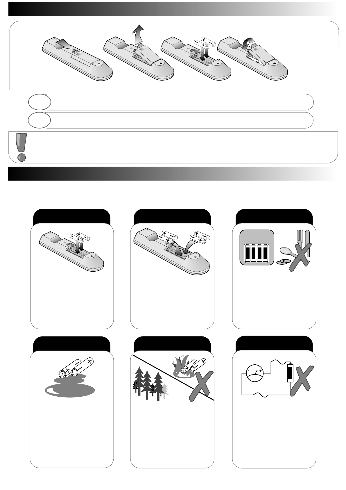
always
Take care to fit your batteries
correctly, observing the plus +
and minus - marks on the battery
and appliance. Incorrect fitting can
cause leakage, or in extreme
cases, fire or explosion.
always
Replace the whole set of batteries
at one time, taking care not to mix
old and new batteries of different
types, since this can result in
leakage, or in extreme cases, fire
or explosion.
always
Store unused batteries in their
packaging and away from metal
objects which may cause a short
circuit resulting in leakage, or in
extreme cases, fire or explosion.
+-+-+-+
-
always
Remove dead batteries from
equipment, and all batteries from
equipment that is to be left for long
periods of time without any use.
Otherwise the batteries may leak
and cause damage.
never!
Never dispose of batteries in fire
as this can cause an explosion.
Respect the environment - always
dispose of batteries in an
environmentally friendly manner.
never!
Never attempt to recharge ordinary
batteries, either in a charger or by
applying heat to them. They may leak,
cause fire or even explode.
Rechargeable NiCAD batteries and
chargers can be purchased from any
good High Street electrical retailer.
CHARGE
+
-
1. When inserting the batteries make sure the polarities are correct, that is, + to + , - to - .
2. Replace the batteries with the equivalent AA t ype.
3. Discard old batteries safely, following the battery safety guidelines.
1
2
Remove cover of handset by lifting up the cover at the recess.
Insert batteries into handset as shown and replace cover.
Page 5
2 x 12W 8
L
R
Before installing your TV please read the following important notes:
If you intend placing this TV into a cabinet or a wall alcove, please ensure there is at least a 100mm (10cm) gap to the sides, rear and top of the
Television. This is to allow for adequate ventilation during TV operation.
Don t allow soft furnishings such as curtains to be draped over the TV whilst in operation.
Never place the TV on to a carpet during normal operation - this could obstruct ventilation slots on the base of the TV. Always place the TV on a flat
surface , or if supplied, the stand accessory.
Failure to observe the above guidelines could result in serious overheating of your TV
, or in extreme cases, even fire.
TV Installation
TV Installation
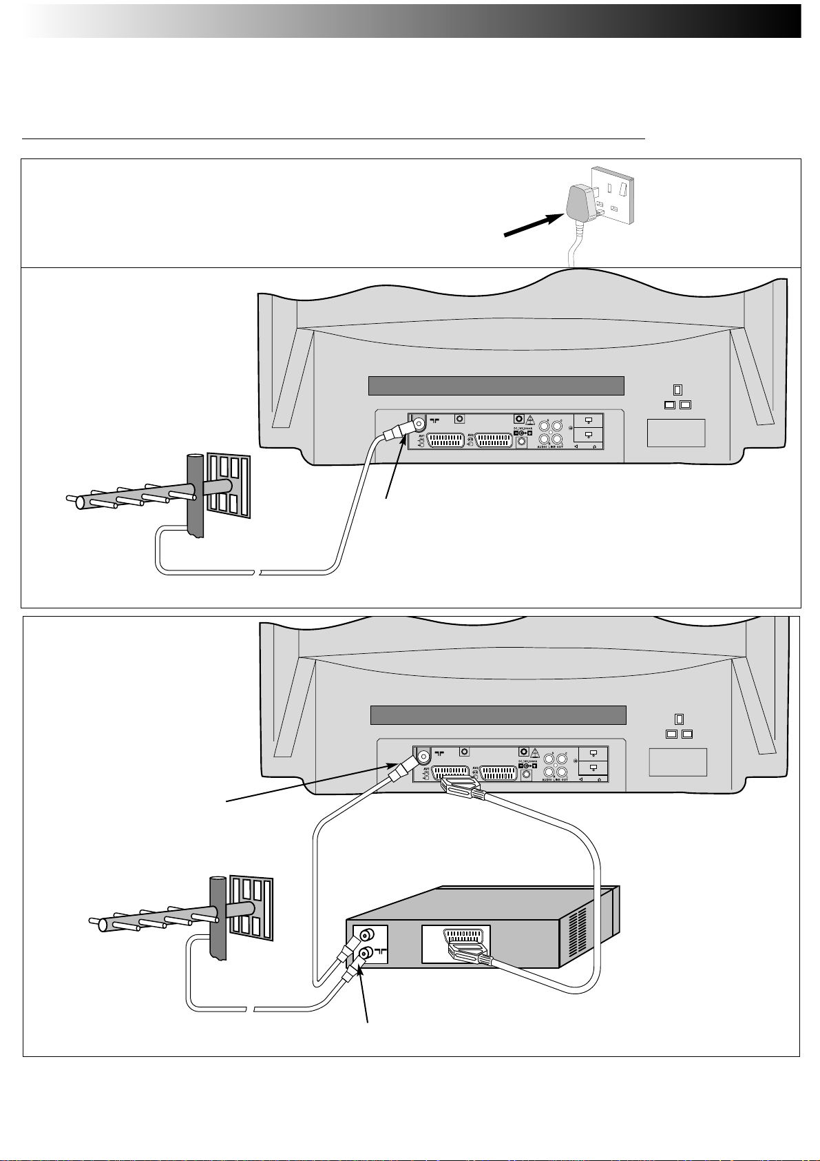
TV only installation.
Installation via a VCR.
Aerial (RF) Lead
Aerial (RF) Socket
*A scart lead should be fitted between your TV and VCR to enhance your picture and sound quality. Scart leads are essential if you have a
stereo TV and VCR and wish to obtain stereo sound from your equipment. These leads can be purchased from your Hitachi dealer or any
good High Street electrical retailer.
Connecting your TV to the mains socket.
(Please read the Safety Notes in the TV Safety Section
with reference to unattended operation).
Insert Plug and
Switch on
5
5
OUT
2 x 12W 8
L
R
*Optional Scart Lead:
TV to VCR
Aerial (RF) Socket TV
(RF) connecter lead VCR to TV
Aerial (RF) Lead
Aerial (RF) Socket VCR
Page 6
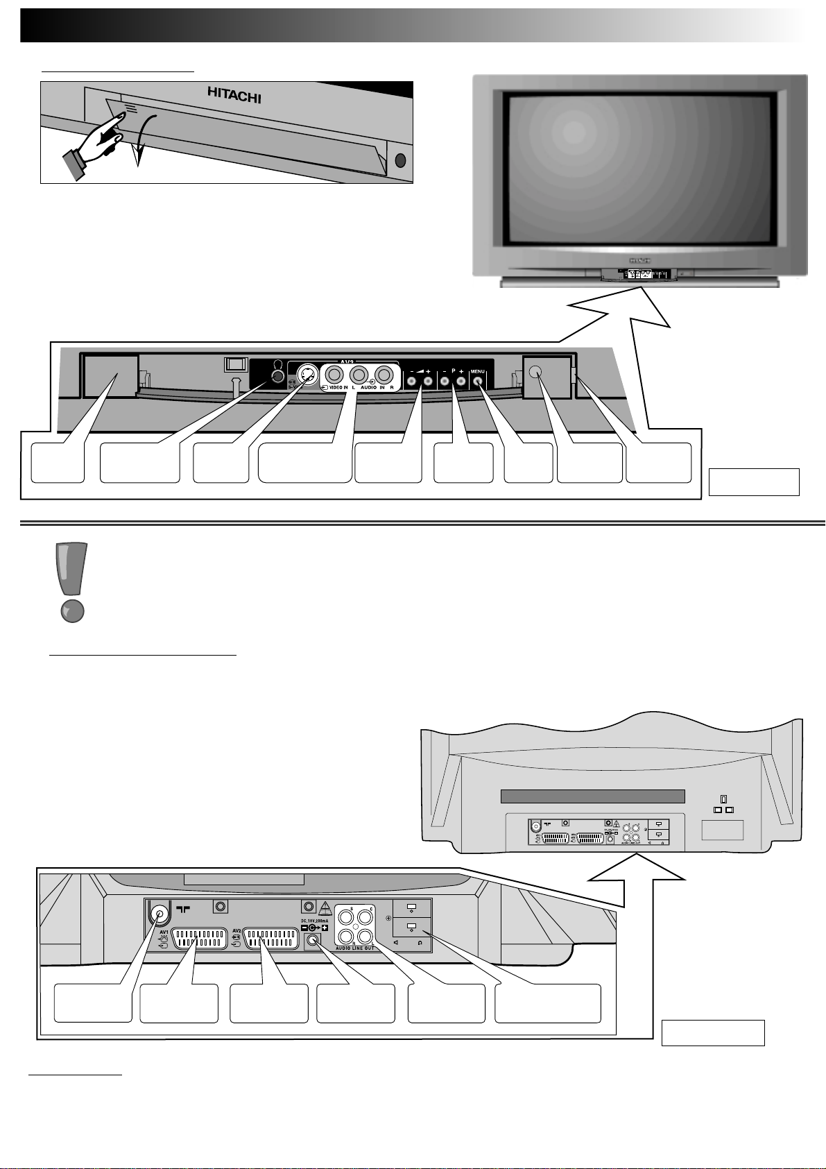
On/off
Switch
Headphone
Socket
S-VHS
Socket
Audio/Video
Input Sockets
Volume+/-
Buttons
InfraRed
lens
TV Mode
Light
P+/P-
Buttons
MENU
Button
FRONT CONTROL PANEL
Access to the front control panel is gained by pushing the door in
and releasing. The front control panel contains items such as the
Headphone socket, Audio/Video sockets, Programme + /- and
V olume +/- buttons. Also located on the front are the ON/OFF
button, Infra Red Lens and TV Mode Light.
TV Controls Overview
TV Controls Overview
REAR CONNECTING SOCKETS
The rear of your TV contains an aerial RF input and two scart
sockets, AV1 and AV2. The RF/ aerial socket is
permanently connected to an RF source i.e. an aerial antenna
shown in TV Installation section . The scart sockets are used to
connect external equipment such as VCR s, Satellite Receivers /
Decoder etc. Connection of this equipment is explained in greater
detail in the Connecting of External AV Equipment section of
this manual. Also located on the rear of the TV are the Audio
Sockets and the *18 Volt Output socket.
Consult your HITACHI dealer with regards to purchasing
HITACHI auxiliary equipment.
RF Aerial
Input Socket
Scart Socket
AV1
Scart Socket
AV2
*18V Output
Socket
Audio Output
Sockets
External Speaker
Sockets
2 x 12W 8
L
R
SWITCHING ON
To switch your TV on, press the ON/OFF button shown above. If the TV fails to display anything on the screen, but the red TV mode light
appears bright, then the TV is in Stand by mode. Press the Stand by button on your handset to
activate the TV. The red TV mode light will then dim and you should allow the TV a few seconds for a picture to appear.
6
6
* IF FITTED
**
*IMPORTANT NOTE The 18 Volt Output socket is used for connection of HITACHI
auxiliary equipment only and under no circumstances should be connected to other
external equipment. Failure to observe this may result in serious damage to your equipment.
*
** IF FITTED
L
R
2 x 12W 8
Page 7

If language setting is incorrect, use up/down
buttons to highlight LANGUAGE, and select
using the left/right buttons.
Automatic T
Automatic T
uning Procedure
uning Procedure
7
7
Completed Autotune example.
SIGNAL QUALITY - If poor or noisy signals are experienced from your TV during normal operation, fit the supplied
Relay RF cable between your VCR and TV. This measure will improve the picture quality on your TV.
To automatically tune this TV to your local broadcasting stations follow the step by step guide below. Once the TV has found
all your local stations, then they are automatically assigned into the following order:
1.BBC1; 2: BBC2; 3: ITV; 4:CH4/S4C; 5: CH5 (subject to availability); 6: Satellite.
Alternatively, if you are familiar with local broadcasting frequency or CH numbers, then these can be entered manually. Please
refer to the Manual Tuning Procedure section of this booklet.
IMPORTANTNOTE: If you have a VCR or a Satellite receiver connected to this TV please ensure that they are switched on
before Autotune commences. In the case of a VCR, insert a pre-recorded tape and begin playback of your equipment. Wi th
a Satellite receiver, select SKY NEWS. These measures ensure that all your equipment is tuned in during the AUTOTUNE
procedure. (Satellite equipment installation is explained in the Connecting of External AV Equipment section ).
Note: The VCR programme number should always be set to 0
Highlight INSTALL using the up/down buttons
(if INSTALL is not shown follow step
above once more).
Press the left/right buttons select INSTALL.
The INSTALL menu is shown.
2
3
Use the up/down buttons to highlight
AUTOTUNE.
Use the left/right buttons to begin
AUTOTUNE.
4
5
6
Press and HOLD the MENU button until Main
Menu with INSTALL is shown
1
Page 8
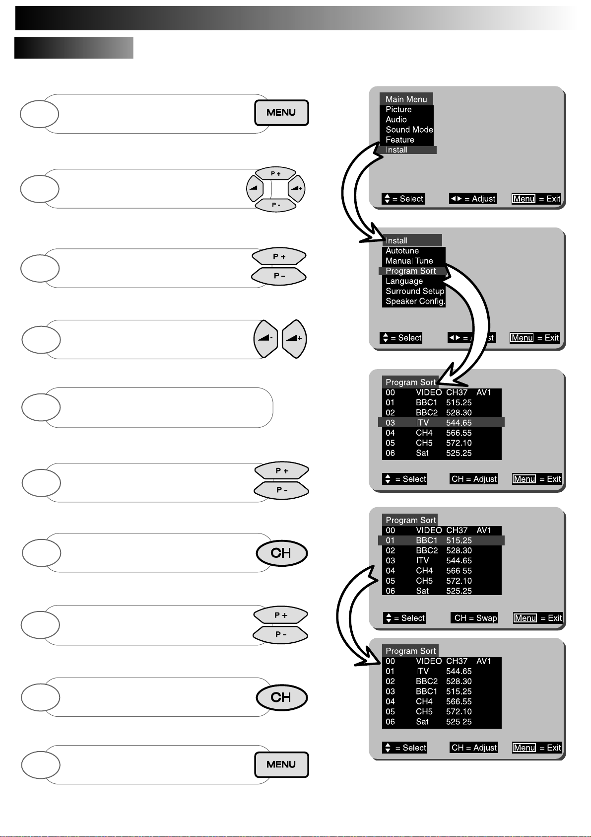
The PROGRAM SORT menu allows the user to swap programme numbers from one
location to another. If necessary follow the steps below.
Program Sort
Program Sort
8
8
In this example BBC1 on Program 1 has been selected
so that it may be swapped with Program 3 (ITV).
Press and HOLD the MENU button until Main
Menu with INSTALL is shown
Use up/down buttons to highlight INSTALL
and use the left/right
buttons to select.
Use the up/down buttons to highlight
PROGRAM SORT.
1
2
3
The PROGRAM SO RT menu is displayed.
Use the up/down buttons to highlight Program
to change (example shows Program 3 ITV)
Press the CH button to select
(selection bar turns RED in colour)
5
6
7
Use the up/down buttons to highlight Program
to be replaced (example shows Program 1
BBC1)
Once highlighted press CH key once more to
confirm selection (selection bar returns to
BLUE)
Repeat above to swap other programs, or repeatedly
press MENU button to return to
TV operation.
8
9
10
Use left/right buttons to select
PROGRAM SORT.
4
Automatic T
Automatic T
uning cont.
uning cont.
Page 9

To FINE TUNE press the up/down
buttons until the picture becomes clear.
If desired, you may manually tune this TV. There are several methods of Manual Tuning, these include Search Tuning / Fine Tuning and
Frequency or CH manual input (this requires you to know your local broadcasting frequency or CH number). This section will also deal with
items such as assigning AV sockets to program numbers and Program Naming.
This section deals with locating broadcasting stations using the Search Tuning and
combined Fine Tuning fac ility. Fine Tuning may be required after Search or Automatic
Tuning is complete.
Search T
Search T
uning / Fine T
uning / Fine T
uning
uning
9
9
The MANUAL TUNE menu is displayed
(bottom right).
Use the up/down/left/right buttons to
highlight frequency bar of
programme N” to Search Tune.
Press CH button to select
(bar turns RED)
4
5
6
When a broadcast is found either repeatedly
press the MENU button to
store and exit to TV
To continue SEARCH TUNE simply press the
left/right buttons the TV will start searching once
more..
8
9
When complete repeatedly press the MENU
button to exit, or repeat above to Search/Fine
Tune other program
numbers if necessary.
10
OR
Press and HOLD the MENU button until Main
Menu with INSTALL is shown
Use up/down buttons to highlight INSTALL
and use the left/right buttons to select.
1
2
Use the up/down buttons to highlight
MANUAL TUNE.
3
Press the left/right buttons to begin SEARCH
TUNE.
7
Manual T
Manual T
uning Procedure
uning Procedure
Page 10

Manual T
Manual T
uning cont.
uning cont.
When AV sockets are commonly used, for example, if you view camcorder recorded events
frequently, then we suggest assigning a dedicated program number on your TV. This can
be any program number that has not already been assigned. Follow the step by step guide
below.
Assigning A
Assigning A
V Prog. N”s
V Prog. N”s
Broadcasting stations transmit the signal to your TV on a particular defined frequency i.e.
525.25MHz. These frequencies can be entered manually if known, and you can obtain this
information by calling your local operator. In addition to frequency transmission a corresponding CHANNEL N” is also used e.g. CH34, and this
too can be directly input to your TV if known. (The S-- number has no function on this TV).
10
10
AV2 assigned to Program 6
Press and HOLD the MENU button until
Main Menu with INSTALL is shown. Use up/down
buttons to highlight INSTALL - select by
pressing the left/right buttons .
Use the left/right/up/down buttons to highlight the
frequency of the program number you wish to
enter.
Press the CH button on your handset
once - the column changes RED to
indicate selection.
1
3
4
Repeatedly press CH key to select CH- - or
---.--, and enter the known number using
0-9 keys.
Once the number has been entered, press the MENU
key once more and the display turns BLUE.
This is now stored. Press MENU t o exit.
5
6
Repeat above to enter other AV sockets or
repeatedly press MENU button to store and
exit to TV mode.
6
Use up/down buttons to highlight
MANUAL TUNE, select by using the
left/right buttons.
2
Use up/down buttons to highlight
MANUAL TUNE, select by using the
left/right buttons.
2
Use the left/right/up/down buttons to
highlight the AV column of the program number you
wish to use.
3
Once highlighted press the CH
button to allow changes to be entered.
4
Select between each AV mode using the
left/right buttons
5
Press and HOLD the MENU button until
Main Menu with INSTALL is shown. Use up/down
buttons to highlight INSTALL - select by
pressing the left/right buttons .
1
Entering Known Frequencies
Entering Known Frequencies
Page 11

Manual T
Manual T
uning cont.
uning cont.
After Tuning in, most broadcasting station names appear on screen i.e. BBC1, BBC2, ITV etc.. However,
you may change or add program names whenever you desire. To add or change program names follow
the simple step by step guide below.
Program Naming
Program Naming
11
11
When selected the character will blink on and off.
Press the CH button to select program name you
wish to change (the first digit will blink).
4
Once the first character has been entered select next
digit using the right button and repeat above step.
6
You may use up to 5 characters for any one
Programme Name.
Press MENU button to store.
7
Repeat above steps to assign other Program
Names or repeatedly press MENU button to exit to
TV mode.
8
Use up/down buttons to highlight
MANUAL TUNE, select by using the
left/right buttons.
2
Use the left/right/up/down buttons to
highlight the program name you wish to change.
3
Use the up/down cursor keys to scroll through the
characters.
5
Press and HOLD the MENU button until
Main Menu with INSTALL is shown. Use up/down
buttons to highlight INSTALL - select by
pressing the left/right buttons .
1
Page 12

Function Controls
CONTRAST:
BRIGHTNESS:
COLOUR:
SHARPNESS:
*HUE:
*(Hue control appears on-screen only if an NTSC signal is received via the AV sockets).
More Functions
TEXT BRIGHTNESS : This function allows the user to adjust the text brightness of On Screen Display windows and Teletext pages.
NOISE REDUCTION :Noise Reduction improves picture quality when a signal becomes weak or when viewing poorly recorded VCR tapes.
When selected a ✓ is displayed.
WHITE: This feature controls the colour temperature displayed on the picture tube.
Picture settings are controlled via the TV s on board Menu system. These levels have already been preset at the factory and should require
no adjustment. However, your personal viewing preferences may vary from these settings and alteration should be performed as follows:-
12
12
Picture Menu
Picture Sub Menu
Minimum setting
Maximum setting
To obtain the MORE sub menu highlight
MORE using the up/down cursor keys.
7
Select and adjust controls as
necessary, once complete press MENU
button repeatedly to exit
6
Press the MENU button
on your handset until the
MAIN MENU appears.
1
Use the up/down buttons to highlight
PICTURE.
Use the left/right buttons to select
the PICTURE option.
2
3
Highlight the control to be adjusted using the
up/down buttons.
Use the left/right buttons adjust your selection.
4
5
Select and adjust controls as
necessary, once complete press
menu button to exit.
8
Picture and Audio Controls
Picture and Audio Controls
Page 13

The Sound Menu is accessed via the TV s on-board MENU system, and allows the user to control such features as Volume, Bass, Treble,
Balance and Bass Boost. These settings have already been preset at the factory, however, your personal listening tastes may dif fer from those
set. Please follow the guide below for adjustment and setting.
Picture and Audio Controls
Picture and Audio Controls
Function Controls
VOLUME:
BASS:
TREBLE:
BALANCE:
NOTE: The balance control is disabled whilst in DolbyfiPro Logic and DolbyfiPro Logic Theatre modes
BASS BOOST: When selected a ✓ is displayed.
13
13
Minimum setting
Maximum setting
Left Speaker
Right & Left Speakers
Right Speaker
Select and adjust controls as
necessary, once complete press MENU
button repeatedly to exit
6
Press the MENU button
on your handset until the
MAIN MENU appears.
1
Use the up/down buttons to highlight
AUDIO.
Use the left/right buttons to select
the AUDIO option.
2
3
Highlight the control to be adjusted using the
up/down buttons.
Use the left/right buttons adjust your selection.
4
5
Page 14

Activating the 3DS sound spatializer is simple, press the button marked on the handset to activate, one press more will de-activate.
When activated a ‘ ‘ symbol appears in the top right hand corner of the screen indicating that 3DS is on. When de-activated the
symbol is displayed on-screen (see below).
INTERNAL SPEAKER OPTION
Through innovative design and complex internal circuitry, HI TACHI have produced this television which recreates superb Dolby Pro
Logic cinematic sound. However, to enhance your viewing pleasure when using only the TV s own internal speakers, we have created
the 3DS system (3 Dimensional Spatial sound). The 3DS system gives a much wider spread of sound from the TV giving the
impression of sound coming from the sides of the room rather than the in built speakers, whilst the important centre dialogue channel
is unaltered, still appearing to come from the centre of the screen.
3DS mode activated
3DS mode de-activated
NOTE: In order to appreciate the
ef fect of 3DS it is essential that
you are listening to at least a
stereophonic program with active
left or right information. For
example, certain programs
containing only speech will appear
to have no effect when 3DS mode
is selected.
14
14
EXTERNAL SPEAKER OPTION
Place the external speakers around the television in a position which best suits your environment. Connect the left sided
speaker connection to the socket marked L at the rear of your television, and connect the right sided speaker to the socket
marked R at the rear of your television (see illustration)
.
right external speaker left external speaker
Please Note
Once speakers are connected, you will lose sound from
your TV s internal speakers. For more details on sound
see Speaker Configuration Menu section.
rear TV socket
connections (
IF FITTED)
HIT
HIT
ACHI 3DS System
ACHI 3DS System
L
R
2 x 12W 8
L
R
2 x 12W 8
Page 15

The Speaker Configuration menu allows the user to access various centre speaker modes. This is particularly useful if an external amplifier
is connected to the Centre PHONO Socket. In addition to these options, you may want to replace the TV s internal speaker sound to a full
external amplified speaker setup. In this case the user can mute the TV s speakers from within the Speaker Configuration Menu, allowing
sound only to be heard through the external amplified sound sources. Follow the step by step guide below:
Follow the guide below describing options with and without external amplifiers connected:
Option 1: (PHANTO M ) If you do not have any external amplifiers
connected to the TV then select the PHANTOM mode permanently.
Phantom allows the TV to create centre dialogue information using the
TV s left and right internal speakers. (NORMAL and WIDE have no
effect when there are no external centre amplifiers connected [See
Notes below]).
Option 2: (PHANTO M ) If there are external surround amplifiers
connected but no centre amplifier connected, then select PHANTO M
mode. This again allows the TV to create centre dialogue information
using the left and right internal speakers.
(NORMAL and WIDE have no effect when there are no external centre
amplifiers connected [See Notes below]).
Option 3: (NORMAL) In option 3, it is presumed the user has a limited
bass response centre amplifier connected. If you feel that this best
describes your setup then select NORMAL. This mode will anchor
dialogue to your centre amplifier whilst relaying bass response through
the TV s internal left and right speakers [See Note below].
Option 4: (WIDE) This option assumes there is a good bass response
centre amplifier connected to your TV. If this option describes your setup
then select WIDE from the Speaker Configuration Menu. In this mode all
bass response and dialogue is fed to the centre amplifier [See Notes
below].
Speaker Configuration Menu
Speaker Configuration Menu
Speaker Configuration Menu - note the displayed
information window, th is b riefly describes the mode you
have selected.
15
15
Press 'MENU' button
to exit
Set
'Centre Channel' option
to PHANTOM
Set
'Centre Channel' option
to NORMAL or WIDE
Do you have an external
CENTRE
Speaker
YES
NO
Select 'Speaker Config.'
using the up/down keys.
Now follow guide below
Do you have external
LEFT and RIGHT
Speakers
YES
NO
Set
'Mute Internal Speakers?'
to off i.e.
Set
'Mute Internal Speakers?'
to on i.e. ✓
Highlight 'Speaker Config.'
using the up/down keys
Select INSTALL using the
right/left buttons
Highlight INSTALL using the
up/down buttons
Use up/down buttons to select
'Dolby Pro Logic'.
Highlight 'Sound Mode' using
the up/down handset buttons.
Select 'Sound Mode' using
the left/right handset buttons.
Press the Menu key
(until Main Menu appears).
De-activate the 3DS system
( see page 14 )
Now press MENU key to exit to
Main Menu
Press & Hold MENU button to view
Main Menu with INST ALLATION.
PLEASE NOTE:
In 2 speaker mode i.e. using only internal TV speakers
with 3DS activated, the CENTRE channel option will
display PHANTOM and cannot be changed to any other
mode.
Whilst in HALL or STEREO modes the Centre Channel
option displays OFF , and also cannot be changed to
any other mode.
Page 16

Sound Mode Menu
Sound Mode Menu
16
16
The Sound Mode selection menu allows the user to select between various sound effects. These ef fects enhance your
viewing pleasure, particularly when viewing movies, sports events and concerts etc.. The guide below provides a description of the Sound
Modes and what mode is suggested for viewing particular programs.
DOLBY PRO LOGIC (Internal Speaker Mode)
In this mode virtual surround sound can be created using just the TV s internal speakers. Activate 3DS to enable virtual surround sound. This mode is also
particularly suitable for films and programmes that display the DOLBY SURROUND caption. (This mode is recommended for the majority of TV viewing).
DOLBY PRO LOGIC (External Surround Amplifier Mode)
In this mode full cinematic sound is achieved using the TVs internal circuitry, combined with your choice of external surround sound amplifier and speakers.
(Please Note: The 3DS system should be de-activated for this mode see HITACHI 3DS System Section ).
This mode is particularly suited to action movies and dramas that display the DOLBY SURROUND caption.
DOLBY PRO LOGIC (Theatre)
This mode creates a larger sound field for those programmes that have little surround sound content. It is particularly effective when used in conjunction with
external surround amplifiers, however, if you are using the TV internal speakers only, activating the 3DS system will also provide a pleasing aural sound.
HALL (External Surround Amplifier Mode)
HALL mode creates an ambient sound effect, especially when viewing mono broadcasts. Again this mode is very effective when used in conjunction with external
surround amplifiers. Activate the 3DS mode whilst using the TV s internal speakers to obtain equally pleasing sound from your TV.
Select this mode when viewing classic films or drama events, which were recorded in mono.
STEREO
When STEREO mode is selected, the TV produces high quality stereo sound. Select this mode when viewing general TV programs and films.(3DS sound can
be activated in this mode to provide a much wider stereo image).
NOTE:
1. Dolby Pro Logic can only be achieved by the addition of an external surround sound amplifier and speaker system. Sockets have been provided
to enable you to do so if you wish. (Please see TV CONTROLS OVERVIEW section of this manual. Consult your HITACHI dealer with regards to
purchasing external equipment).
You can, however, enjoy a surround sound experience, without the need to add external equipment, from your television s 3DS surround sound
system, developed by HITACHI.
3DS uses the surround channel information which has been separated from the original sound track by the integral Dolby Pro Logic decoder and
processes it, before feeding back to the internal TV speakers.
2. Activating 3DS whilst using external surround amplifiers will cause the external surround channels to mute.
3. Activating and de-activating 3DS can only be achieved whilst no menus are on-screen (see HITACHI 3DS
System Section ).
This ef fect produces NICAM digital stereo sound from the TV.
Use this mode for the majority of TV viewing. When selected the
STEREO symbol is displayed in the top right hand corner of the
TV screen as shown.
See also Hitachi 3DS System.
In monaural mode the TV transmits a single sound source. The TV will
automatically select this sound when a mono signal is found. Some stereo
signals can become poor in adverse weather conditions, and mono should be
selected to avoid poor sound. Use the key to switch to mono (the
symbol below appears when switched).
Stereo
Stereo
Monaural
Monaural
Additional NICAM features
Additional NICAM features
oo
After selecting the desired sound mode, exit to
T V mode by repeatedly pressing the MENU
key.
4
Press the MENU button
on your handset until the
MAIN MENU appears.
1
Press the YELLOW colour coded button to view
SOUND MODE menu.
2
Select desired sound mode by using the
up/down buttons.
3
Page 17

At Hitachi we appreciate the fact that not all living area s are the same, therefore the Surround Setup menu allows the user to balance the
sound by adjusting the volume level to each channel, thus accommodating various room layouts.
In addition to this the menu also has a Surround Delay mode, this enables the viewer to select the optimum surround sound delay
depending on your seating position relative to the TV (not available when 3DS is active).
Please note that the Surround Set-up menu is only available in DolbyfiPro Logic and DolbyfiPro Logic Theatre modes, and thus will
automatically default to DolbyfiPro Logic when selected.
NOTE:When the SET-UP menu begins, the TVs sound is replaced with a noise signal. This is easier to balance than normal TV sound, and
will cycle between the centre, left, right and surround channels (the centre channel cannot be adjusted unless an external amplifier for the
centre channel is connected and is adjusted from PHANTOM to WIDE or NORMAL modes in the Speaker Config. menu). If 3DS is active
the surround PHONO output becomes muted.
When the TV automatically cycles through the various sound channels, we suggest that you listen to the TV sound for a few moments
before adjusting any of the channels. By doing this you may be able to determine which channel needs adjusting. Once you have adjusted
the selected level, leave the TV to cycle through the Set-up menu a few times more, this will then determine whether you have applied the
correct amount of volume level to the selected sound channel.
The Surround Delay mode enables the viewer to set the optimum surround sound delay from the TV. There are
three levels to select and these are dependant on how close your viewing position is to the TV. Each setting is
displayed as a millisecond value (ms) and are configured as 15ms, 20ms and 25ms. If you feel that your
seating position is relatively close to the TV (example 1 below), then set the Surround Delay to 15ms. The 20ms setting should be used if
you believe your seating position is midway between the TV and the rear sound source (example 2 below). Set the Surround Setup to 25ms
if the seating position is relatively close to the rear sound source (example 3 below). Setting these modes is explained below.
Please note that 3DS should be de-activated before the Surround Delay mode is set.
Surround Delay
Surround Delay
17
17
example 1
example 1
example 2
example 2
example 3
example 3
TV
Y our seating
position
Surround
Speakers
Surround
Speakers
Enter the Surround Setup Menu as described
above and select
Surround Delay using the up/down
cursor keys
Use handset buttons left and right to select
between 15, 20 and 25ms.
1
2
Use the left/right/up/down buttons to adjust the
values of your choice
3
Repeatedly press MENU key to exit
4
Use up/down buttons to highlight
SURROUND SETUP, select by using the
left/right buttons.
2
Repeatedly press MENU key to exit
3
Press and HOLD the MENU button until
Main Menu with INSTALL is shown. Use up/down
buttons to highlight INSTALL - select by
pressing the left/right buttons .
1
Surround Setup Menu
Surround Setup Menu
Page 18

✔
Option 2 describes and illustrates the connection of Rear, Front and Centre Surround Amplifiers &
Speakers.
1. Switch off TV.
2. Connect Surround , Left, Right and Centre speakers as shown and position closely to illustration below.
3. Switch TV on.
4. De-activate 3DS and follow instructions in the Speaker Configuration Menu Section to obtain Speaker Configuration Option, and
ensure Internal Speakers A R E
muted i.e. ( ), also set Centre Channel to WIDE or NORMAL.
5. Use the Surround Set-up Menu to adjust the volume level on the Surround Speakers and Centre speaker if required.
Option 1 describes and illustrates the connection of Rear Surround Amplifiers & Speakers.
1. Switch off TV.
2. Connect Surround speakers as shown and position as indicated in the illustrations below.
3. Switch TV on.
4. Follow instructions in the Speaker Configuration Menu Section t o obtain Speaker Configuration Option, a n d ensure Internal
Speakers ARE NOT
muted i.e ( ), also set Centre Channel to PHANTO M .
5. Use the Surround Set-up Menu to adjust the volume level on the Surround Speakers if required.
! IMPORT
ANT ! The 18V power output socket on the rear of this TV is specifically designed for Hitachi Accessories. Under no
circumstances connect any other accessory to this socket, as this could cause serious irreparable damage to your equipment.
Before attempting to connect any external equipment, ensure that the TV is switched O F F
.
OPTION 2
OPTION 2
! 18V DC Output !
Front Right Amp & Speaker
Rear Surround Amp & Speaker
Centre Amp & Speaker
Front Left Amp & Speaker
In this configuration full Dolby Pro Logic Sound is achieved using 5 external speakers.
If desired you may want to customise your TV by adding external surround speakers. This TV will accommodate external surround speaker
systems via external sockets on the rear of the TV. The addition of external surround speakers will enhance your viewing and listening pleasure
even further, and we strongly recommend you purchase HITACHI systems to compliment your HITACHI TV (contact your dealer for advice).
The illustrations (below) will guide you on the correct installation and settings for external surround speaker set-ups.If you decide to purchase
additional amplifiers and speakers then please follow these simple guidelines listed below:
1. If you have purchased just 2 amplifiers and speakers then these are best installed as rear surround speakers, as the TV will use its own
internal speakers to create the front left, right and centre channels.
2. Please ensure that you purchase and install the correct rated range of amplifier and speaker for the TV - (front- centre speakers 10
W att or greater) and (rear surround 5 Watt or greater). Your HITACHI dealer can advise you on the correct amplifier and speaker
choice for your TV.
OPTION 1
The TV uses internal speakers to provide left and right channels, and also
creates its own centre channel. The rear surround speakers enhance your
listening pleasure.
Wherever possible, locate surround speakers at or just
above head height for best results.
Front Speaker
Rear Speaker
& *Stand
Rear Speaker
& *Stand
Surround
Speaker
& *Stand
Surround
Speaker
&*Stand
Front Speaker
*Speaker Stands are available from your Hitachi dealer.
Centre Speaker
! 18V DC Output !
Surround Amp & Speaker
Connecting External Audio Equipment
Connecting External Audio Equipment
18
18
Page 19

The Solid Background feature controls the appearance of the OSD (On Screen Display) window
environment, with either a solid or transparent appearance to the OSD. There are two modes to select
from and these are simply ON and OFF. Follow the guide below.
This feature is used to set the condition of Scart 2 Audio/Video input socket. If, for example, you regularly connect
external equipment such as S-VHS (Super VHS) Video recorders or camcorders to AV2, then the TV can be set to
S AV mode to accommodate such equipment. Standard AV mode can also be set if desired.
The Feature Menu also incorporates a Sleep Timer Facility. This allows the user to input a set amount of
time before the TV automatically shuts down in to Stand by mode. The amount of time is input in 5 minute intervals, to a maximum of 120
minutes ( 2 hours). When there is only 60 seconds remaining a countdown appears in the top right hand corner of the screen.
Solid Background
Solid Background
Scart2 Auto Mode
Scart2 Auto Mode
Sleep T
Sleep T
imer Function
imer Function
W ith Solid Background
deselected the OSD window
becomes transparent, allowing
you to view the TV picture behind
the OSD.
W ith Solid Background selected
the OSD window becomes solid.
An example of the Sleep Timer function with 25
minutes entered is shown.
19
19
NOTE: The 4:3 default mode relates to Wide Screen modes. Please refer to the W ide Screen Modes Section for instructions
on settings
Adjust the controls ON or OFF using
the up or down
handset buttons. Press MENU to
exit.
4
Press the MENU button
on your handset until the
MAIN MENU appears.
1
Press the BLUE colour coded
button to view FEATURE menu.
2
Select SOLID BACKGROUND mode
by using the up/down buttons.
3
Adjust the controls by using the left
or right handset
buttons. Pres MENU to exit.
4
Press the MENU button
on your handset until the
MAIN MENU appears.
1
Press the BLUE colour coded
button to view FEATURE menu.
2
Select SCART2 AUTO MODE mode
by using the up/down buttons.
3
Adjust the time value by using the left
or right handset
buttons. Press MENU to exit.
4
Press the MENU button
on your handset until the
MAIN MENU appears.
1
Press the BLUE colour coded
button to view FEATURE menu.
2
Select SLEEP TIMER mode by using
the up/down buttons.
3
Feature Menu
Feature Menu
Page 20

20
20
WWide Screen Modes
ide Screen Modes
example 1
example 2
Auto mode automatically detects various screen formats that are transmitted in either
conventional (4:3) or wide screen (16:9/14:9L). After detecting which signal is being
transmitted the TV will automatically switch to the correct screen ratio.
In example 1 (left) a 4:3 conventional picture format is shown, note the black bars to
the sides of the screen, this is consistent with screen compression.
4:3 mode can also be manually selected if desired.
AUT
O
The various screen modes below and on Wide Screen Modes Section are available on this model. Each of these modes are accessed
using the 16:9 button on your handset
example 4
Panoramic mode emulates that of a Wide Screen broadcast for 4 x 3 transmissions.
This is achieved by maintaining the proportions of the centre of the screen while
extending the images on the sides of the screen
(example 4).
This mode is generally recommended if AUTO is not selected.
PANORAMIC
A U TO mode can also detect 14:9L ratio signals, when this mode has been selected
thin black bars appear to the sides of the screen (example 3).
NOTE: Other screen formats may be transmitted by certain
broadcasters, these are 14 x 9L T rue W ide Screen and 16 x 9L/14 x 9L with
subtitles. Your TV is able to detect these formats and adjust the set automatically
(subject to WSS transmitting).
Example 2 (left) illustrates a 16:9 W ide Screen picture format. This type of picture
fills the entire TV screen. The 16:9 mode can also be
manually selected if desired.
Hitachi recommend that AUTO i s selected for the majority of TV viewing.
NOTES: The function of the AUTO mode is dependent on whether the Wide Screen
Signalling (WSS) is transmitting, check with your local operator for availability.
When WSS is not active the picture mode will default to the Feature settings (see
Wide Screen Modes Section )
example 3
Page 21

21
21
Some modes can also be manually selected if some pictures appear distorted or stretched, or subtitle
information becomes lost. Follow the guide below to apply the correct setting.
The 16:9 Letterbox mode is used to expand a 16:9 letterbox style picture so that
it uses the full screen to display the picture. Letterbox type pictures are
identifiable by the black bars that appear on the top and bottom of the screen
and some objects appear stretched (see example 5). Once selected, the 16:9L
mode displays the picture as example 2 on Wide Screen Modes Section .
16 x 9L
If viewing movies or programmes containing screen subtitles whilst in
16 x 9L or 14 x 9L modes, the subtitle may become lost to the bottom of the screen.
To overcome this problem, simply press the SUBTITLE button once.The
SUBTITLE feature compresses the bottom of the screen allowing the subtitles to be
viewed, as in example 7.
If, however, you wish to view Teletext subtitles a further press of the SUBTITLE
button is required, this will then restore the screen to it s original setting.
example 5
example 6
example 7
When viewing pictures in the 14:9L Letterbox mode (example 6) thin black bars
appear at the top and bottom of the screen, and images become slightly
elongated. By selecting 14:9L mode the user can expand the TV picture to display
more of the screen (see example 3 above).
14 x 9L
NOTE: Whatever Wide Screen mode was set before the TV is switched off will be the same condition when it is switched back on.
The references to the Wide Screen modes are purely for guidance purposes only - your preferences may vary to those listed.
MANUAL SETTINGS
WWide Screen Modes
ide Screen Modes
The 4:3 default setting in the FEATURE Menu allows you to set which screen mode the TV defaults to
when the AUTO function is selected but WSS (Wide Screen Signalling) is not transmitting. This allows
the user to select between the various wide screen modes as a default.
4:3 Default
4:3 Default
Adjust thetime value by using the left
or right handset
buttons. Press MENU to exit.
4
Press the MENU button
on your handset until the
MAIN MENU appears.
1
Press the BLUE colour coded button to
view FEATURE menu.
2
Select 4:3 DEFA U LT mode by using
the up/down buttons.
3
Page 22

2 x 12W 8
L
R
SA
TELLITE CONNECTION:
There are two basic methods of connecting a satellite system to your TV. Method 1 explains connection of
satellite equipment directly to the TV, where as Method 2 refers to connection via a VCR.
CAMCORDER CONNECTION: Connecting a camcorder to your TV is simple. Firstly, identify the type of camcorder and it s connecting
plugs. If it is a standard 8mm type camera then it is likely to have RCA type sockets. If, however, you have S-VHS or Hi8 type camera then
this may have a S-VHS/Hi8 plug, and this will have to be placed in the corresponding SVHS/Hi8 socket on the TV. Open the front control panel door on the TV, and connect your
equipment as shown in the illustration below. Switch your TV on, and repeatedly press the
TV/AV button on your handset until AV3 or SAV3 (for S-VHS equipment) is displayed onscreen. Now begin playback operation of your equipment.
Connecting External A
Connecting External A
V Equipment
V Equipment
Your TV has various input sockets for external equipment such as Video Cassette Recorders, Satellite Receiver/Decoder, Camcorders,
Computer Equipment etc.. Equipment that is connected temporarily i.e. Camcorders can be connected via the front control panel input sockets.
However, equipment such as VCR s and Satellite IRD s, that are more or less permanently connected to your TV, are connected via the AV1 or
AV2 scart sockets on the rear of the TV.
*S-VHS/Hi8 Plug
V ideo In
* RC A Plug
Audio In (Right)
R C A Plug
Audio In ( Left)
R C A Plug
*Scart Lead to AV2 on TV
Aerial
RF lead to Aerial
Satellite LNB lead
RF lead from
Satellite to TV
COMPUTER EQUIPMENT:If computer equipment is to be connected to this TV, use AV1 as the RGB input
socket located on the rear of the TV and select RGB using the RED colour coded key on your handset.)
PLEASE NOTE: Prolonged use of computer equipment or games on this TV may cause permanent damage to your picture
tube. To avoid such damage, reduce the brightness and contrast to an acceptable minimum level and limit the duration of
equipment operation.
AV3
22
22
* If your camcorder has both S-VHS/Hi8 and RCA type plugs, then connect
all plugs except the Video In RCA p lug.
METHOD 1
Page 23

Connecting External A
Connecting External A
V Equipment
V Equipment
*Scart Lead to AV1 on TV
*Scart Lead from Satellite
to VCR
Aerial
Satellite LNB lead
RF lead from VCR to TV
RF lead from
Satellite to VCR
VCR
METHOD 2
HEADPHONE CONNECTION:
To use headphones with this TV, simply open the front control cover door and insert the headphone jack plug (3.5mm) into the
corresponding socket marked . The TV sound will then be switched to the headphones.
3.5mm Headphone jack socket
(a suitable adaptor is required for larger headphone plugs).
NOTE: S-VHS video equipment should be connected to the AV2 Scart socket located on the rear of the TV. A
dedicated program number may then be assigned to AV2, allowing easier access to view external equipment broadcasts.How to assign AV
sockets to dedicated program numbers is explained in the Manual Tuning Section . Alternatively,
repeatedly press the TV/AV button on your handset until SAV2 is displayed on-screen. Now begin playback
operation of your equipment.
23
23
RF lead to Aerial
L
R
2 x 12W 8
Page 24

The remote control handset supplied has several different functions. These
functions are mainly used for operations whilst in teletext mode. The Teletext modes and
functions are in *bold italic type and all
functions are briefly explained opposite.
Handset Controls
Handset Controls
24
24
Page 25

1
2
3
4
5
6
7
8
9
10
11
12
14
15
16
17
18
19
20
21
22
23
24
25
26
27
28
29
30
31
32
33
34
Stand-by button
Used to switch the TV on and off for short periods of time.
Recall/Hold
Press Recall to view current TV status. Press Hold to freeze Teletext page.
Dual Language
This button allows the user to select a dual language function (subject to availability) and switches from
Mono to Stereo reception, it also has a colour coded teletext function and OSD function.
AV Input
The TV/AV button allows the user to select either a TV or external source signal i.e. a camcorder etc..This button also has
a colour coded teletext function and OSD function.
Television
This enables the viewer to return to normal TV operation.
Teletext
When pressed this button enables the Teletext service.
P+/Cursor up
When in normal TV operation this button allows the user to step up programme numbers in sequence. In MENU mode
this button is the cursor up key.
V ol-/Cursor left
When in normal TV operation this button allows the user to reduce the TV volume. In MENU mode this button
is the cursor left key.
P-/Cursor Down
When in normal TV operation this button allows the user to step down programme
numbers in sequence. In MENU mode this button is the cursor down key.
EPG/Index
The INDEX function is used whilst in Fastext mode and displays the magazine page on view.The
EPG function is not available on this model.
Update
The Update button restores the TV screen whilst a Teletext page is searched.
Volume up
Digits 0 to 9
Used for direct programme selection (enter a second digit within 2 seconds for programme numbers
above 10 i.e. to obtain programme number 29 enter 2 and then 9). Teletext 3 digit entry .
Swap
In TV mode swaps between previous and current programme numbers. I n Teletext mode this feature
allows the user to recall the last 4 Teletext pages.
Stop
Press to stop the VCR tape.
V ideo Stand-by Used to switch the VCR on and off for short periods of time.
Rewind Press to rewind a VCR tape.
Play Press to play a VCR tape.
16:9/Expand
Used to select between Wide Screen formats. Used to expand text pages.
Mute This feature allows the user to mute the sound temporarily.
Stereo
Press to select between Stereo Normal and Stereo Wide modes, also has a colour coded teletext
function and OSD function.
Clock
This button allows the user to display the current time on-screen, also has a colour coded teletext function
and OSD function.
Subtitles
Allows the user to access a subtitle service directly (subject to Subtitle service broadcasting).
Vol+/Cursor Right
When in normal TV operation this button allows the user to increase the TV
volume. In MENU mode this button is the cursor right key.
Menu
The MENU button when pressed allows the user to access the TV s menu system.
Reveal
Used whilst in Teletext mode to reveal hidden pages i.e. quiz pages etc.
Program up
When in normal TV operation this button allows the user to step up programme numbers in sequence. In MENU mode
this button is the cursor up key.
Program Down
When in normal TV operation this button allows the user to step down programme
numbers in sequence. In MENU mode this button is the cursor down key.
Frequency Allows the user to directly input known broadcasting CH or frequency numbers.
Forward
Press to fast forward a VCR tape.
When in normal TV operation this button allows the user to increase the TV
volume. In MENU mode this button is the cursor right key.
13
Volume down
When in normal TV operation this button allows the user to decrease the TV
volume. In MENU mode this button is the cursor left key.
OSD (On Screen
Display).
Handset Functions
Handset Functions
25
25
TELETEXT FUNCTIONS ARE SHOWN IN BOLD ITALIC TYPE.
NO FUNCTION
NO FUNCTION
NO FUNCTION
Page 26

TTeletext Operation
eletext Operation
VCR Operation
VCR Operation
Your handset incorporates controls for operation of HITACHI Video Cassette Recorders. These controls are STANDBY, P LA Y, ST OP, FAST
F O RW ARD, and REVERSE, and are located on the bottom of the handset.
To switch your VCR on or off simply press the VCR Standby button
To halt a cassette tape press the STOP button .
To rewind a cassette tape press REW button.
To begin playback of a cassette tape press the PLAY button.
To fast advance a cassette tape press F/FWD button.
26
26
Teletext operation is entered by pressing the TEXT button on your handset.
A page similar to the one shown on the right will appear. The main page contains
numbered topics that are accessed by entering the corresponding three digit code
on your handset.
In addition to the above system, at the bottom of the page there are four colour
coded popular topics i.e. TV Guides, Weather, Sport etc., however, these may vary
between each broadcasting station. To access these topics simply press the
corresponding colour coded keys on your handset .
By pressing the P+ or P- keys you may step up or down a page respectively.
If a mistake occurs while entering a number then simply re-enter the desired
number.
FAVOURITE PAGE OPTIONS
The TV is capable of storing up to 4 favourite pages. These pages could be your
favourite sport or TV page etc., and are accessed by pressing one of the colour
coded keys on your handset.
To enter a favourite page first access the TEXT mode by pressing the TEXT key
on the handset. Now enter the favourite page mode by pressing the MENU button
on your handset (the MENU button allows the user to toggle between
FASTEXT and FAVOURITE PAGE modes).
Enter the colour coded key you wish to use as the first favourite page..
Now enter the page number you wish to assign to the desired colour coded key using the 0-9 buttons on your handset.
Once you have completed this step you must now store your selection in the TV s memory. Simply press and hold the
selected colour coded key until the entire bottom fastext bar turns white. This is now stored.
If desired, another three favourite pages may be entered by following the above method, utilising the existing colour coded keys.
To view a Favourite Page simply press the MENU key whilst in FASTEXT and press the desired stored page using the Colour Coded keys on the
handset.
The 4 Fastext Topics are shown on the bottom of the screen
Page 27

TTrouble Shooting Guide
rouble Shooting Guide
The guide below is intended to help the user to identify common problems which may be encountered during the setup of this TV. If a problem
still exists after referring to this guide, please consult your dealer immediately. Under no circumstances remove the rear cover of this TV. There
are no user serviceable parts inside and you will be exposed to high voltages, which could cause a severe or fatal electric shock.
Problem Identification Possible Reason Remedy
Snowy Picture - Poor Sound
Multiple Images - Sound OK
Intermittent Interference
No Picture and/or No Sound
Aerial has moved out of position Re-align aerial.
Corroded or poor aerial connections. Make new connections or
renew lead.
Connection of RF lead to TV poor. Make new connection and/or
change RF plug.
Adverse weather conditions. None.
Transmitter problems. Check with local Operator.
Aerial has moved out of position. Re-align aerial.
TV not tuned correctly. Re-tune or Fine tune TV.
Adverse weather conditions. None.
Transmitter problems. Check with local Operator.
Magnetic interference from electrical Check devices for shielding
or mechanical motors, fluorescent and renew if necessary or
lights, portable radios etc.. move further from TV.
TV may be in AV mode. Press AV/RED button
repeatedly or 0-9 buttons to
return to TV mode.
TV in Stand-by. Press 0-9 buttons.
Picture/Sound controls set to Check Picture/Sound
minimum. controls.
Aerial plug removed from TV socket Re-plug aerial lead to socket.
Incorrect Speaker mode selected Ensure the correct Speaker
Configuration is selected.
Q) My TV fails to switch on.
A) Check that plug is connected to socket and switched on. Check fuse and make sure TV is not in Stand-by mode (see below).
Q) My remote control handset does not work.
A) Ensure there are no obstructions between the handset and the TV infra red lens, or the batteries may be exhausted - replace
with new.
Q) The handset won t control my VCR.
A) The handset is only programmed to operate Hitachi VCR s.
27
27
Page 28

28
28
Thank You for purchasing this Hitachi Television.
In the unlikely event that this product should develop a fault, we undertake to repair or
replace any part of the product which fails due to a
manufacturing defect within 12 months of the date of purchase
provided that...
1. the product has been installed and used only in accordance with the instructions
supplied with the product.
2. the product has not been repaired, maintained, or modified by any
person other than a Hitachi authorised dealer.
3. the product serial number has not been removed or altered.
this guarantee does not apply to a product acquired second hand or for commercial or
communal use.
this guarantee does not cover the replacement of exhausted batteries, the adjustment of
user controls, or aerial alignment.
any parts replaced under this guarantee shall become the property of Hitachi Home
Electronics (Europe) Ltd,
please note that evidence of the date of purchase will be required before any service
under this guarantee is carried out
Use the boxes provided below to record your TV s Model and Serial Number - these are
found on the rating plate located on the rear of the TV. Also, record where and when you
purchased this T. V. This information will help any future queries you may have and should
be used in all
correspondence with Hitachi service centres.
SERIAL NUMBERMODEL DEALER/STOR E DATE PURCHASED
This guarantee does not affect your statutory rights.
In all cases of difficulty please
consult your Hitachi dealer.
Page 29

TTechnical Specifications
echnical Specifications
TV Standard........................................................................................................................... 625 line single standard
Channel Coverage................................................................................................................. UHF channels
Aerial Impedance................................................................................................................... 75 W unbalanced
Picture Tu bes......................................................................................................................... 28 - 66 cm type
32 - 76 cm type
Mains Voltage......................................................................................................................... 220 - 240V AC 50 Hz
Internal Speakers................................................................................................................... 6 x 12 cm type x 2
Power Consumption........................................................................................ 28 models 120W approx
32 models 130W approx.
Weight...............................................................................................................28 models 34 kg approx
32 models 51 Kg approx
Dimensions (W x D x H)....................................................................................28 models 790 x 525 x 515
32 models 879 x 569 x 554
Remote Control Batteries......................................................................................................2 x HITACHI SUM-3 /equivalent AA
SCART SOCKET AV1
SCART SOCKET AV2
PIN No. FUNCTION
AUDIO OUT (RIGHT)
AUDIO INPUT (RIGHT)
AUDIO OUT (LEFT)
GROUND (AUDIO)
GROUND (BLUE)
AUDIO INPUT (LEFT)
BLUE INPUT
SWITCHING INPUT
GROUND (GREEN)
NOT USED
GREEN INPUT
NOT USED
GROUND (RED)
GROUND (BLANKING)
RED INPUT
STATUS (BLANKING) INPUT
GROUND (VIDEO)
GROUND (VIDEO)
COMPOSITE VIDEO OUTPUT
COMPOSITE VIDEO INPUT
GROUND
1
2
3
4
5
6
7
8
9
10
11
12
13
14
15
16
17
18
19
20
21
1
2
3
4
5
6
7
8
9
10
11
12
13
14
15
16
17
18
19
20
21
PIN No. FUNCTION
AUDIO OUT (RIGHT)
AUDIO INPUT (RIGHT)
AUDIO OUT (LEFT)
GROUND (AUDIO)
NOTUSED
AUDIO INPUT (LEFT)
NOTUSED
SWITCHING INPUT
NOTUSED
NOT USED
NOTUSED
NOT USED
CHROMINANCE GROUND
NOTUSED
CHROMINANCE INPUT S VHS
NOTUSED
GROUND (VIDEO)
GROUND (VIDEO)
COMPOSITE VIDEO OUTPUT
COMPOSITE VIDEO OR
COMPOSITELUMINANCE S VHS
GROUND
S-VHS SOCKET
PIN FUNCTION
1 Chrominance input
2 Luminance input
3 Chrominance ground
4 Luminance ground
5 Frame ground
1
2
4
3
5
Specifications are subject to change without notice. Weight and dimensions shown are approximate.
29
29
Software Notice
It is prohobited for the end user of this product to copy, reverse engineer or reverse compile the software included therein save to the extent permitted
by law.
20 18 16 14 12 10 8 6 4 2
21 19 17 15 13 11 9 7 5 3 1
20 18 16 14 12 10 8 6 4 2
21 19 17 15 13 11 9 7 5 3 1
Page 30

30
30
Hitachi are signatories to the commitment made by the consumer
electronics industry on reducing energy consumption by televisions and
video recorders on standby.
Even though your TV has a low power consumption, you can reduce
waste to zero if you switch of f the set at the mains after use. Your TV
should certainly be switched off overnight or when you are away from
home. Other factors should also be considered when operating your TV.
Reducing volume settings to sensible levels can reduce power
consumption as well as reducing noise pollution, and
reducing contrast can provide a more pleasing picture as well as
reducing power consumption.
Hitachi Home Electronics (Europe) Ltd. manufacturing site in Wales is a
BSI Registered Company, and has been assessed to ISO 9001 Quality
Management Standard, certificate FM32366. Your television has been
manufactured under the Environmental Quality Management Standard
ISO14001,
certificate EMS 36168.
The paper used for this Users Guide has been produced from sustainable
forests, part of Hitachi s on going commitment to the global environment.
Environmental Notice
Page 31

Notes
Notes
Page 32

Hitachi, Ltd. Tokyo, Japan
International Sales Division
THE HITACHI ATAGO BUILDING,
No. 15 –12 Nishi Shinbashi, 2 – Chome,
Minato – Ku, Tokyo 105-8430, Japan.
HITACHI EUROPE LTD,
Whitebrook Park
Lower Cookham Road
Maidenhead
Berkshire
SL6 8YA
UNITED KINGDOM
Tel: 01628 643000
Fax: 01628 643400
Email: consumer-service@hitachi-eu.com
HITACHI EUROPE GmbH
Munich Office
Dornacher Strasse 3
D-85622 Feldkirchen bei München
GERMANY
Tel: +49-89-991 80-0
Fax: +49- 89-991 80-224
Hotline: +49-180-551 25 51 (12ct/min)
Email: HSE- DUS.service@hitachi-eu.com
HITACHI EUROPE srl
Via Tommaso Gulli N.39, 20147
Milano, Italia
ITALY
Tel: +39 02 487861
Tel: +39 02 38073415 Servizio Clienti
Fax: +39 02 48786381/2
Email: customerservice.italy@hitachi-eu.com
HITACHI EUROPE S.A.S
Lyon Office
B.P. 45, 69671 BRON CEDEX
FRANCE
Tel: 04 72 14 29 70
Fax: 04 72 14 29 99
Email: france.consommateur@hitachi-eu.com
HITACH EUROPE AB
Egebækgård
Egebækvej 98
DK-2850 Nærum
DENMARK
Tel: +45 43 43 6050
Fax: +45 43 60 51
Email: csgnor@hitachi-eu.com
Hitachi Europe Ltd
Bergensesteenweg 421
1600 Sint- Pieters-Leeuw
BELGIUM
Tel: +32 2 363 99 01
Fax: +32 2 363 99 00
Email: sofie.van.bom@hitachi-eu.com
www.hitachidigitalmedia.com
Tel: 03 35022111
HITACHI EUROPE S.A.
364 Kifissias Ave. & 1, Delfon Str.
152 33 Chalandri
Athens
GREECE
Tel: 1-6837200
Fax: 1-6835964
Email: service.hellas@hitachi-eu.com
HITACHI EUROPE S.A.
Gran Via Carlos III, 101- 1
08028 Barcelona
SPAIN
Tel: 93 409 2550
Fax: 93 491 3513
Email: atencion.cliente@hitachi-eu.com
HITACHI Europe AB
Box 77 S-164 94 Kista
SWEDEN
Tel: +46 (0) 8 562 711 00
Fax: +46 (0) 8 562 711 13
Email: csgswe@hitachi-eu.com
HITACHI EUROPE LTD (Norway) AB
STRANDVEIEN 18
1366 Lysaker
NORWAY
Tel: 67 5190 30
Fax: 67 5190 32
Email: csgnor@hitachi-eu.com
HITACHI EUROPE AB
Neopoli / Niemenkatu 73
FIN-15140 Lahti
FINLAND
Tel : +358 3 8858 271
Fax: +358 3 8858 272
Email: csgnor@hitachi-eu.com
HITACHI EUROPE LTD
Na Sychrove 975/8
101 27 Praha 10 – Bohdalec
CZECH REPUBLIC
Tel: +420 267 212 383
Fax: +420 267 212 385
Email: csgnor@hitachi-eu.com
 Loading...