

Page 1

CAUTION:
Before servicing this chassis, it is important that the service technician read the “Safety
Precautions” and “Product Safety Notices” in this service manual.
ATTENTION:
Avant d’effectuer l’entretien du châassis, le technicien doit lire les «Précautions de sécurité»
et les «Notices de sécurité du produit» présentés dans le présent manuel.
VORSICHT:
Vor Öffnen des Gehäuses hat der Service-Ingenieur die „Sicherheitshinweise“ und „Hinweise
zur Produktsicherheit“ in diesem Wartungshandbuch zu lesen.
SERVICE MANUAL
MANUEL D'ENTRETIEN
WARTUNGSHANDBUCH
Data contained within this Service
manual is subject to alteration for
improvement.
Les données fournies dans le présent
manuel d’entretien peuvent faire l’objet
de modifications en vue de perfectionner
le produit.
Die in diesem Wartungshandbuch
enthaltenen Spezifikationen können sich
zwecks Verbesserungen ändern.
«MODEL NAMES»
SPECIFICATIONS AND PARTS ARE SUBJECT TO CHANGE FOR IMPROVEMENT
Colour Television
August 2003
No. 0111
C1426R
CL1426T
CP1426T
Page 2

1
CONTENTS
SAFETY PRECAUTIONS............................................................................................................................... 2
PERI-TV SOCKET ......................................................................................................................................... 2
1 INTRODUCTION ...................................................................................................................................... 2
2 SMALL SIGNAL PART WITH STV2248: .................................................................................................. 3
2.1 Vision IF Amplifier3 .......................................................................................................................... 3
2.2 QSS Sound Circuit (QSS Versions) ................................................................................................. 3
2.3 AM Demodulator .............................................................................................................................. 3
2.4 FM Demodulator and Audio Amplifier (Mono Versions): .................................................................... 3
2.5 Video Switching ............................................................................................................................... 3
2.6 Synchronization Circuit .................................................................................................................... 3
2.7 Chroma and Luminance Processing: ................................................................................................ 4
2.8 RGB output circuýt ........................................................................................................................... 4
2.9 µ-Controller ...................................................................................................................................... 4
3 TUNER ................................................................................................................................................... 5
4 SOUND OUTPUT STAGE TDA2822 ........................................................................................................ 5
5 VERTICAL OUTPUT STAGE WITH TDA8174A ........................................................................................ 5
6 POWER SUPPLY (SMPS) ..................................................................................................................... 5
7 DISCRETE VIDEO AMPLIFIER ............................................................................................................... 5
8 SERIAL ACCESS CMOS 8K EEPROM 24C08 ....................................................................................... 6
9 SAW FILTERS ........................................................................................................................................ 6
10 IC DESCRIPTIONS AND INTERNAL BLOCK DIAGRAM ...................................................................... 6
10.1 ST92195 ....................................................................................................................................... 6-7
10.2 STV224X Video processor: .............................................................................................................. 7
10.3 UV1315, UV1316, UV1336 ............................................................................................................ 8-9
10.4 TDA2822.......................................................................................................................................... 9
10.5 TDA8174AW .................................................................................................................................... 9
10.6 UC3842/3....................................................................................................................................... 10
10.7 E²Eprom 24CO8 ............................................................................................................................ 10
Saw filters list ................................................................................................................................11
11 GENERAL BLOCK DIAGRAM ........................................................................................................... 12
12 TITANIUM TELETEXT - Language Groups ........................................................................................... 13
13 MANUAL ADJUSTMENT PROCEDURE ............................................................................................... 14
14 SERVÝCE ADJUSTMENTS ............................................................................................................15-16
15 OPTION LIST..................................................................................................................................... 17
15.1 OP1 Peripheral Options .............................................................................................................. 17
15.2 OP2 Reception Standard Options ............................................................................................... 17
15.3 OP3 Video Options ..................................................................................................................... 17
15.4 OP4 TV Features ........................................................................................................................ 18
15.5 OP5 Channel Tables ................................................................................................................... 18
15.6 TX1 Teletext Options ................................................................................................................... 18
16. TUNER SETTING .............................................................................................................................. 19
17 CIRCUIT DIAGRAM of VIDEO PROCESSOR..................................................................................... 20
CIRCUIT DIAGRAM of SMPS ............................................................................................................ 21
CIRCUIT DIAGRAM of MICRO CONTROLLER ................................................................................... 22
CIRCUIT DIAGRAM of VIDEO............................................................................................................ 23
CIRCUIT DIAGRAM of DEFLECTION ................................................................................................. 24
CIRCUIT DIAGRAM of CRT................................................................................................................ 25
18 WAVEFORMS ...................................................................................................................................... 20
Page 3
2
DO NOT CHANGE ANY MODULE UNLESS THE SET IS SWITCHED OFF
The mains supply part of the switch mode power supplys transformer is live.
Use an isolating transformer.
The receiver complies with the safety requirements.
SAFETY PRECAUTIONS
The service of this TV set must be carried out by qualified persons only. Components marked with the warning symbol on the
circuit diagram are critical for safety and must only be replaced with an identical component.
- Power resistor and fused resistors must be mounted in an identical manner to the original component.
- When servicing this TV, check that the EHT does not exceed 26kV.
TV set switched off:
Make short-circuit between HV-CRT clip and CRT ground layer.
Short C808 before changing IC841 or other components in primary side of the SMPS part.
Measurements:
Voltage readings and oscilloscope traces are measured under the following conditions:
Antenna signals level is 60dB at the color bar pattern from the TV pattern generator. (100% white, 75% color saturation)
Brightness, contrast, and color are adjusted for normal picture performance.
Mains supply, 220VAC, 50Hz.
PERI-TV SOCKET
!"#$%&'( )
!
"
#
$
%
&
'
(
!)
!
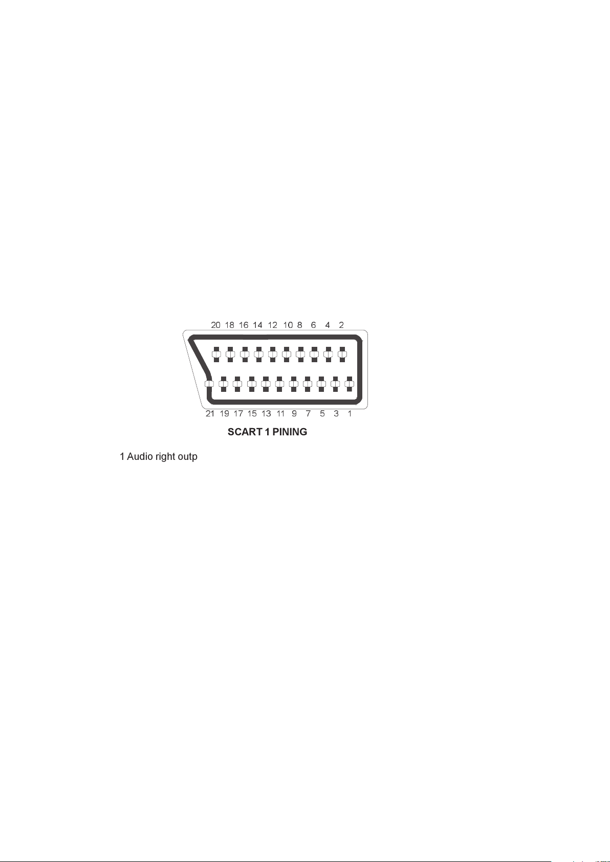
SCART 1 PINING
1 Audio right output 0.5Vrms / 1K
2 Audio right input 0.5Vrms / 10K
3 Audio left output 0.5Vrms / 1K
4 Ground AF
5 Ground Blue
6 Audio left input 0.5Vrms / 10K
7 Blue input 0.7Vpp / 75ohm
8 AV switching input 0-12VDC /10K
9 Ground Green
10 11 Green input 0.7Vpp / 75ohm
12 13 Ground Red
14 Ground Blanking
15 Red input 0.7Vpp / 75ohm
16 Blanking input 0-0.4VDC, 1-3VDC / 75 Ohm
17 Ground CVBS output
18 Ground CVBS input
19 CVBS output 1Vpp / 75ohm
20 CVBS input 1Vpp / 75ohm
21 Ground
1 INTRODUCTION
This is a 90° chassis capable of driving 14 tubes at the appropriate currents. The chassis is capable of operating in PAL,
SECAM and NTSC standards. The sound system is capable of giving 3 watts RMS output into a load of 16 ohms. One page and
US Closed Caption is also provided. The chassis is equipped with a 21 pin Eu-Scart connector.
Page 4

3
2 SMALL SIGNAL PART WITH STV2248:
STV2248 video processor is essential for realizing all small signal functions for a color TV receiver.
2.1 Vision IF Amplifier3
The vision IF amplifier can demodulate signals with positive and negative modulation. The PLL demodulator is completely
alignment-free. Although the VCO (Toko-coil) of the PLL circuit is external, yet the frequency is fixed to the required value
by the original manufacturer thus the Toko-coil does not need to be adjusted manually. The setting of the various
frequencies (38.9 or 45.75 MHz) can be made via changing the coil itself.
2.2 QSS Sound Circuit (QSS Versions)
The sound IF amplifier is similar to the vision IF amplifier and has an external AGC de-coupling capacitor. The single
reference QSS mixer is realised by a multiplier. In this multiplier the SIF signal is converted to the inter-carrier frequency
by mixing it with the regenerated picture carrier from the VCO. The mixer output signal is supplied to the output via a
high-pass filter for attenuation of the residual video signals. With this system a high performance hi-fi stereo sound
processing can be achieved. The AM sound demodulator is realised by a multiplier. The modulated sound IF signal is
multiplied in phase with the limited SIF signal. The demodulator output signal is supplied to the output via a low-pass filter
for attenuation of the carrier harmonics. The AM signal is supplied to the output via the volume control.
2.3. AM DEMODULATOR
The AM demodulated signal results from multiplying the input signal by itself, it is available on AM/FM output.
2.4 FM Demodulator and Audio Amplifier (Mono Versions):
The FM demodulator is realized as narrow-band PLL with external loop filter, which provides the necessary selectivity
without using an external band-pass filter. To obtain a good selectivity a linear phase detector and constant input signal
amplitude are required. For this reason the inter-carrier signal is internally supplied to the demodulator via a gain
controlled amplifier and AGC circuit. The nominal frequency of the demodulator is tuned to the required frequency (4.5/
5.5/6.0/6.5 MHz) by means of a calibration circuit that uses the clock frequency of the µ-controller/Teletext decoder as a
reference. The setting to the wanted frequency is realized by means of the software. It can be read whether the PLL
frequency is inside or outside the window and whether the PLL is in lock or not. With this information it is possible to
make an automatic search system for the incoming sound frequency. This is realized by means of a software loop that
alternate the demodulator to various frequencies, then select the frequency on which a lock condition has been found.
De-emphasis output signal amplitude is independent of the TV standard and has the same value for a frequency deviation
of ±25 kHz at the 4.5 MHz standard and for a deviation of ±50 kHz for the other standards. When the IF circuit is
switched to positive modulation the internal signal on de-emphasis pin is automatically muted. The audio control circuit
contains an audio switch and volume control. In the mono inter-carrier sound versions the Automatic Volume Leveling
(AVL) function can be activated. The pin to which the external capacitor has to be connected depends on the IC version.
For the 90° types the capacitor is connected to the EW output pin (pin 20). When the AVL is active it automatically
stabilizes the audio output signal to a certain level.
2.5 Video Switching
The video processor (STV2248C) has three CVBS inputs and two RGB inputs. The first CVBS input is used for external
CVBS from SCART 1, the second is used for either CVBS from FAV, and the third one is used for internal video. The
selection between both external video inputs signals is realized by means of software switches.
2.6 Synchronization Circuit
The video processor (STV224X) performs the horizontal and vertical processing. The external horizontal deflection circuit is
controlled via the Horizontal output pulse (HOUT). The vertical scanning is performed through an external ramp generator and
a vertical power amplifier IC controlled by the Vertical output pulse (VOUT).
The main components of the deflection circuit are:
PLL1: the first phase locked loop that locks the internal line frequency reference on the CVBS input signal. It is composed
of an integrated VCO (12 MHz) that requires the chroma Reference frequency (4.43MHz or 3.58MHz crystal oscillator
reference signal), a divider by 768, a line decoder, and a phase comparator.
PLL2: The second phase locked loop that controls the phase of the horizontal output
(Compensation of horizontal deflection transistor storage time variation). Also the horizontal position adjustment is also
performed in PLL2.
A vertical pulse extractor.
A vertical countdown system to generate all vertical windows (vertical synchronization window, frame blanking pulses, 50/
60Hz identification window...).
Automatic identification of 50/60Hz scanning.
PLL1 time constant control.
Noise detector, video identification circuits, and horizontal coincidence detector.
Vertical output stage including de-interlace function, vertical position control.
Vertical amplitude control voltage output (combined with chroma reference output and Xtal 1 indication).
Page 5

4
2.7 Chroma and Luminance Processing:
The chroma decoder is able to demodulate PAL, NTSC and SECAM signals.
The decoder dedicated to PAL and NTSC sub-carrier is based on a synchronous demodulator,
and an Xtal PLL locked on the phase reference signal (burst).
The SECAM demodulation is based on a PLL with automatic calibration loop.
The color standard identification is based on the burst recognition.
Automatic and forced modes can be selected through the I2C bus.
NTSC tint, and auto flesh are controlled through I2C bus.
Xtal PLL can handle up to 3 crystals to work in PAL M, PAL N and NTSC M for South America.
ACC an ACC overload control the chroma sub-carrier amplitude within 26dB range. Both
ACC s are based on digital systems and do not need external capacitor.
All chroma filters are fully integrated and tuned via a PLL locked on Xtal VCO signal.
A second PLL is used for accurate fine-tuning of the SECAM bell filter. This tuning is achieved during the frame blanking.
An external capacitor memorizes the bell filter tuning voltage.
A base-band chroma delay-line rebuilds the missing color line in SECAM and removes transmission phase errors in PAL.
The base-band chroma delay line is clocked with 6MHz signal provided by the horizontal scanning VCO.
The luminance processor is composed of a chroma trap filter, a luminance delay line, a peaking function with noise coring
feature, a black stretch circuit.
Trap filter and luminance delay lines are achieved with the use of bi-quad integrated filters, auto-aligned via a master filter
phase locked loop.
2.8 RGB output circuit:
The video processor performs the R, G, B processing.
There are three sources:
1. Y,U,V inputs (coming from luma part (Y output), and chroma decoder outputs (R-Y, B-Y outputs).
2. External R,G,B inputs from SCART (converted internally in Y,U,V), with also the possibility to input YUV signals from a
DVD player, (YUV specification is Y=0.7 V PP , U= 0.7 V PP , V = 0.7V PP for 100% color bar).
3. Internal R,G,B inputs (for OSD and Teletext display)
The main functions of the video part are:
- Y,U,V inputs with integrated clamp loop, allowing a DC link with YUV outputs,
- External RGB inputs (RGB to YUV conversion), or direct YUV inputs,
- Y,U,V switches,
- Contrast, saturation, brightness controls,
- YUV to RGB matrix,
- OSD RGB input stages (with contrast control),
- RGB switches,
- APR function,
- DC adjustment of red and green channels,
- Drive adjustments (R, G, B gain),
- Digital automatic cut-off loop control,
- Manual cut-off capability with I2C adjustments,
- Half tone, oversize blanking, external insertion detection, blue screen,
- Blanking control and RGB output stages.
2.9 µ-Controller
The ST92195 is the micro-controller, which is required for a color TV receiver. ST92195D1 is the version with one page
Teletext . The IC has the supply voltages of 5 V and they are mounted in PSDIP package with 56 pins.
µ-Controller has the following features
Display of the program number, channel number, TV Standard, analogue values, sleep timer, parental control and mute
is done by OSD
Single LED for standby and on mode indication
System configuration with service mode
3 level logic output for SECAM and Tuner band switching
Page 6
5
3 TUNER
Either a PLL or a VST tuner is used as a tuner.
UV1316 (VHF/UHF) is used as a PLL tuner. For only PALM/N, NTSC M applications UV 1336 is used as the PLL tuner. UV
1315 (VHF/UHF) is used as a VST Tuner.
Channel coverage of UV1316:
!"#
!!"#$%&'(#))*+, '#-+*&'(#))*+,
'(#))*+,'(#))*+,
+./&-012&&&&&&&&&&*3&4.&'&&&&&&&&&&&56738&4.&63738&9:;&&&&&&&&,<:&4.&,<6&&&&&&=>738&4.&:85738
?@2&-012&&&&&&&&&*8&4.&*:3&&&&&&&&&:A8738&4.&335738&&&&&&&&&,<>&4.&,B6&&&&&:=:738&4.&5B>738
(@CD&-012&&&&&&&*3:&4.&*=>&&&&&&&5A:738&4.&688738&93;&&&&,B>&4.&,5:&&&&&55A738&4.&5=B738
!%*EF*)'G
%#)H*&9?(I;
!%*EF*)'G
%#)H*&9?(I;
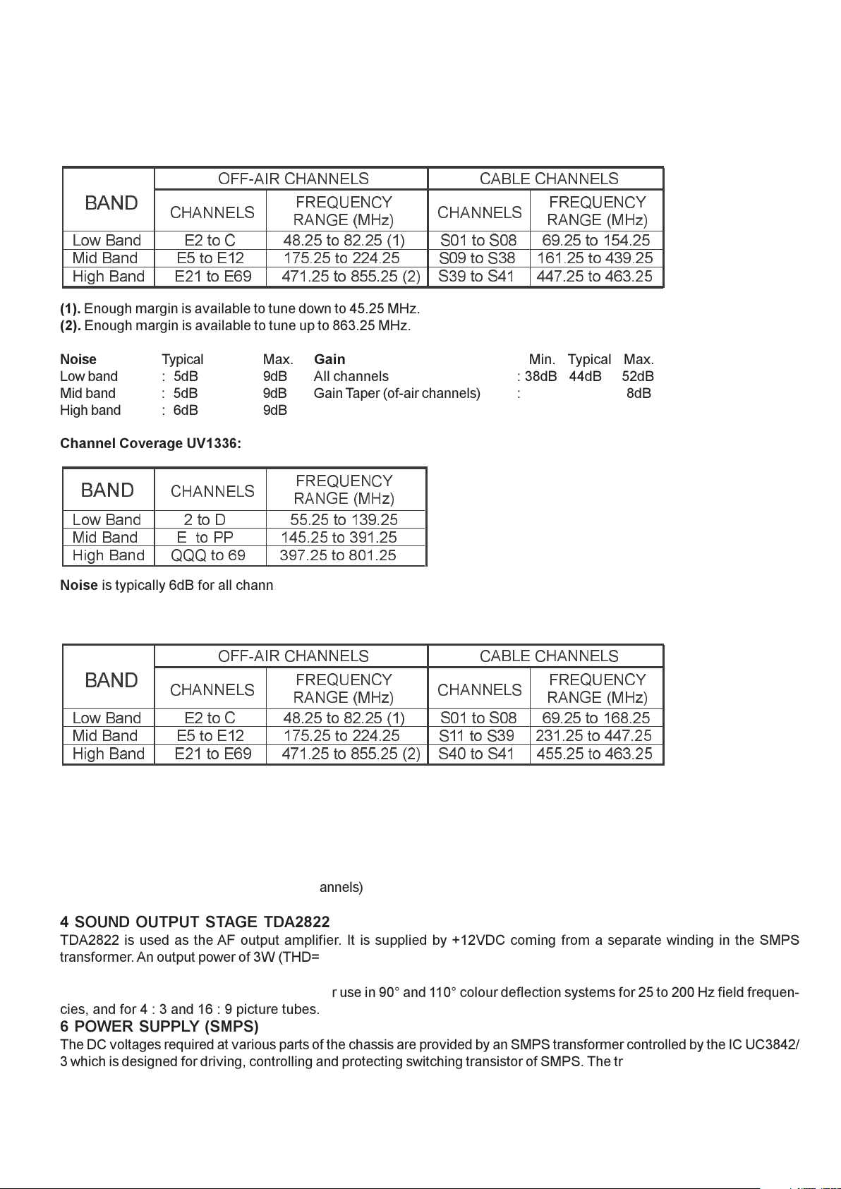
(1). Enough margin is available to tune down to 45.25 MHz.
(2). Enough margin is available to tune up to 863.25 MHz.
Noise Typical Max. Gain Min. Typical Max.
Low band : 5dB 9dB All channels : 38dB 44dB 52dB
Mid band : 5dB 9dB Gain Taper (of-air channels) : 8dB
High band : 6dB 9dB
Channel Coverage UV1336:
!"#
!"##$%&
%'()*+,-)))))))))).)/')0)))))))))))))))112.1)/')3452.1
67-)*+,-)))))))))$))/')88)))))))))))3912.1)/')4532.1
!7:;)*+,-))))))<<<)/')=5))))))))45>2.1)/')?@32.1
AB$<C$# D
B"#E$)F6!GH
Noise is typically 6dB for all channels. Gain is minimum 38dB and maximum 50dB for all channels.
Channel Coverage of UV1315:
!"#
!!"#$%&'(#))*+, '#-+*&'(#))*+,
'(#))*+,'(#))*+,
+./&-012&&&&&&&&&&*3&4.&'&&&&&&&&&&&56738&4.&63738&9:;&&&&&&&&,<:&4.&,<6&&&&&&=>738&4.&:=6738
?@2&-012&&&&&&&&&*8&4.&*:3&&&&&&&&&:A8738&4.&335738&&&&&&&&&,::&4.&,B>&&&&&3B:738&4.&55A738
(@CD&-012&&&&&&&*3:&4.&*=>&&&&&&&5A:738&4.&688738&93;&&&&,5<&4.&,5:&&&&&588738&4.&5=B738
!%*EF*)'G
%#)H*&9?(I;
!%*EF*)'G
%#)H*&9?(I;
(1). Enough margin is available to tune down to 45.25 MHz.
(2). Enough margin is available to tune up to 863.25 MHz.
Noise Typ. Max. Gain Min. Typ. Max.
Low band 6dB 9dB All Channels 38dB 44dB 50dB
Mid band 6dB 10dB Gain Taper 8dB
High band 6dB 11dB (off-air channels)
4 SOUND OUTPUT STAGE TDA2822
TDA2822 is used as the AF output amplifier. It is supplied by +12VDC coming from a separate winding in the SMPS
transformer. An output power of 3W (THD=10%) can be delivered into an 16 ohm load.
5 VERTICAL OUTPUT STAGE WITH TDA8174A
The TDA8174A is a power amplifier circuit for use in 90° and 110° colour deflection systems for 25 to 200 Hz field frequencies, and for 4 : 3 and 16 : 9 picture tubes.
6 POWER SUPPLY (SMPS)
The DC voltages required at various parts of the chassis are provided by an SMPS transformer controlled by the IC UC3842/
3 which is designed for driving, controlling and protecting switching transistor of SMPS. The transformer produces 115V for
FBT input, ±12V for audio output IC, S+5V and 8V for ST92195.
7 DISCRETE VIDEO AMPLIFIER
Three high voltage, high frequency transistor is used for RGB amplifier. This application works on fixed AC and DC gains.
Page 7

6
8 SERIAL ACCESS CMOS 8K EEPROM 24C08
The 24C08 is a 8Kbit electrically erasable programmable memory (EEPROM), organized as 4 blocks of 256*08 bits. The
memory is compatible with the I²C standard, two wire serial interface which uses a bi-directional data bus and serial clock.
9 SAW FILTERS
Saw filter type : Model:
G1975M : PAL B/G MONO
K2966M : PAL SECAM B/G/D/K/I MONO
J1981 : PAL-I MONO
K2966M : PAL-SECAM B/G/D/K/I/I MONO
K2962M : PAL-SECAM B/G/D/K/I/L/L MONO
L9653 : Secam L/L audio
M1962M : PAL M/N NTSC M MONO
IC DESCRIPTIONS AND INTERNAL BLOCK DIAGRAM
· ST92195
· STV224X
· TUNER (UV1315, UV1316, UV1336)
· TDA2822
· TDA8174A
· UC3842/3
· 24C08
· SAW FILTERS
G1975M, K2966M, K2962M, M1962M
10.1 ST92195
The ST92195 is a member of the ST9+ family of micro-controllers, completely developed and produced by SGS-THOMSON
Microelectronics using a proprietary n-well HCMOS process. The nucleus of the ST92195 is the advanced Core, which
includes the Central Processing Unit (CPU), the ALU, the Register File and the interrupt controller. The Core has
independent memory and register buses to add to the efficiency of the code. A set of on-chip peripherals form a complete
sys-tem for TV set and VCR applications:
· Voltage Synthesis
· VPS/WSS Slicer
· Teletext Slicer
· Teletext Display RAM
· OSD
Additional peripherals include a watchdog timer, a serial peripheral interface (SPI), a 16-bit timer and an A/D converter.
Page 8
7
!"#$%! &!'(%)*#)+,
!"#$#"%! ! &'"(#)*+),'"-./"(012
&'"(#)*+.,3"(013
&'"(#)*+),'"-./"(014
&'"(#)*+),'"-./"(015
&'"(#)*+),'"6-/"(017
&'"(#)*+),'"6-/"(018
!"#$#"%! !
+"9"%! !
+"9"%! !":"(#;
<"9"%! !:(#;:0((
+"9"%! !:(#;:29(:0((
!"#$%&#''(&)*(&+,#$)%-.'(
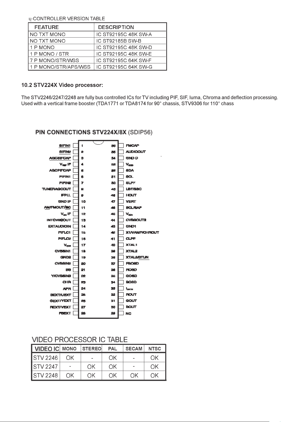
10.2 STV224X Video processor:
The STV2246/2247/2248 are fully bus controlled ICs for TV including PIF, SIF, luma, Chroma and deflection processing.
Used with a vertical frame booster (TDA1771 or TDA8174 for 90° chassis, STV9306 for 110° chassis), they allow the
design of multi-standard (BGDKIMNLL, PAL/ SECAM/NTSC) sets with very few external components and no manual
adjustments.
!"#$$%&
!"#$$%'
!"#$$%()*)*
+
+
)*
)*)* )*
)*)* )* )*
+
+
)*
!"#$%!&
!"! #$%&%! '() #%*( "$#*
!"#$%&'$(#))$'%!(%*+,-#
Page 9
8
10.3 UV1315, UV1316, UV1336
General description of UV1315:
The UV1315 tuner belongs to the UV 1300 family of tuners, which are designed to meet a wide range of applications. It is a
combined VHF, UHF tuner suitable for CCIR systems B/G, H, L, L, I and I.
Features of UV1315:
· Member of the UV1300 family small sized UHF/VHF tuners
· Systems CCIR:B/G, H, L, L, I and I; OIRT:D/K
· Voltage synthesized tuning (VST)
· Off-air channels, S-cable channels and Hyper-band
· Standardized mechanical dimensions and pinning
PINNING PIN VALUE
1. Gain control voltage (AGC) : 4.0V, Max:4.5V
2. Tuning voltage
3. High band switch : 5V, Min:4.75V, Max:5.5V
4. Mid band switch : 5V, Min:4.75V, Max:5.5V
5. Low band switch : 5V, Min:4.75V, Max:5.5V
6. Supply voltage : 5V, Min:4.75V, Max:5.5V
7. Not connected
8. Not connected
9. Not connected
10.Symmetrical IF output 1
11. Symmetrical IF output 2
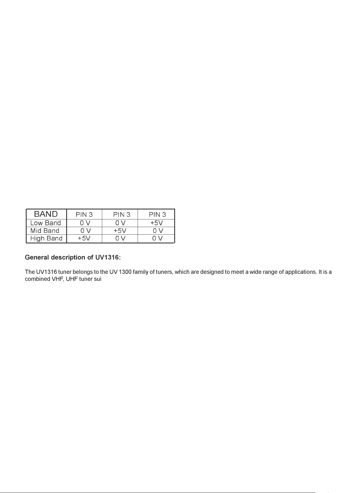
Band switching table:
!"#
!"#$ !"#$ !"#$
%&'#()*+##########,#-#############,#-#############./-
01+#()*+###########,#-############./-##############,#-
2134#()*+########./-#############,#-##############,#-
General description of UV1316:
The UV1316 tuner belongs to the UV 1300 family of tuners, which are designed to meet a wide range of applications. It is a
combined VHF, UHF tuner suitable for CCIR systems B/G, H, L, L, I and I.
Features of UV1316:
· Member of the UV1300 family small sized UHF/VHF tuners
· Systems CCIR: B/G, H, L, L, I and I; OIRT: D/K
· Digitally controlled (PLL) tuning via I²C-bus
· Off-air channels, S-cable channels and Hyper-band
· World standardized mechanical dimensions and world standard pinning
· Complies to CENELEC EN55020 and EN55013
PINNING PIN VALUE
1. Gain control voltage (AGC) : 4.0V, Max:4.5V
2. Tuning voltage
3. I²C-bus address select : Max:5.5V
4. I²C-bus serial clock : Min:-0.3V, Max:5.5V
5. I²C-bus serial data : Min:-0.3V, Max:5.5V
6. Not connected
7. PLL supply voltage : 5.0V, Min:4.75V, Max:5.5V
8. ADC input
9. Tuner supply voltage : 33V, Min:30V, Max:35V
10. Symmetrical IF output 1
11. Symmetrical IF output 2
Page 10

9
General description of UV1336:
UV1336 series is developed for reception of channels broadcast in accordance with the M, N standard.
Features of UV1336:
· Global standard pinning
· Integrated Mixer-Oscillator & PLL function
· Conforms to CISPR 13, FCC and DOC (Canada) regulations
· Low power consumption
· Both Phono connector and F connector are available
PINNING PIN VALUE
1. Gain control voltage : 4.0V, Max:4.5V
2. Tuning voltage
3. Address select Max :5.5V
4. Serial cloc : Min :-0.3V, Max:5.5V
5. Serial data : Min :-0.3V, Max:5.5V
6. Not connected
7. Supply voltage : 5.0V, Min:4.75V, Max:5.5V
8. ADC input (optional)
9. Tuning supply voltage : 33V, Min:30V, Max:35V
10. Ground
11. IF output
10.4 TDA2822
General Description of TDA2822
The TDA2822 is a mono bridge amplifier specially designed for TV and Portable Radio applications. Requires very few
external components
WIDE SUPPLY VOLTAGE RANGE (3-15V)
MINIMUM EXTERNAL COMPONENTS
NO SVR CAPACITOR
NO BOOTSTRAP
NO BOUCHEROT CELLS
SHORT CIRCUIT PROTECTION
THERMAL OVERLOAD PROTECTION
PINNING
1. Output 1
2. Vcc
3. Output 2
4. Gnd
5. Input 2 (-)
6. Input 2 (+)
7. Input 1 (+)
8. Input 1 (-)
10.5 TDA8174AW
INDEPENDENT VERTICAL AMPLITUDE ADJUSTEMENT. BUFFER STAGE. POWER AMPLIFIER
FLYBACKGENERATOR. THERMALPROTECTION .INTERNAL REFERENCE VOLTAGE DECOU-PLING
General Description:
TDA8174Aand TDA8174AWare a monolithic integrated circuits. It is a full performance and very efficient vertical deflection
circuit intended for direct drive of a TV picture tube in Color and B & W television as well as in Monitor and Data displays.
PINNING
1. POWER OUTPUT
2. OUTPUT STAGE Vs
3. TRIGGER INPUT
4. HEIGHT ADJUSTMENT
5. VOLTAGE REF DECOUPLING
6. GROUND
7. RAMP GENERATOR
8. BUFFER OUTPUT
9. INVERTING INPUT
10. Vs
11. FLYBACK GENERATOR
Page 11

10
10.6 UC3842/3
General description:
DESCRIPTION
TheUC3842/3/4/5family of control ICs provides the necessary features to implement off-line or DC to DC fixed frequency
current mode control schemes With a minimal external parts count. Internally implemented circuits include under voltage
lockout featuring start-up current less than 1 mA, a precision reference trimmed for accuracy at the error amp input, logic to
insure latched operation, a PWM comparator which also provides current limit control, and a totem pole output stage
designed to source or sink high peak current. The output stage, suitable for driving N-Channel MOSFETs, is low in the offstate. Differences between members of this family are the under-voltage lockout thresholds and maximum duty cycle
ranges. The UC3842 and UC3844 have UVLO thresholds of 16V (on) and 10V (off), ideally suited off-line applications The
corresponding thresholds for the UC3843 and UC3845 are 8.5 V and 7.9 V. The UC3842 and UC3843 can operate to duty
cycles approaching 100%. A range of the zero to < 50 % is obtained by the UC3844 and UC3845by the addition of an internal
toggle flip flop which blanks the output off every other clock cycle.
General Features
OPTIMIZED FOR OFF-LINE AND DC TO DC
CONVERTERS
LOWSTART-UP CURRENT (< 1 mA)
AUTOMATIC FEED FORWARD COMPENSA-TION
PULSE-BY-PULSECURRENT LIMITING
ENHANCED LOAD RESPONSE CHARAC-TERISTICS
UNDER-VOLTAGELOCKOUTWITHHYSTER-ESIS
DOUBLE PULSE SUPPRESSION
HIGH CURRENT TOTEMPOLE OUTPUT
INTERNALLY TRIMMED BANDGAP REFER-ENCE
500 KHz OPERATION
LOWRO ERRORAMP
PINNING PIN VALUE
1. Comp Compensation input
2. Vfb Error amplifier input (Regulation)
3. I Sense Over current protection voltage 1V typ.
4. Rt/Ct Timing network
5. Ground
6. Output MOSFET driver
7. Vcc Supply voltage
8. Vref +5V Reference output
10.7 E²Eprom 24CO8
General description:
The 24C08 is a 8Kbit electrically erasable programmable memory (EEPROM), organized as 4 blocks of 256 * 08 bits. The
memory operates with a power supply value as low as 2.5V.
Features:
Minimum 1 million ERASE/WRITE cycles with over 10 years data retention
Single supply voltage:4.5 to 5.5V
Two wire serial interface, fully I²C-bus compatible
Byte and Multi-byte write (up to 8 bytes)
Page write (up to 16 bytes)
Byte, random and sequential read modes
Self timed programming cycle
PINNING PIN VALUE
1. Write protect enable : 0V
2. Not connected : 0V
3. Chip enable input : 0V
4. Ground : 0V
5. Serial data address input/output : Input LOW voltage : Min : -0.3V, Max : 0.3*Vcc
: Input HIGH voltage : Min : 0.7*Vcc, Max : Vcc+1
6. Serial clock : Input LOW voltage : Min : -0.3V, Max : 0.3*Vcc
: Input HIGH voltage : Min : 0.7*Vcc, Max : Vcc+1
7. Multibyte/Page write mode : Input LOW voltage : Min : -0.3V, Max : 0.5V
: Input HIGH voltage : Min : Vcc-0.5, Max : Vcc+1
8. Supply voltage : Min :2.5V, Max : 5.5V
Page 12

11
Saw filters list:
K2962/K2966
!
"
!
!"#$"%&"&'"("('
&)*+),
""""""""""""(*+-.
!"#$"%&"&'"/"/'
&)*++,
0("/"/'
12*32
!"#$"%&
&)*++,
0("#$
$2*4-,
!"#$ %&"!$
PINNING
1. Input
2. Input-ground
3. Chip carrier-ground
4. Output
5. Output
L9653M
PINNING
1. Input
2. Switching Input
3. Chip carrier-ground
4. Output
5. Output
Page 13

12
!"
!
!
!"
!"
#$%&'
(
)*+,$ ,-*
../
!
0.1!+'2(3
0.1
!
,"&
,
2
4
56718
5
!"##$%
&
"'()*
+,*&) *,
!-#.-/
0'&,*
&*1!,*22)
,
"#$
%&'
(
%)(
%&'
(
!"#$##
!%&'())*+",-.
!"$/01"2
*+"
%&'
(
9:;
!"#$!%&'
(
)"#*+
,-./.)0
*#)+!
12#&3 #%453#"3-#&
1
13'"&
6
0'*
!!"#$%&%'()*
'#+,+-&"&+,+.
Page 14

13
TITANIUM TELETEXT Languages Groups
GROUP 1 - WEST
ENGLISH
FRENCH
SWEDISH
CZECH
GERMAN
PORTUGUESE
ITALIAN
RUMANIAN
GROUP 2 WEST / EAST
POLISH
FRENCH
SWEDISH
CZECH
GERMAN
SERBIAN
ITALIAN
RUMANIAN
GROUP 3 WEST / TURKEY
ENGLISH
FRENCH
SWEDISH
TURKISH
GERMAN
PORTUGUESE
ITALIAN
RUMANIAN
GROUP 4 EAST / CYRILLIC
ENGLISH
CYRILLIC
SWEDISH
CZECH
GERMAN
SERBIAN
LETTISH
RUMANIAN
GROUP 5 - ARABIC
ENGLISH
FRENCH
SWEDISH
TURKISH
GERMAN
HEBREW
ITALIAN
ARABIC
Using Coloured Buttons
RED : No function.
GREEN : Is used to switch the aspect ratio between 4:3 and 16:9.
YELLOW : Is used to prepare the system for screen-adjustments.
BLUE : No function.
Page 15

14
CHASSIS MANUAL ADJUSTMENT PROCEDURE
In order to enter service menu, first enter the main menu and then press the digits 4, 7, 2 and 5 respectively.
To select adjust parameters, use or buttons. To change the selected parameter, use or buttons.
Selected parameter will be highlighted.
Entire service menu parameters of CHASSIS are listed below. For some of parameters the default values are
given on the same table.
REGISTER PARAMETER NOTE (NUMBERS ARE DEFAULT VALUES FOR CONCERNED PARAMETER)
OSD OSD Horizontal Position ADJUST HORIZONTAL POSITION FOR OSD
IF1 IF Coarse Adjust IF1 Adjust Course Neg. Adj. (WO / L)
IF2 IF Fine Adjust IF2 Adjust Fine Neg. Adj. (WO / L)
IF3 IF Coarse Adjust for L-Prime IF3 Adjust Course Pos. Adj. (W / L)
IF4 IF Fine Adjust for L-Prime IF4 Adjust Fine Pos. Adj. (W / L)
AGC Automatic Gain Control AGC Adjust AGC
VLIN Vertical Linearity ADJUST VERTICAL LINEARITY
VS1A Vertical Size for 50 Hz / 4:3 ADJUST VERTICAL SIZE FOR 4:3 MODE (50 HZ)
VS1B Vertical Size for 50 Hz / 16:9 ADJUST VERTICAL SIZE FOR 16:9 MODE (50 HZ)
VP1 Vertical Position for 50 Hz ADJUST VERTICAL POSITION (50 HZ)
HP1 Horizontal Position for 50 Hz ADJUST HORIZONTAL POSITION (50 HZ)
VS2A Vertical Size for 60 Hz / 4:3 ADJUST VERTICAL SIZE FOR 4:3 MODE (60 HZ)
VS2B Vertical Size for 60 Hz / 16:9 ADJUST VERTICAL SIZE FOR 16:9 MODE (60 HZ)
VP2 Vertical Position for 60 Hz ADJUST VERTICAL POSITION (60 HZ)
HP2 Horizontal Position for 60 Hz ADJUST HORIZONTAL POSITION (60 HZ)
RGBH RGB Horizontal Shift Offset CVBS RGB HORIZONTA L POSITION COMPENSATION
WR White Point Adjust for RED 40
WG White Point Adjust for GREEN 40
WB White Point Adjust for BLUE 40
BR Bias for RED 31
BG Bias for GREEN 31
APR APR Threshold 10
FMP1 FM Prescaler when AVL is OFF 9 (STEREO ONLY)
NIP1 NICAM Prescaler when AVL is OFF 20 (STEREO ONLY)
SCP1 SCART Prescaler when AVL is OFF 13 (STEREO ONLY)
FMP2 FM Prescaler when AVL is ON 13 (STEREO ONLY)
NIP2 NICAM Prescaler when AVL is ON 16 (STEREO ONLY)
SCP2 SCART Prescaler when AVL is ON 13 (STEREO ONLY)
F1H High Byte of crossover frequency for VHF1-VHF3 MEANINGFUL FOR ONLY PLL TUNER (see tuner setting table)
F1L Low Byte of crossover frequency for VHF1-VHF3 MEANINGFUL FOR ONLY PLL TUNER (see tuner setting table)
F2H High Byte of crossover frequency for VHF3-UHF MEANINGFUL FOR ONLY PLL TUNER (see tuner setting table)
F2L Low Byte of crossover frequency for VHF3-UHF MEANINGFUL FOR ONLY PLL TUNER (see tuner setting table)
BS1 Band Switch Byte for VHF1 Meaningful for only MEANINGFUL FOR ONLY PLL TUNER (see tuner setting table)
BS2 Band Switch Byte for VHF3 Meaningful for only MEANINGFUL FOR ONLY PLL TUNER (see tuner setting table)
BS3 Band Switch Byte for UHF Meaningful for only MEANINGFUL FOR ONLY PLL TUNER (see tuner setting table)
CB Control Byte Meaningful for only PLL Tuner MEANINGFUL FOR ONLY PLL TUNER (see tuner setting table)
OP1 Option 1 (see the Option List) PERIPHERAL OPTIONS (see option table)
OP2 Option 2 (see the Option List) RECEPTION STANDART OPTIONS (see option table)
OP3 Option 3 (see the Option List) VIDEO OPTIONS (see option table)
OP4 Option 4 (see the Option List) TV FEATURE OPTIONS (see option table)
OP5 Option 5 (see the Option List) CHANNEL TABLE OPTIONS (see option table)
TX1 Teletext Option 1 (see the Option List) TELETEXT OPTIONS (see option table)
Page 16

15
USING COLOUR BUTTONS ON SERVICE MENU
RED BUTTON (For Stereo models only): It switches the AVL to ON or OFF mode on service menu. AVL word is visible on
service menu when AVL is on.
GREEN BUTTON : It switched the PICTURE MODE to 4:3 or 16:9 on service menu. It is usefull when it is necessary to
adjust 16:9 picture mode vertical size.
YELLOW BUTTON : It switches to VERTICAL SCAN DISABLE mode. It is usefull to adjust screen voltage.
BLUE BUTTON : It is used to adjust AGC and IF automatically on service menu.
WHITE BALANCE ADJUSTMENT
The following three parameters are used to make white balance adjustment. To do this, use a Colour Analyser. Using WR
(White point adjust for RED), WG (White point adjust for GREEN), WB (White point adjust for BLUE) parameters, insert
the + sign in the square which is in the middle of the screen.
The suggested values for these parameters are given on the table above.
AGC ADJUSTMENT
In order to do AGC adjustment, enter a
60dBmV RF signal level from channel C-12 (224.25 MHz)
Select AGC parameter from service menu. Press BLUE (INSTALL) button from remote controller. The adjustment will be
done automatically by software. See the AGC indicator on service menu, it must be 1. Check that picture is normal at
90dBmV signal level.
! !
"#$"%&"'()*+ (,'$"%&"'()*+ %*%-
IF NEGATIVE ADJUSTMENT (WITHOUT L SYSTEMS)
Set the video pattern to a PAL colour bar pattern with frequency 38.9 MHz. Apply this IF signal to PIN-10 and PIN-11
of tuner. Press PROG-1 and after that BLUE (INSTALL)button from remote controller. Select the standart as BG or I.
(if BG is not available) Enter service menu. Select IF1 parameter from service menu and press BLUE (INSTALL) button
from remote controller. IF adjustment will be done automatically by software. See the IF indicator on service menu, it
must be like on FIGURE-1 shown above.
IF POSITIVE ADJUSTMENT (WITH L SYSTEMS)
Set the video pattern to a SECAM-L colour bar pattern with frequency 33.9 MHz. Apply this IF signal to PIN-10 and
PIN-11 of tuner. Press PROG-1 and after that BLUE (INSTALL)button from remote controller. Select the BAND VHF-1
(C1 C4 for PLL tuners) and standart as L(L for PLL Tuner). Enter service menu. Select IF1 parameter from service menu
and press BLUE (INSTALL) button from remote controller. IF adjustment will be done automatically by software. See the IF
indicator on service menu, it must be like on FIGURE-1 shown above.
OSD HORIZONTAL POSITION ADJUSTMENT
Select OSD parameter on service menu. Adjust the horizontal position of OSD to the middle of screen, by using the
reference bar on bottom of service menu. (OSD adjust also Horizontal position for text screen)
TELETEXT BRIGHTNESS ADJUSTMENT
Set the TV set to a channel with TeleText. Enter service menu. Press TEXT button from remote controller. Adjust
BRIGHTNESS parameter to value 30 by using left-right buttons from remote controller. Press TV button and MENU button
from remote controller respectively. Adjustment is done.
Page 17

16
!"#$%&'()$*!&"#+(, )-./
!"#$%&'(0$1!(, 023/
!"#$%&'(0$1!(, 024/
!"#$%&'(567$#$6*(, 52/
86"$16*#&'(567$#$6*(,852/
!"#$%&'(0$1!(, 093/
!"#$%&'(0$1!(, 094/
!"#$%&'(567$#$6*(, 59/
86"$16*#&'(567$#$6*(,859/
:;4(<=>?(86"$16*#&'(567$#$6*(,:;48/
!"#$%&%'()%*+,%-.$-/#%"#0"%1&""#$!%2.&%345%67&!8#%9):;%".//%<=>%0##%-.$-/#%&0%$=>!?%&0%1=00.@/#5
!"#$%&%'()%*+,%-.$-/#%"#0"%1&""#$!%2.&%345%67&!8#%9AB(%C9#$".-&/%A.D#E%".//%7=$.D=!"&/%@/&-F%/.!#0%=!%@="7%"7#%>11#$%&!?%/=G#$
1&$"%=H%"7#%"#0"%1&""#$!%@#-=I#%2#$<%-/=0#%"=%"7#%>11#$%&!?%/=G#$%7=$.D=!"&/%0.?#0%=H%1.-">$#%">@#%&!?%!#&$/<%&@=>"%"=%?.0&11#&$5
67#-F%&!?%$#&?J>0"%9#$".-&/%A.D#%."#I%.H%"7#%&?J>0"I#!"%@#-=I#0%.I1$=1#$%&H"#$%0=I#%="7#$%8#=I#"$.-%&?J>0"I#!"0%&$#%?=!#5
!"#$%&%'()%*+,%-.$-/#%"#0"%1&""#$!%2.&%345% !"#$%0#$2.-#%I#!>%&!?%1$#00%,3 ;%C':6KL3 E%@>""=!%H$=I%$#I="#%-=!"$=//#$%"=
0G."-7%"=%BMNO%1.-">$#%I=?#%=!%0#$2.-#%I#!>5%67&!8#%9AB*%C9#$".-&/%A.D#E%".//%"7#%1.-">$#%@#-=I#0%BMNO%H=$I&"5%67#-F%&!?%
#&?J>0"%9#$".-&/%A.D#%."#I%.H%"7#%&?J>0"I#!"%@#-=I#0%.I1$=1#$%&H"#$%0=I#%="7#$%8#=I#"$.-%&?J>0"I#!"0%&$#%?=!#5
!"#$
%&%'()%*+,%-.$-/#%"#0"%1&""#$!%2.&%345%67&!8#%9#$".-&/%'=0.".=!%".//%"7#%"#0"%1&""#$!%.0%2#$".-&//<%-#!"$#?5%P=$.D=!"&/%/.!#%&"%"7#
-#!"$#%1&""#$!%.0%.!%#Q>&/%?.0"&!-#%@="7%"=%>11#$%&!?%/=G#$%0.?#%=H%"7#%1.-">$#%">@#5%67#-F%&!?%$#&?J>0"%9#$".-&/%'=0.".=!%."#I%.H%
"7#%&?J>0"I#!"%@#-=I#0%.I1$=1#$%&H"#$%0=I#%="7#$%8#=I#"$.-%&?J>0"I#!"0%&$#%?=!#5
!"#$%&%'()%*+,%-.$-/#%"#0"%1&""#$!%2.&%345%67&!8#%P=$.D=!"&/%'=0.".=!%".//%"7#%1.-">$#%.0%7=$.D=!"&//<%-#!"$#?5%67#-F%&!?%$#&?J>0"
P=$.D=!"&/%'=0.".=!%."#I%.H%"7#%&?J>0"I#!"%@#-=I#0%.I1$=1#$%&H"#$%0=I#%="7#$%8#=I#"$.-%&?J>0"I#!"0%&$#%?=!#5
!"#$%&%;KA6RS%-.$-/#%"#0"%1&""#$!%2.&%34%=$%2.?#=%.!1>"05%67&!8#%9#$".-&/%A.D#%".//%"7#%-7#-F#$#?%%1&$"0%=H%"#0"%1&""#$!%=!%@="7%=H
>11#$%&!?%/=G#$%0.?#%?.00&11#&$5%67#-F%&!?%$#&?J>0"%9#$".-&/%A.D#%."#I%.H%"7#%&?J>0"I#!"%@#-=I#0%.I1$=1#$%&H"#$%0=I#%="7#$
8#=I#"$.-%&?J>0"I#!"0%&$#%?=!#5
!"#$%&%;KA6RS%-.$-/#%"#0"%1&""#$!%2.&%34%=$%2.?#=%.!1>"05% !"#$%0#$2.-#%I#!>%&!?%1$#00%,3 ;%C':6KL3 E%@>""=!%H$=I%$#I="#
-=!"$=//#$
%"=%0G."-7%"=%BMNO%1.-">$#%I=?#%=!%0#$2.-#%I#!>5%67&!8#%9#$".-&/%A.D#%".//%"7#%1.-">$#%@#-=I#0%BMNO%H=$I&"5%67#-F%&!?%$#&?J>0"
9#$".-&/%A.D#%."#I%.H%"7#%&?J>0"I#!"%@#-=I#0%.I1$=1#$%&H"#$%0=I#%="7#$%8#=I#"$.-%&?J>0"I#!"0%&$#%?=!#5
!"#$%&%;KA6RS%-.$-/#%"#0"%1&""#$!%2.&%34%=$%2.?#=%.!1>"05%67&!8#%9#$".-&/%'=0.".=!%".//%"7#%"#0"%1&""#$!%.0%2#$".-&//<%-#!"$#?5
P=$.D=!"&/%/.!#%&"%"7#%-#!"$#%1&""#$!%.0%.!%#Q>&/%?.0"&!-#%@="7%"=%>11#$%&!?%/=G#$%0.?#%=H%"7#%1.-">$#%">@#5%67#-F%&!?%$#&?J>0"
9#$".-&/%'=0.".=!%."#I%.H%"7#%&?J>0"I#!"%@#-=I#0%.I1$=1#$%&H"#$%0=I#%="7#$%8#=I#"$.-%&?J>0"I#!"0%&$#%?=!#5
!"#$%&%;KA6RS%-.$-/#%"#0"%1&""#$!%2.&%34%=$%2.?#=%.!1>"05%67&!8#%P=$.D=!"&/%'=0.".=!%".//%"7#%1.-">$#%.0%7=$.D=!"&//<%-#!"$#?5
67#-F%&!?%$#&?J>0"%9#$".-&/%A.D#%."#I%.H%"7#%&?J>0"I#!"%@#-=I#0%.I1$=1#$%&H"#$%0=I#%="7#$%8#=I#"$.-%&?J>0"I#!"0%&$#%?=!#5
!"#$%&%3,*%-.$-/#%"#0"%1&""#$!%2.&%2.?#=%.!1>"05%4=$-#%"7#%K9%"=%3,*%I=?#%@<%1$#00.!8%(9%@>""=!%H$=I%$#I="#%-=!"$=//#$5
67&!8#%3,*%P=$.D=!"&/%'=0.".=!%".//%"7#%1.-">$#%.0%7=$.D=!"&//<%-#!"$#?5%67#-F%&!?%$#&?J>0"%3,*P%."#I%.H%"7#%&?J>0"I#!"%@#-=I#0
.I1$=1#$%&H"#$%0=I#%="7#$%8#=I#"$.-%&?J>0"I#!"0%&$#%?=!#5
!
"
#
$
"
%
&
'
(
)
"
*
+
)
'
,
-
.
/
"
0
1
2
,
(
'
3
.
&
'
(
4
!
"
#
$
"
%
*
0
5
"
*
+
)
'
,
-
.
/
"
0
1
2
,
(
'
3
.
&
'
(
50 Hz. 4:3 Geometry Adjustment 60 Hz. 4:3 Geometry Adjustment
50 Hz. 16:9 Geometry Adjustment 60 Hz. 16:9 Geometry Adjustment
Page 18

17
OPTION SETTINGS
Select concerned OPTION from service menu. To change a bit on selected option press the same number from remote
controller. So this bit will be changed from 1 to 0 or from 0 to 1. If any option is selected on service menu you will see an
indicator row shows you the bit numbers.
!"##$%&'(# )*%(+,
- ./
!"#$% &'() *+,-./01('.+, 22 $ 345 +,)6 78 9 :#;* 3)(6<(=>
!"#$? 22@ A &'() 345 BCBD 2A $ 345 +,)6 7 9 :#;* 3)(6<(=>
2A@ E &'() 3459:#;* BCBD9DCFG 2E $ 345@ ;H*4I 7 9 :#;* 3)(6<(=>
A2@ A &'() 3459;H*9:#;* BCBD 2D $ 345 ;H*4I 7 9 :#;* 3)(6<(>
AA@ E &'() 3459;H*9:#;* BCBD9DCFG
!"#$F A@ H,(<)J !)0J <(=> KLJ, ,+ M./,() ., 4N O+PJ A@ PJ-(0)' Q()0J
2@ <)(,> <(=> KLJ, ,+ M./,() ., 4N O+PJ
!"#$B A@ 7L.'J ",MJ1'.+, .M 8: A@ PJ-(0)' Q()0J
2@ 7L.'J ",MJ1'.+, .M 8RR
!"#$D A@ !)0J !(=>/1+0,P KLJ, ,+ M./,() ., #N O+PJ
2@ S.M(<)J !)0J !(=>/1+0,P ., #N O+PJ
!"#$E A@ ;JO.$'1(,MT(1J,' <(=>/1+0,P -+1 8;S A@ PJ-(0)' Q()0J
2@ ;+).P IJ,0 <(=>/1+0,P -+1 8;S
!"#$A A@ !)(=> ;'1J'=L .M 8: 2@ PJ-(0)' Q()0J
2@ !)(=> ;'1J'=L .M 8RR
!"#$2 A@ 43U .M 8: A@ PJ-(0)' Q()0J
2@ 43U .M 8RR
Page 19

18
!"##$%#&'()*+',
###############################################################################################################- $.
!"#$%%%%%%%%%%%%%&'%()*+,-./)%01%*2*03*43)%56.7%8"9:9;%<.+)31=%%%%%%%%%%%%8>)7).%?.+)31%./3@A
%%%%%%%%%%%%%%%%%%%%%%B'%()*+,-./)%01%/.>%*2*03*43)%%%%%%%%%%%%%%%%%%%%%%%%%%%%%%%%%%%%%%%%%%&%C6%&%(D%3C/)%01%201043)%./%1.E/+%?)/A%%%%%%
!"#G%%%%%%%%%%%%%&'%H7*40IJD)710*/%01%*2*03*43)%0/%<)/E%3*/KE*K)1
%%%%%%%%%%%%%%%%%%%%%B'%H7*40IJD)710*/%01%/.>%*2*03*43)%0/%<)/E%3*/KE*K)1
!"#L%%%%%%%%%%%%%&'%()47)M%01%*2*03*43)%0/%<)/E%3*/KE*K)1
%%%%%%%%%%%%%%%%%%%%%B'%()47)M%01%/.>%*2*03*43)%0/%<)/E%3*/KE*K)1
!"#N%%%%%%%%%%%%&'%(.>)3%?.+)%I*/%4)%*I>02*>)+%%%%%%%%%%%%%%%%%%%%%%%%%%%%%%%%%%%%%%%%%B%+)6*E3+%2*3E)
%%%%%%%%%%%%%%%%%%%%%B'%(.>)3%?.+)%I*/%/.>%4)%*I>02*>)+
!"#O%%%%%%%%%%%%&'%P.%80K/*3%"0<)7%01%)/*43)+%%%%%%%%%%%%%%%%%%%%%%%%%%%%%%%%%%%%%%%%%%%L<0/A%I.E/>+.M/%*/+%1M0>I-%.66%M-)/%/.%10K/*3
%%%%%%%%%%%%%%%%%%%%%B'%P.%80K/*3%"0<)7%01%+01*43)+%%%%%%%%%%%%%%%%%%%%%%%%%%%%%%%%%%%%%%%%%%&'%+)6*E3+%2*3E)
!"#Q%%%%%%%%%%%%&'%R7)SE)/I@%4*1)+%1)*7I-%6.7%DTT%>E/)7%%%%%%%%%%%%%%%%%%%%%%%%%C6%B%1)3)I>)+%/))+1%>.%1)3)I>%*31.%I-*//)3%
%%%%%%%%%%%%%%%%%%%%%B'%U-*//)3%>*43)%4*1)+%1)*7I-%6.7%DTT%>E/)7%%%%%%%%%%%%%%%%%%%%"*43)1%67.<%;D"#L
%%%%%%%%%%%%%%%%%%%%%/.%<)*/0/K%6.7%V8"%>E/)7
!"#&%%%%%%%%%%%%&'%O#4*/+%>E/0/K%5V(R&'%V(RO'%W(R=%%%%%%%%%%%%%%%%%%%%%%%%%%%%%%%&'%+)6*E3>%2*3E)
%%%%%%%%%%%%%%%%%%%%%B'%*/+%>E/0/K%5./3@%W(R=
!"#B%%%%%%%%%%%%&'%9X>7*%QBB%<1)I%43*/Y0/K%6.7%V8"%%%%%%%%%%%%%%%%%%%%%%%%%%%%%%%%%&'%+)6*E3>%2*3E)
%%%%%%%%%%%%%%%%%%%%%B'%/.%)X>7*%43*/Y0/K
!"## $%$&$'&#()&*+,-
####################################################################################################################.( /
01 23#############.( #45/6###########################################################################78#9$:;<%&#=;%<$
01 2>############?/5/?@/6#AB<-&#C$#7D########################################################78#9$:;<%&#=;%<$
01 2E############E#F#G# $%$&$'&#H;,I<;I$#JK+<)-
01 2F############7778#JK+<)#"##L$-&
01 2G############
#####################77"8#JK+<)#M##L$-&N/;-&
#####################
#####################7"78#JK+<)#G##L$-&N <KO*-P
#####################
#####################7""8#JK+<)#F##/;-&NQRK*%%*S
####################
####################"778#JK+<)#E##TK;C*S
#####################
01 2M############M#"#7#6$=*S$#&R)$#-$%$S&*+,####################################################"7"8#:+K#( U#1Q#<-$
01 2"############7778#/U?(V#V>#T#################################################################""72#:+K#VT5W#1Q#<-$
01 27############77"8#?(V#XE#U
#####################7"78#?(VH/55#XE#U
#####################7""8#/U?(V#V>#?
####################"778#?(V#V>#?
####################"7"8#(56/U?(V#V>#?##( U
####################""78#?(V#V>#U###############VT5W
####################"""8#?$;9#T<&+#J;*,# ;C%$#:+K#&P$#9$=*S$#:K+B#//U?(V
.+&$
#Y# !"#+)&*+,#*-#=*-*C%$#5$K=*S$#V$,#:+K#+,%R#[*&P# $'L#2#@$K-*+,
!"#$%&'()*+",'(-.+/%&'(01+,'(2+*34"(56*78#8+&+(974$%+"(:834"%4";
56$%&'()*+",'(-.+/%&'(01+,'(2+*34"(-+*<%4"(974$%+"(:834"%4";
!"#$%&'()*+",'(-.+/%&'(=8*>%&'(2+*34"(56*78#8+&+(974$%+"(:834"%4";
? !"#$%&'(0@*%$$%,(-.+/%&'(01+,'(2+*34"(-+*<%4"(A+77%&'(:834"%4";
!"#$%&'()*+",'(-.+/%&'(=8*>%&'(2+*34"(B+<*+.(974$%+"(C*4<%,;
Page 20

19
!"#$%&'()*&$+&,-$).&+%
/01$$$$$$$$$$$$$/02$$$$$$$$$$$$/31$$$$$$$$$$$/32$$$$$$$$$$$$$4%0$$$$$$$$$$$$4%3$$
$
$$$$$$$$4%"$$$$$$$$$$$$*4
####00##$$$##00##0#$$$###0000#$$$######0#$$$#######0$$######0
#
$$#####0##$$0###000
#
####0##0$$$0##0##0#$$###00#00$$$0#####0#$$$######00$$$#####00#$$0####0#0$$0###000
#
####00#0$$$###0##0#$$###00000$$$0#####0#$$$#######0$$$######0#$$#####0##$$0###000
#
####00#0$$$###0##0#$$###0000#$$$0#####0#$$$#######0$$$######0#$$####0###$$0###000
#
####0#00$$$#0#0##0#$$###000#0$$$######0#$$$#######0$$$######0#$$####0###$$0###000
#
####0#00$$$00####0#$$###000##$$$$0000##0#$$$#######0$$$######0#
$$####0###$$0###000
#
!"#$%" &'( ))!$%" &'(
*'+!,*'+- *'+-,.'+
+/01 2&3(4 +/012&3(4
!!)$%" &'( )5!$%" &'(
!65$%" &'( )#"$%" &'(
!65$%" &'( ))7$%" &'(
!)%$%" &'( )%"$%" &'(
!)7$%" &'( )%)$%" &'(
!"#$%&# '"(
!"#$%$&'(%
)
+!' '893 :;<= >? *'+!,*'+- @/>AA,>B=/ ?/=0C=D@
;
+!E E>F :;<= >? *'+!,*'+- @/>AA,>B=/ ?/=0C=D@
;
+%' '893 :;<= >? *'+-,.'+ @/>AA,>B=/ ?/=0C=D@;
+%E E>F :;<= >? *'+-,.'+ @/>AA,>B=/ ?/=0C=D@;
GH! GIDJ AF8<@38D9 :;<= ?>/ *'+!
GH% GIDJ AF8<@38D9 :;<= ?>/ *'+-
GH- GIDJ AF8<@38D9 :;<= ?>/ .'
+
KG K>D</>L :;<
=
Page 21

HITACHI
No. 0111
Video Processor
Page 22

HITACHI
No. 0111
Microcontroller
Page 23

HITACHI
No. 0111
SMPS Circuit
Page 24

HITACHI
No. 0111
SCART Circuit
Page 25

HITACHI
No. 0111
CRT Circuit
Page 26

HITACHI
No. 0111
Deflection Circuit
Page 27

THE UPDATED PARTS LIST
FOR THIS MODEL IS
AVAILABLE ON ESTA
Page 28

Hitachi, Ltd. Tokyo, Japan
International Sales Division
THE HITACHI ATAGO BUILDING,
No. 15 –12 Nishi Shinbashi, 2 – Chome,
Minato – Ku, Tokyo 105-8430, Japan.
Tel: 03 35022111
HITACHI EUROPE LTD,
Whitebrook Park
Lower Cookham Road
Maidenhead
Berkshire
SL6 8YA
UNITED KINGDOM
Tel: 01628 643000
Fax: 01628 643400
Email: consumer -service@hitachi-eu.com
HITACHI EUROPE S.A.
364 Kifissias Ave. & 1, Delfon Str.
152 33 Chalandri
Athens
GREECE
Tel: 1-6837200
Fax: 1-6835964
Email: service.hellas@hitachi-eu.com
HITACHI EUROPE GmbH
Munich Office
Dornacher Strasse 3
D-85622 Feldkirchen bei München
GERMANY
Tel: +49-89-991 80-0
Fax: +49-89-991 80-224
Hotline: +49-180-551 25 51 (12ct/min)
Email: HSE- DUS.service@hitachi-eu.com
HITACHI EUROPE S.A.
Gran Via Carlos III, 101- 1
08028 Barcelona
SPAIN
Tel: 93 409 2550
Fax: 93 491 3513
Email: atencion.cliente@hitachi-eu.com
HITACHI EUROPE srl
Via Tommaso Gulli N.39, 20147
Milano, Italia
ITALY
Tel: +39 02 487861
Tel: +39 02 38073415 Servizio Clienti
Fax: +39 02 48786381/2
Email: customerservice.italy@hitachi-eu.com
HITACHI Europe AB
Box 77 S-164 94 Kista
SWEDEN
Tel: +46 (0) 8 562 711 00
Fax: +46 (0) 8 562 711 13
Email: csgswe@hitachi-eu.com
HITACHI EUROPE S.A.S
Lyon Office
B.P. 45, 69671 BRON CEDEX
FRANCE
Tel: 04 72 14 29 70
Fax: 04 72 14 29 99
Email: france.consommateur@hitachi-eu.com
HITACHI EUROPE LTD (Norway) AB
STRANDVEIEN 18
1366 Lysaker
NORWAY
Tel: 67 5190 30
Fax: 67 5190 32
Email: csgnor@hitachi-eu.com
HITACH EUROPE AB
Egebækgård
Egebækvej 98
DK-2850 Nærum
DENMARK
Tel: +45 43 43 6050
Fax: +45 43 60 51
Email: csgnor@hitachi-eu.com
HITACHI EUROPE AB
Neopoli / Niemenkatu 73
FIN-15140 Lahti
FINLAND
Tel : +358 3 8858 271
Fax: +358 3 8858 272
Email: csgnor@hitachi-eu.com
Hitachi Europe Ltd
Bergensesteenweg 421
1600 Sint- Pieters-Leeuw
BELGIUM
Tel: +32 2 363 99 01
Fax: +32 2 363 99 00
Email: sofie.van.bom@hitachi-eu.com
HITACHI EUROPE LTD
Na Sychrove 975/8
101 27 Pr aha 10 – Bohdalec
CZECH REPUBLIC
Tel: +420 267 212 383
Fax: +420 267 212 385
Email: csgnor@hitachi-eu.com
www.hitachidigitalmedia.com
 Loading...