

COMPOUND SAW
MODEL
C 10FCD
POWER TOOLS
C
TECHNICAL DATA
AND
C 10FCD
SERVICE MANUAL
LIST No. E928 May 1999
SPECIFICATIONS AND PARTS ARE SUBJECT TO CHANGE FOR IMPROVEMENT

REMARK:
Throughout this TECHNICAL DATA AND SERVICE MANUAL, a symbol(s)
is(are) used in the place of company name(s) and model name(s) of our
competitor(s). The symbol(s) utilized here is(are) as follows:
Competitors
Symbols Utilized
Company Name
Model Name
S
C MAKITA
DELTA
36-220
LS1040

CONTENTS
[ Business Section ]
1. PRODUCT NAME
2. MARKETING OBJECTIVE
3. APPLICA TIONS
4. SELLING POINTS
4-1. Selling Point Descriptions
4-2. Electronic Control and Its Functions
5. SPECIFICATIONS
6. COMPARISONS WITH SIMILAR PRODUCTS
7. PRECAUTIONS IN SALES PROMOTION
7-1. Instruction Manual
••••••••••••••••••••••••••••••••••••••••••••••••••••••••••••••••••••••••••••••••••••••••••••••••••••••••••••••••••••••••
•••••••••••••••••••••••••••••••••••••••••••••••••••••••••••••••••••••••••••••••••••••••••••••••••••••••••••
•••••••••••••••••••••••••••••••••••••••••••••••••••••••••••••••••••••••••••••••••••••••••••••••••••••••••••••••••••••••••••
•••••••••••••••••••••••••••••••••••••••••••••••••••••••••••••••••••••••••••••••••••••••••••••••••••••••••••••••••••••••
••••••••••••••••••••••••••••••••••••••••••••••••••••••••••••••••••••••••••••••••••••••••••••••••••••••••
••••••••••••••••••••••••••••••••••••••••••••••••••••••••••••••••••••••••••••••••••••••••
•••••••••••••••••••••••••••••••••••••••••••••••••••••••••••••••••••••••••••••••••••••••••••••••••••••••••••••••••••••••
••••••••••••••••••••••••••••••••••••••••••••••••••••••••••••••••••••••••••••
•••••••••••••••••••••••••••••••••••••••••••••••••••••••••••••••••••••••••••••••••••
••••••••••••••••••••••••••••••••••••••••••••••••••••••••••••••••••••••••••••••••••••••••••••••••••••••••••••••••••
8. ADJUSTMENT AND OPERATIONAL PRECAUTIONS
8-1. Confirmation of Saw Blade Lower Limit Positioning
8-2. How to Use the Vise Ass'y
8-3. Cutting Operation
••••••••••••••••••••••••••••••••••••••••••••••••••••••••••••••••••••••••••••••••••••••••••••••••••••••••••••••••••••
8-4. Precautions Concerning Electronic Control
••••••••••••••••••••••••••••••••••••••••••••••••••••••••••••••••••••••••••••••••••••••••••••••••••••••
•••••••••••••••••••••••••••••••••••••••••••••••••••••••••••••••••••••••••••••••
••••••••••••••••••••••••••••••••••••••••••••••••••••••••••••••••
••••••••••••••••••••••••••••••••••••••••••••••••••••••••••••••••••
Page
1
1
1
1
2
6
8
9
11
11
12
12
12
13
15
9. ADJUSTMENT OF COMPONENTS
9-1. Bevel Angle Adjustment
10. PACKING
••••••••••••••••••••••••••••••••••••••••••••••••••••••••••••••••••••••••••••••••••••••••••••••••••••••••••••••••••••••••••••••••••
••••••••••••••••••••••••••••••••••••••••••••••••••••••••••••••••••••••••••••••••••••••••••••••••••••••••••
•••••••••••••••••••••••••••••••••••••••••••••••••••••••••••••••••••••••••••••••••••••••••••••
[ Service Section ]
11. PRECAUTIONS IN DISASSEMBLY AND REASSEMBLY
11-1. Disassembly
11-2. Reassembly
11-3. Wiring Diagram
11-4. Lead Wire Precautions
11-5. No-load Current
11-6. Reassembly Requiring Adjustment
11-7. Lubrication
11-8. Product Precision
12. REPAIR GUIDE
••••••••••••••••••••••••••••••••••••••••••••••••••••••••••••••••••••••••••••••••••••••••••••••••••••••••••••••••••••••••
••••••••••••••••••••••••••••••••••••••••••••••••••••••••••••••••••••••••••••••••••••••••••••••••••••••••••••••••••••••••
••••••••••••••••••••••••••••••••••••••••••••••••••••••••••••••••••••••••••••••••••••••••••••••••••••••••••••••••••••
••••••••••••••••••••••••••••••••••••••••••••••••••••••••••••••••••••••••••••••••••••••••••••••••••••••••••
••••••••••••••••••••••••••••••••••••••••••••••••••••••••••••••••••••••••••••••••••••••••••••••••••••••••••••••••••••
•••••••••••••••••••••••••••••••••••••••••••••••••••••••••••••••••••••••••••••••••••••••••
••••••••••••••••••••••••••••••••••••••••••••••••••••••••••••••••••••••••••••••••••••••••••••••••••••••••••••••••••••••••••
•••••••••••••••••••••••••••••••••••••••••••••••••••••••••••••••••••••••••••••••••••••••••••••••••••••••••••••••••
•••••••••••••••••••••••••••••••••••••••••••••••••••••••••••••••••••••••••••••••••••••••••••••••••••••••••••••••••••••••••
••••••••••••••••••••••••••••••••••••••••••••••••••••••••••
16
16
17
18
18
24
25
25
26
26
27
27
28
13. STANDARD REPAIR TIME (UNIT) SCHEDULES
[ Appendix ]
Assembly Diagram for C 10FCD
••••••••••••••••••••••••••••••••••••••••••••••••••••••••••••••••••••••••••••••••••••••••••••••••••••
••••••••••••••••••••••••••••••••••••••••••••••••••••••••••••••••••••••
32
33
1. PRODUCT NAME
Hitachi Compound Saw, Model C 10FCD
2. MARKETING OBJECTIVE
The Model C 10FCD features two outstanding innovations: (1) The saw blade section (head) can be tilted both to
the right and left, permitting easy bevel cutting of a clamped workpiece. (2) Electronic control which minimizes
blade rotation speed change during the cutting operation, thereby providing smoother, cleaner-cuts. These
features are an industry first in the 10" compound saw field. Because of these leading innovations in operability
(right-left bevel cutting and high-quality finish on surfaces), the Model C 10FCD is expected to be the new leader
in 10" compound saw market.
3. APPLICA TIONS
Cutting various types of wood workpieces
Cutting workpieces of plywood, decoration panels, soft fiberboard and hardboard
Cutting aluminum sashes
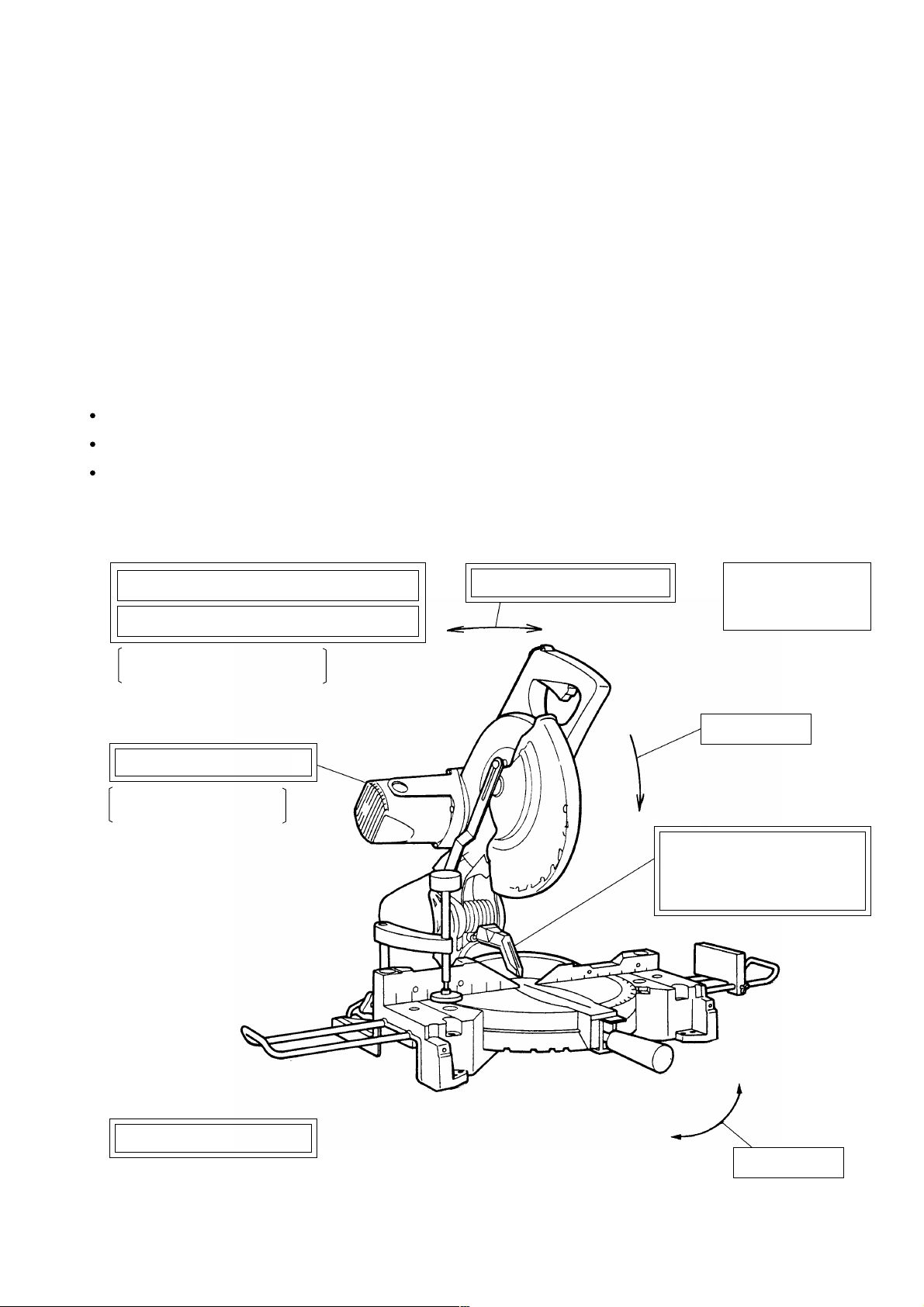
4. SELLING POINTS
(6)
Minimized reaction during motor start up
(7)
Poly V belt overload protection
Electronically controlled soft
start and motor torque
(5)
Fine surface finish on cuts
Electronically controlled
constant-speed
(3)
Right and left bevel cutting
(4)
Compound miter
and right/left bevel
cutting
(1)
Press cutting
(8)
Equipped with debris guard
to restrict dispersion of chips
for enhanced safety in
operation
(9)
Lightweight design: 13 kg
(Note) Numerals in ( ) are identical with item numbers in "4-1. Selling Point Descriptions"
--- 1 ---
Left
Right
(2)
Miter cutting
4-1. Selling Point Descriptions
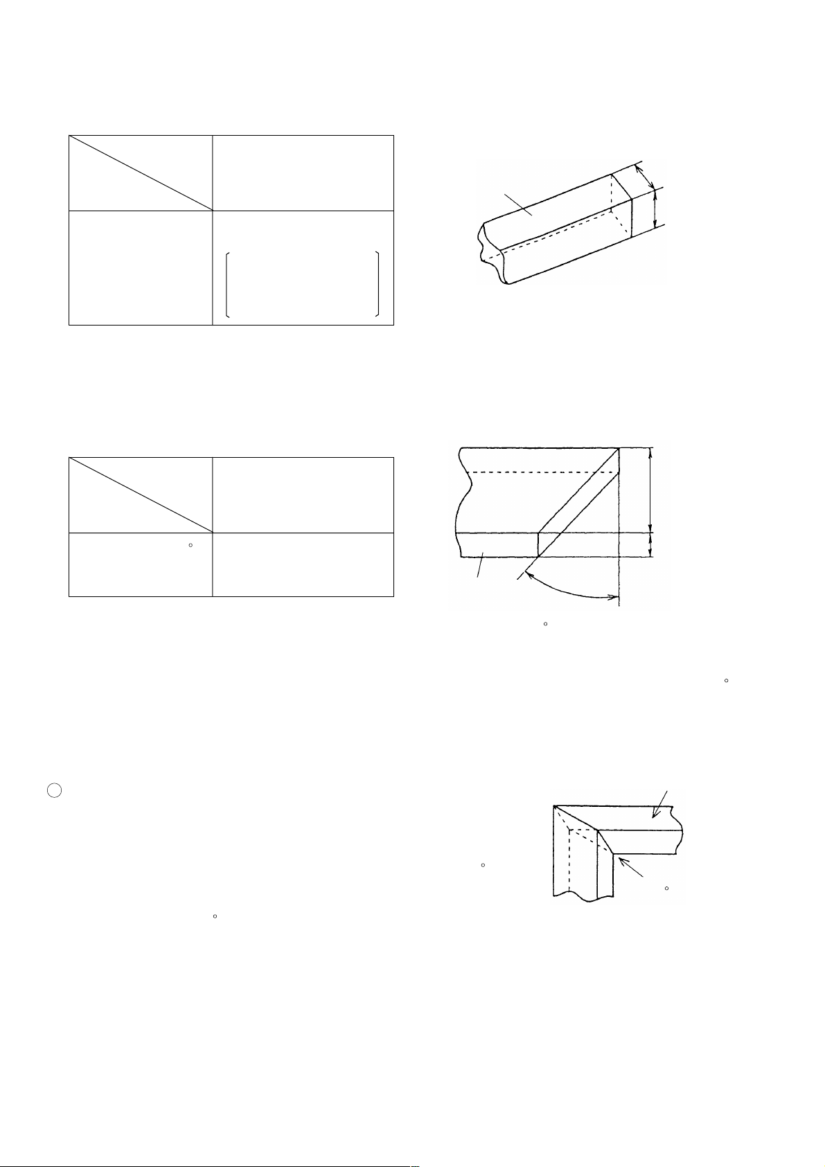
(1) Press cutting
Table 1
(Unit: mm)
Maker
model
Max. cutting
HITACHI
C 10FCD
Workpiece
Width (W)
dimension
69 x 143
(2-23/32" x 5-5/8")
Height x Width
(H x W)
89 x 92
(3-1/2" x 3-5/8")
with aux. board width
17 mm (11/16")
Fig. 1
Press cutting with the head swiveling enables cutting square workpieces as large as shown in Table 1 in a
single sawing operation. (See Fig. 1)
(2) Miter cutting facility
Table 2
(Unit: mm)
Maker
model
Max. cutting
HITACHI
C 10FCD
Width (W)
dimension
Height (H)
Right and left 45
Height x Width
(H x W)
69 x 98
(2-23/32" x 3-7/8")
Workpiece
Right and left
45
Height (H)
Fig. 2
By turning the table to the right or left as desired, the Model C 10FCD is capable of miter cutting of up to 45 to
the right and left.
(3) Right and Left bevel cutting facility
1 Advantage of right and left bevel cutting
Window frames
Fig. 4 shows the left bevel cutting by C 10FC2 and Fig. 5 shows the
right and left bevel cutting by C 10FCD.
The purpose of right and left bevel cutting is to achieve accurate 45
bevel cutting for better miter joint work. Generally, window frames
are made by jointing 45 bevel (miter) cut workpieces. (See Fig. 3)
Miter cutting
(45 bevel cutting)
Fig. 3
(a) In the case of C 10FC2, miter cutting is performed by the left bevel cutting function only as shown in Fig. 4.
Therefore, the workpiece must be turned around in the second process and the reference plane, that is, the
surface of the workpiece which contacts to the fence is opposite to that of the first process.
(b) In the case of C 10FCD, more accurate miter cutting is performed because the same reference plane (surface
of the workpiece which contacts to the fence) is used in both the first and the second processes as shown in
Fig. 5. In addition, the working efficiency is improved and long workpieces can be handled in tight places
because there is no need to turn around the workpieces.
--- 2 ---

First process
First process
Saw blade
Second process
Reference plane in
the second process
(surface of the
workpiece which
contacts to the fence)
Fig. 4 Miter cutting by C 10FC2
Reference plane in the first process
(surface of the workpiece which
contacts to the fence)
Turn around
Reference plane
in the first process
Reference plane in the first process
(surface of the workpiece which
contacts to the fence)
Second process
Same reference plane as the first process
Fig. 5 Miter cutting by C 10FCD
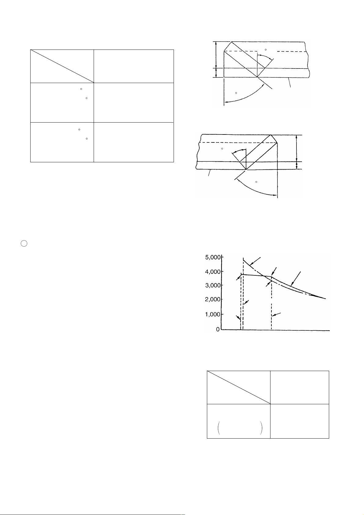
2 Maximum cutting dimension
Table 3
Maker
model
Max. cutting
dimension
Right 45
Height x Width
(H x W)
Left 45
Height x Width
(H x W)
Workpieces as wide as shown in Table 3 can be bevel-cut by tilting the saw blade section (head).
HITACHI
C 10FCD
24 x 120
(15/16" x 4-3/4")
45 x 143
(1-25/32" x 5-5/8")
(Unit: mm)
Workpiece
Right 45
Left 45
Fig. 6
Width (W)
Height (H)
--- 3 ---
(4) Compound cutting through use of miter and bevel cutting functions
Max. cutting
Maker
model
Table 4
HITACHI
C 10FCD
(Unit: mm)
Width (W)
Height (H)
dimension
45
(Right)
Right bevel 45
Right/Left miter 45
Height x Width
24 x 85
(15/16" x 3-11/32")
(H x W)
Left bevel 45
Right/Left miter 45
Height x Width
45 x 130
(1-25/32" x 5-1/8")
(H x W)
By turning the table to the right or left and inclining the
saw blade section (head) to the right or left, the Model
C 10FCD is capable of compound cutting (bevel and
miter, see Figs. 7 and 8) of workpieces with the maximum
dimensions shown in Table 4.
(5) Fine surface finish on cuts
1 Constant-speed cutting is achieved by minimizing
revolution variation due to changes in load during sawing
by means of an electronic control, as in the C 10FCD.
As indicated in Fig. 9, revolution variation during sawing is
electronically held to a minimum, while providing a higher
(Left)
45
Workpiece
Rotation speed
(/min)
3800
45
(Right)
Fig. 7
45 (Left)
Fig. 8
3400
Workpiece
Width (W)
Height (H)
Models without electronic
control
3700
HITACHI
C 10FCD
rotation speed during sawing than in the competitiors'.
With this considerably higher speed during sawing (over
No-load
current
No-load current
Rated current
the normal load range), the amount of material cut per
tooth is reduced to ensure a finer quality finish on the cut
surface. Uneven cut surfaces at the start of sawing are
Load current (A)
Fig. 9
caused by numerous runouts of the saw blade due to
revolution changes dependent on load variation.
The electronic control provided in the C 10FCD serves to
maintain relatively constant rotation in a range at which run
out of the saw blade is minimized, even at the no-load
speed. This minimizes surface unevenness during the first
part of the cut. Besides the outstanding feature of cutting
speed which is independent of load variation over a wider
Table 5
Maker
model
Item
No-load sound
presure level
1 m distance
fromthe front
[Unit: dB(A)]
HITACHI
C 10FCD
85
range of operation (for a smooth cut surface with few saw marks), electronic control also offers advantages of
eliminating the sharp metallic noise due to resonance of the saw blade as well as noises during no-load
operation because the no-load speed is maintained at 3,800 /min. (See Table 5)
--- 4 ---

(6) Minimized reaction during motor start
The C 10FCD uses the soft-start system to suppress sound
pressure level when starting and reaction transmitted
through the handle.
Sound pressure level and reaction when starting are as
indicated in Table 6.
A normal speed is reached quickly with minimum sound
pressure level when starting.
Item
Sound pressure level
when starting *
* Sound pressure level when starting: Maximum
value measured at 1 m distance from the front
Table 6
Maker
model
[Unit: dB(A)]
HITACHI
C 10FCD
86
It is readily seen from Table 6 that the electronically
controlled soft start is highly effective.
(7) Poly V belt overload protection
C 10FCD utilizes the poly V belt to transmit the rotation of the motor to the saw blade instead of a conventional
gear transmission system. This is to reduce noise, however, there is a fear of cutting the poly V belt during
overload. To protect the poly V belt, an overload protection circuit is equipped in C 10FCD.
The overload protection circuit stops the motor revolution before the motor locks when an excessive or
abnormal load is applied to the poly V belt, and so protects the poly V belt.
(8) Equipped with debris guard to restrict dispersion of chips for enhanced safety in operation
A debris guard has been adopted to prevent wood chips from adhering to the saw blade at the end of the
cutting operation. The debris guard tilts together with the saw blade during bevel cutting, thereby enhancing
safe operation.
(9) Lightweight design
13 kg in weight, for easy transport in a workshop
--- 5 ---
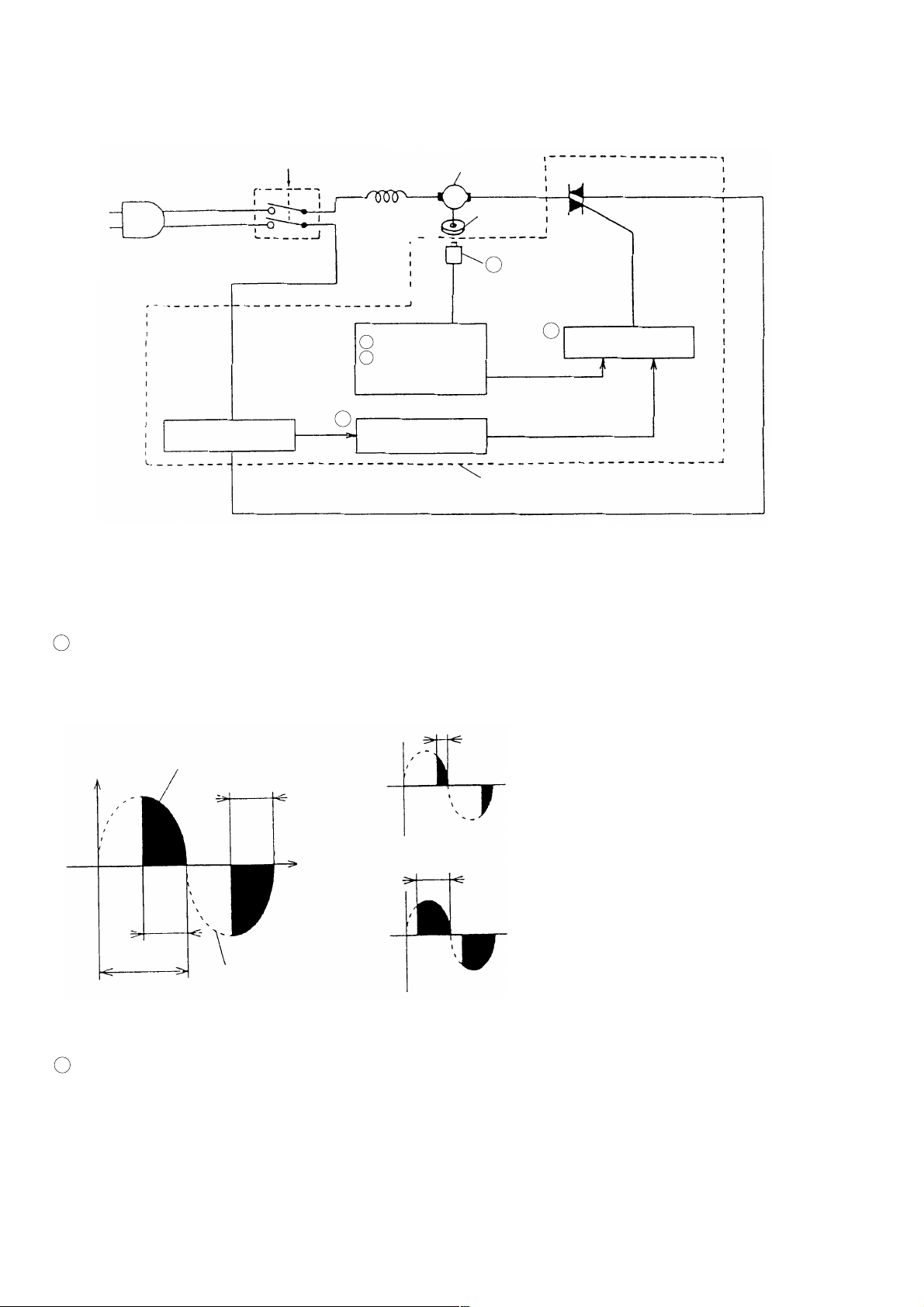
4-2. Electronic Control and Its Functions
(1) Control circuit (block diagram)
Off/On
Load current
detecting circuit
Switch
Stator coil
3 Soft start circuit
4 Constant-speed
control circuit
5
Overload
protection circuit
Motor
Fig. 10
Magnet
2 Rotation speed
detector
1
Phase control circuit
Controller
Phase control
element
(2) Functions
1 Phase control circuit
As illustrated Fig. 11, the phase control element (triac) functions to increase or decrease the time (T) of the line
voltage waveform in order to control the amount of voltage applied to the motor.
t
When ' t ' becomes smaller, motor
Voltage
Waveform of voltage
applied to motor
t
rotation speed and torque decrease.
Time
t
t
When ' t ' becomes larger, motor rotation
speed and torque decrease.
T
Line voltage
waveform (AC)
Fig. 11
When t = T, line voltage (full voltage) is applied.
2 Rotation speed detector
The rotation speed detector detects and monitors the rotation speed of the armature by means of a magnetic
sensor (magnet pick-up), incorporated in the controller, which detects flux changes generated by a magnet
mounted at the armature shaft.
--- 6 ---
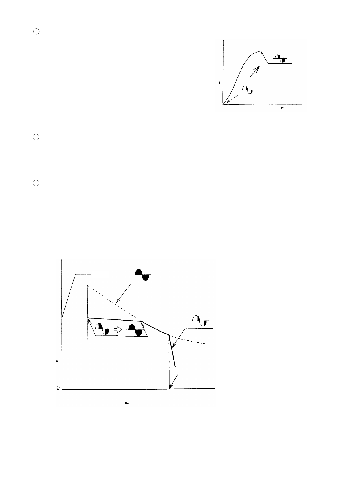
3 Soft-start circuit
When the switch is turned on, the soft start-circuit functions to
gradually increase the voltage applied to the motor, thereby
gradually increasing motor rotation speed.
Rotation speed
Switch ON
4 Constant speed control circuit
The constant speed control circuit receives signals from the rotation speed detector, and adjusts the amount of
voltage applied to the motor to keep the rotation speed of the motor as close as possible to a predetermined
value.
5 Overload protection circuit
When an overload sensor detects a motor load current that exceeds the maximum load limit of the
polyethylene V-belt, the overload protection circuit generates a command to cut off the power supplied to the
motor. This circuit is also effective in preventing the motor and the phase control element from being
damaged.
Voltage applied to
motor is gradually
increased.
Time
Fig. 12
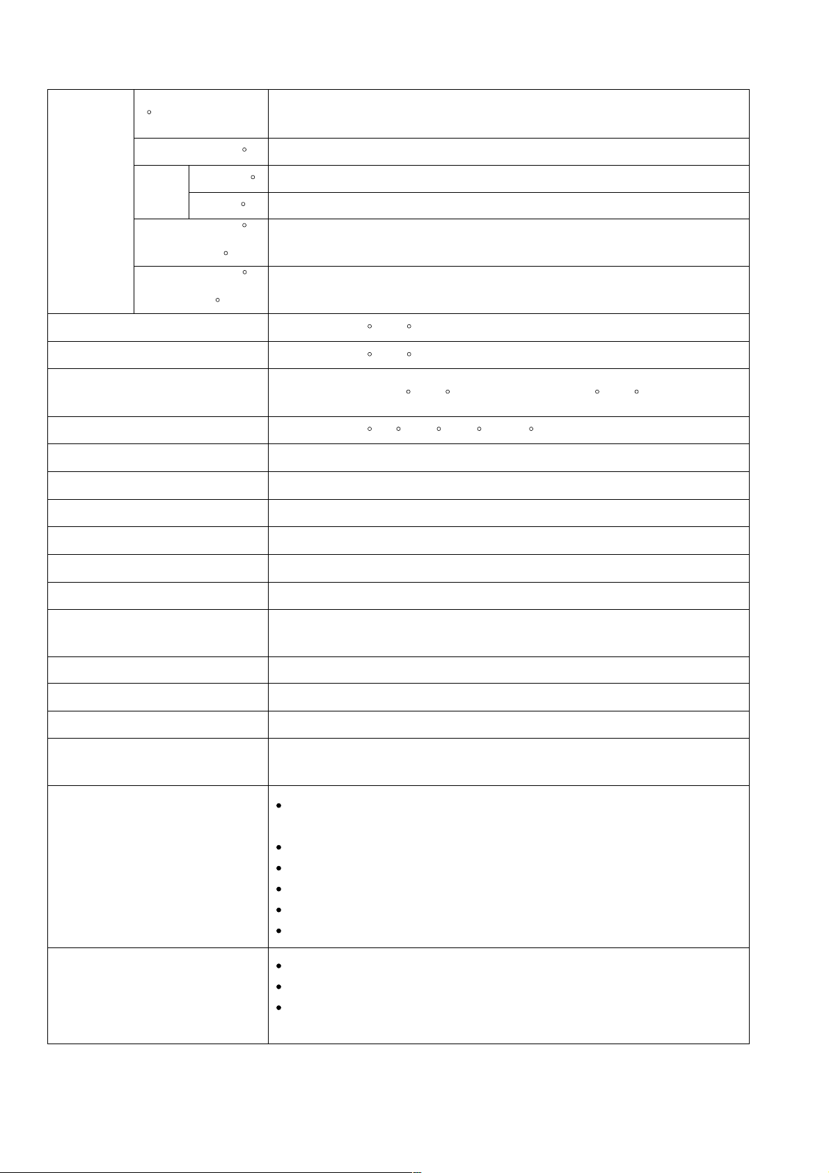
(3) Motor characteristics during electronic control
3,800
(When control is not applied)
As load increases,
Saw blade rotation speed (/min)
voltage applied to
motor increases.
Overload protection is activatedNo load
Load current (A)
Voltage applied to motor decreases
suddenly, and motor stops.
Current value determined by load
current limiter circuit
Fig. 13
--- 7 ---
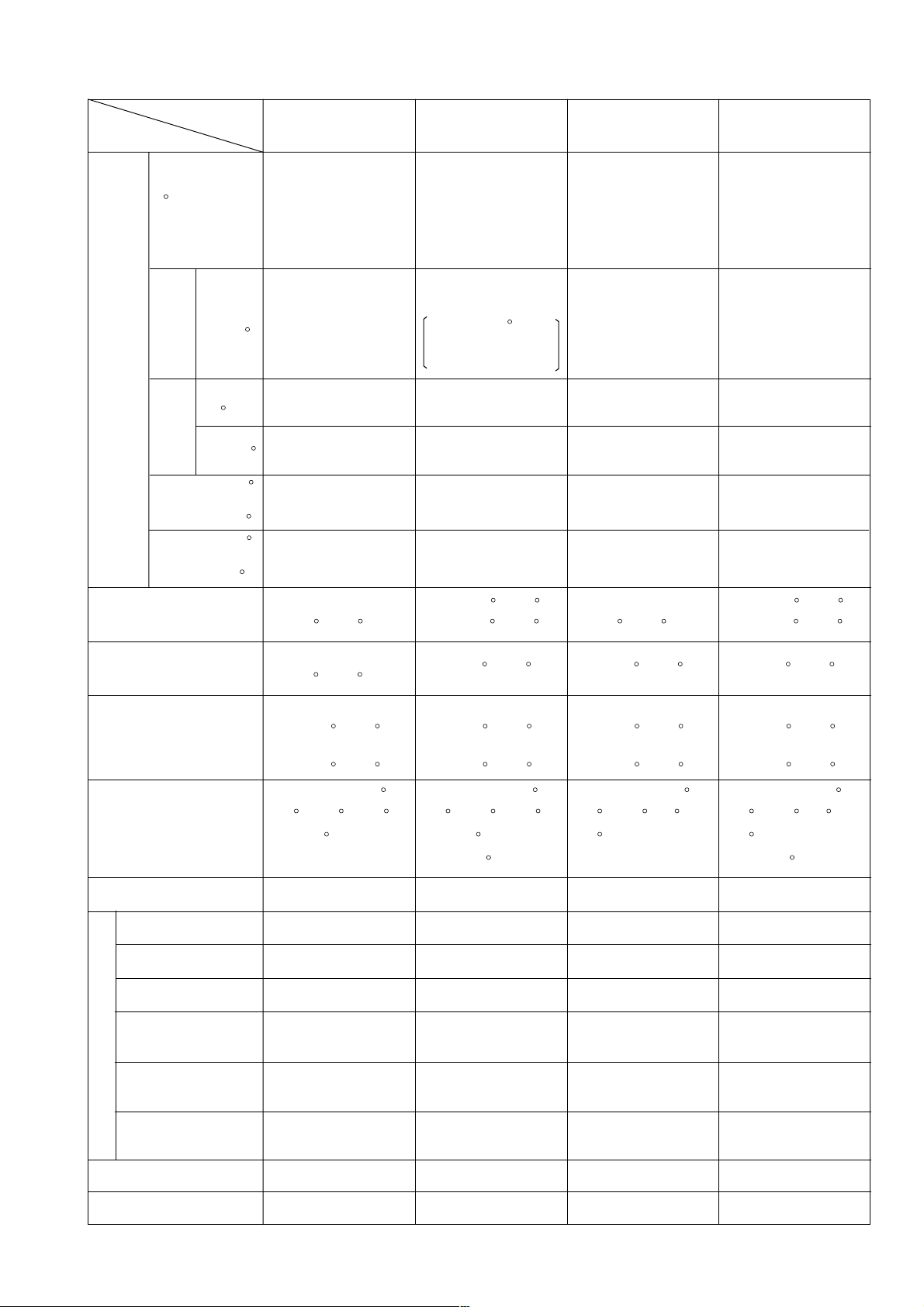
5. SPECIFICATIONS
0 (Right angle)
Maximum
cutting
dimensions
Height x
Width
(H x W)
Miter right/left 45
Right 45
Bevel
Left 45
Miter right/left 45
+
Bevel right 45
Miter right/left 45
+
Bevel left 45
Miter cutting ranges
Bevel cutting range
Compound (miter + bevel) cutting
ranges
Angle stopper positions
Applicable saw blade
Power source type and voltage
69 mm (2-23/32") x 143 mm (5-5/8")
89 mm (3-1/2") x 92 mm (3-5/8") [with aux. board width 17 mm (11/16")]
69 mm (2-23/32") x 98 mm (3-7/8")
24 mm (15/16") x 120 mm (4-3/4")
45 mm (1-25/32") x 143 mm (5-5/8")
24 mm (15/16") x 85 mm (3-11/32")
45 mm (1-25/32") x 98 mm (3-7/8")
Right and left 0 --- 45
Right and left 0 --- 45
Miter: Right and left 0 --- 45 , Bevel: Right and left 0 --- 45
Right and left 0 , 15 , 22.5 , 31.6 and 45
255 mm (10") external dia. x 15.9 mm (5/8") bore
AC single phase 60 Hz, 115 V
Type of motor
Full-load current
No-load rotation speed
Max. output
Main body dimensions
(Width x Depth x Height)
Weight
Coating
Packaging
Cord
Standard accessories
AC single phase commutator motor
115 V --- 13 A
3,800 /min
1,600 W
500 mm x 625 mm x 605 mm
(19-11/16" x 24-5/8" x 23-13/16")
13 kg (28.7 lbs) Gross weight 16 kg (35.3 lbs)
Metallic silver green
Corrugated cardboard box
Type: 2-Conductor cabtire cable Norminal cross-sectional area: 1.25 mm
Length: 2 m (6.6 ft) External dia: 8 mm with mold plug
255 mm (10") TCT saw blade (24 teeth, Code No. 790004)
••••••••••••
for wood and aluminum cutting
Dust bag
Vise ass'y
Extension stay
Machine screw M5
Wrench
2
Optional accessories
Holder ass'y (Code No. 317542)
Vise ass'y (Code No. 317541)
255 mm (10") TCT saw blade (70 teeth, Code No. 976473)
••••••••••••
for normal cutting
--- 8 ---
6. COMPARISONS WITH SIMILAR PRODUCTS
Maker/Model
Item
HITACHI
C 10FCD
HITACHI
C 10FC2
S
C
0
(Right angle)
Max.
cutting
Miter
Right/
left 45
dimensions
Height
x Width
(H x W)
Right
45
Bevel
Left 45
Miter right/left 45
+
Bevel right 45
Miter right/left 45
+
Bevel left 45
Miter cutting ranges
69 mm x 143 mm
(2-23/32" x 5-5/8")
89 mm x 92 mm
(3-1/2" x 3-5/8")
[with aux. board width
17 mm (11/16")]
69 mm x 98 mm
(2-23/32" x 3-7/8")
24 mm x 120 mm
(15/16" x 4-3/4")
45 mm x 143 mm
(1-25/32" x 5-5/8")
24 mm x 85 mm
(15/16" x 3-11/32")
45 mm x 98 mm
(1-25/32" x 3-7/8")
Right and left
0 --- 45
67 mm x 146 mm
(2-5/8" x 5-3/4")
89 mm x 92 mm
(3-1/2" x 3-5/8")
[with aux. board width
17 mm (11/16")]
70 mm x 89 mm
(2-3/4" x 3-1/2")
Right 60
70 mm x 73 mm
(2-3/4" x 2-7/8")
---
44 mm x 130 mm
(1-3/4" x 5-1/8")
--- --- ---
44 mm x 89 mm
(1-3/4" x 3-1/2")
Right 0 --- 60
Left 0 --- 45
70 mm x 146 mm
(2-3/4" x 5-3/4")
70 mm x 105 mm
(2-3/4" x 4-1/8")
---
44 mm x 146 mm
(1-3/4" x 5-3/4")
44 mm x 105 mm
(1-3/4" x 4-1/8")
Right and left
0 --- 45
69 mm x 130 mm
(2-3/4" x 5-1/8")
69 mm x 92 mm
(2-3/4" x 3-5/8")
---
35 mm x 130 mm
(1-3/8" x 5-1/8")
35 mm x 92 mm
(1-3/8" x 3-5/8")
Right 0 --- 52
Left 0 --- 45
Bevel cutting ranges
Compound
(miter + bevel)
cutting ranges
Miter: Right and left
Bevel: Right and left
Right and left 0 ,
Angle stopper position
15 , 22.5 , 31.6
and 45
Saw blade outer diameter (mm)
Full-load current (A)
No-load revolution (/min)
Max. output (W)
Soft-start
Motor
Speed control
(electronic control)
(electronic control)
Right and left
0 --- 45
0 --- 45
0 --- 45
255 (10")
115 V --- 13A
3,800
1,600
Provided
Provided
Left 0 --- 45
Miter: Right and left
0 --- 45
Bevel: Left
0 --- 45
Right and left 0 ,
15 , 22.5 , 31.6
and 45
Right 60
255 (10")
115 V --- 15 A
4,900
2,200
No
No
Left 0 --- 45
Miter: Right and left
0 --- 45
Bevel: Left
0 --- 45
Right and left 0 ,
15 , 22.5 , 30 and
45
255 (10")
115 V --- 15 A
4,900
---
No
No
Left 0 --- 45
Miter: Right and left
0 --- 45
Bevel: Left
0 --- 45
Right and left 0 ,
15 , 22.5 , 30 and
45
Right 52
255 (10")
115 V --- 15 A
4,600
---
No
No
Poly V belt
overload protector
Saw blade drive system
Insulation structure
Provided
(electronic control)
Poly V belt and gear
Double insulation
No
Gear
Double insulation
--- 9 ---
No
Gear
Double insulation
No
Gear
Double insulation

Maker/Model
Item
Base size
width x depth (mm)
HITACHI
C 10FCD
500 x 120
(19-11/16" x 4-3/4")
HITACHI
C 10FC2
525 x 150
(20-1 1/16" x 5-29/32")
S
455 x 125
(17-15/16" x 4-15/16")
C
460 x 135
(18-3/32" x 5-5/16")
Debris guard
Dust bag size (mm)
Main unit dimensions
(Width x Depth x
Height) (mm)
Standard accessories
Optional accessories
Provided
300 x 190
(11-13/16" x 7-15/32")
500 x 625 x 605
(19-11/16" x 24-5/8"
x 23-13/16")
13 (28.7 lbs)Product weight (kg)
TCT saw blade
(24 teeth)
Dustbag
Vise ass'y
Extension Stay
5 mm Machine
Screw
Wrench
Holder ass'y
Vise ass'y
255 mm TCT saw
blade (70 teeth)
for normal cutting
Provided
300 x 190
(11-13/16" x 7-15/32")
535 x 600 x 489
(21-1/16" x 23-1/2"
x 19-1/4")
14.5 (32 lbs)
TCT saw blade
(24 teeth)
Dustbag
Vise ass'y
Wrench
Holder ass'y
255 mm TCT saw
blade (70 teeth)
for normal cutting
No
320 x 190
(12-19/32" x 7-15/32")
455 x 595 x 535
(17-29/32" x
23-13/32" x 21")
22 (49 lbs)
Combination saw
blade (104 teeth)
Dustbag
Vise ass'y
(Horizontal)
Holder ass'y
Wrench
No
300 x 150
(11-13/16" x 5-15/16")
476 x 530 x 532
(18-3/4" x 20-7/8" x
20-15/16")
11 (24.2 lbs)
TCT saw blade
Dustbag
Auxiliary plate
13 mm Socket
wrench
Wrench
Triangular rule
Safety goggles
--- 10 ---

7. PRECAUTIONS IN SALES PROMOTION
In the interest of promoting the safest and most efficient use of the Model C 10FCD Compound Saw by all of our
customers, it is very important that at the time of sale the salesperson carefully ensures that the buyer seriously
recognizes the importance of the contents of the Instruction Manual, and fully understands the meaning of the
precautions listed on the various Caution Plates attached to each machine.
7-1. Instruction Manual
Although every effort is made in each step of design, manufacture and inspection to provide protection against
safety hazards, the dangers inherent in the use of any power saw cannot be completely eliminated. Accordingly,
general precautions and suggestions for the use of electric power tools, and specific precautions and suggestions
for the use of the compound saw are listed in the Instruction Manual to enhance the safe, efficient use of the tool
by the customer. Salespersons must be thoroughly familar with the contents of the Instruction Manual to be able
to offer appropriate guidance to the customer during sales promotion.
(1) Precautions on the Name Plate
Each Model C 10FCD is furnished with a Name Plate that lists the following precautions.
CAUTION
For safe operation, see instruction manual.
Do not expose to rain or use in damp locations.
(2) Warning Label (A)
WARNING
For Your Own Safety Read Instruction
Manual Before Operating Miter Saw.
1. Wear eye protection.
2. Keep hands out of path of saw blade.
3. Do not operate saw without guards in place.
4. Do not perform any operation freehand.
5. Never reach around saw blade.
6. Turn off tool and wait for saw blade to stop
before moving workpiece or changing settings.
7. Disconnect power before changing blade or servicing.
8. Saw blade diameter is 10" (255 mm).
9. No load speed is 3800 /min.
(3) Caution Label (E)
CAUTION
When the Poly-V-belt becomes overloaded, the
overload protective device cuts off the current to stop
the motor. In this case turn the switch off immediately
and raise the handle to its initial position. Then turn the
switch on and run the tool for 20 seconds without load
for cooling of the motor. Then start the cutting
operation. The Poly-V-Belt or the motor will be
damaged if the overload protective device turns off
frequently.
The Warning Label (A) specified by the UL is affixed
on the upper righthand portion of the base. Please
instruct users to strictly observe the contents in 1 to 9
in the Warning Label (A) shown at left.
H390727
The Caution Label (E) is affixed on the side of the rear
cover. Please instruct users to strictly observe the
Caution Label (E).
H390973
--- 11 ---

8. ADJUSTMENT AND OPERATIONAL PRECAUTIONS
8-1. Confirmation of Saw Blade Lower Limit Positioning
6 mm Depth
adjustment
screw
The lower limit of the saw blade cutting depth is factory adjusted
so that when the saw blade is fully lowered, its cutting edge is
24 mm to 28 mm (1-1/32" to 1-3/32") below the upper surface of
the table insert. Lower the saw blade and confirm that it stops at
the correct position.
If it is necessary to adjust the saw blade lower limit, loosen the
6 mm lock nut on the 6 mm depth adjustment screw, and turn the
6 mm depth adjustment screw if necessary. (See Fig.14)
[Caution] Perform the adjustment carefully to ensure that the saw blade does not cut into the table.
Also, on completion of adjustment, ensure without fail that the 6 mm lock nut is securely
tightened.
8-2. How to Use the Vise Ass'y
(1) The vise ass'y can be mounted on either the left side
base or the right side base, and can be raised or
lowered according to the height of the workpiece.
Fig. 14
6 mm
Lock nut
Knob
Vise ass'y
1 Insert the support of the vise ass'y into the hole
located on eigher the left side base or the right side
base.
2 Then tighten the 5 mm clamp bolt as shown in Fig. 15.
3 Turn the knob to thoroughly clamp the workpiece.
(NOTE) The support has two locking grooves into which
the tip of the 5 mm clamp bolt is designed to fit, to
lock the vise ass'y in the desired position.
(2) The vise ass'y can be mounted on either the left side
fence or the right side fence, and can be raised or
lowered according to the height of the workpiece.
1 Insert the support of the vise ass'y into the hole
located on either the left side fence or the right side
fence.
2 Then tighten the 5 mm clamp bolt as shown in Fig. 16.
3 Turn the knob to thoroughly clamp the worikpiece.
Knob
Vise ass'y
Support
Fence
5 mm
Clamp bolt
Base
5 mm
Clamp bolt
Fig. 15
Fig. 16
[Caution] Always confirm that the motor head does not contact the vise ass'y when it is lowered for
cutting. If there is any danger that it may do so, loosen the 5 mm wing bolt slightly and move
the vise ass'y to a position where it will not contact the saw blade.
--- 12 ---

8-3. Cutting Operation
(1) Cutting efficiency will be reduced if a dull saw blade is used, if an excessively long extension cord is used, or if
the wire gauge of the extension cord is too small. (For details on extension cords, please refer to the
Instruction Manual.) This is particularly important when cutting materials with dimensions which are at or near
the maximum capacity for the machine.
(2) The customer should be advised to thoroughly inspect the workpiece to ensure that there are no metallic
objects (nails in particular), sand or other foreign matter in or on the workpiece. Saw blade contact with such
foreign matter will not only shorten the service life of the saw blade, but could cause serious accident. Should
the saw blade tips be broken off, the tips may fly toward the operator.
(3) Press cutting
Like Model C 10FC2 can be used for press cutting of workpieces up to 69 mm x 143 mm (2-23/32" x 5-5/8") in
a single operation by simply pushing the saw blade section (head) downward. The customer should be
cautioned that excessive pressure on the handle will not increase the cutting speed. On the contrary,
excessive pressure may result in reduced cutting efficiency (irregular or rough cutting of the workpiece), and
could also cause overload and subsequent burnout of the motor.
On completion of the cutting operation, turn the switch OFF and wait for the saw blade to come to a complete
stop before raising the saw blade section (head) to its original position. Raising the saw blade section (head)
while the saw blade is rotating may cause unwanted cutting marks on the workpiece.
Techniques to avoid unwanted cutting marks
Uneven and unwanted cutting marks can be avoided throughout the cutting operation by gently and smoothly
pressing down on the handle, so that the entire cutting operation is accomplished in a single uninterrupted
motion.
(4) Miter cutting
Miter cutting is accomplished by turning the table. (For details, please refer to the Instruction Manual.)
(5) Bevel cutting
Bevel cutting of 0 --- 45 to the right or left is accomplished by inclining the saw blade section (head).
(For details, please refer to the Instruction Manual.)
[Caution] When the workpiece is secured on the right or left
side, the cut off portion comes to rest on the side of
the saw blade as illustrated in Fig. 17. If the handle is
raised before the saw blade rotation comes to a
complete stop, there is a chance that the cut off
Fixed-side workpiece
Cut-off-side
workpiece
portion of the workpiece could become jammed
against the saw blade, causing a hazardous
condition. Instruct the customer to ensure without
fail that the saw blade comes to a complete stop
before attempting to raise the handle.
--- 13 ---
Saw blade
Fig. 17

(6) Compound (miter + bevel) cutting
Compound cutting can be accomplished by combining the miter cutting and bevel cutting operations described
in paragraphs (4) and (5) above. (For details, please refer to the Instruction Manual.)
When the saw blade section (head) is inclined 45 to the right or left, the table can be turned up to 45 to the
right and left.
(7) Cut surface quality during miter/bevel cutting
The quality of the cut surface depends on the type of
cutting operation (miter or bevel), the type and
sharpness of the saw blade, whether the workpiece
is cut to the right or left, and various other factors. In
miter and bevel cutting in particular, cutting is
performed across the wood grain, so the condition of
the cut surface depends on whether the wood is cut
with or against the grain. This is the sames as when
using electric portable planers. Customers should
be advised of these phenomena so that they
understand that in cases when the cut surface may
not be as smooth as expected or hoped for, it is not
caused by the performance of the saw blade or the
Model C 10FCD.
In the cutting examples illustrated in Fig. 18, the cut
surfaces on the sides marked A are better than
A
Better
[Left bevel cutting]
B
[Miter cutting]
B
A
Better
B
[Right bevel cutting]
A
Better
Fig. 18
A
Better
B
those on the sides marked B .
--- 14 ---

8-4. Precautions Concerning Electronic Control
(1) Polyethylene V-belt overload protection
The rotation of the motor is transferred to the saw blade by a polyethylene V-belt. When an extremely heavy
or abnormal load is applied to the polyethylene V-belt, the overload protection circuit functions to stop the
motor, protecting the V-belt from wear or damage due to slipping.
In such a case, instruct the customer to immediately turn the switch OFF, lift up the handle, and return the saw
blade section (head) to its original position. Then, turn the switch ON, and allow the machine to idle about 20
seconds so that the motor can be cooled by the motor fan. When the sow blade rotation speed returns to
normal, cutting can be resumed.
In addition, the customer should be advised to give particular attention to the following points:
1 Avoid cutting operations that cause the overload protection circuit to function repeatedly.
[Reason] There is a danger that the polyethylene V-belt and/or motor may be damaged.
2 Do not restart cutting until the saw blade rotation speed has returned to normal.
[Reason] If cutting is restarted before the rotation speed returns to normal, the overload protection circuit
will function again, even with a light load.
Even if the switch is not turned OFF after the saw blade section (head) has been raised to its original position,
the rotation speed will return to normal. However, it takes longer (4 to 10 seconds) than if the switch is turned
OFF and then turned ON again so that the soft-start circuit functions.
Accordingly, turning the switch OFF and then ON again allows the operator to restart the cutting operation
more quickly and more safely.
(2) Operating the Model C 10FCD near an electric welding machine may cause fluctuations in the rotation speed.
The control circuit in the Model C 10FCD contains a magnetic sensor (a flux change detecting element) and a
triac (which may malfunction because of excessive electrical noise). Accordingly, customers should be
advised not to operate the Model C 10FCD in the immediate vicinity of other machines that generate
extremely strong magnetic fields or excessive electrical noise.
(3) Operate the machine with correct voltage supply
Large voltage drops caused by an unstable power supply may cause the overload protection circuit to
function, or lower the output of the motor and affect efficient cutting. Advise the customer to check the power
supply before operating the machine.
In addition, the customer should be advised to pay particular attention to the following points:
1 If an extension cord is used, it should be kept as short as possible and within the requirements listed in the
Instruction Manual.
[Reason] An excessively long extension cord causes voltage drop.
2 Direct current (DC) cannot be used.
[Reason] The built-in controllers will only function with alternating current (AC).
--- 15 ---

9. ADJUSTMENT OF COMPONENTS
9-1. Bevel Angle Adjustment
When shipped from the factory, the heights of 6 mm
bolt (A), 6 mm bolt (B) and 5 mm hex. socket. hd. bolt
(C) are adjusted so that the saw blade section (head)
will stop at 0 (right-angle), 45 to the left and 45 to the
right. To change the head stop positions, instruct the
customer to adjust the height of 6 mm bolt (A), 6 mm
bolt (B) and 5 mm hex. socket. hd. bolt (C) as
described below. For example, to change the 45 to the
right stopper, pull up the locating bar in the direction
indicated by the arrow in Fig. 21 and tilt the head to the
right.
When setting the head to the 0 position, be sure to
replace the locating bar (press down it in the opposite
direction from that indicated by the arrow in Fig. 20.
As illustrated in Fig. 19, adjustment of the 0 (right
angle) can be accomplished by loosening the 5 mm nut
(lock nut) and turning the 5 mm hex. socket hed. bolt
(C) to raise or lower it by an appropriate dimension to
change the position at which it comes in contact with
locating bar.
On completion of adjustment, ensure that the 5 mm nut
(lock nut) is securely tightened.
Clamp handle
Locating bar
Bevel angle
scale
Indicator
6 mm Nut
(Lock nut)
5 mm Hex. socket
hd. bolt (C)
(Stopper for 0 )
Fig. 19
Clamp handle
Locating bar
6 mm Bolt (A)
(Stopper for right 45
bevel angle)
Fig. 20
As illustrated in Figs. 20 and 21, adjustment of the
bevel angle can be accomplished by loosening the 6
mm nut (lock nut) and turning the 6 mm bolt (A) and 6
mm bolt (B) to raise or lower it by an appropriate
dimension to change the position at which it comes in
contact with angle regulator.
On completion of adjustment, ensure that the 6 mm nut
(lock nut) is securely tightened.
Adjustment of the squareness of the saw blade with
relation to the table can also be accomplished by
adjusting the stopper bolts as described above.
Clamp handle
Locating
5 mm Hex. socket
hd. bolt (C)
(Stopper for 0 )
Pull
up
bar
6 mm bolt (B)
(Stopper for left 45
bevel angle)
6 mm Nut
(Lock nut)
Fig. 21
--- 16 ---

10. PACKING
The main body of the Model C 10FCD is sandwiched between packing (A) and packing (B) made of styrofoam.
This system makes the packaging work easier.
(1) Preparation
Remove the vise ass'y, extension stay and dust bag from the main unit.
Then swivel the table through 45 toward the right.
Fix the angle regulator securely with the clamp lever.
Position the clamp lever vertically to keep the clamp lever from contact with packing (A) when putting the main
unit on packing (A).
Push down the head section and insert the plunger handle to secure the head section at the lower position.
(2) How to install packing (A)
Put packing (A) in the carton box.
Put the main unit in packing (A).
(3) How to install packing (B)
Put packing (B) on the main unit. Put the vise ass'y, the extension stay and the dust bag in the groove of
packing (B).
Close the lids of the carton box and bind them together.
--- 17 ---

11. PRECAUTIONS IN DISASSEMBLY AND REASSEMBLY
11-1. Disassembly
Special attention in disassembly should be given to the following items.
The circled numbers in the following figures and the [Bold] numbers in the descriptions below correspond to the
item numbers in the Parts List and the exploded assembly diagrams.
* Be sure to first disconnect the power plug when performing disassembly and replacement of the saw blade.
Item
No.
1
Disassembly
points
Switch
Controller (R)
Cutter shaft
703
15
16
17
131
59
58
57
Disassembly procedure Necessary tools
24
60
61
62
130
19
20
25
21
22
26
65
23
27
28
66
34
141
29
33
32
38
37
36
35
45
67
68
69
44
46
30
31
132
47
39
48
49
133
40
41
42
43
64
63
18
93
3
2
1
5
4
8
10
7
6
9
11
12
13
14
94
160
95
159
701
96
Fig. 22
--- 18 ---

Item
No.
Disassembly
points
Disassembly procedure Necessary tools
1 Switch
Controller (R)
Cutter shaft
(Continued)
1. Loosen the Counter Hd. Screw M5 x 12 [60] and turn the Cutter
Shaft Guard [61] upward so that the Bolt (Left Hand) M8 x 25 [93]
can be seen.
2. Put the Wrench [702] on the Bolt (Left Hand) M8 x 25 [93] and
turn the Wrench [702] until the Bracket Stop [67] is aligned with
the groove of the Cutter Shaft [46] while pushing the Bracket Stop
[67]. Then, loosen the Bolt (Left Hand) M8 x 25 [93] and remove
the Bolt (Left Hand) M8 x 25 [93], Blade Washer M30 [94], outside
Arbor Collar [95], TCT Saw Blade [701], inside Arbor Collar [95]
and Collar D25.4 [96].
3. Put the Cutter Shaft Guard [61] back into position and tighten the
Counter Hd. Screw M5 x 12 [60].
4. Remove the three Hex. Socket Hd. Bolts M8 x 35 [6] with a 6 mm
hex. bar wrench and the three Tapping Screws D4 X 25 [9] with a
Phillips screwdriver. Remove the Handle Cover [3].
5. Remove the Spring [10] and the Switch Lock [11].
6. Remove the two Truss Hd. Tapping Screws D4 x 12 [12] and the
Switch [13].
Phillips
screwdriver
Wrench
(Accessory)
6 mm Hex. bar
wrench
Phillips
screwdriver
7. Disconnect the four internal wires from the Switch [13].
8. Remove the two Tapping Screws D4 X 12 [5] and the Cord Clamp
[4].
9. Remove the Machine Screw M8 x 20 [14] to remove the Handle
[7]. Remove the Wire Protector [25].
10. Remove the three Machine Screws M5 x 16 [31] to remove the
Rear Cover [30].
11. Remove the V-Belt [24].
12. Remove the three Tapping Screws (W/Washers) D4 x 16 [29] to
remove the Connector Box Cover [28].
13. Remove the three Tapping Screws D4 x 16 [33] to remove the
Controller (R) [32] and the Insulating Sleeve [141].
14. Disconnect the three internal wires from the Controller (R) [32].
15. Remove the Connector Box [26].
16. While holding a 13 mm wrench on the dihedral width portion of the
Pulley (A) [21], remove the Bolt M6 x 16 [23]. Remove the Flat
Washer 1/4" x 3/4" [22], Pulley (A) [21], Magnet [20] and Flat
Washer M13 [19].
13 mm Wrench
17. Push in the Bracket Stop [67] to lock the Cutter Shaft [46].
Remove the Chuck Nut M8 [41] with a 13 mm wrench to remove
the Flat Washer [40] and Pulley (B) [39].
18. Remove the three Machine Screws M5 x 16 [42] to remove the
Gear Box [43].
--- 19 ---

Item
No.
Disassembly
points
Disassembly procedure Necessary tools
1 Switch
Controller (R)
Cutter shaft
(Continued)
Housing ass'y
2
Armature ass'y
Stator
19. Remove the Ball Bearing 6001VVCMPS2L [38] from the Gear
Shaft [36] with a pulley puller. Remove the Ball Bearing
608VVCM2EPS2L [49] from the Cutter Shaft [46] with the pulley
puller.
20. Remove the C-Ring [48] and pull out the Helix Gear [47] from the
Cutter Shaft [46].
21. Remove the two Round Washer Hd. Screws M5 x 8 [34].
By tapping the end surface of the Cutter Shaft [46] (TCT Saw
Blade [701] mounting side) with a plastic hammer, remove the
Cutter Shaft [46]. Remove the Gear Shaft [36].
158
154
156
155
153
157
Pulley puller
Plastic hammer
142
144
143
151
145
152
150
146
147
148
149
Fig. 23
1. Remove the two Brush Caps [149] to remove two Carbon Brushes
[148].
2. Remove the two Machine Screws (W/Washers) M5 x 25 [143] and
the two Machine Screws (W/Washers) M5 x 50 [146]. Remove the
Housing Ass'y [144] with the Armature Ass'y [154] and the Stator
Flatblade
screwdriver
Phillips
screwdriver
[151] mounted.
(1) Disassembly of the armature ass'y
1 By tapping the Arm [158] mounting surface of the Housing Ass'y
[144] with a plastic hammer, remove the Armature Ass'y [154].
2 Remove the Flow Guide [153].
--- 20 ---
Plastic hammer

Item
Disassembly
No.
2
points
Housing ass'y
Armature ass'y
Stator
(Continued)
3 PC-guard arm
Disassembly procedure Necessary tools
(2) Disassembly of the stator
1 Disconnect the Internal Wire [150] from the Brush Holder [147]
and disconnect the internal wires from the Stator [151].
2 Remove the two Machine Screws M5 x 60 [152] that fix the
Stator [151].
3 By tapping the Arm [158] mounting surface of the Housing Ass'y
[144] with a plastic hammer, pull out the Stator [151].
50
51
52
53
54
55
17
131
58
59
56
79
57
60
80
81
82
61
158
62
65
64
63
83
78
77
Fig. 24
1. Remove the Truss Hd. Step Screw M6 x 12 [50] and the Truss Hd.
Round Neck Screw M6 x 10 [51] that fix the Lever [52]. Remove
the Lever [52].
2. Secure the Special Nut Chuck M6 [62] behind the Cutter Shaft
Guard [61] with a 10 mm wrench. Remove the Counter Hd. Screw
M6 x 16 [54], Collar [55], PC-Guard [56] and Spring Guard [57].
3. While inserting the tip of a flatblade screwdriver into the groove at
the rear of the Bracket Stop [81], loosen the Plunger Handle [83]
and remove it together with the Compression Spring [82].
--- 21 ---
Phillips
screwdriver
10 mm Wrench
Flatblade
screwdriver

Item
No.
Disassembly
points
Disassembly procedure Necessary tools
3
PC-guard arm
(Continued)
Fence
4
Angle regulator
Table
70
4. Remove the Set Bolt [80].
(Note) The Set Bolt [80] serves as an upper limit stopper for the Arm
[158], so be prepared for the Arm [158] to rise up when the
Set Bolt [80] is removed.
5. Remove the two Hex. Socket Set Screws M6 x 10 [17] behind the
Arm [158] with a 3 mm hex. bar wrench.
6. Pull out the Pivot Shaft [77] by gently tapping it while holding the
Arm [158].
Removing the Pivot Shaft [77] enables you to remove the Torsion
3 mm Hex. bar
wrench
D 10 metal bar
Plastic hammer
Spring [64] and the Shaft Sleeves [63].
83
71
72
73
74
75
76
78
77
85
84
86
79
87
89
88
97
98
82
81
80
90
99
100
101
91
92
102
103
109
110
107
117
702
120
118
121
122
119
104
123
Fig. 25
105
124
128
129
125
106
126
127
114
111
112
113
108
115
116
--- 22 ---

Item
No.
Disassembly
points
Disassembly procedure Necessary tools
Fence
4
Angle Regulator
Table
(Continued)
1. Remove the three Hex. Socket Hd. Bolts M8 x 45 [117] with a
6 mm hex. bar wrench. Remove the Fence [118].
2. Turn the Clamp Lever [72] counterclockwise and remove it.
3. Remove the Nut Chuck M10 [75] with a 17 mm box wrench to
remove the Angle Regulator [79].
4. Remove the Hex. Socket Set Screw M6 x 10 [106] with a 3 mm
hex. bar wrench to remove the Pivot Shaft [99].
5. Turn the Miter Handle [116] counterclockwise and remove it.
6. Remove the two Hex. Bolts (W/Washers) M6 x 20 [114] with a
10 mm wrench to remove the Spring Plate [115].
7. Remove the Hex. Bolt (W/Washer) M6 x 20 [113] with a 10 mm
wrench. Remove the Flat Washer 1/4" x 5/8" [112] and the
Washer [111].
8. Remove the four Machine Screws M4 x 10 [109] and the Table
Insert [110].
9. With a 13 mm Box wrench, remove the Chuck Nut M8 [102] and
the Flat Washer M8 [103] from the insert space of the Table [108].
Extract the Center Shaft [129] which fixes the Table [108] to the
Base [120] by lifting the Table [108] upward.
6 mm Hex. bar
wrench
17 mm Box
wrench
3 mm Hex. bar
wrench
10 mm wrench
Phillips
screwdriver
13 mm Box
wrench
5 Bracket stop
6 Vise ass'y
158
66
Fig. 26
67
68
69
1. Remove the E-Ring [68] from the Bracket Stop [67].
2. Remove the Bracket Stop [67] and the Spring [66] from the Arm
[158].
137
Pliers
138
135
136
139
140
Fig. 27
1. Remove the Hex. Socket Set Screw M6 x 10 [135] and the
Support [136].
--- 23 ---
3 mm Hex. bar
wrench

11-2. Reassembly
Reassembly can be accomplished by following the disassembly procedures in reverse. However, special
attention should be given to following items.
(1) Prior to reassembly, measure the insulation resistance of the armature, stator, switch and other electrical
coponents and confirm that the insulation resistance of each part is more than 7 M .
(2) When reassembling the Angle Regulator [79] and the Arm [158], apply 2 grams of Hitachi Motor Grease to the
oil groove of the Arm [158].
(3) When replacing the Torsion Spring [64], apply approximately 2 grams of Hitachi Motor Grease to the inner
circumference of the new Torsion Spring [64] prior to reassembly.
(4) When replacing the Rotation Slide Plate [128], reassemble it into the unit as illustrated in Fig. 28. During
reassembly, apply 6 grams of Hitachi Motor Grease to the Rotation Slide Plate [128] against the sliding
surface of the Base [120].
102
103
108
120
128
129
Ensure that the Rotation Slide Plate [128] fits
into the groove portion of the Base [120].
Fig. 28
(5) If the Center Shaft [129] at the bottom of the Base [120] is tightened excessively, the movement of the Table
[108] will become sluggish and heavy. If the bolt is loose, it will cause vibration and looseness of the Table
[108] which will reduce cutting accuracy. Adjust the Chuck Nut M8 [102] so that the Table [108] moves
smoothly with minimum play and vibration.
--- 24 ---

11-3. Wiring Diagram
Carefully ensure that wiring is accomplished as illustrated below. As incorrect wiring will result in lack of rotation,
reverse rotation or other malfunctions, close attention is absolutely necessary.
1 Wiring diagram
Armature
ass'y
Brake coil
Stator coil
Stator ass'y
Black
Gray
Blue
1
Black
(Lead wire)
CB
Controller (R)
Fig. 29
A
Switch
1a
1b
White
Black
Power cord
2 Actual wiring diagram
1
Pick up
Gray
Stator
ass'y
Switch
1a1b
1
Black (Lead wire)
Black
Black
Power
cord
Blue
White
B
C
A
Fig. 30
11-4. Lead Wire Precautions
When connecting lead wires, be very careful not to remove the insulation covering of each lead wire more than
needed. Exposed cores of lead wires from connectors, for example, are extremely dangerous. Also, ensure that
the lead wires are not pinched between the mating surfaces of the Handle [7] and the Handle Cover [3].
--- 25 ---
Controller (R)

11-5. No-load Current
After no-load operation for 30 minutes, the no-load current values should be as follows.
Voltage, Frequency
No-load current
11-6. Reassembly Requiring Adjustment
(1) Adjustment of squareness between the saw blade (dummy disc) and the fence
Fence
Square
Saw blade or
dummy disc
Fig. 31
is flush against the side surface of the saw blade (or dummy disc), and move the Fence [118] as necessary so
that it is in an exact right angle with relation to the saw blade (or dummy disc). Finally, tighten the three Hex.
Socket Hd. Bolts M8 x 45 [117] to fix the Fence [118] in position.
115 V, 60 Hz
5.5 A Max.
After disassembly/reassembly or replacement of the Base [120],
Table [108], Fence [118] or Angle Regulator [79], it is necessary to
check the squareness between the saw blade (or dummy disc) and
the Fence [118], and perform adjustment as necessary if they are
not at an exact right angle with relation to each other. Adjustment
procedure is as follows.
First, position the saw blade (or dummy disc) so that it is in the exact
center of the groove on the Table [108] which houses the Table
Insert [110]. Next, as illustrated in Fig. 31, place a square so that it
*Dummy disc: A dummy disc is a toothless disc with the same external diameter as a saw blade, and is used to
perform accurate inspection and adjustments.
(2) Confirmation of saw blade height
The lower limit of the saw blade cutting depth is factory-adjusted so that when the saw blade is fully lowered,
its cutting edge is 26 mm to 28 mm (1-1/32" to 1-3/32") below the upper surface of the Table Insert [110].
Lower the saw blade and confirm that it stops at the correct position.
(3) Adjustment of saw blade lower limit position
When adjusting the lower limit of the saw blade, be sure to use a saw blade with an external diameter of 255
mm. Failure to properly adjust the lower limit position of the saw blade may result in the following problems.
1 Inability to obtain the maximum cutting capacities of the machine
2 There is a danger that the saw blade may come in contact with and cut into the Table [108].
The lower limit of the saw blade cutting depth is adjusted at the factory so that when the saw blade is fully
lowered, its cutting edge is 26 mm to 28 mm (1-1/32" to 1-3/32") below the upper surface of the Table Insert
[110]. If this potion is lower than the specified values, confirm without fail that it does not come in contact with
the Table [108].
If it is necessary to adjust the saw blade lower limit, loosen the Nut M6 [15] on the Hex. Socket Set Screw M6
x 20 [16], and turn the Hex. Socket Set Screw M6 x 20 [16] if necessary.
By turning the Hex. Socket Set Screw M6 x 20 [16] clockwise, the saw blade lower limit is raised.
By turning the Hex. Socket Set Screw M6 x 20 [16] counterclockwise, the saw blade lower limit is lowered.
On completion of adjustment, ensure that the Nut M6 [15] is properly tightened.
[CAUTION] Perform the adjustment carefully to ensure that the saw blade does not cut into the Table
[108].
--- 26 ---

(4) Reassembly of the Table
When reassembling the Table [108] and the Base [120], tighten the Chuck Nut M8 [102] so that the Table
[108] turns smoothly without excessive play or vibration.
During reassembly, liberally apply grease [Hitachi Motor Grease No. 29 (Code No. 930035) is recommended.]
at the points marked A in Fig. 32.
Table [108]
A
A
Base [120]
Center Shaft [129]
Fig. 32
11-7. Lubrication
Advise the customer to lubricate the machine as indicated below at least once a month. Also, prior to applying
lubrication, any sawdust, dirt or other foreign matter should be thoroughly wiped away with a soft cloth.
(1) Swiveling section of the Arm [158] and the Angle Regulator [79]
Coat the swiveling portion of the Arm [158] and the Angle Regulator [79] with machine oil.
(2) Vise ass'y section
Coat the screw threads portion of the Screw Bar [137] of the Vise Ass'y [134] with machine oil.
11-8. Product Precision
On completion of reassembly, confirm precision tolerances.
Unit : mm
Item
Run-out of saw blade (or dummy disc)
Perpendicularity between base and fence
Perpendicularity between saw blade (or dummy disc) and fence
Perpendicularity between saw blade (or dummy disc) and table
Surface alignment of
base and table (Use
the upper surface of
the base as a
reference).
0.38/220 (0.015" / 8-21/32")
0.26/60 (0.01" / 2-3/8")
0.45/100 (0.018" / 4")
0.3/70 (0.012" / 2-3/4")
Tolerance
0.45 ( 0.018")
0
--- 27 ---

12. REPAIR GUIDE
The bracketed numbers correspond to the item numbers in the Parts List.
Item
Phenomenon Cause (s)
Factory
standard
Unit : mm
Inspection • Repair
Adjustment
•
1 Inaccurate cutting
...Inaccurate spuareness of
the cut surface
...Cut surfaces do not fit
together properly.
Fence
Table
Fig. 33
Squareness
0.45/100
Saw blade
Squareness
0.3/70
Fence
a Inaccurate
squareness between
the table and the saw
blade causes the saw
blade to cut into the
workpiece at an
angle.
b Excessive deflection
of the saw blade
(Excessive vibration)
c Inaccurate
squareness between
the fence and the
saw blade
0.3/70
(Dummy disc)
(Fig. 33)
0.38/220
(Dummy disc)
0.45/100
(Fig. 34)
Adjust squareness with the
Hex. Socket Set Screw M6
x 25 [105].
Replace the Arm [158], the
Angle Regulator [79].
(If deformed.)
Replace the Saw Blade
[701].
Check for surface defects
on the Arbor Collar [95] and
the Collar [96], and repair
with a file as necessary.
Replace the Arbor Collar
[95] and the Collar [96] as
necessary.
Loosen the Hex. Socket Hd.
Bolt M8 x 45 [117] and
adjust as necessary.
Replace the Fence [118] as
necessary.
Fig. 34
Fig. 35
Squareness
0.26/60
Fig. 36
Saw blade
0.2 or less
Fence
0.2 or less
Fence
d Inaccurate surface
flatness of the fence
causes workpiece to
move irregularly,
causing poor
squareness of cut
surface.
e Inaccurate surface
flatness of the table
f Inaccurate
squareness between
the fence and the
table and/or the base
causes the
workpiece to tilt at an
angle and prevent
accurate cutting.
0.2 or less
(Fig. 35)
0.2/500
0.26/60
(Fig. 36)
Replace the Fence [118] as
necessary.
Replace the Table [108].
Replace the Fence [118] as
necessary.
--- 28 ---

Item
Phenomenon Cause (s)
Factory
standard
Inspection • Repair
Adjustment
•
(Continued)
1
Base
Fig. 37
Table
g Excessive
misalignment of the
base and the table
causes the saw blade
to cut into the
workpiece at an
angle.
h Loose fitting of
swiveling portion of
the arm and the
angle regulator or
sluggish movement.
As a result,
components may be
deformed because of
unstable arm or
because the operator
must apply excessive
pressure during
operation.
i Excessively fast
cutting speed causes
deflection of the saw
blade and inaccurate
cutting.
0.45
0
(Fig. 37)
---
---
Replace the Base [120]
and/or Table [108] if
deformed.
Check the fitting surfaces of
the Arm [158], Angle
Regulator [79] and Pivot
Shaft [77] for any foreign
substance (such as cutting
dust), and remove it as
necessary.
Reduce cutting speed.
Appropriately 10 seconds
for a square wood
workpiece of 60 mm
(2-3/8").
2 Rough cut surface
Parallelism A = 0.025/54
Parallelism B = 0.02/25.4
A
Arbor collar
A
Arbor collar
Fig. 38
B
Collar
j
Excessive cutting
force (pressure) is
requires because of
dull saw blade.
k The workpiece
moves during cutting
because it is bent or
deformed.
a Large deflection of
the saw blade (It
causes rough cut
surface)
b Each surface
parallism of the arbor
collar and the collar
is inaccurate due to
surface defects
(such as impact
marks and
scratches).
c Inaccurate
squareness between
the table and the
saw blade causes
the saw blade to cut
at an improper angle
and make cutting
marks.
---
---
0.38/220
(Dummy disc)
A : 0.025/54
B : 0.02/25.4
(Fig. 38)
0.3/70
(Fig. 33)
Sharpen the Saw Blade
[701] again.
Correct bend, flex or other
deformation by planing and
try cutting.
Same as the Item 1- b .
Repair impact marks or
scratches at the Arbor
Collar [95] and the Collar
[96] or replace them if
necessary.
Same as the Item 1- a .
--- 29 ---

Item
Phenomenon Cause (s)
Factory
standard
Inspection • Repair
Adjustment
•
2 (Continued)
d Excessively fast
cutting speed
e Improper clamping of
workpiece
f The table is not fixed
with the handle bar.
g
Loose fitting of
swiveling portion of
the arm and the
angle regulator, or
sluggish movement
h Cutting operation
becomes sluggish
because workpiece
is warped or bent.
i Excessive vibration
---
---
Reduce cutting speed.
Properly clamp workpiece
with the Vise Ass'y [134].
---
During cutting, fix the Table
[108] in position with the
Miter Handle [116] without
fail.
---
---
Same as the item 1- h .
Correct warp or bend with
planer.
---
Recheck the items a , b ,
c , d , f and g .
3 Saw blade is locked.
a Excessively fast
cutting speed
b Core diameter of
extension cord is too
small.
c Excessive cutting
force is applied due
to dull saw blade.
d Incorrect saw blade
is used.
---
---
Reduse cutting speed.
Use a thicker and shorter
extension cord.
Extension
cord length
7.5 m
15 m
30 m
---
Resharpen the Saw Blade
Wire gauge
size
2
2.0 mm
2
3.5 mm
Not
recommended
[701].
---
Use a suitable Hitachisupplied saw blade.
An increased number of
teeth on the saw blade
increases the cutting
resistance. When using a
saw blade with a large
number of teeth, reduce the
cutting speed.
e The saw blade binds
in workpiece during
cutting because
workpiece is warped
or bent.
--- 30 ---
---
Correct workpiece
deformation with planer.

Item
Phenomenon Cause (s)
Factory
standard
Inspection • Repair
Adjustment
•
4 Saw blade does not rotate
when switch is triggered.
5 Saw blade runs too slow.
(Not within 3,400 --- 3,800 /min)
a The power cord is
not connected to
power supply.
b The carbon brush
wear exceeds
allowable limit
(6 mm).
c Contact failure of the
switch
d Controller failure
a Power supply
voltage is lower than
rated voltage.
---
Check power supply
voltage.
Connect the power cord to
power supply.
---
Check the Carbon Brushes
[148] for wear.
Replace the Carbon
Brushes [148].
---
Check the Switch [13] for
conductivity.
Replace the Switch [13].
---
Replace the Controller (R)
[32].
---
Check for power supply
voltage.
Check if extension cord is
appropriate. See the
Instruction Manual for
appropriate extension
cords.
6 Saw blade runs too fast.
(Exceeds 4,200/min)
7 Overload protection circuit
continuously functions.
b Controller failure
a Defective magnet
b Controller failure
a Power supply
voltage is lower than
rated voltage.
b Defective controller
failure
---
Replace the Controller (R)
[32].
---
---
Replace the Magnet [20].
Replace the Controller (R)
[32].
---
---
Same as the Item 5 - a .
Replace the Controller (R)
[32].
--- 31 ---
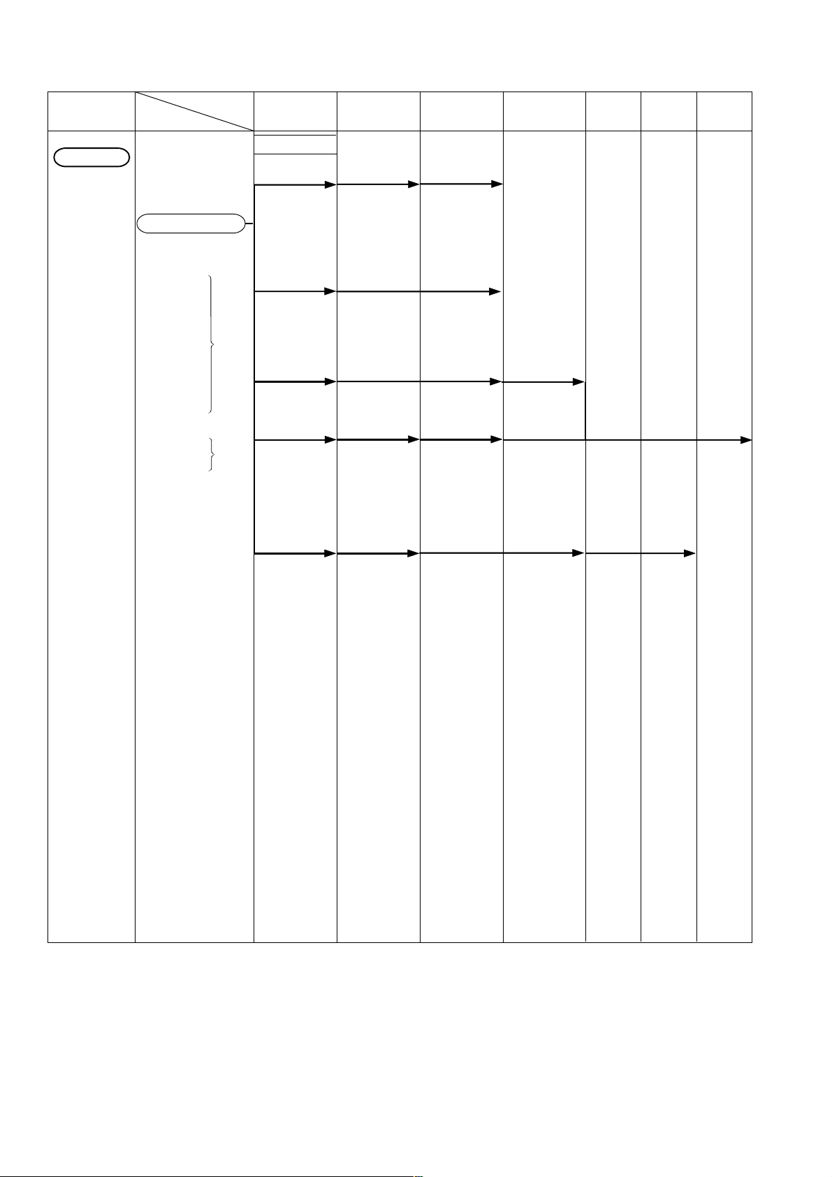
13. STANDARD REPAIR TIME (UNIT) SCHEDULES
MODEL 10 20 30 40 60 70 min.
Fixed
Variable
50
Work Flow
C 10FCD
General Assembly
Fixed Cost
Rear Cover
Handle Cover
Lever
PC-Guard
Handle
Chip Deflector
Connector Box
Cover
Connector Box
Switch
Power Cable
Other 20min.
0 min.
10 min.
Rear Cover
V-Belt
Connector Box
Cover
Pulley (B)
Handle Cover
Switch
Switch Lock
Spring
Carbon Brush
Lever
PC-Guard
Connector Box
Controller (R)
Power Cable
Spring
Bracket Stop
Bracket Stop
Compression
Spring
Gear Box
Gear Shaft
Ball Bearing
607
Ball Bearing
6001
Handle
Pulley (A)
Armature Ass'y
Cutter Shaft
Ball Bearing
6003
Helix Gear
Ball Bearing
608
Stator
Housing Ass'y
Arm
Fence
Clamp Lever
Locating Bar
Chip Deflector
Spring Plate
Center Shaft
Pivot Shaft
Torsion Spring
Base
Table
Angle
Regulator
--- 32 ---

Assembly Diagram for C 10FCD
--- 33 ---

MOTOR ASS'Y
C 10FCD
HOLDER ASS'Y
--- 34 ---

VISE ASS'Y
C 10FCD
--- 35 ---

PARTS
ITEM
1
CODE NO. DESCRIPTION
No.
1 311-096 CORD GUARD 1
2 317-546 POWER CABLE 1
3 317-547 HANDLE COVER 1
4 311-070 CORD CLAMP 1
5 317-548 TAPPING SCREW D4X12 2
6 949-780 HEX. SOCKET HD. BOLT M8X35 (10 PCS.) 3
7 317-549 HANDLE 1
8 317-550 LOCKING CABLE TIE 2
9 317-551 TAPPING SCREW D4X25 3
10 311-106 SPRING 1
11 317-552 SWITCH LOCK 1
12 311-103 TRUSS HD. TAPPING SCREW D4X12 1
13 317-553 SWITCH 1
14 949-271 MACHINE SCREW M8X20 (10 PCS.) 1
15 949-556 NUT M6 (10 PCS.) 1
16 950-094 HEX. SOCKET SET SCREW M6X20 1
17 968-247 HEX. SOCKET SET SCREW M6X10 2
18 317-554 INTERNAL WIRE 1
19 317-555 FLAT WASHER M13 1
20 317-556 MAGNET 1
21 317-557 PULLEY (A) 1
22 317-558 FLAT WASHER 1/4"X3/4" 1
23 949-613 BOLT M6X16 (10 PCS.) 1
24 317-559 V-BELT 1
25 317-560 WIRE PROTECTOR 1
26 317-561 CONNECTOR BOX 1
27 317-562 PICK UP 1
28 317-563 CONNECTOR BOX COVER 1
29 995-062 TAPPING SCREW (W/WASHER) D4X16 3
30 317-564 REAR COVER 1
31 949-239 MACHINE SCREW M5X16 (10 PCS.) 3
32 317-565 CONTROLLER (R) 1
33 317-566 TAPPING SCREW D4X16 3
34 317-567 ROUND WASHER HD. SCREW M5X8 2
35 607-ZZM BALL BEARING 607ZZMC2PS2S 1
36 317-569 GEAR SHAFT 1
37 317-570 PARALLEL KEY 4X4X20 1
38 600-1VV BALL BEARING 6001VVCMPS2L 1
39 317-571 PULLEY (B) 1
40 317-572 FLAT WASHER 1
41 314-519 NUT CHUCK M8 1
42 949-239 MACHINE SCREW M5X16 (10 PCS.) 3
43 317-573 GEAR BOX 1
44 317-574 PARALLEL KEY 4X4X8 1
45 317-575 BALL BEARING 6003LLU 1
46 317-576 CUTTER SHAFT 1
47 317-577 HELIX GEAR 1
48 317-578 C-RING 1
49 608-VVM BALL BEARING 608VVMC2EPS2L 1
50 314-980 TRUSS HD. STEP SCREW M6X12 1
51 317-579 TRUSS HD. ROUND NECK SCREW M6X10 1
----
99
: ALTERNATIVE PARTS
*
--- 36 ---
NO.
USED
C 10FCD
REMARKS

PARTS
ITEM
* 65 317-590 MOTOR ASS'Y 115V (UL) 1 INCLUD.142-158
* 65 317-591 MOTOR ASS'Y 115V (CSA) 1 INCLUD.142-158
CODE NO. DESCRIPTION
No.
52 317-580 LEVER 1
53 317-505 FLAT WASHER M6 1
54 317-582 COUNTER HD. SCREW M6X16 1
55 317-583 COLLAR 1
56 317-584 PC-GUARD 1
57 314-987 SPRING GUARD 1
58 311-036 RIVET 3/16"X17/32" 1
59 317-585 BUMPER 1
60 317-586 COUNTER HD. SCREW M5X12 1
61 317-587 CUTTER SHAFT GUARD 1
62 314-522 SPECIAL NUT CHUCK M6 1
63 317-588 SHAFT SLEEVE
64 317-589 TORSION SPRING 1
66 317-600 SPRING 1
67 317-601 BRACKET STOP 1
68 317-602 E-RING 1
69 311-016 CAP RUBBER 1
70 317-362 SCREW 1
71 317-363 COMPRESSION SPRING 1
72 317-364 CLAMP LEVER 1
73 317-365 HANDLE COLLAR 1
74 317-603 WASHER 1
75 317-604 NUT CHUCK M10 1
76 317-603 WASHER 1
77 317-606 PIVOT SHAFT 1
78 317-607 LOCATING BAR 1
79 317-608 ANGLE REGULATOR 1
80 317-609 SET BOLT 1
81 317-610 BRACKET STOP 1
82 317-611 COMPRESSION SPRING 1
83 317-612 PLUNGER HANDLE 1
84 949-236 MACHINE SCREW M5X10 (10 PCS.) 2
85 317-613 NEEDLE POINTER (L-SIDE) 1
86 949-822 HEX. SOCKET HD. BOLT M5X35 (10 PCS.) 1
87 317-614 NEEDLE POINTER (R-SIDE) 1
88 949-454 SPRING WASHER M5 (10 PCS.) 1
89 317-615 NUT CHUCK M5 1
90 311-042 DRIVE SCREW D2.3X5 2
91 317-616 TILTING SCALE 1
92 317-617 PLATE COVER 1
93 317-618 BOLT (LEFT HAND) M8X25 1
94 317-619 BLADE WASHER M30 1
95 317-428 ARBOR COLLAR 2
96 317-620 COLLAR D25.4 1
97 949-239 MACHINE SCREW M5X16 (10 PCS.) 2
98 317-621 CHIP DEFLECTOR 1
99 317-622 PIVOT SHAFT 1
100 949-676 BOLT M6X20 (10 PCS.) 2
101 949-556 NUT M6 (10 PCS.) 2
: ALTERNATIVE PARTS
*
--- 37 ---
NO.
USED
REMARKS
C 10FCD
----
1
99

PARTS
ITEM
1
CODE NO. DESCRIPTION
No.
102 314-519 NUT CHUCK M8 1
103 311-047 FLAT WASHER M8 1
104 949-556 NUT M6 (10 PCS.) 1
105 317-623 HEX. SOCKET SET SCREW M6X25 1
106 968-247 HEX. SOCKET SET SCREW M6X10 1
107 311-108 HEX. BOLT M10X65 1
108 317-624 TABLE 1
109 949-216 MACHINE SCREW M4X10 (10 PCS.) 4
110 317-625 TABLE INSERT 1
111 317-626 WASHER
112 317-627 FLAT WASHER 1/4"X5/8" 1
113 317-628 HEX. BOLT (W/WASHER) M6X20 1
114 317-628 HEX. BOLT (W/WASHER) M6X20 2
115 317-630 SPRING PLATE 1
116 317-631 MITER HANDLE 1
117 317-632 HEX. SOCKET HD. BOLT M8X45 3
118 317-633 FENCE 1
119 317-634 EXTENSION STAY 1
120 317-635 BASE 1
121 317-636 TAPPING SCREW D5X10 1
122 317-353 FOLLOWER PLATE 1
123 949-236 MACHINE SCREW M5X10 (10 PCS.) 2
124 317-637 CLAMP BOLT M5X15 1
125 949-555 NUT M5 (10 PCS.) 4
126 949-236 MACHINE SCREW M5X10 (10 PCS.) 1
127 317-638 ANGLE POINTER 1
128 317-639 SLIDE PLATE 3
129 317-640 CENTER SHAFT 1
130 NAME PLATE 1
131 HITACHI LABEL 1
132 310-871 CAUTION LABEL (E) 1
133 310-870 WARNING LABEL (A) 1
134 317-642 VISE ASS'Y (FOR VERTICAL) 1 INCLUD.135-140
135 968-247 HEX. SOCKET SET SCREW M6X10 1
136 317-643 SUPPORT 1
137 317-644 SCREW BAR 1
138 317-645 VISE BEARING 1
139 317-646 FLANGE 1
140 317-647 BUSHING 1
141 317-641 INSULATING SLEEVE 2
142 967-377 HEX. SOCKET SET SCREW M5X8 2
143 880-734
144 317-592 HOUSING ASS'Y 1 INCLUD.145
145 314-577 BEARING BUSHING 1
146 997-841
147 314-586 BRUSH HOLDER 2
148 311-089 CARBON BRUSH 2
149 314-583 BRUSH CAP 2
150 317-593 INTERNAL WIRE 1
151 317-594 STATOR 115V 1
152 317-595 MACHINE SCREW M5X60 2
----
99
MACHINE SCREW (W/WASHERS) M5X25 (BLACK)
MACHINE SCREW (W/WASHERS) M5X50 (BLACK)
: ALTERNATIVE PARTS
*
NO.
USED
2
2
--- 38 ---
C 10FCD
REMARKS

PARTS
ITEM
CODE NO. DESCRIPTION
NO.
153 317-596 FLOW GUIDE 1
154 317-597 ARMATURE ASS'Y 115V 1 INCLUD.155-157
155 317-598 PLAIN WASHER 1
156 620-0VV BALL BEARING 6200VVCMPS2S 1
157 620-2VV BALL BEARING 6202VVCMPS2S 1
158 317-599 ARM 1
159 317-824 COVER PLATE 1
160 317-825 RIVET D3.2X8.1 2
NO.
USED
C 10FCD
REMARKS
: ALTERNATIVE PARTS
*
--- 39 ---
----
1
99

STANDARD ACCESSORIES
ITEM
CODE NO. DESCRIPTION
NO.
701 311-128 TCT SAW BLADE 255MM-D15.88 HOLE-NT24 1
702 311-013 WRENCH 1
703 311-034 DUST BAG 1
USED
NO.
C 10FCD
REMARKS
OPTIONAL ACCESSORIES
ITEM
901 976-472
902 977-671
903 976-473 TCT SAW BLADE 255MM-D15.9 HOLE 1
904 977-673
905 317-542 HOLDER ASS'Y 1 INCLUD.906-910
906 317-654 STOCK STOP 1
907 317-375 WING BOLT 1/4"X3/4" 1
908 317-655 LOCK SUPPORT ROD 2
909 317-656 EXTENSION WING 2
910 949-271 MACHINE SCREW M8X20 (10 PCS.) 2
911 317-541 VISE ASS'Y (FOR LATERAL) 1 INCLUD.912-921
912 317-648 SCREW BAR 1
913 317-649 VISE BEARING 1
914 949-515 ROLL PIN D6X30 (10 PCS.) 1
915 317-650 CLUTCH 1
916 317-629 SET PLATE 1
917 311-126 WASHER 3/16"X1/2" 1
918 317-503 MACHINE SCREW (W/WASHER) M5X10 1
919 317-652 SUPPORT 1
920 949-518 ROLL PIN D3X18 (10 PCS.) 1
921 317-653 KNOB 1
CODE NO. DESCRIPTION
NO.
TCT SAW BLADE CROSS-CUT 255MM-D15.9 HOLE
TCT SAW BLADE (A) 255MM-D15.88 HOLE-NT24
TCT SAW BLADE (B) 255MM-D15.88 HOLE-NT60
NO.
USED
1
1
1
REMARKS
Printed in Japan
(99120 N)
----
1
99
: ALTERNATIVE PARTS
*
--- 40 ---
 Loading...