

HITACHI C 10FCB User guide
MODEL
C 10FCB
POWER TOOLS
TECHNICAL DATA
C
COMPOUND SAW
C 10FCB
AND
SERVICE MANUAL
LIST No. E931
Apr. 2001
SPECIFICATIONS AND PARTS ARE SUBJECT TO CHANGE FOR IMPROVEMENT

CONTENTS
Page
1. PRODUCT NAME......................................................................................................................... 1
2. MARKETING OBJECTIVE ........................................................................................................... 1
3. APPLICA TIONS........................................................................................................................... 1
4. SELLING POINTS ........................................................................................................................ 1
4-1. Selling Point Descriptions ............................................................................................................ 2
5. SPECIFICATIONS ........................................................................................................................ 4
6. COMPARISONS WITH SIMILAR PRODUCTS ........................................................................... 5
7. PRECAUTIONS IN SALES PROMOTION ................................................................................... 6
7-1. Instruction Manual ....................................................................................................................... 6
8. ADJUSTMENT AND OPERATIONAL PRECAUTIONS.............................................................. 7
8-1. Cutting A Groove on The Table Insert .......................................................................................... 7
8-2. Confirmation of Saw Blade Lower Limit Position ......................................................................... 7
8-3. How to Use The Vise Assembly ................................................................................................... 8
8-4. Confirmation for Use of Sub Fence ............................................................................................. 8
8-5. Cutting Operation......................................................................................................................... 9
9. ADJUSTMENT OF COMPONENTS........................................................................................... 11
9-1. Bevel Angle Adjustment ................................................................................................................11
10. PACKING....................................................................................................................................11
11. PRECAUTIONS IN DISASSEMBLY AND REASSEMBLY.........................................................12
11-1. Disassembly............................................................................................................................... 12
11-2. Reassembly ............................................................................................................................... 17
11-3. Wiring Diagram .......................................................................................................................... 18
11-4. Lead Wire Precautions............................................................................................................... 19
11-5. No-load Current.......................................................................................................................... 20
11-6. Reassembly Requiring Adjustment............................................................................................ 20
11-7. Lubrication.................................................................................................................................. 21
11-8. Product Precision....................................................................................................................... 21
1 1-9. Tightening Torque....................................................................................................................... 22
12. REPAIR GUIDE ......................................................................................................................... 23
13. STANDARD REPAIR TIME (UNIT) SCHEDULES .....................................................................27
Assembly Diagram for C 10FCB
1. PRODUCT NAME
Hitachi Compound Saw, Model C 10FCB
2. MARKETING OBJECTIVE
The Model C 10FCB has been newly developed as a successor of the current Models C 10FC, C 10FC2 and
C 10FCA (REXON's OEM products) intended to be manufactured in the factory of Hitachi Koki Group (HKF) to
keep high quality and to adopt Hitachi Koki's original design. Vigorous sales promotion and market share
increases are anticipated with the introduction of the new Model C 10FCB. Although the Model C 10FCB is of the
same construction as the current models basically, the Model C 10FCB employs additional functions including the
following:
Capable of cutting both 2 x 6 and 4 x 4 materials at the right angle at a time without the use of a plate
Capable of narrowing the clearance between the fences thanks to the adoption of the rotary sub fence
3. APPLICA TIONS
Cutting various types of wood workpieces
Cutting workpieces of plywood, decoration panels, soft fiberboard and hard board
Cutting aluminum sashes
4. SELLING POINTS
Capable of cutting both 2 x 6 and 4 x 4
materials at the right angle at a time
without the use of a plate
Lightweight design: 14 kg
Left bevel cutting
Newly adopted rotary sub fence
(capable of narrowing the
clearance between the fences)
Compound miter and
left bevel cutting
Safety (lock-off) switch
(only for USA, Canada)
Press cutting
Equipped with debris guard to
restrict dispersion of chips for
enhanced safety in operation
--- 1 ---
Right
Left
Miter cutting
Convenient miter with
angle setting mechanism
4-1. Selling Point Descriptions
(1) Press cutting
Table 1
Maker
Model
Max. cutting
dimension
Height x Width
(H x W)
Press cutting with the head swiveling enables cutting square workpieces as large as shown in Table 1 in a single
sawing operation. (See Fig. 1.)
(2) Miter cutting facility
Maker
Model
Max. cutting
dimension
Right 60˚
Height x Width
(H x W)
Right and left 45˚
Height x Width
(H x W)
59 x 144 (2-5/16" x 5-21/32")
89 x 101 (3-1/2" x 3-31/32")
Table 2
HITACHI
C 10FCB
HITACHI
C 10FCB
59 x 72
(2-5/16" x 2-13/16")
59 x 102
(2-5/16" x 4")
(Unit: mm)
(Unit: mm)
Workpiece
Workpiece
Width (W)
Height (H)
Fig. 1
Width (W)
Height (H)
45˚ right and
left (60˚ right)
Fig. 2
By turning the table to the right or left as desired, the Model C 10FCB is capable of miter cutting of up to 45˚ to the
left, or 60˚ to the right. The miter angle setting mechanism enables easy cutting-angle setting.
(3) Left bevel cutting facility
Table 3
Maker
Model
Max. cutting
dimension
Left bevel 45˚
Height x Width
(H x W)
By inclining the saw blade section (head) on its swivel mounting,
bevel cutting of up to a maximum of 45˚ to the left can be obtained.
(When the machine is shipped from the factory, the swivel stoppers
of the head are precisely adjusted for 0˚ and 45˚ [for further details,
please refer to Paragraph 9-1, Bevel Angle Adjustment].)
41 x 144 (1-5/8" x 5-21/32")
HITACHI
C 10FCB
(Unit: mm)
(Left)
Bevel cutting
Fig. 3
Width (W)
45˚
Height (H)
--- 2 ---
(4) Compound cutting through use of miter and bevel cutting functions
Table 4
(Unit: mm)
Maker
Model
Max. cutting
HITACHI
C 10FCB
45˚ (Left)
dimension
Left bevel 45˚
Right/Left miter 45˚
41 x 102 (1-5/8" x 4")
45˚
(Right or left)
Height x Width
(H x W)
* When the saw blade section (head) is inclined 45˚ to the
left, the maximum possible angle setting of the table is
By turning the table to the right or left and inclining the saw
blade section (head) to the left, the Model C 10FCB is
restricted to 45˚ to either the left or right.
Fig. 4
capable of compound cutting (bevel and miter, see Fig. 4) of
workpieces with the maximum dimension shown in Table 4.
(5) Equipped with debris guard to restrict dispersion of chips for enhanced safety in operation
A debris guard has been adopted to prevent wood chips from adhering to the saw blade at the end of the
cutting operation. The debris guard tilts together with the saw blade during bevel cutting, thereby enhancing
Width (W)
Height (H)
safe operation.
(6) Lightweight design
14 kg in weight, for easy transport in a workshop
--- 3 ---
5. SPECIFICATIONS
Maximum
cutting
dimentions
Height x
Width
(H x W)
0˚ (Right angle)
Miter right/left 45˚
Bevel left 45˚
Miter right/left 45˚
+
59 mm (2-5/16") x 144 mm (5-21/32")
89 mm (3-1/2") x 101 mm (3-31/32")
59 mm (2-5/16") x 102 mm (4") [Right 60˚: 59 mm (2-5/16") x 72 mm (2-13/16")
41 mm (1-5/8") x 144 mm (5-21/32")
41 mm (1-5/8") x 102 mm (4")
Bevel left 45˚
Miter cutting ranges Right 0˚ --- 60˚, Left 0˚ --- 45˚
Bevel cutting ranges Left 0˚ --- 45˚
Compound (miter + bevel)
cutting ranges
Angle stopper positions
Miter: right and left 0˚ --- 45˚, Bevel: left 0˚ --- 45˚
Right and left 0˚, 15˚, 22.5˚, 31.6˚, 35.3˚, 45˚, Right 60˚ (for USA, CAN)
Right and left 0˚, 15˚, 22.5˚, 30˚, 45˚, Right 60˚
Applicable saw blade
255 mm (10") external dia.
USA/CAN
Asia/China
Saw blade bore
25.4 mm (1")15.9 mm (5/8")
USA/CAN Europe/China
Safety (lock-off) switch
Europe
30 mm (1-11/64")
Asia/Australia, etc.
]
Australia
New Zealand
25.4 mm (1") and
30 mm (1-11/64")
Not providedNot providedProvided
Not provided Not providedProvidedSaw cover lock
Power source type and voltage AC single phase 50/60 Hz, 110V, 115 V, 220V --- 240V
Type of motor
Full-load current
No-load rotation speed
Max. output
Main body dimensions
(Width x Depth x Height)
Weight
Coating
Packaging
Cord
AC single phase commutator series motor
110 V --- 115 V: 15 A 220 V: 7.8 A 230 V: 7.5 A 240 V: 7.2 A
4,900/min.
2,300 W
547 mm x 592 mm x 581 mm (21-17/32" x 23-5/16" x 22-7/8")
14 kg (31 Ibs.), gross weight 21 kg (46.5 Ibs.)
Metallic silver green
Corrugated cardboard box
Type: 2-conductor cabtire cable
Length: 2.2 m (7.2 ft)
255 mm (10") TCT saw blade (24 teeth, Code No. 318963)
•••••••••••••••
for wood cutting (except for CHN)
255 mm (10") TCT saw blade (100 teeth, Code No. 318964)
Standard accessories
•••••••••••••••
255 mm (10") TCT saw blade (30 teeth, Code No. 319107)
•••••••••••••••
for aluminum cutting (for CHN)
for wood cutting (for AUT, GBR, FRA, HOL,
BEL,ESP, SUI, ITA, NOR,
SWE, DEN, FIN)
Dust bag
Vise ass'y
Box wrench 10 mm
Holder
Stopper
Optional accessories
255 mm (10") TCT saw blade (60 teeth, Code No. 976472)
•••••••••••••••
for normal cutting
255 mm (10") TCT saw blade (100 teeth, Code No. 319658)
•••••••••••••••
for aluminum cutting (except for CHN)
--- 4 ---
6. COMPARISONS WITH SIMILAR PRODUCTS
Maker/Model
Item
0˚ (Right angle)
Max.
cutting
dimensions
Height
x Width
(H x W)
Miter cutting ranges
Bevel cutting ranges
Compound (miter + left bevel)
cutting ranges
Angle stopper position
Saw blade outer diameter (mm)
Power input (W)
No-load revolution (/min.)
Motor
Max. output (W)
Insulation structure
Base size
Width x Depth (mm)
Debris guard
Dust bag size (mm)
Main unit dimensions
Width x Depth x Height (mm)
Product weight (kg)
Standard accessories
Miter right/left 45˚
Bevel left 45˚
Miter right/left 45˚
+
Bevel left 45˚
HITACHI
C 10FCB
59 mm x 144 mm
(2-5/16" x 5-21/32")
89 mm x 101 mm
(3-1/2" x 3-31/32")
59 mm x 102 mm
(2-5/16" x 4")
Right 60˚
59 mm x 72 mm
(2-5/16" x 2-13/16")
41 mm x 144 mm
(1-5/8" x 5-21/32")
41 mm x 102 mm
(1-5/8" x 4")
Right 0˚--- 60˚
Left 0˚--- 45˚
Left 0˚--- 45˚
Miter: Right and left
0˚ - -- 45˚
Bevel: Left 0˚ - -- 45˚
Right and left 0˚, 15˚,
22.5˚, 31.6˚, 45˚
Right 60˚
255 (10")
1,640
4,900
2,300
Double insulation
525 x 137
(20-21/32" x 5-13/32")
Provided (fixed)
250 x 160
(9-27/32" x 6-5/16")
547 x 592 x 581
(21-17/32" x 23-5/16" x 22-7/8")
14 (31 lbs.)
255 mm (10") TCT saw
•
blade (24 teeth) for
wood cutting
• Dust bag
• Vise ass'y
• Box wrench 10 mm
• Holder
• Stopper
HITACHI
C 10FC2/C 10FC
67 mm x 146 mm
(2-5/8" x 5-3/4")
89 mm x 92 mm
(3-1/2" x 3-5/8")
[with aux. board width
17 mm (11/16")]
70 mm x 89 mm
(2-3/4" x 3-1/2")
Right 60˚
70 mm x 73 mm
(2-3/4" x 2-7/8")
44 mm x 130 mm
(1-3/4" x 5-1/8")
44 mm x 89 mm
(1-3/4" x 3-1/2")
Right 0˚--- 60˚
Left 0˚--- 45˚
Left 0˚--- 45˚
Miter: Right and left
0˚ - -- 45˚
Bevel: Left 0˚ - -- 45˚
Right and left 0˚, 15˚,
22.5˚, 31.6˚, 45˚
Right 60˚
255 (10")
1,640
4,900
2,200
Double insulation
525 x 150
(20-11/16" x 5-29/32")
Provided (fixed)
300 x 190
(11-13/16" x 7-15/32")
535 x 600 x 489
(21-1/16" x 23-1/2" x 19-1/4")
14.5 (32 lbs.)
•
255 mm (10") TCT saw
blade (24 teeth) for
wood and aluminum
cutting
• Dust bag
• Vise ass'y
• Wrench
Z
70 mm x 146 mm
(2-3/4" x 5-3/4")
70 mm x 105 mm
(2-3/4" x 4-1/8")
44 mm x 146 mm
(1-3/4" x 5-3/4")
44 mm x 105 mm
(1-3/4" x 4-1/8")
Right and left 0˚--- 45˚
Left 0˚--- 45˚
Miter: Right and left
0˚ - -- 45˚
Bevel: Left 0˚ - -- 45˚
Right and left 0˚, 15˚,
22.5˚, 30˚, 45˚
255 (10")
------
4,900
------
Double insulation
455 x 125
(17-15/16" x 4-15/16")
None
300 x 190
(12-19/32" x 7-15/32")
455 x 595 x 535
(17-29/32" x 23-13/32" x 21")
22 (49 lbs.)
• 255 mm (10")
combination saw
blade (104 teeth)
• Dust bag
•
Vise ass'y (horizontal type)
• Holder ass'y
• Wrench
C
69 mm x 130 mm
(2-3/4" x 5-1/8")
69 mm x 92 mm
(2-3/4" x 3-5/8")
35 mm x 130 mm
(1-3/8" x 5-1/8")
35 mm x 92 mm
(1-3/8" x 3-5/8")
Right 0˚--- 52˚
Left 0˚--- 45˚
Left 0˚--- 45˚
Miter: Right and left
0˚ --- 45˚
Bevel: Left 0˚ - -- 45˚
Right and left 0˚, 15˚,
22.5˚, 30˚, 45˚
Right 52˚
255 (10")
------
4,600
------
Double insulation
460 x 135
(18-3/32" x 5-5/16")
None
300 x 150
(11-13/16" x 5-15/16")
476 x 530 x 532
(18-3/4" x 20-7/8" x 20-15/16")
11 (24.2 lbs.)
•
255 mm (10") TCT
saw blade
• Dust bag
• Auxiliary plate
•
13 mm socket wrench
• Wrench
• Triangular rule
Optional accessories
•
255 mm (10") TCT saw
blade (60 teeth) for
normal cutting
•
255 mm (10") TCT saw
blade (100 teeth) for
aluminum cutting
• Holder ass'y
•
255 mm (10") TCT saw
blade (70 teeth) for
normal cutting
--- 5 ---
• Safety goggles
7. PRECAUTIONS IN SALES PROMOTION
In the interest of promoting the safest and most efficient use of the Model C 10FCB Compound Saw by all of our
customers, it is very important that at the time of sale the salesperson carefully ensures that the buyer seriously
recognizes the importance of the contents of the Instruction Manual, and fully understands the meaning of the
precautions listed on the various Caution Plates attached to each machine.
7-1. Instruction Manual
Although every effort is made in each step of design, manufacture and inspection to provide protection against
safety hazards, the dangers inherent in the use of any power saw cannot be completely eliminated. Accordingly,
general precautions and suggestions for the use of electric power tools, and specific precautions and suggestions
for the use of the compound saw are listed in the Instruction Manual to enhance the safe, efficient use of the tool
by the customer. Salespersons must be thoroughly familiar with the contents of the Instruction Manual to be able
to offer appropriate guidance to the customer during sales promotion.
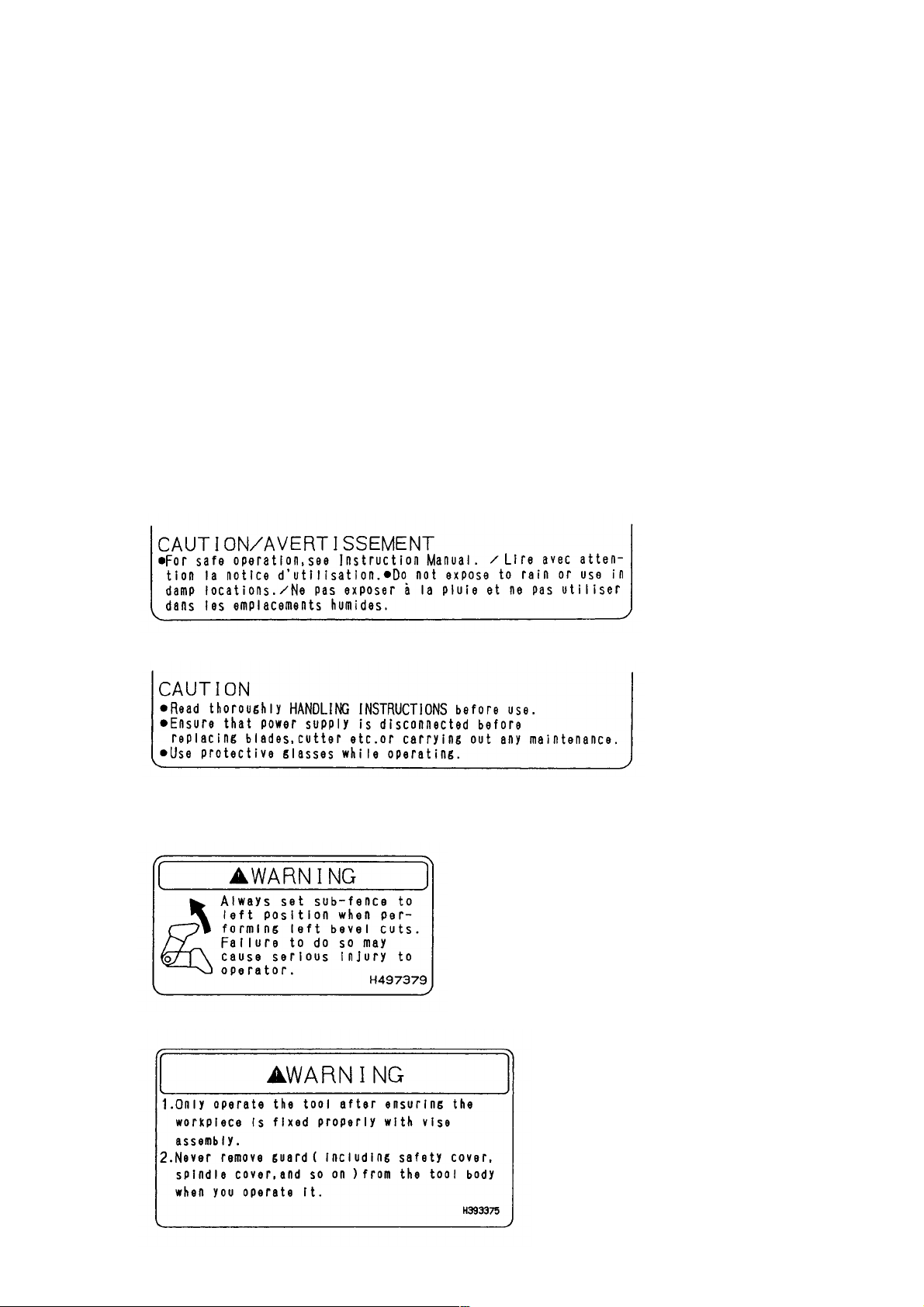
(1) Precautions on the name plate
Each Model C 10FCB is furnished with a Name Plate that lists the following precautions.
For the U.S.A. and Canada only
Except the U.S.A. and Canada
Instruct the customer to thoroughly read the Instruction Manual prior to attempting to operate the machine.
(2) Caution plate (A)
(3) Caution plate (B)
--- 6 ---
(4) Caution plate (C)
For the U.S.A. and Canada only
The caution plate (C) specified by the UL is affixed on the upper right-hand portion of the gear case. Please
instruct users to strictly observe the contents 1 to 9 in the caution plate (C) shown above.
8. ADJUSTMENT AND OPERATIONAL PRECAUTIONS
8-1. Cutting A Groove on The Table Insert
A groove has to be cut in the table insert, before starting operation.
Secure a piece of wood about 5-1/2" (140 mm) wide to the table with
the vise assembly, to prevent the breakage of the table insert. After the
switch has been turned on and the saw blade has reached maximum
speed, slowly lower the handle to cut a groove on the table insert.
CAUTION: Do not cut the groove too quickly; otherwise the
table insert might become damaged.
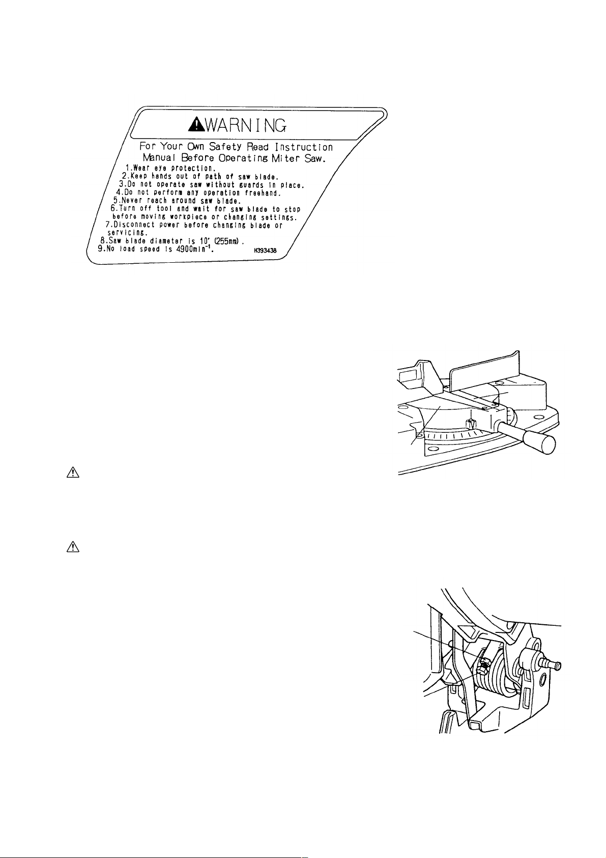
8-2. Confirmation of Saw Blade Lower Limit Position
WARNING: To prevent an accident or personal injury, always turn off the trigger switch and
disconnect the power plug from the receptacle before adjustment.
Check that the saw blade can be lowered 1-5/8" to 1-21/32" (41 mm
to 42 mm) below the table insert. If necessary, adjust as follows:
(1) Loosen the 8 mm lock nut on the 8 mm depth adjustment screw.
(2) Turn the 8 mm depth adjustment screw as necessary to set the
Turn table
Fig. 5
8 mm lock nut
Table
insert
lower limit position. The saw blade goes up when the 8 mm
depth adjustment screw is turned counterclockwise and down
when it is turned clockwise.
(3) Once the adjustment is complete, fully tighten the 8 mm lock nut.
NOTE: Before tightening the 8 mm lock nut, confirm that the saw blade is adjusted so that it will not cut into the
table.
--- 7 ---
8 mm depth
adjustment
screw
Fig. 6
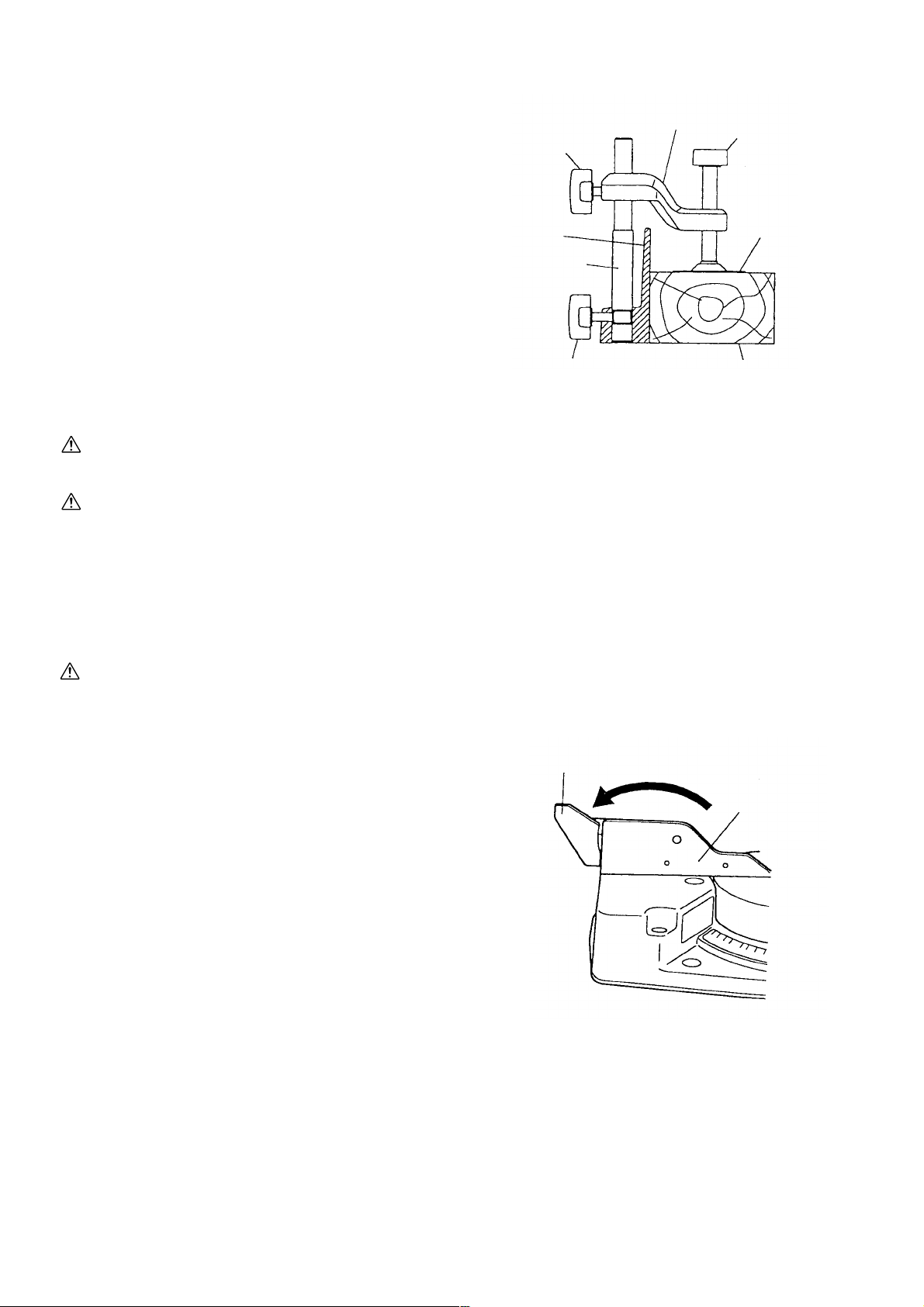
8-3. How to Use The Vise Assembly
(1) The vise assembly can be mounted on either the left fence
(fence (B)) or the right fence (fence (A)) by loosening
6 mm wing bolt (A).
(2) The screw holder can be raised or lowered according to the
height of the workpiece by loosening 6 mm wing bolt (B).
After the adjustment, firmly tighten 6 mm wing bolt (B) and
fix the screw holder.
(3) Turn the upper knob and securely fix the workpiece in
position (Fig. 16).
WARNING: Always firmly clamp or vise to secure the workpiece to the fence; otherwise the
workpiece might be thrust from the table and cause bodily harm.
CAUTION: Always confirm that the motor head (see Fig. 1) does not contact the vise assembly when
it is lowered for cutting. If there is any danger that it may do so, loosen the 6 mm wing
bolt (B) and move the vise assembly to a position where it will not contact the saw blade.
6 mm wing
bolt (B)
Fence
Vise shaft
6 mm wing
bolt (A)
Screw holder
Fig. 7
Knob
Vise plate
Workpiece
8-4. Confirmation for Use of Sub Fence
WARNING: In the case of left bevel cutting, turn the sub fence counterclockwise. Unless it is turned
counterclockwise, the main body or saw blade may contact the sub fence, resulting in an
injury.
Sub fence
In the case of direct angle cutting and angle cutting, use the
sub fence. Then, you can realize stable cutting of the
material with a wide back face. In the case of left bevel
cutting, raise the sub fence up as illustrated in Fig. 9 and
then turn it counterclockwise.
Turn.
Fence (B)This power tool is equipped with a sub fence. (See Fig. 1.)
Fig. 8
--- 8 ---
8-5. Cutting Operation
(1) Cutting efficiency will be reduced if a dull saw blade is used, if an excessively long extension cord is used, or if
the wire gauge of the extension cord is too small. (For details on extension cords, please refer to the
Instruction Manual.) This is particularly important when cutting materials with dimensions which are at or near
the maximum capacity for the machine.
(2) The customer should be advised to thoroughly inspect the workpiece to ensure that there are no metallic
objects (nails in particular), sand, or other foreign matter in or on the workpiece. Saw blade contact with such
foreign matter will not only shorten the service life of the saw blade, but could cause serious accident. Should
the saw blade tips be broken off, the tips may fly toward the operator.
(3) Press cutting
Like the Model C 10FC2, the Model C 10FCB can be used for press cutting of workpieces up to 59 mm x
144 mm (2-5/16" x 5-21/32") in a single operation by simply pushing the saw blade section (head) downward.
The customer should be cautioned that excessive pressure on the handle will not increase the cutting speed.
On the contrary, excessive pressure may result in reduced cutting efficiency (irregular or rough cutting of the
workpiece), and could also cause overload and subsequent burnout of the motor.
On completion of the cutting operation, turn the switch OFF and wait for the saw blade to come to a complete
stop before raising the saw blade section (head) to its original position. Raising the saw blade section (head)
while the saw blade is rotating may cause unwanted cutting marks on the workpiece.
Techniques to avoid unwanted cutting marks
Uneven and unwanted cutting marks can be avoided throughout the cutting operation by gently and smoothly
pressing down on the handle, so that the entire cutting operation is accomplished in a single uninterrupted
motion.
(4) Miter cutting
Miter cutting is accomplished by turning the table. (For details, please refer to the Instruction Manual.)
(5) Bevel cutting
Bevel cutting of 0 --- 45˚ to the left is accomplished by inclining the saw blade section (head). (For details,
please refer to the Instruction Manual.)
[Caution] When the workpiece is secured on the left side, the
cut-off portion comes to rest on the side of the saw
blade as illustrated in Fig. 8. If the handle is raised
Fixed-side workpiece
Cut-off-side
workpiece
before the saw blade rotation comes to a complete
stop, there is a chance that the cut-off portion of the
workpiece could become jammed against the saw
blade, causing a hazardous condition. Instruct the
customer to ensure without fail that the saw blade
comes to a complete stop before attempting to raise
the handle.
--- 9 ---
Saw blade
Fig. 9
 Loading...