

Page 1

*372188*
372190
PD 22
Operating instructions
en
Page 2

7
10
3
2
4
8
56
1 9
I
x
-
N
E
M
R
E
S
A
L
PD 22
+
x
-
+
I
PD 22
L
ASE
R
M
EN
x
-
+
I
2
3
1
Page 3
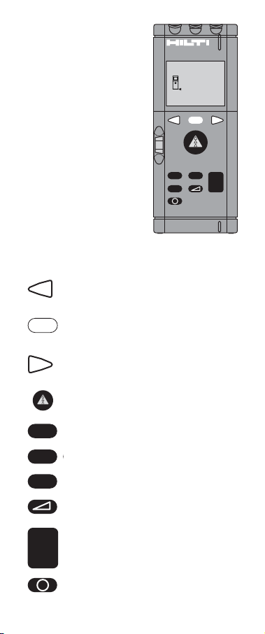
Recall previous measurements (max. 3)
Scroll through active menu
Show menu / exit from menu
(rEF/nor/CONSt/Light/dELAY/bEEP/UNIT).
Recall previous measurements (max. 3)
Scroll through active menu
Measure distance or start tracking.
Addition
Subtraction
Multiplication
Pythagoras (calculates opposite side of
right-angled triangle)
Execute calculation or reset display
Switch range meter on / off
Button functions
Display
Select menu
Measure
Calculate
Switch on / off
PD 22
LASER
MENU
x
–
x
MENU
x
+
=
-
I
=
I
Page 4
The PD22 at a glance
3
- - -
x
-
+
I
2
1
I
x
-
+
N
E
M
R
E
S
A
L
PD 22
I
I
x
-
+
MEN
R
E
S
A
L
2
2
D
P
Page 5

0.1 - 30 m: 30 - 100 m:
P
D
2
2
L
A
S
E
R
M
E
N
x
-
+
I
x
-
+
I
+ x
–
I
ft in
+
m
ft in
–
m
ft in
x
m
ft in
m
s
MENU
P
D
2
2
L
A
S
E
R
M
E
N
3
m/m2/m
ft in
=
sq.ft /in
h!
=
a
rEF
nor
CONSt
Light
dELAY
bEEP
UNIT
+
–
+
nEAr/ FAr
–
+
0.000 ...
999.999m
–
+
OFF / ON / Auto
–
+
0/2/5/10/20 s
–
+
Auto/ON/OFF
–
+
m / in
–
Page 6

1
It is essential that the operating
instructions are read before the range
meter is operated for the first time.
Always keep these operating instructions
together with the range meter.
Ensure that the operating instructions are
with the range meter when it is given to
other persons.
Parts of the PD 22
1. Laser exit aperture
2. Control panel
3. Receiving lens
4. Plastic casing
5. Bubble level
6. Battery compartment
7. Folding spike
8. Two tripod mounting threads (standard
camera thread)
9. Graphical display
10. Four metal contact points for precise
measurement
Page 7

2
Contents
1. General information....................................4
1.1 Indication of important information .......4
1.2 Pictograms ............................................4
2. Description..................................................6
2.1 Function.................................................6
2.2 Items supplied .......................................6
3. Tools and accessories ................................6
4. Technical data.............................................7
5. Safety information ......................................9
5.1 Basic safety information ........................9
5.2 Intended use ..........................................9
5.3 Misuse ...................................................9
5.4 Latest technology ................................10
5.5 Proper organisation of the workplace ..10
5.5.1 Electromagnetic compatibility ....11
5.5.2 Laser classification.....................11
5.6 General safety precautions...................12
5.6.1 Electrical.....................................13
6. Before use.................................................13
6.1 Inserting new batteries.............................13
6.2 Menu selection and settings.....................14
6.2.1 rEF menu / reference edge..........14
6.2.2 nor menu / track menu ...............15
6.2.3 CONST menu / constants ...........15
6.2.4 Light menu / display
illumination.................................16
6.2.5 dELAY menu / self-timer.............16
6.2.6 dEEP menu / beep signal............17
6.2.7 UNIT menu / units of
measurement .............................17
7. Operation ..................................................18
7.1 Measuring distances............................18
7.2 Measuring using the spike...................19
7.2.1 Measuring from an inside corner
(e.g. corner of a room) ...............19
7.2.2 Measuring from an outside
corner.........................................20
Page 8

3
Contents
7.3 Measuring using the self-timer ............20
7.4 Measuring using target objects............21
7.5 Taking measurements from various
surfaces ...............................................21
7.5.1 Plants and trees..........................21
7.5.2 Rough surfaces ..........................22
7.6 Continuous distance measurement
(tracking) .............................................23
7.6.1 Continuous distance
measurement (“EAr”) .................23
7.6.2 Continuous distance
measurement (“FAr”) .................25
7.7 Calculation functions ...........................27
7.7.1 Addition / subtraction
(distance) ...................................27
7.7.2 Multiplication (areas /
volumes) ....................................28
7.8 Calculations using the Pythagoras
principle...............................................31
7.9 Calculations using constants ...............33
8. Symbols displayed....................................34
9. Testing and adjustment ............................35
10. Care and maintenance............................36
10.1 Cleaning and drying ...........................36
10.2 Storage ..............................................36
10.3 Transport ...........................................36
11. Disposal ..................................................37
12. Warranty .................................................38
13. FCC statement (applicable in US) ..........39
14. EC declaration of conformity ..................41
Page 9

4
1. General information
1. General information
1.1 Indication of important information
-NOTE-
This word indicates information intended to
help the user employ the product efficiently and
in a technically correct manner.
1.2 Pictograms
Symbols
Warning signs
General warning
Laser class 2
(Do not stare into the
beam!)
Read the operating
instructions before
use.
These numbers refer to the corresponding
illustrations. The illustrations can be found on
the fold-out cover pages. Keep these pages
open while studying the operating instructions.
In these operating instructions, the PD 22 laser
range meter is referred to as “the range meter”.
Page 10

5
1. General information
Location of identification data on the range
meter
The type designation and serial number can be
found on the rating plate on the range meter.
Make a note of this data in your operating
instructions and always refer to it when making
an enquiry to your Hilti representative or
service department.
Type : _____________
Serial no.:___________
Type: PD 22
319196
Made in Germany
Page 11

6
2. Description / 3. Tools and accessories
2. Description
2.1 Function
The red laser spot clearly identifies the target
from which the measurement is taken. The
range of the range meter depends on the
reflectance and finish of the target surface.
2.2 Items supplied
No. Qty. Designation
1 1 PD 22 laser range meter
2 2 Type AA batteries
3 1 Carrying case
4 1 Operating instructions
3. Tools and accessories
Target plate
PA 412
With two target surfaces of different colours:
- White side, when reflectance is too high.
- Brown side, when reflectance is too low.
Sighting glasses
PA 970
The laser sighting glasses improve visibility
of the laser target spot (by a factor of 4 - 5).
Tripod adaptor
PA 450
With fine adjustment of the X and Y axes for
setting up precisely on a tripod.
Telescopic sight
PA 421
For targeting objects precisely over long
distances and outdoors.
Page 12

7
4. Technical data
4. Technical data
Power supply
3 V DC
Battery type: AA (LR6, AM3, Mignon)
Standard: 2 alkaline primary cells
Optional. Rechargeable NiCd, NiMH
Battery status indicator
Warning symbol when battery voltage is
too low.
Measuring range
0.1 to over 100m (4 in to over 300 ft)
Typical measuring range without target
plate:
- Drywall panel, white 70m (210 ft)
- Concrete, dry 50m (150 ft)
- Brick, dry 50m (150 ft)
Maximum range depends on:
- Reflectance of the target surface
- Brightness of ambient light
Use the Hilti PA 412 target plate above
distances of 30 - 40 m if measurement is
impossible.
Accuracy
±2mm (±0.10 in) for typical individual
measurements
±3mm (±0.15 in) maximum **
** Due to atmospheric influences,
the range meter can be expected
to achieve an accuracy of ± (2mm
+ 30ppm) approx. ± 5mm at long
distances (100 m).
Smallest unit displayed
1mm (1/32 in)
Page 13

8
4. Technical data
Beam diameter
< 6mm @ 10m (< 0.2 in @ 30 ft)
< 30mm @ 50m (< 1.2 in @ 150 ft)
< 60mm @ 100m (< 2.4 in @ 300 ft)
Operating modes
Individual measurement
Continuous measurement
Calculation
Operating status indicator
Liquid crystal display indicating
individual operating modes and
operating status
Laser
Visible, 620-690nm, Laser class 2
(IEC825-1), class II (FDA21CFR), output
power:< 1mW
Automatic cut-out
Laser : 25 sec. Range meter: 5 min.
Battery life at 25º C [+77º F]
Max. number of measurements with
laser switched on for a duration of 10
seconds
Alkaline : 8000 - 9000
NiCd: 4000
NiMH: 6000
Operating temperature
-10º C ... +50º C (14º F ... 122º F)
Storage temperature
-30º C ... +70º C (-22º F ... 158º F)
Protection class
Dust and splash-proof, IP 54 as per
IEC529 standard
Page 14

9
4. Technical data / 5. Safety information
Mounting points
1/4” Whitworth internal thread, 1 on the
side and 1 on the underside (standard
camera tripod thread)
Weight
320 g (without batteries)
Dimensions
165 x 67x 47mm (6.5” x 2.6” x 1.8”)
5. Safety information
5.1 Basic safety information
In addition to the safety precautions listed in
the individual sections of these operating
instructions, the following points must be
strictly observed at all times.
5.2 Use as intended
The intended uses of the range meter include
the following applications:
– Measuring distances
– Calculating areas, volumes and lengths
– Addition and subtraction of lengths
The specified operating and storage
temperatures must be observed.
5.3 Misuse
– Operate the range meter only as directed and
only when it is in faultless condition.
– Do not render safety devices ineffective and
do not remove information and warning
notices.
– Observe the information concerning
operation, care and maintenance printed in
the operating instructions.
Page 15

10
5. Safety information
– Use only clean, soft cloths for cleaning. If
necessary, moisten the cloth slightly with
pure alcohol. Do not use other liquids as
these may damage the plastic components.
– Have the range meter repaired only at a Hilti
service centre. Failure to follow the correct
procedures when opening the range meter
may cause emission of laser radiation in
excess of class 2.
– Do not use the range meter in atmospheres
where there is a risk of explosion.
– Do not direct the range meter towards the
sun or other sources of bright light.
– Keep the range meter out of reach of
children.
– Taking measurements from surfaces with low
reflectance surrounded by areas with high
reflectance may lead to measurement errors.
– Measurements taken from highly reflective
surfaces may be inaccurate.
– Rapid changes in the circumstances under
which measurements are taken, e.g. persons
walking through the laser beam, may lead to
measurement errors.
– Measurements taken from plastic foam
materials such as polystyrene foam may be
inaccurate.
– Measurements taken from snow may be
inaccurate.
5.4 Latest technology
– The range meter incorporates the latest
technology.
5.5 Proper organisation of the workplace
– Secure the area in which you are measuring
(e.g. when taking measurements at a
roadside, etc.)
– Avoid unfavourable body positions when
working on ladders or scaffolding. Make sure
Page 16

11
5. Safety information
you work from a safe stance and stay in
balance at all times.
– Measurements taken through panes of glass
or other objects may be inaccurate.
– When setting up the range meter, take care to
avoid directing the beam towards other
persons or towards yourself.
5.5.1 Electromagnetic compatibility
Although the range meter complies with the
strict requirements of the relevant guidelines,
Hilti cannot entirely rule out the following
possibilities:
– The range meter may cause interference to
other equipment (e.g. aircraft navigation
equipment)
– The range meter may be subject to
interference caused by powerful radiation,
which may lead to incorrect operation.
Check the readings for plausibility when
measuring under these conditions or if you are
unsure.
5.5.2 Laser classification
The range meter conforms to laser class 2
based on the IEC825-1 / EN60825 standard and
class II based on FDA 21CFR. The eyelid
closure reflex protects the eyes when a person
looks into the beam unintentionally for a brief
moment. Nevertheless, the eyelid closure reflex
may be negatively affected by medicines,
alcohol or drugs. These range meters may be
used without need for further protective
measures. Nevertheless, as with the sun, one
should not look directly into sources of bright
light.
Page 17

12
5. Safety information
Laser information plates based on IEC825 /
EN60825
Laser information plates for the US based on
FDA 21CFR
This laser product complies with 21 CFR 1040
as applicable.
5.6 General safety precautions
– Check the range meter for possible damage
before use. If the range meter is found to be
damaged, have it repaired at a Hilti service
centre.
– The accuracy of the range meter must be
checked after it has been dropped or
subjected to other mechanical stresses.
– As a precaution, check the accuracy of the
range meter each time before use.
– When the range meter is brought into a warm
environment from very cold conditions, or
vice-versa, allow it to become acclimatised
before use.
– If mounting on an adaptor, ensure that the
range meter is screwed on securely.
– Keep the laser exit aperture clean to avoid
measurement errors.
– Although the range meter is designed for the
tough conditions of jobsite use, as with other
optical instruments (binoculars, spectacles,
cameras) it should be treated with care.
– Although the range meter is protected to
prevent entry of dampness, it should be
wiped dry each time before being put away in
its transport container.
– As a precaution, check the values you have
preset before using the range meter.
Page 18

13
5. Safety information / 6. Before use
5.6.1 Electrical hazards
– The batteries must be insulated or removed
from the range meter before it is shipped.
– The range meter and the batteries must be
disposed of in accordance with national
regulations in order to avoid environmental
damage. Consult the manufacturer if you are
unsure.
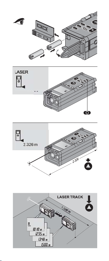
6. Before use
Symbol
displayed
6.1 Inserting new batteries
-NOTEAlways replace the complete set of batteries!
- Do not mix old and new batteries!
- Do not mix batteries from various
manufacturers or of different types.
- Use only approved, undamaged batteries.
Battery voltage too low - insert
new batteries:
2x type AA (LR6 / AM3 / Mignon)
x
+
-
I
2
1
3
Page 19

14
6. Before use
If using rechargeable batteries, the pair of
batteries must be
- of the same make and the same model,
- of the same age and in the same state of charge.
6.2 Menu selection and settings
Menu overview
rEF¡nor¡CONST¡Light
¡
dELAY¡bEEP¡UNIT
6.2.1 rEF / reference point menu
Press the button to display the menu.
Select the rEF menu by pressing the
buttons.
Select the desired reference point by pressing
the buttons.
front edge of range meter
tripod thread
rear edge (=standard)
Press the button to exit menu mode.
MENU
rEF
MENU
–
+
MENU
Page 20

15
6. Before use
6.2.2 nor / track menu
Press the button to display the menu.
Select the tracking menu by pressing the
buttons.
Use the buttons to select the
desired mode.
nor = Normal continuous measurement
nEAr = For determining the shortest distance,
e.g. at right angles to the target
surface, for example, when checking
that walls are parallel.
FAr = For determining the maximum
distance, e.g. measuring diagonals for
checking right angles in rooms.
6.2.3 CONST / constants menu
Press the button to display the menu.
Select the CONST menu by pressing the
buttons.
Use the buttons to enter the
constant, e.g. 0.234.
The constant value can be changed in larger
increments by holding down the button
and then pressing the buttons.
–
+
MENU
nor
MENU
CONST
MENU
–
+
MENU
–
+
x
Page 21

16
6. Before use
The value entered can be recalled and used for
subsequent calculations (e.g. adding a constant
to measured values, etc.).
6.2.4 Light / display illumination menu
Press the button to display the menu.
Select the “Light” menu by pressing the
buttons.
Select the desired illumination mode by
pressing the buttons:
OFF Illumination off. Saves battery power.
ON Illumination on constantly.
Auto Display is illuminated for 10 seconds
after pressing a button.
6.2.5 dELAY / self-timer menu
Press the button to display the menu.
Select the dELAY menu by pressing the
buttons.
Use the buttons to select the
desired delay time (0 / 2 / 5 / 10 / 20). After
pressing the “measure” button, the measurement
will be taken automatically when the set time has
elapsed (e.g. for taking measurements from
points where access is difficult).
MENU
Light
MENU
dELAY
MENU
–
+
MENU
–
+
Page 22

17
6. Before use
6.2.6 bEEP / beep sound menu
Press the button to display the menu.
Use the buttons to select the bEEP
menu.
Use the buttons to select the
desired bEEP mode:
ON A beep is emitted when:
a button is pressed, a measurement
is taken, an error occurs.
OFF No beep sound
Auto A beep is emitted when:
a measurement is taken,
an error occurs.
6.2.7 UNIT / measurement units menu
Press the button to display the menu.
Use the buttons to select the UNIT
menu.
Use the buttons to select the
desired measuring unit:
m Value displayed in metres
in Value displayed in feet, inches and
fractions in 1/32 increments
MENU
bEEP
MENU
UNIT
MENU
–
+
MENU
–
+
Page 23

18
7. Operation
7. Operation
7.1 Measuring distances
1. Press the button to switch on the range
meter. The following is displayed:
The laser beam is switched on.
After switching on, the reference point is
always set to the rear edge of the range
meter (symbol).
2. Position the rear edge of the range meter at
the desired starting point and aim it at the
target from which the measurement is to be
taken.
3. Press the “measure” button .
The measured value is then displayed.
LASER
-------
I
Page 24

19
7. Operation
7.2 Measuring using the spike
7.2.1 Measuring from the corner of a room
The spike should be folded out when
measuring the diagonals of a room or when
taking measurements from corners where
access is difficult.
1. Fold the spike out to the 90° position.
The measuring reference point is changed
automatically.
The extended reference point is taken into
account and the range meter automatically
corrects the measured distance by the
corresponding value.
2. Position the end of the spike at the desired
starting point and aim the range meter at the
target from which the measurement is to be
taken.
3. Press the “measure” button .
The measured value is then displayed.
Page 25

20
7. Operation
7.2.2 Measuring from an outside corner
1. Fold out the spike to the 180° position.
2. Check the measuring reference point.
3. Position the range meter at the desired
starting point, with the spike up against the
corner, and aim the range meter at the target
from which the measurement is to be taken.
4. Press the “measure” button .
The measured value is then displayed.
7.3 Measuring using the self-timer
The self-timer can be of great assistance when
measuring from points that are difficult to
reach or impossible to reach without some
form of aid. The self-timer can be started by
pressing the “measure” button and the range
meter then held in the difficult-to-reach
position. An audible signal then indicates when
the measurement has been taken successfully.
LASER
+
-
I
PD 22
MEN
x
=
Page 26

21
7. Operation
7.4 Measuring with the aid of a target object
A board, bricks or other suitable objects can be
used as the target when taking a measurement
from an outside edge (e.g. outside walls of
houses, perimeter fences, etc.).
The measuring procedure is a described
previously (see 7.1).
7.5 Taking measurements from various
surfaces
7.5.1 Plants and trees
It is not possible, as a rule, to take
measurements from plants and trees, even
over very short distances. Matt green surfaces
decrease the range of the range meter.
Page 27

22
7. Operation
The measuring procedure is as described
previously (see 7.1).
7.5.2 Rough surfaces
On rough surfaces (e.g. rough plaster), the
measurement obtained is a weighted average,
whereby the centre of the laser beam receives a
higher weighting than the surrounding area.
The measuring procedure is as described
previously (see 7.1).
Page 28

23
7. Operation
7.6 Continuous measurement
(tracking)
1. Press the button.
2. Press the “measure” button once .
The words «LASER TRACKING» are then
shown in the display:
3. Move the range meter to each new position
and read off each distance as it is measured.
4. Tracking mode can be cancelled by pressing
any button.
7.6.1 Continuous measurement
«Tracking nEAr»
When «Tracking nEAr» is activated, the
shortest measured distance is always displayed
(e.g. for determining whether objects lie
parallel).
LASER TRACK
I
Page 29

24
7. Operation
Applications:
– Determining the shortest distance between
two objects without having to fix the point.
– Determining a distance at right angles to a
surface.
1. Switch on the range meter and then press
the button.
2. Press the buttons to display the
tracking menu.
3. Select the nEAr function by pressing the
or buttons.
4. Aim the range meter at the target surface.
5. Press the “measure” button.
6. Move the range meter slowly. The value
displayed is updated continuously.
Move the range meter until the lowest value
is displayed (shortest distance).
+
–
MENU
Page 30

25
7. Operation
7. Press the “measure” button again
to stop measuring. The result is then
displayed.
7.6.2 Continuous measurement
«Tracking FAr»
When «Tracking FAr» is activated, the longest
measured distance is always displayed (e.g. for
measuring a diagonal).
Application
– Determining the longest distance between
two objects without having to fix the point
(e.g. diagonals of a room, for checking right
angles).
1. Switch on the range meter and then press
the button.
2. Press the buttons to display the
tracking menu.
1.970 m
MENU
Page 31

26
3. Select the FAr function by pressing the
or buttons.
4. Aim the range meter at the target.
5. Press the “measure” button.
6. Move the range meter slowly. The value
displayed is updated continuously. Move
the range meter until the highest value is
displayed (longest distance).
7. Press the “measure” button
again to stop measuring. The result is then
displayed.
7. Operation
3.746 m
+
–
Page 32

27
7. Operation
7.7 Using the calculation functions
7.7.1 Addition / subtraction (distances)
Individual distances can be added or
subtracted easily.
The following example shows how 2
individual distances can be added together.
When a tripod is used:
Set the measuring reference to the tripod axis.
Distances greater than 100 m can be measured
in this way.
1. Press the “measure” button. The laser
switches on.
2. Aim the range meter at the target.
3. Press the “measure” button.
The first distance is measured and displayed
(laser switches off).
4. Press the button for addition.
5. Pivot the range meter through 180° between
measurements 1 and 2.
6. Press the “measure” button. The laser
switches on.
+
1-155m
2.260m
1.105m
Page 33

28
7. Operation
7. Aim the range meter at the target.
8. Press the “measure” button.
The second distance is measured and
displayed (laser switches off).
9. Press the “equals” button.
10. Read the total distance from the display.
7.7.2 Multiplication (areas / volumes)
Example 1:
Calculating the floor area of a room
Measure the width of the room.
1. Press the “measure” button.
2. Aim the range meter at the target.
3. Press the “measure” button.
The width of the room is measured and displayed (laser switches off).
4. Press the button for multiplication.
=
3.5m
x
Page 34

29
Measure the length of the room.
5. Press the “measure” button.
6. Aim the range meter at the target.
7. Press the “measure” button.
The length of the room is measured and
displayed (laser switches off).
8. Press the “equals” button.
9. Read the total floor area from the display.
Example 2:
Calculating the volume of a room
After calculating the floor area of the room:
10. Press the button for multiplication.
7. Operation
3.500m
x
8.375m
=
x
Page 35

30
7. Operation
11. Press the “measure” button.
12. Aim the range meter at the target.
13. Press the “measure” button.
The height of the room is measured and
displayed (laser switches off).
14. Press the “equals” button.
15. Read the total volume from the display
(66.980m3)
Consecutive calculations
Consecutive calculations can
be made without pressing the “equals”
button.
e.g. distance x distance x distance = m
3
or (distance x distance) + (distance x distance)
= m
2
29.313m
2
x
2.285m
=
=
Page 36
31
7. Operation
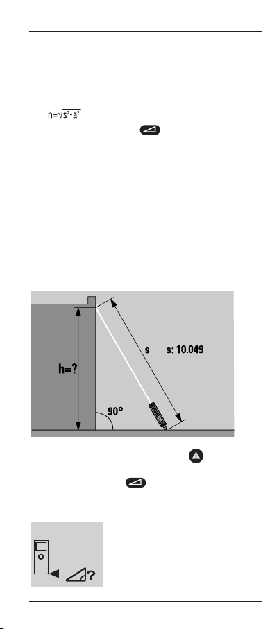
7.8 Calculations using the Pythagoras function
The Pythagoras function can be used, for
example, to quickly calculate heights etc.
The calculation formula is activated by
pressing the Pythagoras button.
-NOTE-
To ensure correct use of this function, the
adjacent side of the triangle measured must be
perpendicular to the opposite side that is to be
calculated (i.e. perpendicular to height h).
Failure to ensure that measurements are perpendicular will cause errors and the results
obtained may exceed the specified accuracy of
the range meter.
1. Measure the hypotenuse
Measure side “s” (the hypotenuse).
Press the Pythagoras button.
The following is displayed:
10.049m
Page 37

32
7. Operation
2. Measure the adjacent side
Measure side “a” (the adjacent side of the
triangle).
The following is displayed:
3. Calculate the opposite side
Calculate the height “h” (the opposite side
of the triangle) by pressing the “equals”
button.
The following is displayed:
10.049m
4.995m
8.720m
=
Page 38

33
7. Operation
7.9 Calculations using a constant value
Display the menu.
Select the CONst menu.
Enter the constant value.
-NOTE-
Pressing the “X” and “+” or “X” and “-” buttons
simultaneously increases or, respectively,
decreases the indicated value in increments of
0.100.
When calculating, press the buttons
to recall the previously entered constant value
(as the fourth or, respectively, the last step) and
then press the appropriate button to make the
desired calculation.
MENU
–
+
Page 39

34
8. Symbols displayed
8. Symbols displayed
Temperature too high
(> +50°C), in tracking mode
and in setting-out mode
(> +45°C)
Remedy
Allow the range meter to cool.
Temperature too low
(< -10°C)
Remedy
Warm the range meter.
Unfavourable laser signal
conditions
Remedy
– Observe the min. measuring
distance (> 100mm).
– Clean the lens.
– Take the measurement from a
different surface (target plate).
– Shade the target point from bright
light.
General hardware fault
Remedy
Switch the range meter off and on
again. Please contact the service
centre if the fault persists.
Batteries almost exhausted
Remedy
Insert new batteries.
Ambient light at target too bright
Remedy
Shade the target point from bright
light.
Page 40

35
9. Testing and adjustment
9. Testing and adjustment
The following paragraphs describe the
measuring equipment inspection procedures
applicable to range meter users certified in
accordance with ISO 900...
You may carry out the measuring equipment
inspection required by ISO 900... on the PD 22
linear measuring device yourself (see DIN
18723-6; Procedures for checking the accuracy
of geodetic instruments in the field: Part-6, optoelectronic range meters for short distances).
To do this, select a measuring distance which
remains constant over a period of time and which
is easily accessible. It should have a known length
of approx. 1 to 5 m (e.g. a window opening or the
width of a room). 10 measurements should be
made over the same distance.
Determine the mean deviation of the readings
from the nominal distance. This value should
be within the specified accuracy tolerance for
the range meter.
Keep a record of this value and the date for the
next inspection.
Repeat these test measurements at regular
intervals as well as before and after important
measuring tasks.
Apply a measuring equipment inspection
sticker to the PD 22 and keep a record of the
entire inspection procedure.
Please refer to the technical data contained in
the operating instructions and the information
concerning measuring accuracy.
Recommendation
Have the range meter checked once a year at a
Hilti workshop. Ask your Hilti representative for
further information or send the range meter
directly to one of our repair / service centres
with a note explaining that the range meter has
been sent for testing. Please also state whether
you require a certificate for your own records.
Page 41

36
10. Care and maintenance
10. Care and maintenance
10.1 Cleaning and drying
– Blow dust off the lenses.
– Do not touch the glass with your fingers.
– Use only clean, soft cloths for cleaning. If
necessary, moisten the cloths slightly with
pure alcohol or a little water.
-NOTE-
– Do not use any other liquids as these may
damage the plastic components.
– Observe the temperature limits when storing
your equipment. This is particularly
important in summer if the equipment is
kept inside a motor vehicle (storage temperatures: -30°C to +70°C / -22°F to +158°F)
– Replace damaged parts.
10.2 Storage
Remove the range meter from its case if it
has become wet. The range meter, its carrying
case and accessories should be cleaned and
dried (max. temperature: 40°C / 108°F)
Repack the equipment only when it is
completely dry.
Check the accuracy of the equipment
before it is used after a long period of storage
or transportation.
10.3 Transportation
Use the Hilti shipping carton or packaging of
equivalent quality for transporting or shipping
your equipment.
-NOTE-
Always remove the batteries before shipping.
Page 42

37
11. Disposal
Improper disposal of the equipment may have
serious consequences:
– The burning of plastic components
generates toxic fumes which may present a
health hazard.
– Batteries may explode if damaged or
exposed to very high temperatures, causing
poisoning, burns, acid burns or
environmental pollution.
– Careless disposal may permit unauthorised
persons to make improper use of the
equipment, possibly leading to serious
personal injury, injury to third parties and
pollution of the environment.
Most of the materials from which Hilti
machines or appliances are manufactured can
be recycled. The materials must be correctly
separated before they can be recycled.
In many countries, Hilti has already made
arrangements for taking back old machines and
appliances for recycling.
Ask Hilti customer service or your Hilti
representative for further information.
Should you wish to return the machine or
appliance yourself to a disposal facility for
recycling, proceed as follows: Dismantle it as far
as possible without the need for special tools.
Separate the individual parts as follows:
Part, assembly Main material Recycling
Casing, toolbox, target
plate, carrying case,
keypad Plastic Plastics recycling
Measuring module,
electronics Various Electronics scrap
Screws, small parts Steel Scrap metal
* Dispose of batteries in accordance with
national regulations.
Page 43

38
12. Warranty
12. Warranty
Hilti warrants that the product supplied is free of
defects in material and workmanship. This
warranty is valid so long as the product is
operated and handled correctly, cleaned and
serviced properly and in accordance with the
Hilti Operating Instructions, all warranty claims
are made within 12 months from the date of the
sale (invoice date), and the technical system is
maintained. This means that only original Hilti
consumables, components and spare parts may
be used in the product. (Unless stringent
national rules stipulate a longer minimum
warranty period.)
This warranty provides the free-of-charge repair
or replacement of defective parts only. Parts
requiring repair or replacement as a result of
normal wear and tear are not covered by this
warranty.
Additional claims are excluded, unless
stringent national rules prohibit such
exclusion. In particular, Hilti is not obligated
for direct, indirect, incidental or consequential
damages, losses or expenses in connection
with, or by reason of, the use of, or inability to
use the product for any purpose. Implied
warranties of merchantability or fitness for a
particular purpose are specifically excluded.
For repair or replacement, send product and / or
related parts immediately upon discovery of the
defect to the address of the local Hilti marketing
organization provided.
This constitutes Hilit’s entire obligation with
regard to warranty and supersedes all prior or
contemporaneous comments and oral or written
agreements concerning warranties.
Page 44

39
13. FCC statement (applicable in US)
13. FCC statement (applicable in US)
This equipment has been tested and found to
comply with the limits for a Class B digital
device, pursuant to part 15 of the FCC rules.
This device complies with part 15 of the FCC
rules. Operation is subject of the following
conditions:
(1) This device may not cause harmful
interference, and (2) this device must accept
any interference received, including
interference that may cause undesired
operation.
These limits are designed to provide reasonable
protection against harmful interference in a
residential installation. This equipment
generates, uses and can radiate radio
frequency energy and, if not installed and used
in accordance with the instructions, may cause
harmful interference to radio communications.
However, there is no guarantee that
interference will not occur in a particular
installation. If this equipment does cause
harmful interference to radio or television
reception, which can be determined by turning
the equipment off and on, the user is
encouraged to try to correct the interference by
one or more of the following measures:
– Reorient or relocate the receiving antenna.
– Increase the separation between the
equipment and receiver.
– Connect the equipment to an outlet on a
circuit different from that to which the
receiver is connected.
– Consult the dealer or an experienced
radio/TV technician for help.
Changes or modifications not expressly
approved by Hilti for compliance could void the
user’s authority to operate the equipment.
Page 45

40
Product information plate
Type: PD 22
319196
Made in Germany
Page 46

41
14. EC declaration of conformity
14. EC declaration of conformity
Designation: Laser range meter
Type: PD 22
Year of design: 2002
In conformance with
We declare, on our sole responsibility, that this
product complies with the following standards
or standardisation documents:
DIN EN 50081-1, DIN EN 61000-6-2, DIN EN
50082-1, DIN EN 50082-2, 89/336/EEC
Hilti Corporation
Armin Spiegel
Leiter BU Positioning
Systems
Head of Positioning
Systems Business Unit
01 / 2002
Bodo Baur
Leiter Qualität
Positioning Systems
Quality Manager,
Positioning Systems
Business Unit
01 / 2002
Positioning Systems 01/2002
 Loading...