

Page 1
DS HS64-12/14
*206873*
DS HS80-12/14/16
Operating instructions en
Mode d’emploi fr
Manual de instrucciones es
206873
Page 2
1
18
17
16
12
101112131415
3
4
5
6
7
8
9
DS HS80-40
27
26
25
24
19
31
29
30
28
20
21
22 / 23
Page 3
2
5
3
4
1/9 310 2
3
2
9
1
2
4
746
5/7
180˚
4
10
9/10 8
5
1
3
7
6
2
8
3/4
10
1
9
3/4
5
Page 4
6
9/10
2
1
4
5/11
7
8
8
76
3/13
9
1/13/14 6/12
3/4/5
2
7/11
8
9
10
10
1
2
3
1
4
6
8
5
13
11
7
5 - 7x
13
Page 5
11 12
1/11/12 2/10
13
14
3 2/4 1/5
1/3 2
1 6/11 5/12
4/10/14
3 9
0.5 mm
(
0.02"
)
5/6
4/8
3/9
9
15
13 2/15
8 7/8
T
Page 6
16
4
5
13/14 10
7
8/11
9
17
7
3
3/6
1
2 / 4
2
12
18
9
2
9
6
5
4
3
9 11
7 / 8 / 12
13
8
10
Page 7

DS HS64-12/14 and DS HS80-12/14/16 cut-off saws
DS HS64-12"
Max. 5100 rpm
Max.Blade Ø 12"
Arbor Ø 0.787"(20mm) or Ø 1"(25.4mm)
63.3cm
280360
01
05
0000000000
Made in Italy
Hilti = registered trademark of Hilti Corporation, Schaan, LI
DS FS-12/14
Made in Italy
Hilti= registered trademark of the Hilti Corporation, Schaan, Liechtenstein
Hand Held Gas Saw Model:
Hilti - DS KC62-12”/14”
Hilti - DS KC80-12”/14”
280025
01
03
1353490001
It is essential that the operating instructions are read before the
machine is operated for the first time.
Always keep these operating instructions together with the
machine.
Ensure that the operating instructions are with the machine when
it is given to other persons.
-Warning-
Some dust created by power sanding, sawing, grinding, drilling and other construction work contains chemicals known (to the State of California) to cause cancer, birth defects or other reproductive harm. Some examples of these chemicals
are:
● lead from lead-based paints
● crystalline silica from bricks and cement and other masonry products
Your risk from such exposure varies, depending on how often you do this type of
work. To reduce your exposure to these chemicals always work in a well ventilated
area and with approved safety equipment, such as dust masks specially designed
to filter out microscopic particles.
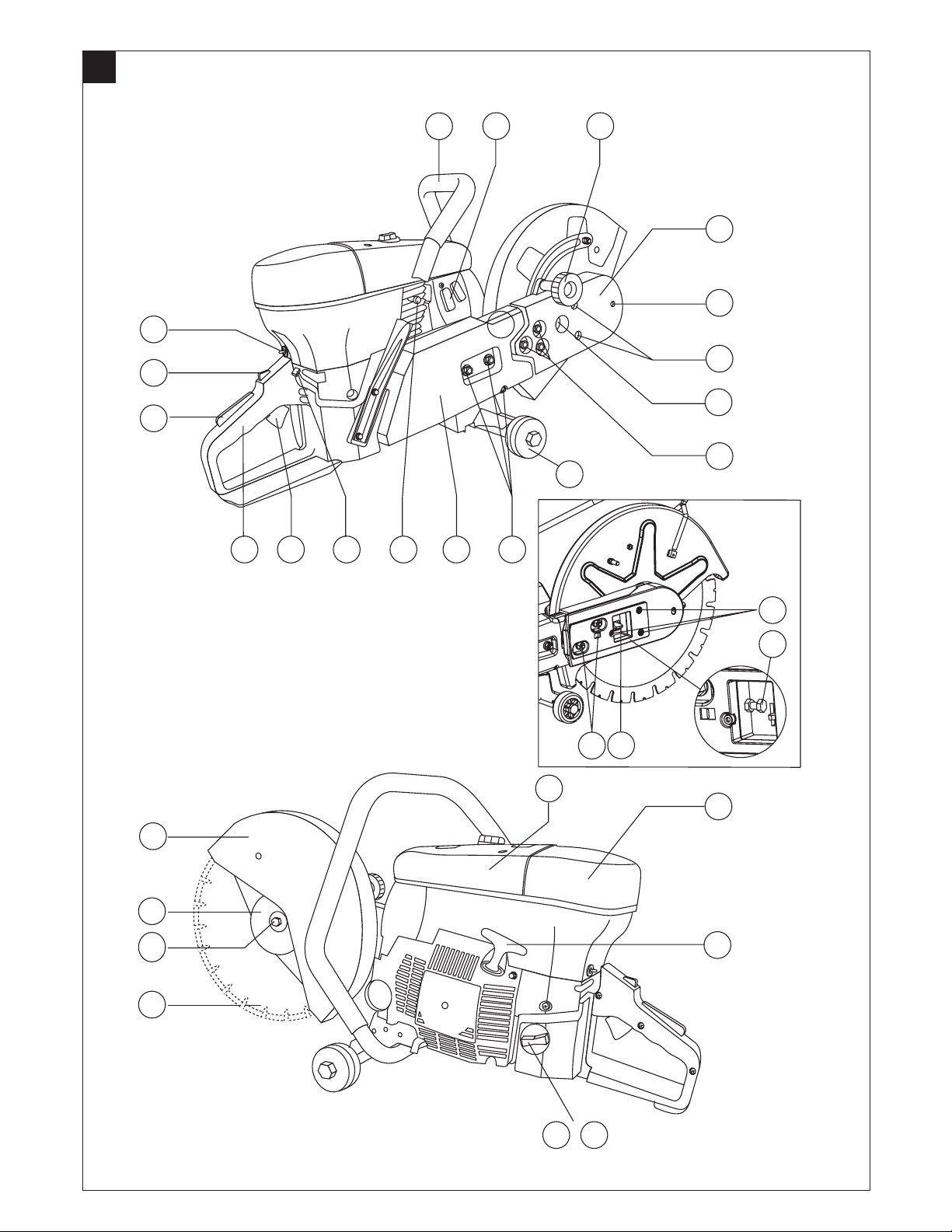
Operating controls, components and indicators
@ Front grip
; Exhaust / muffler
= Cutting disc guard clamping screw
% Front V-belt cover
& Cutting disc locking hole
( V-belt cover fastening screws
) V-belt tensioning cam
+ Securing nuts for saw arm front part (3 nuts)
§ Wheels or feet
/ Securing nuts for saw arm rear part (2 nuts) and hex. socket screw
: Saw arm
· Decompression valve
$ Choke lever
£ Throttle trigger
| Rear grip
¡ Throttle safety grip
Q Lock for half-throttle
W Start/stop switch
E Cover – air pre-filter
R Cover – main air filter and spark plug
T Starter handle
Z Fuel tank cap
U Fuel filter
I Abrasive or diamond disc
O Cutting disc securing screw
P Cutting disc mounting flange
Ü Cutting disc guard
DS HS80-16
[ Locking catch
] V-belt cover fastening screws
Æ Belt tensioning screw
º Securing nuts for saw arm front part (2 nuts)
Contents Page
1. General information 1
2. Description 2
3. Tools and accessories 2
4. Technical data 3
5. Safety precautions 4
6. Before use 5
7. Operation 6
8. Care and maintenance 7
9. Troubleshooting 9
10. Disposal 10
11. Federal emission control warranty statement 10
12. Warranty 11
1. General information
1.1 Safety notices and their meaning
-WARNING-
Draws attention to a potentially dangerous situation that could lead to serious personal injury or fatality.
-CAUTION-
Draws attention to a potentially dangerous situation that could lead to slight personal injury or damage to the equipment or other property.
-NOTE-
Draws attention to instructions and other useful information that help the user to
employ the product efficiently.
1.2 Pictograms
Prohibition signs
The use of damaged cutting discs is
Use of the tool without the disc guard is
prohibited
prohibited
Smoking
prohibited
Use of circular
saw blades is not
permissible
Warning signs
General
warning
Warning: hot
surface
Warning*) Warning**)
-Warning-*)
● Cutting (especially dry cutting) produces large amounts of dust which is injuri-
ous to health.
● The operator and any persons nearby must wear a suitable dust mask while the
machine is in use.
● Avoid inhaling gasoline vapors and exhaust gases.
-Warning-**)
● Exhaust fumes containing hot sparks and sparks produced when cutting can
cause fires and/or explosions.
● Make sure that any sparks produced cannot reach flammable (gasoline, dry grass,
etc.) or explosive substances (gas, etc.).
Obligation signs
Wear a hard
hat
Wear eye
protection
Wear a dust
mask
Wear ear
protectors
Wear
protective
gloves
Wear safety
footwear
Symbols
Read the operat-
STOP
These numbers refer to the corresponding illustrations. The illustrations can be
found on the fold-out cover pages. Keep these pages open while studying the operating instructions.
In these operating instructions, the DS HS64-12/14 or DS HS80-12/14/16 cut-off
saw is referred to as "the machine".
Location of identification data on the machine
The type designation and serial number can be found on the rating plate on the
machine. Make a note of this data in your operating instructions and always refer
to it when making an enquiry to your Hilti representative or service center.
Type: Type:
ing instructions
before use.
Type
Serial no.
Typ e
Serial no.
Serial no.: Serial no.:
en
1
Page 8

2. Description
2.1 Use of the machine as intended
The machine is intended for hand-held or walk-behind use (on an accessory trolley) for dry or wet cutting of asphalt and mineral or metallic construction materials
en
by means of abrasive or diamond cutting discs. The working environment corresponds to a typical construction site environment.
Manipulation or modification of the machine or accessories is not permissible. To
avoid risk of injury, use only original Hilti accessories and tools.
Do not use the machine to cut readily flammable materials or materials that present
a health hazard, e.g. asbestos, magnesium, timber, etc. To reduce the amount of
dust produced when cutting, we recommend use of the wet cutting method.
Observe the information printed in the operating instructions concerning operation,
care and maintenance. Observe the safety precautions and operating instructions
for the accessories used.
The machine, its accessories and discs may present hazards when used incorrectly by untrained personnel or not as directed.
3. Tools and accessories
3.1 Spare parts (wearing parts) for the DS HS cut-off saw
MODEL DS HS64-12 AND DS HS64-14
ITEM NUMBER SUGGESTED ORDER QTY DESCRIPTION
279853 2 ARBOR - SCREW M8
279856 1 ARBOR - FLANGE
279857 1 ARBOR - FLANGE 20 MM AND 1"
279878 2 ARBOR - BUSHING
279888 3 DRIVE BELT - TENSION HEXNUT
279884 4 DRIVE BELT - TENSION WASHER
279889 1 DRIVE BELT - COVER
279890 4 DRIVE BELT
279882 2 GUARD ADJ. - KNOB
279881 2 GUARD ADJ. - WASHER
279876 2 GUARD ADJ. - SPACER
279863 2 GUARD ADJ. - CLIP
279765 24 AIRFILTER - PRE-FILTER DS KC62
279776 6 AIRFILTER - MAINFILTER
279771 2 AIRFILTER – POLICE FILTER
279844 6 SPARK PLUG
279758 1 FILLER CAP - ASSEMBLY
279757 6 FILLER CAP - SEAL
342542 6 FUEL FILTER
279913 9 STARTER - FASTENING SCREW
279906 1 STARTER - ASSEMBLY
279897 12 STARTER - ROPE
279896 1 STARTER - HANDLE
279902 4 STARTER - SPRING ASSEMBLY
279745 2 LEVER - CHOKE
279793 2 LEVER - THROTTLE LOCK
279791 2 LEVER - THROTTLE TRIGGER
280026 3 TOOK KIT
279800 3 WEAR-PLATE
279799 6 SHOCK ABSORBER
279754 3 BREATHER ASSEMBLY
2.2 Items supplied
– Cut-off saw
– Tool kit comprising spark plug wrench, locking pin and Allen key
– Spare air pre-filter
– Water supply
– Feet
– Operating instructions
MODEL DS HS80-12, DS HS80-14 AND DS HS80-16
ITEM NUMBER SUGGESTED ORDER QTY DESCRIPTION
279853 2 ARBOR - SCREW M8
279856 1 ARBOR - FLANGE
279857 1 ARBOR - FLANGE 20 MM AND 1"
279878 2 ARBOR - BUSHING
279888 3 DRIVE BELT - TENSION HEXNUT
279887 3 DRIVE BELT - TENSION WASHER
279889 1 DRIVE BELT - COVER
280009 4 DRIVE BELT
279882 2 GUARD ADJ. - KNOB
279881 2 GUARD ADJ. - WASHER
279876 2 GUARD ADJ. - SPACER
279863 2 GUARD ADJ. - CLIP
279964 24 AIRFILTER - PRE-FILTER DS KC80
279776 6 AIRFILTER - MAINFILTER
279771 2 AIRFILTER - POLICFILTER
279844 6 SPARK PLUG
279758 1 FILLER CAP - ASSEMBLY
279757 6 FILLER CAP - SEAL
342542 6 FUEL FILTER
279898 4 STARTER - FASTENING SCREW
342543 1 STARTER - ASSEMBLY
279897 12 STARTER - ROPE
279896 1 STARTER - HANDLE
279902 4 STARTER - SPRING
279960 2 LEVER - CHOKE
279793 2 LEVER - THROTTLE LOCK
279791 2 LEVER - THROTTLE TRIGGER
280026 3 TOOK KIT
279973 3 WEAR-PLATE
279799 6 SHOCK ABSORBER
279754 3 BREATHER ASSEMBLY
3.2 Accessories for DS HS cut-off saw
ITEM NUMBER SUGGESTED ORDER QTY DESCRIPTION
280010 1 WATER SUPPLY KIT - PRO
9829 1 PRESSURE WATER TANK
279777 1 MAIN-AIRFILTER - WET APPLICAT.
282235 1 FLOOR SAW CART DS FC-12/14
342544 4 2-STROKE OIL DS KC (6 pcs/pack)
2
Page 9

3.3 Cutting discs
3.3.1 Abrasive cutting discs for hand-guided cut-off saws
Abrasive cutting discs for cut-off saws are composed of synthetic resin-bonded
abrasive granulate. To improve their fracture behavior and strength, these cutting
discs feature reinforcing fabric or fibers.
● Use only synthetic resin-bonded cutting discs approved for use with hand-held
cut-off saws and which satisfy the requirements according to EN 12413.
● Do not use cutting discs with a thickness of less than 1/8" (3 mm). Observe the
safety information and instructions for use given by the manufacturer of the cutting disc.
● Use only cutting discs approved for use at a speed of rotation higher than the
maximum speed of the cut-off saw under no load.
● Remove the cutting disc from the machine after use. Transporting the machine
with the cutting disc installed could damage the cutting disc.
● Store cutting discs according to the manufacturer’s recommendations. Improp-
er storage can result in damage to cutting discs.
● Never use damaged cutting discs or cutting discs of unknown origin.
● Abrasive cutting discs which have been used with cut-off saws for wet cutting
must be used completely the same day as the effects of long-term exposure to
water and moisture impair the strength of cutting discs.
● Take note of the shelf-life date on the cutting discs and do not use cutting discs
after expiry of this date.
Applications
-NOTE-
● Abrasive cutting discs for cut-off saws are used mainly for cutting ferrous and
non-ferrous metals.
● Various grit types such as aluminum oxide, silicon carbide, zirconium, etc., with
a different bonding material (matrix) or matrix hardness, are available depending on the construction material to be cut.
3.3.2 Diamond cutting discs for hand-held cut-off saws
Diamond cutting discs for cut-off saws consist of a steel core (disc) with diamond
segments (metallically bonded industrial diamonds).
● Use only diamond cutting discs approved for use with hand-held cut-off saws
and which satisfy the requirements according to EN 13236.
● Use only cutting discs designed for the maximum speed of the cut-off saw and
which comply with the cutting disc manufacturer's safety information and instructions for use.
● Ensure that the arrow marked on the cutting disc corresponds to the direction of
rotation of the machine.
● Remove the cutting disc from the machine after use. Transporting the machine
with the cutting disc installed could damage the cutting disc.
● Sharpen "polished” diamond cutting discs (no diamonds projecting from the
matrix) by cutting into highly abrasive materials such as sandstone.
● Never use damaged diamond cutting discs (cracks in the steel disc, broken-off
or distorted diamond segments, blunted segments, damaged mounting bore,
bent or distorted steel disc, severe discoloration through overheating, worn steel
disc under the diamond segments, diamond segments with no lateral projection,
etc.).
Applications
-NOTE-
● Segmented diamond cutting discs or those with a continuous cutting face are
mainly used for cutting asphalt and mineral construction materials.
Application recommendation
● We recommend that the workpiece is not cut through in a single operation. Advance
to the required depth of cut by making several to-and-fro movements.
● To avoid damaging the diamond cutting disc when dry cutting, lift the blade out
of the cut for approx. 10 seconds every 30 to 60 seconds while the machine is
still running.
● To reduce the amount of dust produced when cutting mineral materials and asphalt,
we recommend use of the wet cutting method.
en
4. Technical data
Machine DS HS64 DS HS64 DS HS80 DS HS80 DS HS80
Engine type two-stroke / single cylinder / air-cooled
Cubic capacity 3.9 cu (63.3 cm3) 5.0 cu (80.7 cm3)
Bore and stroke 48 mm / 35 mm 52 mm / 38 mm
Weight without disc 22.5 lb (10.2 kg) 22.9 lb (10.4 kg) 24.6 lb (11.2 kg) 25.1 lb (11.4 kg) 29.9 lb (13.6 kg)
Power 3.0 kW 3.7 kW
Maximum arbor speed 5100 r.p.m. 4700 r.p.m.
Engine speed 10000 ± 200 r.p.m.
No-load speed 2500–3000 r.p.m.
Dimensions
- Length 29.1" (740 mm) 31.5" (800 mm) 34.3" (870 mm)
- Width 15.8" (400 mm) 15.8" (400 mm) 17.3" (440 mm)
- Height 8.3" (210 mm) 8.7" (220 mm) 8.7" (220 mm)
Ignition (type) Electronic speed control
Electrode gap 0.35 mm
Spark plug
- Manufacturer Champion / NKG
- Type RCJ4 / BPMR8Y
Carburetor
- Manufacturer Walbro Walbro
- Model HDA 207 WJ85
- Type diaphragm / jet diaphragm / jet
Fuel mixture 2% (50:1)
Tank volume (capacity) 0.18 gallon (700 cm3) 0.23 gallon (880 cm3)
Cutting disc mount reversible
Arbor diameter 20 mm und 1" (25.4 mm)
Cutting disc diameter 300 mm (12") 350 mm (14") 300 mm (12") 350 mm (14") 400 mm (16")
Maximum depth of cut 100 mm (4") 125 mm (5") 100 mm (4") 125 mm (5") 150 mm (6")
Noise level (pressure) LpA eq EN 1454 – EN ISO 11201 101 dB (A)* 102 dB (A)*
Noise level (power) L
wA eq EN 1454 – EN ISO 3744 109 dB (A)* 111 dB (A)*
Wear ear protectors!
Typical weighted vibration EN 1454 – EN 28662-1 9.5(SX)-11.4(DX) m/s
1
/2idling,1/2maximum speed), wear ear protectors!
* Average (
30 cm / 12" 35 cm / 14" 30 cm / 12" 35 cm / 14" 40 cm / 16"
2
(idling) (idling) m/s
9.2(SX)-10.9(DX) m/s
2
10.1(SX)-12.0(DX) m/s
11.0(SX)-11.7(DX) m/s
2
2
8.9(SX)-4.9(DX)
2
(idling)
10.9(SX)-11.5(DX)
(maximum speed) (maximum speed) (maximum speed)
3
Page 10

5. Safety precautions
5.1 Basic safety precautions
In addition to the technical safety information in the individual sections of these
operating instructions, the following rules must be strictly observed at all times.
en
5.2 Safety precautions at the workplace
● Make sure the working area is well illuminated.
● Ensure that the workplace is properly ventilated.
● Do not work in closed rooms. The CO in the exhaust gas can cause suffocation.
● Keep the workplace tidy. Objects which could cause injury should be removed
from the working area. Untidiness at the workplace can lead to accidents.
● Make sure that work pieces are securely held when cutting. Never hold the work
piece in your hand. Where required, use clamps or a vice to hold the workpiece
firmly.
● The operator and any persons nearby must wear eye protection while the machine
is in use.
● The operator and any persons nearby must wear a suitable dust mask while the
machine is in use for dusty work.
● Wear suitable working clothing. Do not wear loose clothing, loose long hair or
jewelry as it can become caught up in moving parts. Wear suitable headgear if
you have long hair.
● When working, you are recommended to wear protective gloves and non-slip
footwear.
● Keep children away. Keep all other persons away from the working area.
● Avoid adopting an abnormal body stance. Be sure to stand steadily and keep your
balance at all times.
● Buried or covered electrical cables, gas and water pipes represent a serious haz-
ard if damaged whilst working. Before commencing work, check with the responsible site management that the working area is free of cables and pipelines and
that stress analysis or design of the structure is not impaired by the cutting work.
Outer metal parts of the machine can become live if you inadvertently damage an
electric cable.
● Do not work from a ladder.
● Never work above shoulder height.
● When using the wet cutting method, ensure that the water is drained off in a con-
trolled fashion and that the area around where you are working is not damaged
by running or spraying water.
● Safety measures must also be applied to the area beneath where you are work-
ing (cordon off the area).
5.3 General safety precautions
● Use the right machine for the job. Do not use the machine for purposes for which
it was not intended. Use the machine only as directed and when it is in faultless
condition.
● Avoid contact with rotating parts.
● Use only original accessories or additional equipment as listed in the operating
instructions. The use of accessories or additional equipment other than those
recommended in the operating instructions can present a risk of injury for you.
● Comply with the manufacturer's instructions when using abrasive and diamond
cutting discs.
● Make certain that the dimensions and specifications of the cutting disc conform
with the machine.
● Cutting discs must be stored and handled with care according to the manufac-
turer's instructions.
● Make certain that the cutting discs are mounted according to the manufacturer's
instructions.
● Make allowance for environmental influences. Do not use the machine where
there is a risk of fire or explosion.
● Keep the grips clean, dry and free from oil and grease.
● Do not overload your machine. You will work better and more safely if you keep
within the stated performance range.
● Use only the cutting discs which are recommended for this machine.
● Use only cutting or grinding discs approved for use at a speed at least as high as
the highest no-load speed of the tool.
● Damaged discs, or discs that are out of round or cause vibration, must not be
used.
● Use the machine only when the disc guard is correctly fitted and in good condition.
● Do not, under any circumstances, use the machine without the disc guard.
● Adjust the disc guard correctly to protect yourself against fragments or sparks
that may fly off.
● Always hold the machine firmly with both hands and by the grips provided.
● Store machines which are not in use in a safe place. Machines not in use should
be kept in a dry, high-up or locked place, out of the reach of children.
● Switch the machine off before transporting it.
● Switch the machine off before changing cutting discs.
● Switch the machine off before changing the cutting disc or adjusting the cutting
disc guard.
4
● Switch the machine off after use.
● Do not leave the machine unattended while it is running.
● Make sure the machine stands securely when it is laid down.
● Adjust the cutting disc guard correctly.
● Mount either the feet or wheels, depending on the application.
● Check whether moving parts function correctly and do not jam or whether parts
are damaged. All parts must be properly mounted and satisfy all conditions to
guarantee effective operation of the machine.
● Always cut at the full throttle setting.
● Guide the machine uniformly and without exerting lateral pressure on the cutting
disc.
● When cutting, exert only enough pressure for the speed to remain constant and
for the speed not to drop too sharply.
● Never use the machine / cutting disc for grinding and do not apply lateral pres-
sure to the cutting disc.
● Check the machine, cutting disc and accessories for correct condition and func-
tioning. Do not operate the machine if it is damaged, malfunctioning, incomplete,
parts are not mounted correctly or if the operating and adjusting components
cannot be properly used. .
● Functional faults and / or damage are only to be rectified by qualified repair per-
sonnel using original spare or wearing parts.
● Do not use saw blades with cutting teeth.
● Do not attempt to brake or stop rotation of the cutting disc with the hand.
5.3.1 Mechanical hazards
● Follow the instructions for care and maintenance.
● Make sure that cutting discs have mounting bores and blade thicknesses suit-
able for the machine and are clamped correctly between the mounting flanges.
● When mounting the cutting disc, always make sure that the direction of rotation
marked on the cutting disc corresponds to the direction of rotation of the machine.
● Use only disc mounting / clamping flanges designed for use with this machine.
5.3.2 Thermal hazards
Warning: Wear
hot protective
surface gloves
The cutting disc can become hot through use. Always wear protective gloves
●
when changing the blade.
● Exhaust and engine become very hot. Hold the machine only by the grips provided.
5.3.3 Fluids (gasoline and oil)
● Store gasoline and oil in a well ventilated room in fuel containers that comply with
regulations.
● Allow the machine to cool before refueling. Do not refuel the machine whilst it is
hot.
● When refueling, use a suitable funnel.
● Do not use gasoline or other flammable liquids for cleaning work.
● Do not refuel the machine in the vicinity of the working area.
● Take care to avoid spilling gasoline while refueling.
5.3.4 Slurry from wet cutting
● Avoid skin contact with cutting slurry.
5.3.5 Vapors
● Do not smoke whilst refueling.
● Avoid inhaling gasoline vapors and exhaust fumes.
5.3.6 Dust
Wear a
dust
mask
The operator and any persons nearby must wear a suitable dust mask while the
●
machine is in use for dusty work.
● Dust and gas with chemical constituents may be produced when cutting unknown
materials. Such substances can seriously damage your health. Obtain information from the client or the responsible authorities concerning the hazard level of
such materials. The operator and any persons in the vicinity must wear dust masks
approved for the substance in question.
● To reduce the amount of dust produced when cutting mineral materials and asphalt,
we recommend use of the wet cutting method.
Page 11

5.4 Requirements to be met by users
● The machine is intended for professional use.
● The machine may be operated, serviced and repaired only by authorized, trained
personnel. This personnel must be informed of any special hazards that may be
encountered.
● Always concentrate on the job you are doing. Proceed carefully and do not use
the machine if your full attention is not on the job.
● Exercise your fingers during pauses between work to improve the circulation of
blood in your fingers. Wear protective gloves. Comply with your national work
and health safety regulations and laws.
● Do not use the machine while under the influence of drugs / medication or alcohol.
6. Before use
6.1 Mixing and storing fuel
-CAUTION-
The two-stroke engine runs on a mixture of gasoline and oil. The quality of the fuel
mixture decisively influences the function and life expectancy of the engine.
● Avoid direct skin contact with gasoline.
● To avoid inhaling gasoline vapors, ensure that the work place is well ventilated.
● Use a fuel container that complies with the applicable regulations.
6.1.1 Engine oil
Use Hilti two-stroke engine oil for air-cooled engines or a quality two-stroke engine
oil with the TC classification.
6.1.2 Gasoline
● Use unleaded normal or super gasoline with an octane rating of at least 92 ROZ.
● The alcohol content of the utilized fuels should not exceed 10 %. Failure to observe
this point may considerably reduce engine life expectancy.
6.1.3 Mixing the fuel
-CAUTION-
The motor will suffer damage if the fuel used is mixed to the incorrect ratio or with
unsuitable oil.
Mixing ratio with Hilti two-stroke engine oil = 1 part oil + 50 parts gasoline.
Mixing ratio with quality two-stroke engine oil with the TC classification = 1 part oil
+ 25 parts gasoline.
1. First place the oil in the fuel container.
2. Next add the gasoline to the fuel container.
3. Close the fuel container.
4. Mix the fuel by shaking the fuel container.
6.1.4 Storing the fuel mixture
● Mix only enough fuel for a few day’s use.
● As pressure can build up inside the fuel container, open the cap carefully.
● Store the fuel in a dry, well ventilated room.
● Clean the fuel container occasionally.
6.2 Filling with fuel / refueling the saw
-WARNING-
● Do not refuel the machine in the vicinity of the working area (at least 10 feet
(3 m) away from the workplace).
● Do not smoke whilst refueling.
● Do not refuel the machine in a room where an open flame or sparks can ignite
the gasoline vapors.
● Do not refuel the machine with the engine running.
● Do not refuel the machine when the engine is hot.
● Wear suitable protective gloves when refueling.
● Do not spill any fuel.
● It is imperative to change your clothing if this is soiled with fuel whilst refueling.
1. Mix the fuel (engine oil / gasoline mixture) by shaking the fuel container.
2. Place the machine in a steady position on its side. (Filler cap facing up.)
3. Open the filler cap by turning it counterclockwise.
4. Replenish with fuel slowly using a funnel.
5. Close the filler cap on the machine by turning it clockwise.
6. Close the fuel container.
-WARNING-
● After refueling, clean off any spilt fuel from the machine and accessories.
● Check the machine for leaks. Do not start the engine if any fuel spills out.
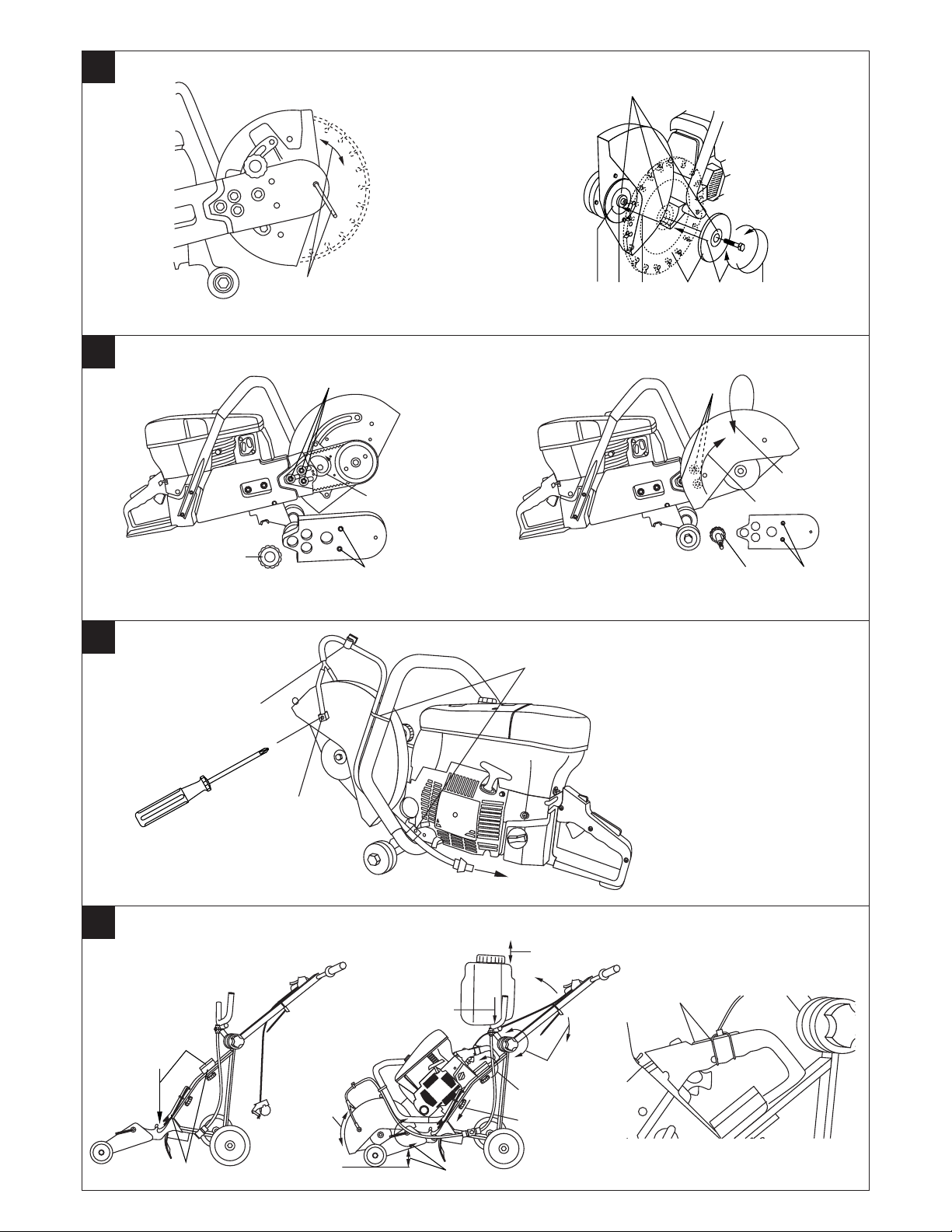
6.3 Mounting and changing the cutting disc
-WARNING-
● Do not use faulty cutting discs.
5.5 Personal protective equipment
● Whilst the machine is in operation, the user and persons in the close vicinity must
wear suitable hard hats, eye protection, breathing protections, ear protectors,
protective gloves and safety footwear.
Wear eye
protection, ear
protectors and a
hard hat
● Do not mount cutting discs which are not approved for the prescribed speed.
● Use only cutting discs with 20 mm or 1" (25.4 mm) diameter mounting bores.
● Check the mounting flange, centering flange and drive arbor to ensure perfectly
Wear a dust
mask
Wear
protective
gloves
Wear safety
footwear
true running without wobble and check that the correct mounting / clamping
flange is used.
● Do not use abrasive cutting discs that have exceeded their use-by date.
● Check the cutting discs at regular intervals for signs of unusual wear or damage.
1. Insert the locking pin in the hole in the V-belt cover and turn the cutting disc
until the locking pin engages.
2. Turn the cutting disc securing screw counterclockwise.
3. Remove the cutting disc mounting flange and the cutting disc.
4. Check that the mounting bore of the cutting disc to be fitted corresponds with
the centering shoulder of the cutting disc mounting flange. The mounting flange
is provided with a 20 mm diameter centering shoulder on one side and a 1"
(25.4 mm) diameter centering shoulder on the opposite side.
5. Clean the clamping and centering surfaces on the mounting and fixing flange,
also on the cutting disc.
6. Place the mounting flange appropriately aligned on the drive arbor.
7. Place the cutting disc on the centering shoulder of the mounting flange. (Make
certain that the direction of rotation marked on the cutting disc corresponds to
that of the machine).
8. Place the securing flange on the drive arbor and tighten the cutting disc clamping screw by turning clockwise.
9. Insert the locking pin in the hole in the V-belt cover and turn the cutting disc
until the locking pin engages.
10. Tighten the cutting disc clamping screw to a torque of 18 ft-lbs (25 Nm).
6.4 Adjusting the cutting disc guard
-WARNING-
● Adjust the cutting disc guard correctly (it should direct expelled abraded parti-
cles away from the user and the machine.)
● Do not, under any circumstances, use the machine without the cutting disc guard
fitted.
1. Slacken the cutting disc guard clamping screw.
2. Rotate the cover to the desired position.
3. Tighten the clamping screw.
4. Make certain that the cover is securely fastened.
6.4 Adjusting the DS HS80-16 cutting disc guard
-WARNING-
● Adjust the cutting disc guard correctly (it should direct expelled abraded parti-
cles away from the user and the machine.)
● Do not, under any circumstances, use the machine without the cutting disc guard
fitted.
1. Press the locking lever and pivot the cutting disc guard into the desired position.
6.5 Rotating the front part of the saw arm – normal cutting / flush cutting
- NOTE-
● Where it is necessary to make cuts as close as possible (distance of approx.
30 mm) to walls, the front part of the saw arm can be rotated through 180° to
bring the cutting disc into a position suitable for this type of cut.
● After conversion, check that the cutting disc can be rotated easily by hand. If it
cannot be rotated easily, this indicates that the V-belt has not been correctly fitted.
- CAUTION-
● Adjust the cutting disc guard correctly (it should direct expelled abraded parti-
cles away from the user and the machine).
● Do not, under any circumstances, use the machine without the cutting disc guard
fitted.
● After completing the flush cut, reassemble the parts of the saw in their original
positions as the weight distribution of the machine is not optimal in the flush cutting position.
1. Slacken the two securing screws and remove the outer V-belt cover.
2. Turn the tensioning cam counterclockwise. (Straight side of cam is vertical.)
en
5
Page 12

3. Remove the three securing nuts and spacers, take off the belt and remove the
front part of the saw arm.
4. Turn the front part of the saw arm through 180°, place the V-belt on the front
belt pulley and insert the three fixing pins at the front part of the saw arm into
the slots at the rear part of the saw arm.
5. Fit the spacers and securing nuts (do not tighten).
en
6. Tension the belt by turning the tensioning cam clockwise (tension is correct
when the belt can be pressed down approx. 1 cm by hand).
7. Tighten the three hexagonal nuts.
8. Fit the front belt cover and secure it with the cheese-head screws.
9. Remove the clamping screw for the cutting disc guard.
10. Turn the cutting disc guard forward and tighten the clamping screw in the opposite fixing position.
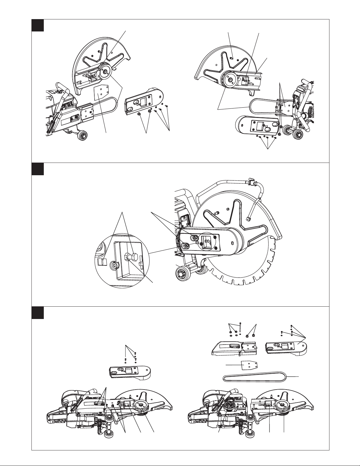
6.5 Reversing the front section of the DS HS80-16 saw arm – conversion from
normal-cutting to flush-cutting position
-NOTE-
● When it is necessary to make a cut as close as possible to a wall (distance approx.
30 mm), the front section of the saw arm can be fitted in the reversed position
(turned through 180°).
● After carrying out this operation, check that the cutting disc can be turned easi-
ly by hand and that all screws have been tightened securely.
- CAUTION-
● Adjust the cutting disc guard correctly (it should direct expelled abraded parti-
cles away from the user and the machine).
● Do not, under any circumstances, use the machine without the cutting disc guard
fitted.
● After completing the flush cut, reassemble the parts of the saw in their original
positions as the weight distribution of the machine is not optimal in the flush cutting position.
1. Place the machine on a level surface.
2. Release the three hex. socket screws (4 mm) and washers and remove the plas-
tic drive belt cover.
3. Slacken the two hex. nuts (13 mm AF) on the front section of the saw arm (do
not remove the nuts).
4. Release the lock nut (10 mm AF) on the belt tensioner and turn the tensioning
screw until the belt is completely slack.
5. Remove the belt from the front pulley (insert a small screwdriver between the
belt and the pulley and then rotate the pulley forwards by hand).
6. Remove the two hex. nuts (13 mm AF) and remove the front section of the saw
arm.
7. Remove the sheet metal spacer and then refit the front section of the saw arm
to the rear section in the reversed position (turned through 180°).
8. Fit the sheet metal spacer and the two hex. nuts (tighten the hex. nuts by hand,
only finger tight).
9. Fit the drive belt onto the front pulley (position the belt in the groove and then
rotate the pulley forwards by hand).
10. Turn the belt tensioning screw until the end of the pressure pin is positioned
approximately in the center of the indicator opening. Secure the tensioning screw
by tightening the lock nut.
11. Tighten the two hex. nuts (13 mm AF) on the front section of the saw arm securely.
12. Fit the front plastic drive belt cover and the three hex. socket screws (4 mm)
with washers.
13. Remove the stop pin (10 mm AF) from the blade guard and pivot the blade guard
until the previously used threaded hole is positioned above the saw arm.
14. Fit the stop pin in the upper of the two threaded holes.
15. Check again to ensure that all screws have been tightened securely and that the
belt is tensioned correctly.
6.6 Replacing the wheels with the feet
For working on roofs and / or slight gradients, the wheels can be replaced with feet.
The machine then stands more securely.
-CAUTION-
● Always use the fixed feet on roofs or surfaces with a slight gradient to prevent
the saw moving or falling inadvertently.
1. Slacken the wheel securing screws and remove the wheels.
2. Fit the feet and secure them with the retaining screws.
3. Make sure that the feet are secure.
6.7 Attaching the water supply
- NOTE -
● Wet cutting extends engine life expectancy and the air filter will also require less
frequent replacement.
● Water can be supplied through a hose, a pressure container (accessory) or the
water tank of the walk-behind trolley (accessory).
● For extensive wet cutting applications, we recommend the use of the heavy-duty
water supply unit (accessory) plus the main air filter of the type less sensitive to
water (accessory).
- CAUTION-
● To reduce the amount of dust produced, we recommend use of the wet cutting
method when cutting mineral materials and asphalt.
● To avoid damage to the cutting disc, ensure a uniform supply of water to the cut-
ting disc (on both sides).
1. Insert the water nozzles into the openings on the cutting disc guard.
2. Secure the hose with cable straps, as shown in the illustration.
3. Connect the water supply unit to the water supply hose or the water tank.
4. Regulate the water flow by means of the regulating valve when cutting.
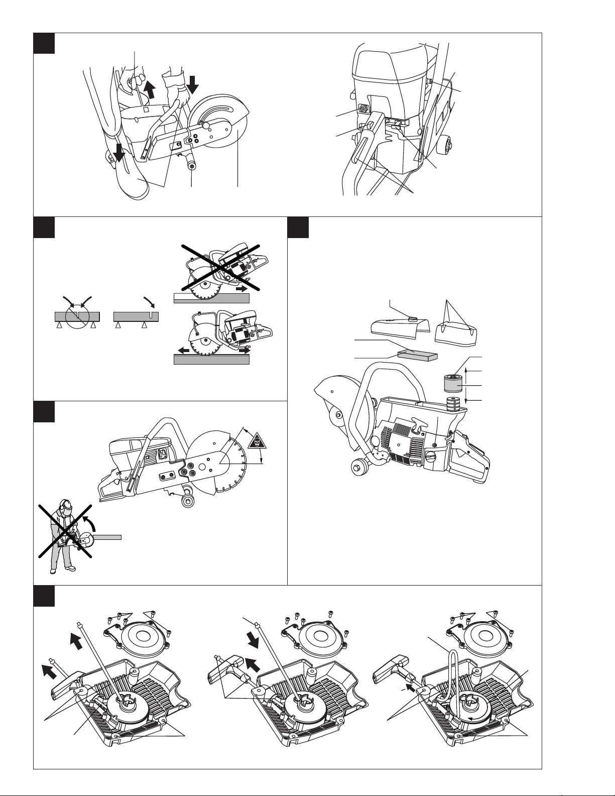
6.8 Guide trolley (accessory)
- NOTE -
● For extensive ground / floor cutting applications we recommend use of the walk-
behind guide trolley.
● Before mounting the cut-off saw on the trolley, make sure that the cutting disc
has been fitted and the saw refueled.
● Especially before operating the saw for the first time, make sure that the throttle
cable is correctly adjusted. When the throttle lever is pressed fully, the cut-off saw
must run at full throttle. If necessary, the throttle cable can be readjusted by turning the cable tensioner.
1. Release the upper and lower machine mounts on the guide trolley.
2. Introduce the arbor of the cut-off saw into the mounting fork on the guide trolley and place the rear grip of the cut-off saw on the shock absorber.
3. Push the lower machine mount forward and close the top machine mount.
4. Clamp the machine by tightening the upper and lower machine mounts.
5. Place the throttle cable of the guide trolley around the throttle trigger of the cutoff saw, as pictured and secure it with the clamping rubber.
6. Place the filled water tank in the holder and take care to ensure that the water
coupling engages properly in the opposing part.
7. The water flow can be switched on or off by pulling out or pressing in the knob
on the water tank. The required water flow rate can be adjusted with the aid of
the water control valve on the cut-off saw.
8. Bring the grip to a comfortable personal working height.
9. Set the depth of cut stop to the desired position by slackening the lever.
10. Adjust the cutting disc guard. (Make sure the guard will not touch the floor on
reaching the full depth of cut.)
7. Operation
7.1 Starting the engine
-WARNING-
● Keep other persons at least 50 ft (15 m) away from your workplace. Pay special
attention to the working area to your rear.
● Do not work in closed rooms. The CO in the exhaust can cause suffocation.
-CAUTION-
● The cutting disc must come to a complete stop when the motor is idling. The
idling speed must be readjusted (reduced) if necessary. If this is not possible or
does not bring the desired result, the saw must be sent in for repair.
● Check that the On /Off switch functions properly.
● If the throttle trigger jams, switch the machine off immediately by way of the On
/Off switch.
● After fitting a new cutting disc, the machine must be allowed to run without load
at full speed for approx. 1 min.
6
1. Move the On /Off switch to the "On" position.
2. Press the decompression valve.
3. Press the throttle safety grip, keep it pressed and then press the throttle trigger.
Hold these two controls in this position.
4. Use the half-throttle lock to lock the throttle trigger in the half-throttle position
and then release the safety throttle grip and the throttle trigger.
5. Pull out the choke lever.
6. Place the machine in a steady position on the ground.
7. Check that the cutting disc runs freely.
8. Hold the front grip firmly with the left hand and place the right foot in the lower
part of the rear grip.
9. With the right hand, slowly pull the starter handle until resistance is felt.
10. Pull the starter handle vigorously.
11. Push the choke lever back to the initial position after 2–3 start attempts.
12. Repeat this procedure, with the choke lever pushed in, until the engine starts.
13. As soon as the engine starts, briefly press the throttle trigger. This will release
the half-throttle lock and the engine will then run in the idling position. With the
throttle in the idling position, the cutting disc must not rotate.
Page 13

-CAUTION-
● The cutting disc and parts of the saw (exhaust, engine) become
hot when running.
● They can burn your hands.
● Wear protective gloves. Touch the machine only at the grips pro-
vided. Take great care to ensure that the hot machine does not
come into contact with flammable materials during transport and
in storage.
-WARNING-
● Material can shatter or splinter while being cut.
● Material splinters can injure the body and eyes.
● Wear eye protection, protective gloves and a dust mask when
working with dust-producing materials.
-WARNING-
● The machine and the cutting process produce noise.
● Excessive noise can permanently damage your hearing.
● Wear ear protectors.
7.2 Cutting technique
-WARNING-
● Always hold the machine securely with both hands, using the grips provided.
● Determine the cutting direction.
● Make certain no persons are present in the working area and especially not in the
area behind where the cut is to be made.
● Always bring the cutting disc into contact with the workpiece at right angles.
● Always cut at the full throttle position.
● For a clean cut, the disc should be "pulled” against the workpiece if possible or
moved to and fro along the line of the cut (do not push it against the workpiece).
● Take care to ensure that no persons are present in the working area in line with
the cutting disc in front of or behind the machine.
● Whilst cutting, do not change the cutting direction by exerting lateral pressure or
bending the cutting disc (risk of fracture or damage to the cutting disc).
● Secure the workpiece and the subsequent off-cut so that it cannot move in an
uncontrolled fashion.
7.2.1 Avoid jamming
● Avoid jamming the cutting disc in the workpiece. A jammed cutting disc can cause
a violent twisting movement of the machine.
● Support the workpiece in such a way that the cut remains open during and after
cutting.
7.2.2 Avoid kick-back
● Always bring the machine into contact with the workpiece from above. The cut-
ting disc must only contact the workpiece at a point below the center of rotation.
● Take special care when bringing the cutting disc into an existing cut.
7.3 Switching off the engine
1. Release the throttle lever.
2. Move the On/Off switch to the "Off" position.
en
8. Care and maintenance
-WARNING-
Switch off the machine before all servicing, repairs, cleaning and maintenance.
8.1 Maintenance schedule
Visual inspection of complete machine X X X
Before starting work
Functional check: Safety throttle grip, throttle trigger and half-throttle lock X X X X X
Functional check of the choke lever X X X X
Functional check of the On/Off switch X X X X X
Functional check of the decompression valve X
Visual inspection: Starter rope wear X X
Leak test of fuel tank and filler cap X X X X
Visual and functional check of the cutting disc guard X
Visual inspection: Cleanliness of fuel filter X X
Visual and functional check: V-belt tension and condition X X X X X
Visual inspection: Cleanliness of air pre-filter X X X X
Visual inspection: Cleanliness of the main air filter X X X
Visual inspection of the cleanliness of the breather openings on the starter and
filter housings X X X
Visual inspection of the cleanliness of the cylinder cooling fins X X
Visual inspection for pitting, electrode gap and spark plug function X X X every100hrs.
Visual and functional check: No rotation of the cutting disc during idling X X X X X
Functional check of the absorber elements X every100hrs.
Visual and functional check: Tightness of all visible securing screws X
Functional check: Starter return spring X X X
Visual inspection: Exhaust and muffler X X X X
Visual and functional check: Centrifugal clutch and belt pulley XXXX
Visual inspection: Cleanliness of fuel tank X X X
After completing work or
daily
Weekly
Monthly
Cleaning in case of exces-
sive dirt or malfunction
Adjustment or repair in
case of malfunction or
damage
Replacement if cleaning or
repair is impossibler
7
Page 14

8.2 Maintenance and repairs
8.2.1 Cleaning or replacing the air pre-filter
For optimal machine operation, the filters must not be blocked. Blocked or badly
maintained filters reduce engine power, increase fuel consumption, impair starting
behavior and increase engine wear.
en
-NOTE-
● Check the filter every 8 running hours. In the event of very harsh operating con-
ditions the main filter must also be replaced with each third replacement of the
pre-filter.
● Do not clean the filters with compressed air as this can create holes through which
unfiltered air can be drawn into the carburetor and the cylinder.
● Work whenever possible using the wet cutting method in order to reduce dust
loads for the operator and machine.
1. Open and remove the cover, including the pre-filter, by unscrewing the knob.
2. Remove the pre-filter from the cover.
3. Clean the pre-filter with warm soapy water.
4. Dry the pre-filter.
5. Rub some two-stroke oil (12g) onto the surface of the pre-filter by hand.
8.2.2 Cleaning or replacing the main air filter
-NOTE-
The pre-filter cover (see item 8.2.1) must be removed before the main filter can be
removed.
6. Remove the securing screws from the main filter cover.
7. Remove the main filter securing screw and take off the cover
8. Pull out the main filter in an upwards direction (ensure that the filter remains in
place so that no dirt can enter the carburetor or the engine).
9. Clean the main air filter with a soft brush.
10. Insert the main filter from above.
11. Replace the filter cover and tighten the main air filter.
12. Replace the main filter cover and tighten the securing screws.
13. Replace the cover with the air pre-filter.
14. Secure the cover, including the pre-filter, by tightening the knob.
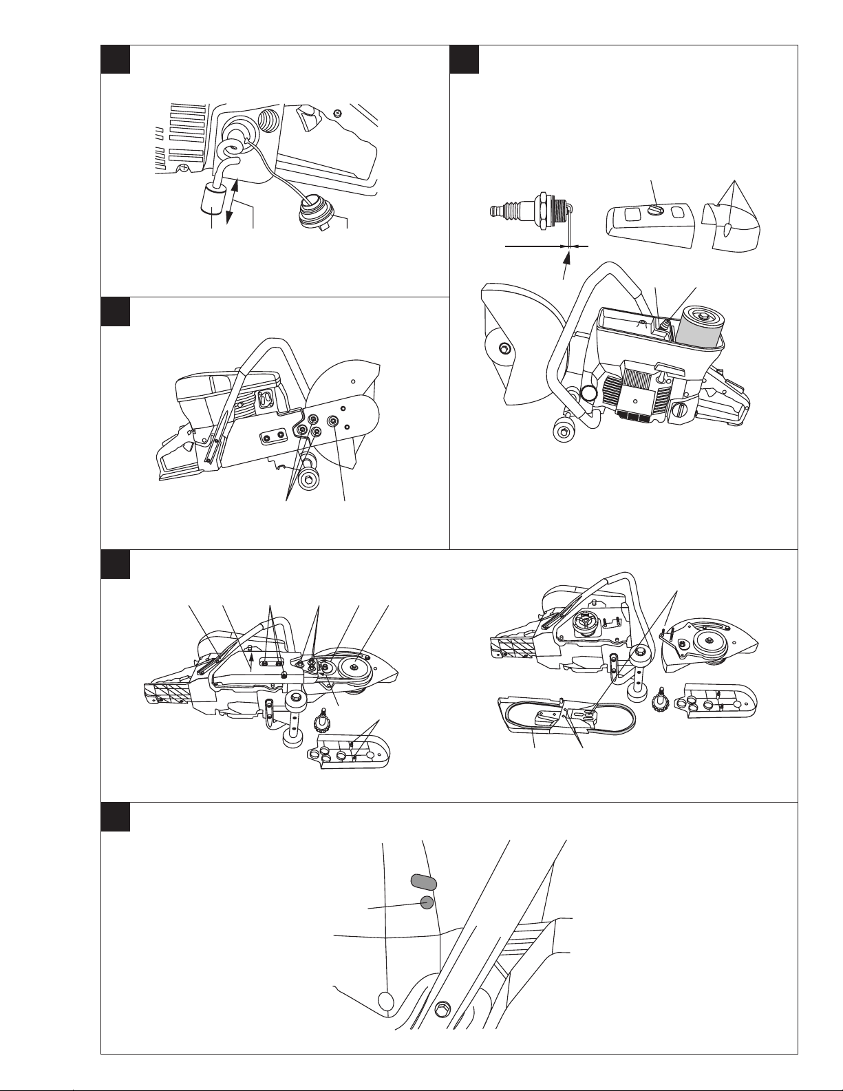
8.2.3 Replacing a broken starter rope
-NOTE-
Never shorten the starter rope as this could damage the starter housing.
1. Remove the four securing screws from the starter assembly.
2. Unscrew the 5 cross-recess screws and remove the cover plate.
3. Unscrew the two cross-recess screws as well as the securing screw and take
out the winding spool with the spring housing.
4. Remove the remaining piece of rope from the winding spool and the starter handle.
5. Insert the new rope into the rope spool.
6. Hold the spool against the clutch element and wind the starter rope counterclockwise tightly onto the spool taking the end of the rope down through the
slot in the spool.
7. Insert the spring housing with the spring upwards on the spool.
8. Attach the bent end of the spring to the slot at the spool pin and wind the spring
carefully into place (approx. 2 turns).
9. Hold the spool with the mounted spring housing upwards (the spring must
remain pretensioned) and fit the starter housing (make sure that the three lugs
of the spring housing engage in the three recesses of the starter housing).
10. Hold the spool against the clutch element (spring must remain pretensioned)
and secure it with the two cross-recess screws and the middle slotted screw.
11. Take the free end through the hole in the starter housing and, from below, through
the starter handle. Then tie a tight knot.
12. Secure the cover plate with the 5 cross-recess screws.
13. Place the starter assembly on the machine and press it down lightly. (Pulling on
the starter rope will engage the clutch and the starter assembly is fully installed.)
8.2.4 Inspecting and replacing the fuel filter
-NOTE-
● Check the fuel filter every month.
● When refueling the machine, take care to ensure that no dirt enters the fuel tank.
1. Open the fuel tank.
2. Remove the fuel filter from the fuel tank.
3. Check the fuel filter (it must be replaced if very dirty).
4. Put the fuel filter back in the fuel tank.
5. Close the fuel tank.
8.2.5 Cleaning the spark plug / setting the electrode gap and renewing the
spark plug
-NOTE-
● To gain access to the spark plug, the air pre-filter cover and the main air filter cov-
er must be removed.
● Use only spark plugs of the type Champion RCJ-7Y or another brand with the
same thermal value.
1. Open the cover, including the pre-filter, by turning the knob.
2. Remove the main filter cover.
3. Disconnect the spark plug connector lead.
4. Use a spark plug wrench to unscrew the spark plug from the engine.
8
5. If necessary, clean the electrode with a soft wire brush.
6. Check the electrode gap (0.5mm = 0.02") and adjust to the correct distance with
the aid of a feeler gauge.
7. Reconnect the spark plug connector lead, hold the thread on the spark plug
against the cylinder and pull the starter rope (press the decompression valve).
The ignition spark must be clearly visible. -CAUTION- Avoid touching the spark
plug electrode.
8. Use a spark plug wrench to screw the spark plug back into the motor.
9. Reconnect the spark plug connector lead.
10. Secure the main air filter cover.
11. Replace the cover including the pre-filter.
12. Secure the cover including the pre-filter by turning the hand screw.
8.2.6 Re-tensioning the V-belt
-NOTE-
● Check the tension of the V-belt after 3 – 4 running hours and daily thereafter.
1. Unscrew the three securing nuts.
2. Tension the belt by turning the tensioning cam clockwise (tension is correct when
the belt can be pressed down approx.
1
/2" by hand).
3. Tighten the three securing nuts.
8.2.6 Retensioning the DS HS80-16 drive belt
-NOTE-
● Check the belt tension after the machine has been refueled for approx. the 5th
time and then subsequently at daily intervals.
1. Slacken the two hex. nuts (13 mm AF) on the front section of the saw arm (do
not remove the nuts).
2. Release the lock nut on the belt tensioner.
3. Turn the belt tensioning screw (10 mm AF) until the end of the pressure pin is
positioned approximately in the center of the indicator opening.
4. Tighten the lock nut (10 mm AF) and the two hex. nuts (13 mm AF) securely.
5. Check again to ensure that all screws have been tightened securely and that the
belt is tensioned correctly.
8.2.7 Replacing the V-belt
1. Place the saw on its side. (Saw arm upwards)
2. Unscrew the two securing screws and remove the outer V-belt cover.
3. Turn the tensioning cam counterclockwise.
4. Remove the three securing nuts and spacers and take off the front part of the
saw arm.
5. Remove the three securing screws in the saw arm.
6. Lift off the rear part of the saw arm.
7. Remove the two securing screws for the inner V-belt cover and take off the inner
V-belt cover.
8. Place the new V-belt in the rear part of the saw arm and fit the inner V-belt cover.
9. Place the V-belt around the front pulley wheel and insert the three fixing pins
into the slots in the rear part of the saw arm.
10. Fit the spacers and securing nuts. (Do not tighten.)
11. Place the V-belt around the rear pulley wheel and insert the two studs into the
holes in the saw arm.
12. Mount the cylinder-head screw and the two hexagonal nuts (circlip ring facing
upwards) with washer.
13. Tension the belt by turning the tensioning cam clockwise (tension is correct
when the belt can be pressed down approx.
1
/2" by hand)
14. Tighten the three hexagonal nuts.
15. Mount the front belt cover and secure it in place with the cheese-head screws.
8.2.7 Replacing the DS HS80-16 drive belt
-NOTE-
● After carrying out this operation, check that the cutting disc can be turned easily
by hand and that all screws have been tightened securely.
1. PLay the machine on its side in a stable position (saw arm facing upwards).
2. Release the three hex. socket screws (4 mm) and washers and remove the plastic drive belt cover.
3. Slacken the two hex. nuts (13 mm AF) on the front section of the saw arm (do
not remove the nuts).
4. Release the lock nut (10 mm AF) on the belt tensioner and turn the tensioning
screw until the belt is completely slack.
5. Remove the belt from the front pulley (insert a small screwdriver between the
belt and the pulley and then rotate the pulley forwards by hand).
6. Remove the two hex. nuts (13 mm AF) and the hex. socket screw (4 mm ) from
the rear section of the saw arm and then remove the saw arm (note the position
of the washers).
7. Remove the two hex. nuts from the front section of the saw arm, separate the
two sections of the arm and remove the old drive belt.
8. Insert the new drive belt and then reconnect the two sections of the saw arm by
replacing the two hex. nuts (tighten the hex. nuts by hand, only finger tight).
9. Fit the drive belt onto the rear pulley and then secure the saw arm with the two
hex. nuts (13 mm AF) and the hex. socket screw (don’t forget the sheet metal
spacer and the washers).
10. Fit the drive belt onto the front pulley (position the belt in the groove and then
rotate the pulley forwards by hand).
11. Turn the belt tensioning screw until the end of the pressure pin is positioned
approximately in the center of the indicator opening. Secure the tensioning screw
by tightening the lock nut.
Page 15

12. Tighten the two hex. nuts (13 mm AF) on the front section of the saw arm securely.
13. Fit the front plastic drive belt cover and the three hex. socket screws (4 mm)
with washers.
14. Check again to ensure that all screws have been tightened securely and that the
belt is tensioned correctly.
8.2.8 Adjusting the carburetor
This engine has been designed and built in compliance with the exhaust emission
standards. The exhaust emission control system comprises the supply system, the
breather system and, above all, the carburetor.
-NOTE-
● Turn the adjuster screw over the permissible range of adjustment without apply-
ing force.
● The machine is fitted with a device which keeps the engine and thus also the cut-
ting disc below a certain maximum speed.
● Before adjusting the carburetor, the breather slots and the air filters must be
cleaned. The engine must also be run until it is warm.
Adjusting the idling speed (T) faster · slower
Set the idling speed so that there is a sufficient safety margin between idling speed
and clutch engagement speed.
8.3 Cleaning
-NOTE-
● Heavy deposits of dirt on the engine and in the cooling air apertures can lead to
dangerous overheating.
● A carefully cleaned machine is the best guarantee for fault-free, reliable opera-
tion.
● Do not permit foreign matter to enter internal parts of the machine.
● Do not use a steam pressure cleaning system or running water for cleaning.
● Do not use cleaning agents containing silicon.
1. After work, clean the cooling fins of the cylinder and the air breather openings
(starter assembly and air filter housing) using a brush or compressed air (make
sure that functioning of the pressure reducing valve is not restricted by dirt).
2. Clean all other parts of the machine with a soft brush and a damp cloth and make
sure that all operating components can be operated properly and easily.
3. Ensure that all grips are clean and free of oil and grease.
8.4 Maintenance
-WARNING-
● After cleaning and maintenance work, check that all protective devices are installed
and functioning correctly.
● Regularly inspect all external parts of the machine for damage and all operating
components for correct functioning. Do not operate the machine if parts are damaged and missing or if operating components do not function properly. Send in
the machine for repair to a Hilti service point or another specialist.
8.5 Transport in a vehicle
-WARNING-
● Before transporting the machine, allow it to cool completely to avoid the risk of
fire.
● If the saw is to be transported by a parcel service, the fuel tank must be fully
drained. We recommend that you use the original packaging for transportation
purposes if at all possible.
1. Remove the cutting disc.
2. Secure the machine to prevent it falling over, causing damage or spillage of fuel.
8.6 Storing the machine over a long period
-WARNING-
● Keep unused machines safely. Machines not in use should be kept in a dry, high-
up or locked place, out of the reach of children.
1. Drain the fuel tank and seal it with the filler cap.
2. Clean the machine thoroughly and grease the metal parts.
3. Store the cutting disc in a cool, dry place on a horizontal, flat surface.
4. Remove the spark plug.
5. Pour a small amount of oil into the cylinder.
6. Pour a small quantity of (type TC) oil into the cylinder.
7. Replace the spark plug.
8. Wrap the machine in plastic film.
9. Place the machine in the store.
en
9. Troubleshooting
Fault Possible cause Remedy
Cutting disc slows Cutting pressure to high or lateral cutting pressure. Reduce cutting pressure and hold the saw straight.
down or stops (Cutting disc jams in cut.)
completely whilst V-belt tension too low or broken. Re-tension or replace V-belt
cutting Cutting disc incorrectly fitted and tightened. Check mounting and tightening torque.
Excessive vibration, Cutting disc incorrectly fitted and tightened. Check mounting and tightening torque.
disc wanders off the Cutting disc damaged (unsuitable specification, cracks, missing Renew cutting disc.
cutting line segments, distorted, overheated, deformed, etc.).
Saw doesn’t start or Fuel tank empty (no fuel at carburetor). Fill fuel tank.
only with difficulty Spark plug wet. Close choke lever and repeat starting procedure several times.
Engine overheats Wrong fuel, engine oil too low or wrong type. Drain saw and flush out pipelines and tank, fill tank with correct fuel.
Incorrect cutting disc rotation direction (diamond cutting disc). Check rotation direction & change as required.
Damping rubber worn or loose. Renew damping rubber.
Dry spark plug and cylinder chamber (remove spark plug).
Dirty air filter. Clean or replace air filter.
Wrong fuel or water and dirt in tank. Flush fuel system through, replace fuel filter, renew fuel.
Air in fuel line (no fuel at carburetor). Bleed fuel line.
Dirty pressure equalizing filter. Clean or replace filter.
Dirty fuel filter (little or no fuel at carburetor). Clean tank and replace fuel filter.
No spark or only weak spark visible (with spark plug removed). Clean pitting marks off spark plug.
Check and reset electrode gap.
Renew spark plug.
Check ignition coil, cable, connectors and switch, replace as
required.
Insufficient compression. Repeat start with decompression valve closed.
Check engine compression and, if necessary, replace worn parts
(piston rings, piston, cylinder, etc.).
Very low temperatures. Warm up saw slowly to room temperature and repeat start proce-
dure.
Wrong spark plug. Renew spark plug (note correct specification).
Breather openings and cooling fins dirty. Clean breather openings and cooling fins.
9
Page 16

Fault Possible cause Remedy
Low engine power / Dirty air filter. Clean air filter and replace if required
saw power Only weak ignition sparks visible (with spark plug removed). Clean carbon build-up from spark plug.
en
Wrong, unsuitable or contaminated fuel. Flush out fuel system, renew filters and fill tank with correct fuel.
Unsuitable cutting disc specification for material to be cut. Change specification or contact Hilti Customer Service.
V-belt or cutting disc slipping. Check V-belt tension and cutting disc clamping and rectify any faults.
Low compression. Check compression and renew any worn parts.
Machine handled incorrectly (cutting pressure too high, cutting Use the saw in accordance with the operating instructions or contact
disc overheating, lateral jamming of cutting disc, unsuitable cutting Hilti Customer Service.
disc, etc.).
Engine speed too low. Check maximum speed and adjust (slight fluctuation at max. speed,
Machine is operated at a height in excess of 3,000 ft Adjust the carburetor.
(approx. 1,000 m) above sea level.
Mixture setting incorrect (fuel / air mixture). Check mixture setting and adjust (uniform no-load and immediate
Cutting disc rotates Idling speed too high. Check idling speed and adjust if necessary.
while machine is idling Centrifugal clutch defective. Replace the centrifugal clutch.
Check and reset electrode gap.
Renew spark plug.
Check ignition coil, cable, connectors and switch, replace as
required.
speed limitation responds).
throttle response).
10. Disposal
Most of the materials from which Hilti tools or machines are manufactured can be recycled. The materials must be correctly separated before they can be recycled. In
many countries, Hilti has already made arrangements for taking back your old machines or tools for recycling. Please ask your Hilti customer service department or
Hilti sales representative for further information.
Should you wish to return the machine or tool yourself to a disposal facility for recycling, proceed as follows: Dismantle the machine or tool as far as possible without
the need for special tools. Use absorbent paper to wipe oily parts clean and collect any oil or grease that runs out. This paper should also be disposed of correctly.
On no account should oil, grease or fuel be allowed to enter the waste water system or find its way into the ground.
Separate the individual parts as follows:
Part / assembly Main material Recycling
Covers Plastic* Plastics recycling
Gear housing Magnesium alloy Scrap metal
Cylinder and piston Aluminum alloy Scrap metal
Cutting disc guard Aluminum alloy Scrap metal
Saw arm Magnesium alloy Scrap metal
V-belt Plastic* Plastics recycling
Front grip Aluminum alloy Scrap metal
Fuel tank Plastic* Plastics recycling
Crankshaft and bearings Steel Scrap metal
Screws, small parts Steel Scrap metal
Cutting slurry **
** Plastic parts carry a mark indicating the material from which they are made.
** With regard to environmental aspects, allowing drilling slurry to flow directly into rivers, lakes or the sewerage system without suitable pre-treatment is problematical. Ask the local authorities for information about
applicable regulations.
We recommend the following pre-treatment:
Collect the cutting slurry (e.g. use a wet-type industrial vacuum cleaner).
Allow the slurry to settle and dispose of the solid material at a construction waste disposal site (the addition of a flocculent may accelerate the settling process).
Water from the cutting slurry (alkaline, ph value > 7) should be neutralized by adding an acidic neutralizing agent or large quantity of water before it is allowed to flow
into the sewerage system.
11. Federal emission control warranty statement
Your warranty rights and obligations
The U.S. Environmental Protection Agency (EPA), the California Air Resources Board
(CARB), and Hilti are pleased to explain the Emission Control System Warranty
applicable to your small non-road engine. In U.S. and Canada, small non-road
engines must be designed, built and equipped to meet the stringent federal antismog standards. The equipment engine must be free from defects in materials and
workmanship which cause it to fail to conform with U.S. EPA standards for the first
two years of engine use from the date of sale to the ultimate purchaser. Hilti must
warrant the emission control system on your small non-road engine for the periods of time listed above, provided there has been no abuse, neglect or improper
maintenance of your unit.
Your emission control system includes parts such as the carburetor and the ignition system.
Where a warrantable condition exists, Hilti will repair your small non-road engine
at no cost to you. Expenses covered under warranty include diagnosis, parts and
labor.
10
Manufacturer’s warranty coverage
All 2001 and later small non-road engines are warranted to meet the applicable EPA
and CARB requirements for two years. If any emission related part on your engine
(as listed above) is defective, the part will be repaired or replaced by Hilti.
Owner’s warranty responsibilities
As a small non-road engine owner, you are responsible for performance of the
required maintenance as defined by Hilti in the owner’s manual.
Hilti recommends that you retain all receipts covering maintenance on your small
non-road engine, but Hilti cannot deny warranty solely for the lack of receipts or for
your failure to ensure the performance of all scheduled maintenance. Any replacement part or service that is equivalent in performance and durability may be used
in non-warranty maintenance or repairs, and shall not reduce the warranty obligations of the engine manufacturer.
As the small non-road equipment engine owner, you should be aware, however,
that Hilti may deny you warranty coverage if your small non-road engine or a part
Page 17

of it has failed due to abuse, neglect, improper maintenance, unapproved modifications or the use of parts not made or approved by the original equipment manufacturer.
You are responsible for presenting your small non-road engine to Hilti as soon as
the problem exists. The warranty repairs should be completed in a reasonable
amount of time, not to exceed 30 days.
Coverage
Hilti warrants to the ultimate purchaser and each subsequent purchaser that your
small non-road equipment engine will be designed, built equipped, at the time of
sale, to meet all applicable regulations. Hilti also warrants to the initial purchaser
and each subsequent purchaser that the emission-related warranted parts are free
from defects in material and workmanship which cause the engine to fail to conform with applicable regulations for a period of two years.
These warranty periods will begin on the date small non-road equipment engine is
purchased by the initial purchaser. If any emission-related part on your engine is
defective, the part will be replaced by Hilti at no cost to the owner.
Hilti shall remedy warranty defects at authorized Hilti service and repair centers.
Any authorized work done at an authorized Hilti service and repair center shall be
free of charge to the owner if it is determined that a warranted part is defective. Any
manufacturer-approved or equivalent replacement part may be used for any warranty maintenance or repairs on emission-relate parts, and must be provided free
of charge to the owner if the part is still under warranty. Hilti is liable for damages
to other engine components caused by the failure of a warranted part still under
warranty.
12. Warranty
Hilti warrants that the machine supplied is free of defects in material and workmanship. This warranty is valid as long as the machine is operated and handled correctly, cleaned and serviced properly and in accordance with the Hilti operating
instructions, all warranty claims are made within 3 months from the date of the sale
(invoice date) (unless mandatory national regulations stipulate a longer minimum
period) and that the technical system is maintained, i.e. only original Hilti consumables, components and spare parts may be used with the machine. If the product
is purchased for hire or rental purposes the period of warranty is limited to 30 work
days. For parts of the ignition system the period of warranty is one (1) year.
This warranty covers the cost-free repair or replacement of defective parts. Parts
subject to normal wear (e.g. filters, V-belts, spark plugs, starter rope) as well as
repairs and adjustments made necessary as a result of contamination, humidity,
corrosion, damage caused by dropping, incorrect fuel or similar conditions are
excluded from this warranty.
Additional claims are excluded, unless stringent national rules prohibit such
exclusion. In particular, Hilti is not obligated for direct, incidental or consequential damages, losses or expenses in connection with, or by reason of, or
inability to use the machine for any purpose. Implied warranties of merchantability
or fitness for a particular purpose are specifically excluded.
If a defect is discovered, the machine and/or relevant parts must be returned immediately to the responsible Hilti marketing organization for repair or replacement.
This constitutes Hilti’s entire obligation with regard to warranty and supersedes all
prior or contemporaneous explanations and oral or written agreements concerning warranties.
The California Air Resources Board’s Emission Warranty Part List specifically defines
the emission related, warranted parts. These warranted parts are: the carburetor
assembly, coil assembly, rotor, spark plug, air filter, fuel filter, breather manifold and
the gaskets.
Maintenance requirements
The owner is responsible for performing the required maintenance as defined by
Hilti in the owner’s manual.
Limitations
The Emission Control Systems Warranty shall not cover any of the following:
a) repair or replacement required because of misuse, neglect or lack of required
maintenance,
b) repairs improperly performed or replacements not conforming to Hilti specifi-
cations that adversely affect performance and/or durability, and alterations or
modifications not recommended or approved in writing by Hilti, and
c) replacement of parts and other services and adjustments necessary for required
maintenance at and after this first scheduled replacement point. Except as set
forth above, the warranty terms set forth in section 12 below, apply.
en
11
Page 18

Hilti Corporation
*206873*
FL-9494 Schaan
Tel.:+423 /234 2111
Fax: +423 / 234 2965
www.hilti.com
Hilti = registered trademark of Hilti Corp., Schaan W 3082 1005 10-Pos. 3 1 Printed in Liechtenstein © 2005
Right of technical and programme changes reserved S. E. & O.
206873 / B
 Loading...