

Hill-Rom P8000, P8005, P8050, P8010, P8020 Service Manual
...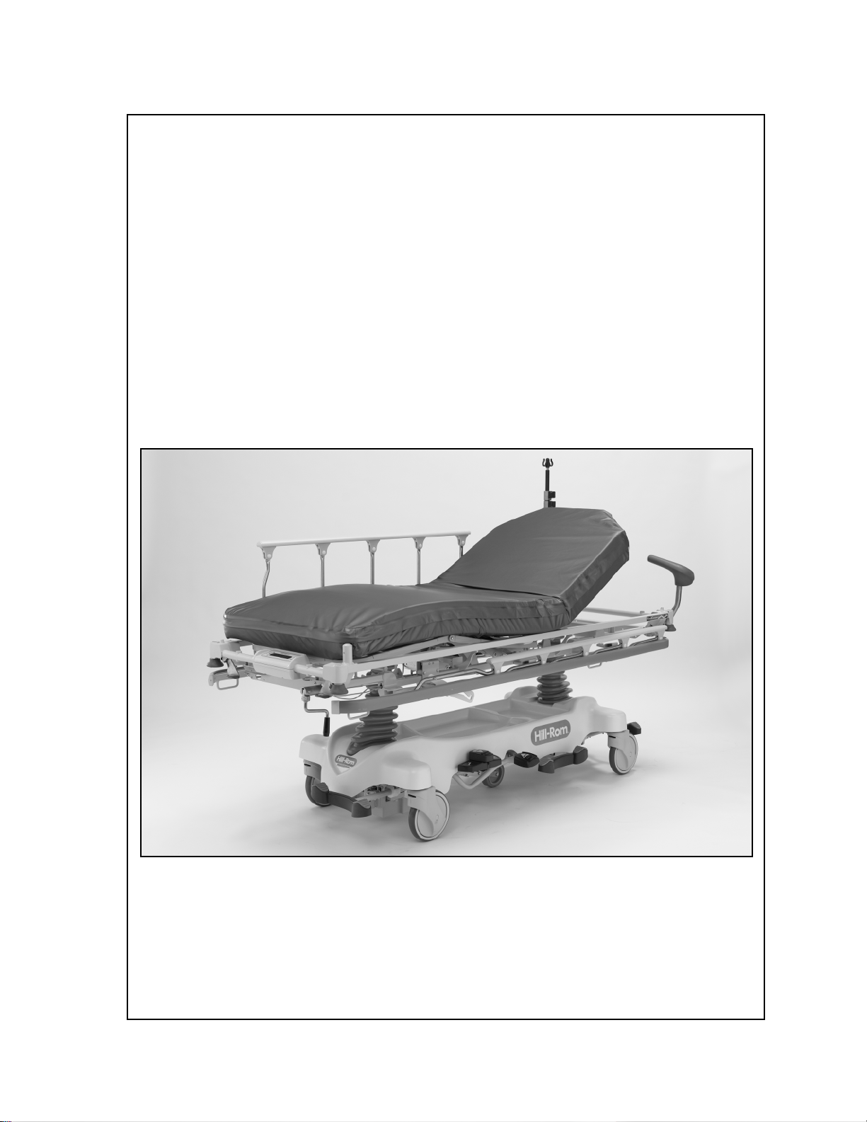
SERVICE MANUAL
Hill-Rom® Transport, Procedural, and Specialty Stretchers
Product No. P8000, P8005, P8010, P8020, P8040, P8050
144386 REV 2


© 2009 by Hill-Rom Services, Inc. ALL RIGHTS RESERVED.
Manufactured by:
HILL-ROM
1069 STATE ROUTE 46 E
BATESVILLE, IN 47006-9167
Authorized European Union Representative:
HILL-ROM SAS
B.P. 14 - Z.I. DU TALHOUET
56330 PLUVIGNER
FRANCE
TEL: +33 (0)2 97 50 92 12
No part of this text shall be reproduced or transmitted in any form or by any means,
electronic or mechanical, including photocopying, recording, or by any information or
retrieval system without written permission from Hill-Rom Services, Inc. (Hill-Rom).
The information in this manual is confidential and may not be disclosed to third parties
without the prior written consent of Hill-Rom.
Second Edition
First Printing 2007
Printed in the USA
Allen™ is a trademark of Industrial Fasteners, Inc.
Auto Contour™ is a trademark of Hill-Rom Services, Inc.
BackSaver Fowler® is a registered trademark of Hill-Rom Services, Inc.
Celcon® is a registered trademark of Hoechst Celanese Corporation.
Comfortline® is a registered trademark of Hill-Rom Services, Inc.
CSA® is a registered trademark of Canadian Standards Association, Inc.
Hill-Rom® is a registered trademark of Hill-Rom Services, Inc.
Loctite® is a registered trademark of Loctite Corporation.
Mechlok® is a registered trademark of P.L. Porter Company.
Hill-Rom® Transport, Procedural, and Specialty Stretchers
Service Manual (144386 REV 2) Page i
Oilite® is a registered trademark of Beemer Precision, Incorporated.
NOTE:
Resiten® is a registered trademark of L.C. Industries, Inc.
Steering Plus™ is a trademark of Hill-Rom Services, Inc.
Torx® is a registered trademark of Acument Intellectual Properties, LLC.
Ve l cr o® is a registered trademark of Velcro Industries, BV (a Dutch corporation).
The information contained in this manual is subject to change without notice. Hill-Rom
makes no commitment to update or keep current, the information contained in this
manual.
Hill-Rom reserves the right to make changes without notice in design, specifications, and
models. The only warranty Hill-Rom makes is the express written warranty extended on
the sale or rental of its products.
To order additional copies of this manual (144386), refer to the back cover for contact
information. For countries not listed on the back cover, contact your distributor.
The back cover is a comprehensive list of Technical Support contact information for
Hill-Rom. The product discussed in this manual may not be available in all of the
countries listed.
Revision Pages Affected Date
Original Issue January 2007
2 All February 2009
Page ii Hill-Rom® Transport, Procedural, and Specialty Stretchers
Service Manual (144386 REV 2)

Table of Contents
Chapter 1: Introduction
Purpose . . . . . . . . . . . . . . . . . . . . . . . . . . . . . . . . . . . . . . . . . . . . . . . . . . . . . . . . . . . 1-1
Audience . . . . . . . . . . . . . . . . . . . . . . . . . . . . . . . . . . . . . . . . . . . . . . . . . . . . . . . . . . 1-1
Reference Documents. . . . . . . . . . . . . . . . . . . . . . . . . . . . . . . . . . . . . . . . . . . . . . . . 1-1
Document Symbols. . . . . . . . . . . . . . . . . . . . . . . . . . . . . . . . . . . . . . . . . . . . . . . . . . 1-2
Specifications . . . . . . . . . . . . . . . . . . . . . . . . . . . . . . . . . . . . . . . . . . . . . . . . . . . . . . 1-3
Physical Description . . . . . . . . . . . . . . . . . . . . . . . . . . . . . . . . . . . . . . . . . . . . . . 1-3
Electrical Specification. . . . . . . . . . . . . . . . . . . . . . . . . . . . . . . . . . . . . . . . . . . . 1-6
Environmental Conditions . . . . . . . . . . . . . . . . . . . . . . . . . . . . . . . . . . . . . . . . . 1-6
Regulations, Standards, and Codes. . . . . . . . . . . . . . . . . . . . . . . . . . . . . . . . . . . 1-8
Electromagnetic Emissions and Immunity Guidance. . . . . . . . . . . . . . . . . 1-11
Model Identification . . . . . . . . . . . . . . . . . . . . . . . . . . . . . . . . . . . . . . . . . . . . . . . . 1-15
Safety Tips . . . . . . . . . . . . . . . . . . . . . . . . . . . . . . . . . . . . . . . . . . . . . . . . . . . . . . . 1-16
Warning and Caution Labels . . . . . . . . . . . . . . . . . . . . . . . . . . . . . . . . . . . . . . . . . 1-22
Chapter 2: Troubleshooting Procedures
Getting Started . . . . . . . . . . . . . . . . . . . . . . . . . . . . . . . . . . . . . . . . . . . . . . . . . . . . . 2-1
Initial Actions . . . . . . . . . . . . . . . . . . . . . . . . . . . . . . . . . . . . . . . . . . . . . . . . . . . . . . 2-1
Scale—Problem and Solution Table. . . . . . . . . . . . . . . . . . . . . . . . . . . . . . . . . . 2-2
Function Checks . . . . . . . . . . . . . . . . . . . . . . . . . . . . . . . . . . . . . . . . . . . . . . . . . . . . 2-3
Brake/Steer . . . . . . . . . . . . . . . . . . . . . . . . . . . . . . . . . . . . . . . . . . . . . . . . . . . . . 2-3
Hilow and Trendelenburg/Reverse Trendelenburg. . . . . . . . . . . . . . . . . . . . . . . 2-3
Siderail . . . . . . . . . . . . . . . . . . . . . . . . . . . . . . . . . . . . . . . . . . . . . . . . . . . . . . . . 2-4
Back Section—Procedural (without the Auto Cotour™ Feature),
Transport, Trauma, or OB/GYN Stretcher Only . . . . . . . . . . . . . . . . . . . . . . . . 2-4
Push Handles (Optional). . . . . . . . . . . . . . . . . . . . . . . . . . . . . . . . . . . . . . . . . . . 2-4
Active Brake System (Optional). . . . . . . . . . . . . . . . . . . . . . . . . . . . . . . . . . . . . 2-5
Permanent IV Pole (Optional) . . . . . . . . . . . . . . . . . . . . . . . . . . . . . . . . . . . . . . 2-5
Scale (Optional) . . . . . . . . . . . . . . . . . . . . . . . . . . . . . . . . . . . . . . . . . . . . . . . . . 2-5
Specific Function Checks—Procedural Stretcher. . . . . . . . . . . . . . . . . . . . . . . . . . . 2-6
Hill-Rom® Transport, Procedural, and Specialty Stretchers
Service Manual (144386 REV 2) Page iii

Knee Section (Optional)—Procedural Stretcher Only . . . . . . . . . . . . . . . . . . . . 2-6
Auto Contour™ Feature (Optional)—ON and Off (serial numbers (S/N)
before those that start with K). . . . . . . . . . . . . . . . . . . . . . . . . . . . . . . . . . . . . . . 2-6
Auto Contour™ (S/Ns that start with K and after) and BackSaver Fowler®
Features (Optional) . . . . . . . . . . . . . . . . . . . . . . . . . . . . . . . . . . . . . . . . . . . . . . . 2-6
Specific Function Checks—Surgical Stretcher. . . . . . . . . . . . . . . . . . . . . . . . . . . . . 2-7
Back Section . . . . . . . . . . . . . . . . . . . . . . . . . . . . . . . . . . . . . . . . . . . . . . . . . . . . 2-7
Headrest . . . . . . . . . . . . . . . . . . . . . . . . . . . . . . . . . . . . . . . . . . . . . . . . . . . . . . . 2-7
Specific Function Checks—Electric Stretcher . . . . . . . . . . . . . . . . . . . . . . . . . . . . . 2-7
Patient Controls (located on the siderails) . . . . . . . . . . . . . . . . . . . . . . . . . . . . . 2-7
Nurse Controls (located at the foot end of the stretcher) . . . . . . . . . . . . . . . . . . 2-9
Manual Back Section Articulation . . . . . . . . . . . . . . . . . . . . . . . . . . . . . . . . . . 2-10
Manual Knee Section Articulation . . . . . . . . . . . . . . . . . . . . . . . . . . . . . . . . . . 2-10
CPR Release . . . . . . . . . . . . . . . . . . . . . . . . . . . . . . . . . . . . . . . . . . . . . . . . . . . 2-10
Trauma Stretcher Function Checks. . . . . . . . . . . . . . . . . . . . . . . . . . . . . . . . . . . . . 2-11
Cassette Lift . . . . . . . . . . . . . . . . . . . . . . . . . . . . . . . . . . . . . . . . . . . . . . . . . . . 2-11
OB/GYN Stretcher Function Checks . . . . . . . . . . . . . . . . . . . . . . . . . . . . . . . . . . . 2-11
Foot Support . . . . . . . . . . . . . . . . . . . . . . . . . . . . . . . . . . . . . . . . . . . . . . . . . . . 2-11
Foot Section . . . . . . . . . . . . . . . . . . . . . . . . . . . . . . . . . . . . . . . . . . . . . . . . . . . 2-11
Final Actions. . . . . . . . . . . . . . . . . . . . . . . . . . . . . . . . . . . . . . . . . . . . . . . . . . . . . . 2-11
Reduced Braking Ability . . . . . . . . . . . . . . . . . . . . . . . . . . . . . . . . . . . . . . . . . . . . 2-12
Loss of Corner Steer . . . . . . . . . . . . . . . . . . . . . . . . . . . . . . . . . . . . . . . . . . . . . . . . 2-13
Steering Plus™ Steering System Does Not Operate Correctly . . . . . . . . . . . . . . . 2-14
Stretcher Will Not Go into Neutral Position. . . . . . . . . . . . . . . . . . . . . . . . . . . . . . 2-15
Reduced Pedal Pumps. . . . . . . . . . . . . . . . . . . . . . . . . . . . . . . . . . . . . . . . . . . . . . . 2-16
Stretcher Will Not Lower . . . . . . . . . . . . . . . . . . . . . . . . . . . . . . . . . . . . . . . . . . . . 2-17
Siderail Does Not Operate Correctly . . . . . . . . . . . . . . . . . . . . . . . . . . . . . . . . . . . 2-19
Procedural (without the Auto Contour™ Feature), Transport, Trauma,
or OB/GYN Stretcher—Back Section Does Not Raise or Lower Correctly . . . . . 2-20
Push Handle Malfunction . . . . . . . . . . . . . . . . . . . . . . . . . . . . . . . . . . . . . . . . . . . . 2-21
Permanent IV Pole Does Not Raise or Lower Correctly . . . . . . . . . . . . . . . . . . . . 2-22
Procedural or Surgical Stretcher—Knee Section Will Not Raise or Lower. . . . . . 2-23
Page iv Hill-Rom® Transport, Procedural, and Specialty Stretchers
Service Manual (144386 REV 2)

Scale Display Does Not Come On . . . . . . . . . . . . . . . . . . . . . . . . . . . . . . . . . . . . . 2-24
The Weight Shown on the Scale Display Is Not Correct . . . . . . . . . . . . . . . . . . . . 2-25
The Weight Shown on the Scale Display Is Flashing. . . . . . . . . . . . . . . . . . . . . . . 2-26
The Scale Display Flashes Hands Off, then CALC, and then ---- . . . . . . . . . . . . . 2-27
The Scale Display Flickers or Shows Partial Characters . . . . . . . . . . . . . . . . . . . . 2-28
Procedural Stretcher—Auto Contour™Feature with On/Off Controls
Does Not Raise or Lower Correctly . . . . . . . . . . . . . . . . . . . . . . . . . . . . . . . . . . . . 2-29
Procedural Stretcher—Auto Contour™ Feature or BackSaver Fowler®
Feature Does Not Raise or Lower Correctly . . . . . . . . . . . . . . . . . . . . . . . . . . . . . 2-30
Surgical Stretcher Back Section—Release Handle/Gas Spring Malfunction. . . . . 2-31
Surgical Stretcher Articulating Headrest—Push Handle Release/Gas
Spring Malfunction. . . . . . . . . . . . . . . . . . . . . . . . . . . . . . . . . . . . . . . . . . . . . . . . . 2-32
Electric Stretcher—Back Section Does Not Raise or Lower Electrically . . . . . . . 2-33
Electric Stretcher—Knee Section Does Not Raise or Lower Electrically . . . . . . . 2-34
Electric Stretcher Back Section—Manual Articulation . . . . . . . . . . . . . . . . . . . . . 2-35
Electric Stretcher Knee Section—Manual Articulation . . . . . . . . . . . . . . . . . . . . . 2-36
Trauma Stretcher Cassette Lift Handle Malfunction . . . . . . . . . . . . . . . . . . . . . . . 2-37
OB/GYN Stretcher—Foot Supports Malfunction . . . . . . . . . . . . . . . . . . . . . . . . . 2-38
OB/GYN Stretcher—Foot Section Does Not Release Correctly . . . . . . . . . . . . . . 2-40
Error 0 Shows on the Scale Display . . . . . . . . . . . . . . . . . . . . . . . . . . . . . . . . . . . . 2-41
Error 1 Shows on the Scale Display . . . . . . . . . . . . . . . . . . . . . . . . . . . . . . . . . . . . 2-42
Error 2 Shows on the Scale Display . . . . . . . . . . . . . . . . . . . . . . . . . . . . . . . . . . . . 2-43
Error 3 Shows on the Scale Display . . . . . . . . . . . . . . . . . . . . . . . . . . . . . . . . . . . . 2-44
Error 5 Shows on the Scale Display . . . . . . . . . . . . . . . . . . . . . . . . . . . . . . . . . . . . 2-45
Error 6 Shows on the Scale Display . . . . . . . . . . . . . . . . . . . . . . . . . . . . . . . . . . . . 2-46
Active Brake System—Reduced Braking Ability . . . . . . . . . . . . . . . . . . . . . . . . . 2-47
Chapter 3: Theory of Operation
Electrical System (Electric Stretcher). . . . . . . . . . . . . . . . . . . . . . . . . . . . . . . . . . . . 3-1
Control Board . . . . . . . . . . . . . . . . . . . . . . . . . . . . . . . . . . . . . . . . . . . . . . . . 3-1
Power Supply . . . . . . . . . . . . . . . . . . . . . . . . . . . . . . . . . . . . . . . . . . . . . . . . 3-1
Input Circuit . . . . . . . . . . . . . . . . . . . . . . . . . . . . . . . . . . . . . . . . . . . . . . . . . 3-2
Logic . . . . . . . . . . . . . . . . . . . . . . . . . . . . . . . . . . . . . . . . . . . . . . . . . . . . . . . 3-2
Comparator Circuit . . . . . . . . . . . . . . . . . . . . . . . . . . . . . . . . . . . . . . . . . . . . 3-2
Hill-Rom® Transport, Procedural, and Specialty Stretchers
Service Manual (144386 REV 2) Page v

LED Outputs. . . . . . . . . . . . . . . . . . . . . . . . . . . . . . . . . . . . . . . . . . . . . . . . . 3-3
Relay Outputs . . . . . . . . . . . . . . . . . . . . . . . . . . . . . . . . . . . . . . . . . . . . . . . . 3-3
Potentiometer Calibration Board . . . . . . . . . . . . . . . . . . . . . . . . . . . . . . . . . 3-3
Electric Stretcher Wiring Diagrams . . . . . . . . . . . . . . . . . . . . . . . . . . . . . . . . . . 3-4
Scale System (Optional for the Procedural, Electric, and Trauma Stretchers). . . . . 3-6
Load Beams . . . . . . . . . . . . . . . . . . . . . . . . . . . . . . . . . . . . . . . . . . . . . . . . . . . . 3-6
Scale P.C. Board . . . . . . . . . . . . . . . . . . . . . . . . . . . . . . . . . . . . . . . . . . . . . . . . . 3-6
Display P.C. Board . . . . . . . . . . . . . . . . . . . . . . . . . . . . . . . . . . . . . . . . . . . . . . . 3-7
Display Membrane Switch Panel . . . . . . . . . . . . . . . . . . . . . . . . . . . . . . . . . . . . 3-8
Chapter 4: Removal, Replacement, and Adjustment Procedures
Tool and Supply Requirements. . . . . . . . . . . . . . . . . . . . . . . . . . . . . . . . . . . . . . . . . 4-1
Procedural (P8000), Surgical (P8010), Trauma (P8040), or
OB/GYN (P8050) Stretcher—Siderail . . . . . . . . . . . . . . . . . . . . . . . . . . . . . . . . . . . 4-3
Switch the Procedural (P8000) or Trauma (P8040) Stretcher Siderail to the
Opposite Side of the Stretcher . . . . . . . . . . . . . . . . . . . . . . . . . . . . . . . . . . . . . . . . . 4-6
Electric (P8020) Stretcher—Siderail . . . . . . . . . . . . . . . . . . . . . . . . . . . . . . . . . . . . 4-7
Transport (P8005) Stretcher—Siderail Latch. . . . . . . . . . . . . . . . . . . . . . . . . . . . . 4-11
Transport (P8005) Stretcher—Siderail Tube . . . . . . . . . . . . . . . . . . . . . . . . . . . . . 4-13
Procedural (P8000), Surgical (P8010), Electric (P8020), Trauma (P8040),
or OB/GYN (P8050) Stretcher—Siderail Latch. . . . . . . . . . . . . . . . . . . . . . . . . . . 4-15
Procedural (P8000), Surgical (P8010), Electric (P8020), Trauma (P8040),
or OB/GYN (P8050) Stretcher—Siderail Tubes . . . . . . . . . . . . . . . . . . . . . . . . . . 4-17
OB/GYN (P8050) Stretcher—Patient Grip Handle . . . . . . . . . . . . . . . . . . . . . . . . 4-21
Electric (P8020) Stretcher—Left or Right Siderail Cable Assembly and
Upright Tube. . . . . . . . . . . . . . . . . . . . . . . . . . . . . . . . . . . . . . . . . . . . . . . . . . . . . . 4-23
Electric (P8020) Stretcher—Patient Control Switch . . . . . . . . . . . . . . . . . . . . . . . 4-27
Electric (P8020) Stretcher—Nurse Control Switch . . . . . . . . . . . . . . . . . . . . . . . . 4-29
Electric (P8020) Stretcher—Control Board . . . . . . . . . . . . . . . . . . . . . . . . . . . . . . 4-31
Electric Stretcher—Potentiometer . . . . . . . . . . . . . . . . . . . . . . . . . . . . . . . . . . . . . 4-34
Electric Stretcher—Power Cord Assembly . . . . . . . . . . . . . . . . . . . . . . . . . . . . . . 4-38
Procedural (P8000), Transport (P8005), Trauma (P8040), or
OB/GYN (P8050) Stretcher—Back Section Gas Spring . . . . . . . . . . . . . . . . . . . . 4-41
Surgical (P8010) Stretcher—Back Section Gas Spring . . . . . . . . . . . . . . . . . . . . . 4-45
Page vi Hill-Rom® Transport, Procedural, and Specialty Stretchers
Service Manual (144386 REV 2)

Surgical (P8010) Stretcher—Articulating Headrest Gas Spring . . . . . . . . . . . . . . 4-48
Procedural (P8000) or Surgical (P8010) Stretcher—Knee Screw Assembly. . . . . 4-51
Electric (P8020) Stretcher—Knee Drive Assembly . . . . . . . . . . . . . . . . . . . . . . . . 4-53
Electric (P8020) Stretcher—Head Drive Assembly . . . . . . . . . . . . . . . . . . . . . . . . 4-56
Electric (P8020) Stretcher—CPR Release Cable Assembly . . . . . . . . . . . . . . . . . 4-60
Upper Frame and Base Shroud . . . . . . . . . . . . . . . . . . . . . . . . . . . . . . . . . . . . . . . . 4-64
OB/GYN (P8050) Stretcher—Upper Frame Catch Shroud . . . . . . . . . . . . . . . . . . 4-69
OB/GYN Stretcher—Foot Support Mechlok® Device . . . . . . . . . . . . . . . . . . . . . 4-71
OB/GYN Stretcher—Foot Support Gas Spring . . . . . . . . . . . . . . . . . . . . . . . . . . . 4-74
Caster . . . . . . . . . . . . . . . . . . . . . . . . . . . . . . . . . . . . . . . . . . . . . . . . . . . . . . . . . . . 4-78
Caster Brake Adjustment . . . . . . . . . . . . . . . . . . . . . . . . . . . . . . . . . . . . . . . . . . . . 4-80
Brake/Steer Pedal Adjustment . . . . . . . . . . . . . . . . . . . . . . . . . . . . . . . . . . . . . . . . 4-81
Hydraulic Cylinder . . . . . . . . . . . . . . . . . . . . . . . . . . . . . . . . . . . . . . . . . . . . . . . . . 4-82
Steering Plus™ Steering System Assembly . . . . . . . . . . . . . . . . . . . . . . . . . . . . . . 4-88
Electric Stretcher—Fuse. . . . . . . . . . . . . . . . . . . . . . . . . . . . . . . . . . . . . . . . . . . . . 4-92
Scale—Batteries . . . . . . . . . . . . . . . . . . . . . . . . . . . . . . . . . . . . . . . . . . . . . . . . . . . 4-94
Scale—Load Beam . . . . . . . . . . . . . . . . . . . . . . . . . . . . . . . . . . . . . . . . . . . . . . . . . 4-96
Scale—Display or Scale P.C. Board. . . . . . . . . . . . . . . . . . . . . . . . . . . . . . . . . . . 4-109
Active Brake System . . . . . . . . . . . . . . . . . . . . . . . . . . . . . . . . . . . . . . . . . . . . . . 4-111
Active Brake System—Neutral Detent. . . . . . . . . . . . . . . . . . . . . . . . . . . . . . . . . 4-114
Stow-Away Push Handle (Stretchers with the Integrated
Oxygen Tank Storage) . . . . . . . . . . . . . . . . . . . . . . . . . . . . . . . . . . . . . . . . . . . . . 4-116
Chapter 5: Parts List
Service Parts Ordering . . . . . . . . . . . . . . . . . . . . . . . . . . . . . . . . . . . . . . . . . . . . . . . 5-1
Exchange Policy . . . . . . . . . . . . . . . . . . . . . . . . . . . . . . . . . . . . . . . . . . . . . . . . . . . . 5-3
In-Warranty Exchanges . . . . . . . . . . . . . . . . . . . . . . . . . . . . . . . . . . . . . . . . . . . 5-3
Out-of-Warranty Exchanges . . . . . . . . . . . . . . . . . . . . . . . . . . . . . . . . . . . . . . . . 5-4
Warranty . . . . . . . . . . . . . . . . . . . . . . . . . . . . . . . . . . . . . . . . . . . . . . . . . . . . . . . . . . 5-5
Recommended Spare Parts . . . . . . . . . . . . . . . . . . . . . . . . . . . . . . . . . . . . . . . . . . . . 5-7
Caster and Base Shroud . . . . . . . . . . . . . . . . . . . . . . . . . . . . . . . . . . . . . . . . . . . . . . 5-8
Base Assembly—Side Pedal. . . . . . . . . . . . . . . . . . . . . . . . . . . . . . . . . . . . . . . . . . 5-10
Base Assembly—Side Pedals with End Brake and Steer. . . . . . . . . . . . . . . . . . . . 5-14
Hill-Rom® Transport, Procedural, and Specialty Stretchers
Service Manual (144386 REV 2) Page vii

Base Assembly—End Pedals . . . . . . . . . . . . . . . . . . . . . . . . . . . . . . . . . . . . . . . . . 5-18
Base Assembly—Steering Plus™ Steering System . . . . . . . . . . . . . . . . . . . . . . . . 5-22
Upper Frame Assembly—Transport (P8005) Stretcher . . . . . . . . . . . . . . . . . . . . . 5-24
Upper Frame Assembly—Procedural (P8000) Stretcher . . . . . . . . . . . . . . . . . . . . 5-28
Upper Frame Panel Assembly—Procedural (P8000) Stretcher . . . . . . . . . . . . . . . 5-32
Upper Frame Assembly—Surgical (P8010) Stretcher . . . . . . . . . . . . . . . . . . . . . . 5-36
Surgical (P8010) Stretcher—Articulating Headrest . . . . . . . . . . . . . . . . . . . . . . . . 5-40
Upper Frame Assembly—OB/GYN (P8050) Stretcher (Sheet 1 of 2). . . . . . . . . . 5-42
Upper Frame Assembly—OB/GYN (P8050) Stretcher (Sheet 2 of 2). . . . . . . . . . 5-46
Upper Frame Panel Assembly—OB/GYN (P8050) Stretcher . . . . . . . . . . . . . . . . 5-48
Upper Frame Assembly—Trauma (P8040) Stretcher . . . . . . . . . . . . . . . . . . . . . . 5-52
Upper Frame Panel Assembly—Trauma (P8040) Stretcher. . . . . . . . . . . . . . . . . . 5-56
Upper Frame Labels—Trauma (P8040) Stretcher . . . . . . . . . . . . . . . . . . . . . . . . . 5-58
Upper Frame Assembly—Electric (P8020) Stretcher . . . . . . . . . . . . . . . . . . . . . . 5-60
Electric (P8020) Stretcher—Mattress Weldment . . . . . . . . . . . . . . . . . . . . . . . . . . 5-64
Electric (P8020) Stretcher—Head and Knee Drive Assembly. . . . . . . . . . . . . . . . 5-66
Electric (P8020) Stretcher—Head Drive/CPR Assemblies . . . . . . . . . . . . . . . . . . 5-68
Electric (P8020) Stretcher—Gearbox Assembly . . . . . . . . . . . . . . . . . . . . . . . . . . 5-70
Electric (P8020) Stretcher—Cable/Wire Routing . . . . . . . . . . . . . . . . . . . . . . . . . 5-72
Electric (P8020) Stretcher—Cable/Wire Assemblies. . . . . . . . . . . . . . . . . . . . . . . 5-74
Electric (P8020) Stretcher—Control Board Assembly (120 V AC
and 230 V AC) . . . . . . . . . . . . . . . . . . . . . . . . . . . . . . . . . . . . . . . . . . . . . . . . . . . . 5-76
Upper Frame—Auto Contour™ and BackSaver Fowler® Features
(S/Ns before J134AN7176 (sheet 1 of 2)) . . . . . . . . . . . . . . . . . . . . . . . . . . . . . . . 5-78
Upper Frame—Auto Contour™ and BackSaver Fowler® Features
(S/Ns before J134AN7176 (sheet 2 of 2)) . . . . . . . . . . . . . . . . . . . . . . . . . . . . . . . 5-80
Upper Frame—Auto Contour™ and BackSaver Fowler® Features
(S/Ns J134AN7176 and after (sheet 1 of 2)) . . . . . . . . . . . . . . . . . . . . . . . . . . . . . 5-84
Upper Frame—Auto Contour™ and BackSaver Fowler® Features
(S/Ns J134AN7176 through those that start with K (sheet 2 of 2)) . . . . . . . . . . . . 5-86
Upper Frame—Auto Contour™ and BackSaver Fowler® Features
(S/Ns that start with K and after) . . . . . . . . . . . . . . . . . . . . . . . . . . . . . . . . . . . . . . 5-90
Scale System. . . . . . . . . . . . . . . . . . . . . . . . . . . . . . . . . . . . . . . . . . . . . . . . . . . . . . 5-94
Page viii Hill-Rom® Transport, Procedural, and Specialty Stretchers
Service Manual (144386 REV 2)

Active Brake System . . . . . . . . . . . . . . . . . . . . . . . . . . . . . . . . . . . . . . . . . . . . . . . 5-96
Integrated Oxygen Tank Storage System . . . . . . . . . . . . . . . . . . . . . . . . . . . . . . . . 5-98
Stow-Away Push Handles and Utility Tray (stretchers with the
Integrated Oxygen Tank Storage). . . . . . . . . . . . . . . . . . . . . . . . . . . . . . . . . . . . . 5-100
Procedural (P8000) and Trauma (P8040) Stretchers—Siderail Assembly. . . . . . 5-102
Surgical (P8010) Stretcher—Siderail Assembly . . . . . . . . . . . . . . . . . . . . . . . . . 5-106
Electric (P8020) Stretcher—Siderail Assembly . . . . . . . . . . . . . . . . . . . . . . . . . . 5-110
OB/GYN (P8050) Stretcher Siderail—Assembly . . . . . . . . . . . . . . . . . . . . . . . . 5-114
IV Pole Module. . . . . . . . . . . . . . . . . . . . . . . . . . . . . . . . . . . . . . . . . . . . . . . . . . . 5-118
IV Pole . . . . . . . . . . . . . . . . . . . . . . . . . . . . . . . . . . . . . . . . . . . . . . . . . . . . . . . . . 5-120
Head/Footboard—P4120CT . . . . . . . . . . . . . . . . . . . . . . . . . . . . . . . . . . . . . . . . . 5-122
Convertible Footboard—P350CT. . . . . . . . . . . . . . . . . . . . . . . . . . . . . . . . . . . . . 5-124
IV Transporter—P491 . . . . . . . . . . . . . . . . . . . . . . . . . . . . . . . . . . . . . . . . . . . . . 5-126
Liquid Oxygen Tank Holder—P273. . . . . . . . . . . . . . . . . . . . . . . . . . . . . . . . . . . 5-128
Oxygen Tank Holder—P276 . . . . . . . . . . . . . . . . . . . . . . . . . . . . . . . . . . . . . . . . 5-129
Oxygen Tank Holder Bracket—P27604. . . . . . . . . . . . . . . . . . . . . . . . . . . . . . . . 5-130
Horizontal Oxygen Tank Holder—P27603 . . . . . . . . . . . . . . . . . . . . . . . . . . . . . 5-131
ISS Socket Adapter—P163. . . . . . . . . . . . . . . . . . . . . . . . . . . . . . . . . . . . . . . . . . 5-132
IV Pole—P2217 and ISS Transfer Pole—P158 . . . . . . . . . . . . . . . . . . . . . . . . . . 5-134
Security Straps—P349 . . . . . . . . . . . . . . . . . . . . . . . . . . . . . . . . . . . . . . . . . . . . . 5-136
Push Handles. . . . . . . . . . . . . . . . . . . . . . . . . . . . . . . . . . . . . . . . . . . . . . . . . . . . . 5-138
Armboard—P344AT . . . . . . . . . . . . . . . . . . . . . . . . . . . . . . . . . . . . . . . . . . . . . . 5-140
Stirrup Assembly—P347AT. . . . . . . . . . . . . . . . . . . . . . . . . . . . . . . . . . . . . . . . . 5-142
Trauma Stretcher Upright Chest Assembly—P279AT . . . . . . . . . . . . . . . . . . . . 5-144
Trauma Stretcher Lateral Cassette Holder—P264 . . . . . . . . . . . . . . . . . . . . . . . . 5-146
Surgical Stretcher PACU Extender—P261 . . . . . . . . . . . . . . . . . . . . . . . . . . . . . 5-148
Surgical Stretcher Head Positioning Strap—P449 . . . . . . . . . . . . . . . . . . . . . . . . 5-151
Surgical Stretcher Superior Wrist Rest—P262A01 . . . . . . . . . . . . . . . . . . . . . . . 5-152
Surgical Stretcher Temporal Wrist Rest—P262A02 . . . . . . . . . . . . . . . . . . . . . . 5-154
OB/GYN Stretcher Integrated Fiber Optic Exam Light—P7915AT . . . . . . . . . . 5-156
OB/GYN Stretcher Placenta Basin—P265. . . . . . . . . . . . . . . . . . . . . . . . . . . . . . 5-158
OB/GYN Stretcher Telescoping Calf Support—P35745AT . . . . . . . . . . . . . . . . 5-160
Hill-Rom® Transport, Procedural, and Specialty Stretchers
Service Manual (144386 REV 2) Pageix

Mattresses . . . . . . . . . . . . . . . . . . . . . . . . . . . . . . . . . . . . . . . . . . . . . . . . . . . . . . . 5-162
Chapter 6: General Procedures
Cleaning and Care. . . . . . . . . . . . . . . . . . . . . . . . . . . . . . . . . . . . . . . . . . . . . . . . . . . 6-1
General Cleaning . . . . . . . . . . . . . . . . . . . . . . . . . . . . . . . . . . . . . . . . . . . . . . . . 6-1
Steam Cleaning. . . . . . . . . . . . . . . . . . . . . . . . . . . . . . . . . . . . . . . . . . . . . . . . . . 6-2
Cleaning Hard to Clean Spots. . . . . . . . . . . . . . . . . . . . . . . . . . . . . . . . . . . . . . . 6-2
Disinfecting. . . . . . . . . . . . . . . . . . . . . . . . . . . . . . . . . . . . . . . . . . . . . . . . . . . . . 6-2
Spray Wash (Not applicable to Electric (P8020) Stretcher, OB/GYN
(P8050) Stretcher with the optional exam light installed) . . . . . . . . . . . . . . . . . 6-3
Mattress Draping (OB/GYN Stretcher) . . . . . . . . . . . . . . . . . . . . . . . . . . . . . . . 6-4
Component Handling (Electric Stretcher and Stretchers with the Scale Option). . . 6-4
P.C. Boards . . . . . . . . . . . . . . . . . . . . . . . . . . . . . . . . . . . . . . . . . . . . . . . . . . . . . 6-5
Preventive Maintenance . . . . . . . . . . . . . . . . . . . . . . . . . . . . . . . . . . . . . . . . . . . . . . 6-5
Preventive Maintenance Schedule . . . . . . . . . . . . . . . . . . . . . . . . . . . . . . . . . . . 6-6
Preventive Maintenance Checklist . . . . . . . . . . . . . . . . . . . . . . . . . . . . . . . . . . 6-13
Chapter 7: Accessories
Stretcher Accessories . . . . . . . . . . . . . . . . . . . . . . . . . . . . . . . . . . . . . . . . . . . . . . . . 7-1
Infusion Support System (ISS) Transfer Pole (P158). . . . . . . . . . . . . . . . . . . . . . . . 7-3
IV Pole (P2217) . . . . . . . . . . . . . . . . . . . . . . . . . . . . . . . . . . . . . . . . . . . . . . . . . . . . 7-4
Permanent IV Pole . . . . . . . . . . . . . . . . . . . . . . . . . . . . . . . . . . . . . . . . . . . . . . . . . . 7-5
Patient Tray (P490). . . . . . . . . . . . . . . . . . . . . . . . . . . . . . . . . . . . . . . . . . . . . . . . . . 7-6
Footboard (P4120CTM07) . . . . . . . . . . . . . . . . . . . . . . . . . . . . . . . . . . . . . . . . . . . . 7-7
Convertible Footboard (P350CT) . . . . . . . . . . . . . . . . . . . . . . . . . . . . . . . . . . . . . . . 7-8
IV Transporter (P491). . . . . . . . . . . . . . . . . . . . . . . . . . . . . . . . . . . . . . . . . . . . . . . 7-10
Oxygen Tank Holder (P27601). . . . . . . . . . . . . . . . . . . . . . . . . . . . . . . . . . . . . . . . 7-13
Liquid Oxygen Tank Holder (P273). . . . . . . . . . . . . . . . . . . . . . . . . . . . . . . . . . . . 7-14
Push Handles. . . . . . . . . . . . . . . . . . . . . . . . . . . . . . . . . . . . . . . . . . . . . . . . . . . . . . 7-15
Chart Holder (P361) . . . . . . . . . . . . . . . . . . . . . . . . . . . . . . . . . . . . . . . . . . . . . . . . 7-17
Transport Straps (P349) . . . . . . . . . . . . . . . . . . . . . . . . . . . . . . . . . . . . . . . . . . . . . 7-18
Utility Tray (P297A01/A02). . . . . . . . . . . . . . . . . . . . . . . . . . . . . . . . . . . . . . . . . . 7-19
Armboard (P344BT) . . . . . . . . . . . . . . . . . . . . . . . . . . . . . . . . . . . . . . . . . . . . . . . . 7-21
Upright Chest Cassette Holder (P279AT) . . . . . . . . . . . . . . . . . . . . . . . . . . . . . . . 7-23
Page x Hill-Rom® Transport, Procedural, and Specialty Stretchers
Service Manual (144386 REV 2)

Lateral Cassette Holder (P264). . . . . . . . . . . . . . . . . . . . . . . . . . . . . . . . . . . . . . . . 7-26
Ankle Stirrups (P347AT) . . . . . . . . . . . . . . . . . . . . . . . . . . . . . . . . . . . . . . . . . . . . 7-27
PACU Extender (P261) . . . . . . . . . . . . . . . . . . . . . . . . . . . . . . . . . . . . . . . . . . . . . 7-29
Superior Wrist Rest (P262A01) . . . . . . . . . . . . . . . . . . . . . . . . . . . . . . . . . . . . . . . 7-31
Temporal Wrist Rest (P262A02) . . . . . . . . . . . . . . . . . . . . . . . . . . . . . . . . . . . . . . 7-33
Gas Delivery System (P263). . . . . . . . . . . . . . . . . . . . . . . . . . . . . . . . . . . . . . . . . . 7-35
Head Positioning Strap (P449) . . . . . . . . . . . . . . . . . . . . . . . . . . . . . . . . . . . . . . . . 7-37
Placenta Basin (P265). . . . . . . . . . . . . . . . . . . . . . . . . . . . . . . . . . . . . . . . . . . . . . . 7-39
Telescoping Calf Supports (P35745AT). . . . . . . . . . . . . . . . . . . . . . . . . . . . . . . . . 7-41
Integrated Fiber Optic Exam Light (P7915AT) . . . . . . . . . . . . . . . . . . . . . . . . . . . 7-44
Headboard Assembly (P4120CT). . . . . . . . . . . . . . . . . . . . . . . . . . . . . . . . . . . . . . 7-51
Foot Extender Pad (P929G1/2). . . . . . . . . . . . . . . . . . . . . . . . . . . . . . . . . . . . . . . . 7-52
Hill-Rom® Transport, Procedural, and Specialty Stretchers
Service Manual (144386 REV 2) Pagexi

NOTES:
Page xii Hill-Rom® Transport, Procedural, and Specialty Stretchers
Service Manual (144386 REV 2)

Purpose
Audience
1
Chapter 1
Introduction
This manual contains instructions for the operation and maintenance of the
Hill-Rom® Transport, Procedural, and Specialty Stretchers. It also includes
parts lists (in chapter 5) for ordering replacement components.
This manual is intended for use by only facility-authorized persons. To ignore
this restriction can cause severe injury to people and serious damage to
equipment.
Reference Documents
For more information (such as operating instructions, features, and product
symbols), refer to the Hill-Rom® Transport Procedural, and Specialty
Stretchers User Manual (144385).
Hill-Rom® Transport, Procedural, and Specialty Stretchers Page 1 - 1
Service Manual (144386 REV 2)
Document Symbols
Chapter 1: Introduction
Document Symbols
This manual contains different typefaces and symbols to make the content
easier to read and understand:
• Standard text—used for regular data.
• Boldface text—emphasizes a word or phrase.
• NOTE:—sets apart special data or important instruction clarification.
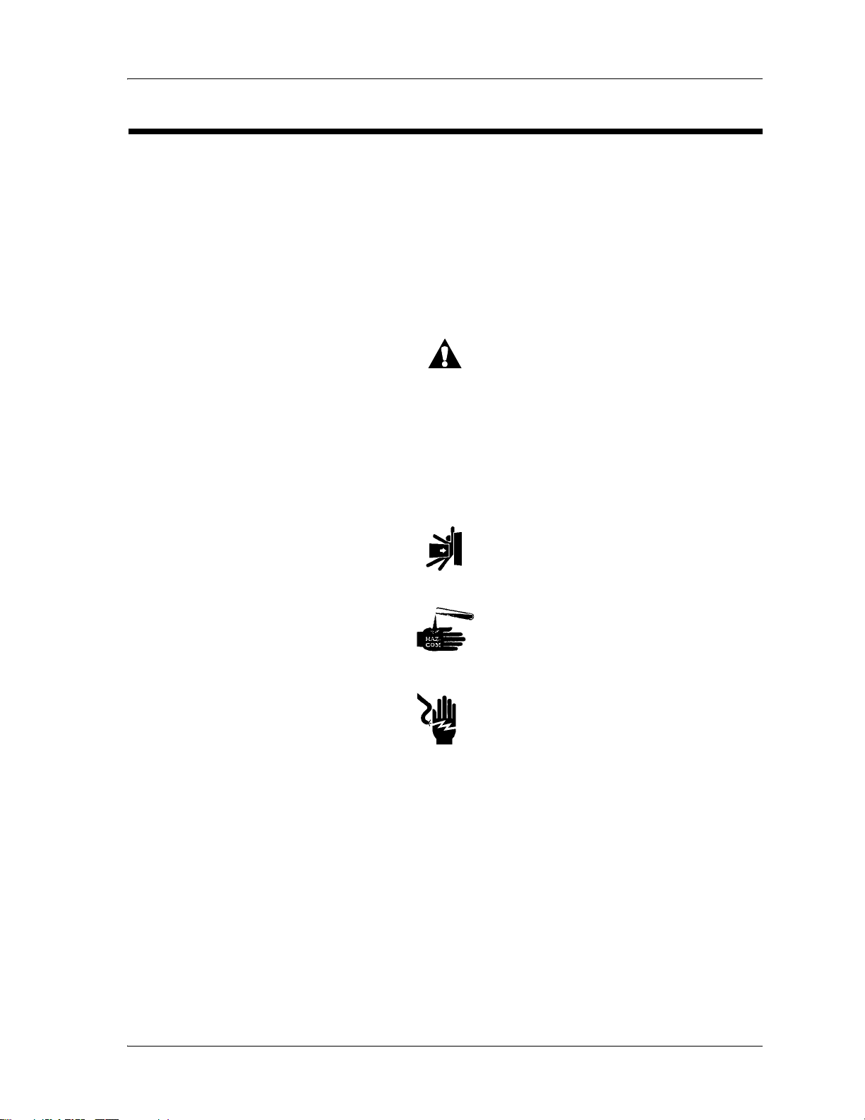
• WARNING or CAUTION
– A WARNING identifies situations or actions that may have an
– A CAUTION identifies special procedures or precautions that
effect on patient or user safety. To ignore a warning could cause
patient or user injury.
persons must obey to help prevent equipment damage.
• CAUGHT HAZARD WARNING
• CHEMICAL HAZARD WARNING
• ELECTRICAL SHOCK HAZARD WARNING
Page 1 - 2 Hill-Rom® Transport, Procedural, and Specialty Stretchers
Service Manual (144386 REV 2)

Specifications
Physical Description
Total Length
P8000, P8020, and P8040 83" (2108 mm)
P8010 92" (2337 mm)
P8050 80.5" (2045 mm)
Maximum Width (siderails stored)
P8000 29.25" (743 mm) or
P8005 30.375" (771.53 mm) or
Specifications
Chapter 1: Introduction
1
Feature Dimension
33.25" (845 mm)
34.375" (873.13 mm)
P8010 29.25" (743 mm)
P8020 and P8050 33.25" (845 mm)
P8040 29.25" (743 mm)
Maximum Width (siderails up)
P8000 32" (813 mm) or 36" (914 mm)
P8005 30.5" (775 mm) or
34.5" (876 mm)
P8010 and P8040 32" (813 mm)
P8020 and P8050 36" (914 mm)
Maximum Siderail Height above Sleep
Deck
P8000, P8010 and P8020 14.5" (368 mm)
P8005 14" (356 mm)
P8040 11" (279 mm)
P8050 13" (330 mm)
Siderail Length
P8000, P8005, P8010, P8020, and P8040 47" (1194 mm)
P8050 37" (940 mm)
Minimum Under-Stretcher Clearance 3.5" (89 mm) nominal
1.125" (29 mm) under the
hydraulic cylinders
Hill-Rom® Transport, Procedural, and Specialty Stretchers Page 1 - 3
Service Manual (144386 REV 2)

Specifications
Chapter 1: Introduction
Wheel Base (foot print) 24" x 50.5"
Mattress Dimensions
P8000 and P8005 26" x 75" (660 mm x 1905 mm)
P8010 26" x 78" (660 mm x 1981 mm)
P8020 30" x 75" (762 mm x 1905 mm)
P8040 26" x 75" (660 mm x 1905 mm)
P8050 30" x 72" (762 mm x 1829 mm)
Surface Thickness 3", 4", or 5"
Mattress Weight
Feature Dimension
(610 mm x 1283 mm)
or
29" x 73" (737 mm x 1854 mm)
(76 mm, 102 mm, or 127 mm)
3" (76 mm) mattress, standard 13.0 lb (5.9 kg)
3" (76 mm) mattress, wide 13.5 lb (6.1 kg)
4" (102 mm) mattress, standard 14.5 lb (6.6 kg)
4" (102 mm) mattress, wide 15.0 lb (6.8 kg)
5" (127 mm) Comfortline® Mattress,
12.0 lb (5.4 kg)
standard
5" (127 mm) Comfortline® Mattress,
15.5 lb (7.0 kg)
wide
OB/GYN mattress 14.0 lb (6.4 kg)
Caster Size 8" (203 mm) standard
Total Weight without Mattress,
No Accessories
P8000 and P8005 265.0 lb (120.2 kg)
P8010 285.0 lb (129.3 kg)
P8020 355.0 lb (161.0 kg)
P8040 290.0 lb (131.5 kg)
P8050 325.0 lb (147.4 kg)
Foot Section Inclination—P8020 (mini-
90°
mum)
Foot Support Inclination—P8050 70°
Page 1 - 4 Hill-Rom® Transport, Procedural, and Specialty Stretchers
Service Manual (144386 REV 2)

Specifications
Chapter 1: Introduction
Feature Dimension
Head Section Inclination (maximum) 90° (65° for P8020 with patient
controls; 80° for P8000 with
Automatic Contour; 70° for
P8010)
Knee Section Inclination (maximum)
P8005 and some P8000 N/A
P8010, P8020, and some P8000 25°
Sleep Surface Height, Lowest Position
P8000 20.5" (521 mm) with scale,
without integrated oxygen tank
storage system
22" (559 mm) with scale, with
integrated oxygen tank storage
system
20.7" (526 mm) without scale
1
P8005 23" (584 mm) (F and G models
built before July 2008)
20.5" (521 mm) (F and G mod-
els built after June 2008)
P8010 21.5" (546 mm)
P8020 22.5" (572 mm)
P8040 and P8050 24.25" (616 mm)
Sleep Surface Height, Highest Position
P8000, P8005, and P8020 34.25" (870 mm)
P8010 33.25" (845 mm)
P8040 37.5" (953 mm)
P8050 37" (940 mm)
Trendelenburg Position (maximum) 18°
Reverse Trendelenburg Position
(maximum)
Safe Working Load (includes patient
weight, accessories, and mattress)
18°
700 lb (317.5 kg)
Hill-Rom® Transport, Procedural, and Specialty Stretchers Page 1 - 5
Service Manual (144386 REV 2)

Specifications
Chapter 1: Introduction
Electrical Specification
120 V (P8020) Stretchers
Rated Voltage 120 V ~
Power/Input 7.0 A
Frequency 50/60 Hz
230 V Stretchers
Rated Voltage 230 V ~
Power/Input 3.0 A
Frequency 50/60 Hz
Exam Light (P8050 Stretcher)
Rated Voltage 120 V ~
Condition Range
Power/Input 400 mA
Frequency 50/60 Hz
Scale (P8000, P8020, and P8040
optional)
Environmental Conditions
Classification Standard
Transport and Storage—Stretchers
Temperature -40°F to 158°F (-40°C to 70°C)
Relative Humidity 20% to 95% non-condensing
Atmospheric Pressure 500 hPa to 1060 hPa
Transport and Storage—Exam Light
(P8050 Stretcher)
Temperature -4°F to 120°F (-20°C to 49°C)
Three AA, 1.5 V, alkaline
maximum
Relative Humidity 95% non-condensing maximum
Atmospheric Pressure 500 hPa to 1060 hPa
Use—Stretchers
Temperature 50°F to 95°F (10°C to 35°C)
ambient temperature
Page 1 - 6 Hill-Rom® Transport, Procedural, and Specialty Stretchers
Service Manual (144386 REV 2)
Specifications
Chapter 1: Introduction
Classification Standard
Relative Humidity 30% to 70% non-condensing
Atmospheric Pressure 700 hPa to 1060 hPa
Use—Exam Light (P8050 Stretcher)
Temperature 59°F to 104°F (15°C to 40°C)
ambient temperature
Relative Humidity 75% non-condensing maximum
Atmospheric Pressure 500 hPa to 1060 hPa
1
Hill-Rom® Transport, Procedural, and Specialty Stretchers Page 1 - 7
Service Manual (144386 REV 2)

Specifications
Chapter 1: Introduction
Regulations, Standards, and Codes
The Stretchers and the Exam Light (for the P8050) are designed and
manufactured in accordance with these equipment classifications and
standards:
Classification Standard
Stretchers
Technical and Quality Assurance Standards
Equipment Classification per IEC 60601-1
(P8020)
Degree of Protection Against Electric
Shock (P8020)
Classification according to EU Directive
93/42/EEC
Degree of Protection Against Ingress of
Water (P8020 and the Scale enclosure)
Degree of Protection Against the Presence
of Flammable Anaesthetic Mixtures
UL 60601-1
CSA®a C22.2 No. 601.1
EN 60601-1
IEC 60601-1-2 (P8020)
IEC 60601-2-38
IEC 60601-2-46 (P8010)
ISO 13485
ISO 14971
ISO 10993-1
ISO 10993-5
ISO 10993-10
Class I
Type B
Class I
IPX4
IEC 60529
Not for use with flammable anaesthetics
(P8020)
Mode of Operation (P8020) Continuous operation with intermittent cool-
ing
3 minutes On/15 minutes Off (120 V model)
3 minutes On/30 minutes Off (230 V model)
Sound Level (measured 1 meter from
< 52 dBA (P8020)
patient’s ear)
Exam Light (P8050 Stretcher)
Technical and Quality Assurance Standards
IEC 60601-1
UL 60601-1
CAN/CSA® C22.2 No. 601.1
IEC 60601-1-2 (radiated and conducted
emissions)
Equipment Classification per IEC 60601-1 Class I
Page 1 - 8 Hill-Rom® Transport, Procedural, and Specialty Stretchers
Service Manual (144386 REV 2)

Chapter 1: Introduction
Classification Standard
Specifications
1
Degree of Protection Against Electric
Shock
Classification according to EU Directive
93/42/EEC
Degree of Protection Against Ingress of
Water
Degree of Protection Against the Presence
of Flammable Anaesthetic Mixtures
Mode of Operation Continuous operation
Sound Level (measured 1 meter from
patient’s ear)
a. CSA® is a registered trademark of Canadian Standards Association, Inc.
Mattress Flammability Codes
Classification Standard
United States
P1430E, P1432E, P1433E, P1434E 16 CFR 1632, Standard for the Flammability
Not applicable
Not applicable
IPX0, ordinary equipment not rated for fluid
ingress
Not for use with flammable anaesthetics
Not applicable
of Mattresses and Mattress Pads
CAL TB-117, Requirements, Test Procedure
and Apparatus for Testing the Flame Retardance of Resilient Filling Materials Used in
Upholstered Furniture (foam)
CAL TB-129, Flammability Test Procedures
for Mattresses for Use in Public Buildings
CAL TB-603, Requirements and Test Procedure for Resistance of a Mattress/Box Spring
Set to a Large Open Flame
BFD IX-II, Boston Fire Department Mattress
Fire Test
Hill-Rom® Transport, Procedural, and Specialty Stretchers Page 1 - 9
Service Manual (144386 REV 2)

Specifications
Chapter 1: Introduction
Classification Standard
Europe
P1430I, P1432I, P1433I, P1434I BS EN 597-1: 1995, Furniture - Assessment
of the Ignitability of Mattresses and Upholstered Bed Bases; Part 1: Ignition Source:
Smouldering Cigarette (Mattresses only)
BS EN 597-2: 1995, Furniture - Assessment
of the Ignitability of Mattresses and Upholstered Bed Bases; Part 2: Ignition Source:
Match Flame Equivalent (Mattresses only)
BS 7177: 1996, Specification for Resistance
to Ignition of Mattresses, Divans and Bed
Bases (Mattresses only)
BS 6807: 1996, Methods of Test for Assessment of the Ignitability of Mattresses, Upholstered Divans and Upholstered Bed Bases
with Flaming Types of Primary and Secondary Sources of Ignition (Mattresses only)
UNI 9175, Reaction to fire of Upholstered
Furniture Subjected to the Action of a Small
Flame
Page 1 - 10 Hill-Rom® Transport, Procedural, and Specialty Stretchers
Service Manual (144386 REV 2)

Specifications
NOTE:
NOTE:
Chapter 1: Introduction
Electromagnetic Emissions and Immunity Guidance
The Hill-Rom® Transport, Procedural, and Specialty Stretchers are intended
for use in the electromagnetic environment specified in the tables below. The
customer or the user of the bed should make sure that it is used in such an
evironment.
Guidance and Manufacturer's Declaration—Electromagnetic Emissions
1
The P8020 model is intended for use in the electromagnetic environment specified below.
The customer or the user of the P8020 model should make sure
it is used in such an environment.
Emissions Test Compliance Electromagnetic Environment—Guidance
RF Emissions
CISPR 11
RF Emissions
CISPR 11
Harmonic
Emissions
IEC 61000-3-2
Voltage
Fluctuations/
Flicker Emissions
IEC 61000-3-3
Group 1 The model P8020 uses RF energy only for its
internal functions. Therefore, its RF emissions are
low and are not likely to cause any interference in
nearby electronic equipment.
Class A The model P8020 is suitable for use in all estab-
lishments other than domestic and those directly
connected to the public low-voltage power supply
network that supplies buildings used for domestic
purposes.
Not
applicable
Not
applicable
Immunity of light to EMC is not considered safety related.
The Exam Light (OB/GYN P8050 Stretcher) was not tested for EMC
immunity.
Hill-Rom® Transport, Procedural, and Specialty Stretchers Page 1 - 11
Service Manual (144386 REV 2)

Specifications
Chapter 1: Introduction
Guidance and Manufacturer's Declaration - Electromagnetic Immunity
The P8020 model is intended for use in the electromagnetic environment specified below.
The customer or the user of the P8020 model should make sure it is
used in such an environment.
Immunity Test
IEC60601
Test Level
Compliance
Level
Electromagnetic Environment—
Guidance
Electrostatic ± 6 kV Con- ± 6 kV Con- Floors should be wood, concrete,
Discharge (ESD) tact tact or ceramic tile. If floors are covIEC 61000-4-2 ± 8 kV Air ± 8 kV Air ered with synthetic material, the
relative humidity should be at
least 30%.
Radiated RF 3 Vrms 3 Vrms Portable and mobile RF communiIEC 61000-4-3 80 MHz to 80 MHz to cations equipment should not be
2.5 GHz 2.5 GHz used at close distances to the
P8020 stretcher. (See Note 2)
Electrical Fast ± 2 kV on ± 2 kV on Mains power quality should be
Transient/Burst Power Sup- Power Sup- that of a typical commercial or
IEC 61000-4-4 ply Lines
± 1 kV on
Input/ Output
Lines
ply Lines
± 1 kV on
Input/ Output
Lines
hospital environment.
Surge ± 1 kV Dif- ± 1 kV Dif- Mains power quality should be
IEC 61000-4-5 ferential
Mode (lineline)
± 2 kV Common Mode
(LineGround)
ferential
Mode (line-
that of a typical commercial or
hospital environment.
line)
± 2 kV Common Mode
(LineGround)
Conducted RF 3 Vrms 3 Vrms Portable and mobile RF communiIEC 61000-4-6 150 kHz to 150 kHz to cations equipment (cell phones)
80 MHz 80 MHz should not be used at close dis-
tances to the P8020 stretcher. (See
Note 2)
Power Frequency
Magnetic Fields
IEC 61000-4-8
3 A/m 3 A/m The power frequency magnetic
field should be measured in the
intended installation location to
assure it is sufficiently low.
Page 1 - 12 Hill-Rom® Transport, Procedural, and Specialty Stretchers
Service Manual (144386 REV 2)

Specifications
Chapter 1: Introduction
Guidance and Manufacturer's Declaration - Electromagnetic Immunity
1
The P8020 model is intended for use in the electromagnetic environment specified below.
The customer or the user of the P8020 model should make sure it is
used in such an environment.
Immunity Test
IEC60601
Test Level
Voltage Dips, Short < 5% U
Interrupts, and
Variations On
Power Supply
Lines
IEC 61000-4-11
(95% dip in (95% dip in
UT for 0.5 UT for 0.5
cycles) cycles)
< 40% U
(60% dip in
UT for 5
T
T
Compliance
Level
< 5% U
< 40% U
T
T
(60% dip in
UT for 5
Electromagnetic Environment—
Guidance
Mains power quality should be that
of a typical commercial or hospital
environment. If operation is
required during an extended power
outage or interruption, the model
P8020 should be switched to operate from the backup battery.
cycles) cycles)
< 70% U
T
< 70% U
T
(30% dip in (30% dip in
UT for 25 UT for 25
cycles) cycles)
< 5% U
T
< 5% U
T
(95% dip in (95% dip in
UT for 5 sec- UT for 5 sec-
onds) onds)
(See Note 1)
Note 1: UT is the AC mains voltage prior to application of the test level.
Note 2: The compliance levels in the ISM frequency range 150 kHz to 2.5 GHz are
intended to decrease the likelihood that mobile/portable communications equipment could
cause interference if it is inadvertently brought into the patient area. However, emission
limits, IEC 60601 test levels, and tests specified in IEC 60601-1-2:2001 do not address
electromagnetic compatibility of electrical equipment at very close distances. Always use
care when you use any electrical or RF equipment in the immediate patient area.
Hill-Rom® Transport, Procedural, and Specialty Stretchers Page 1 - 13
Service Manual (144386 REV 2)

Specifications
Chapter 1: Introduction
Recommended separation distances between portable and mobile RF
communications equipment and the P8020 Model
The P8020 model is intended for use in an electromagnetic environment in which radiated
RF disturbances are controlled. The customer or the user of the P8020 model can help
prevent electromagnetic interference by maintaining a minimum distance between portable
and mobile RF communications equipment (transmitters) and the P8020 model as
recommended below, according to the maximum output power of the communications
equipment.
Immunity Test
Rated maximum
IEC60601
Test Level
Separation distance according to frequency of transmitter, m
Compliance
Level
Electromagnetic Environment—
Guidance
output power of
transmitter, W
80 MHz to
800 MHz
150 kHz to
80 MHz
800 MHz to 2.5 GHz
d = 2.33√ P
d = 1.2√ P
d = 1.2√ P
0.01 0.12 0.12 0.233
0.1 0.38 0.38 0.74
1 1.2 1.2 2.33
10 3.8 3.8 7.4
100 12 12 23.3
For transmitters rated at a maximum output power not listed above, the recommended separation distance d in metres (m) can be estimated using the equation applicable to the frequency of the transmitter, where P is the maximum output power rating of the transmitter in
watts (W) according to the transmitter manufacturer.
NOTE 1: At 80 MHz and 800 MHz, the separation distance for the higher frequency range
applies.
NOTE 2: These guidelines may not apply in all situations. Electromagnetic propagation is
affected by absorption and reflection from structures, objects and people.
Calculations are based on V1=3Vrms, E1=3V/m.
Page 1 - 14 Hill-Rom® Transport, Procedural, and Specialty Stretchers
Service Manual (144386 REV 2)

Model Identification
Model Identification
Chapter 1: Introduction
1
Model Number
P8000 Procedural Stretcher
P8005 Transport Stretcher
P8010 Surgical Stretcher
P8020 Electric Stretcher
P8040 Trauma Stretcher
P8050 OB/GYN Stretcher
a. F and newer model stretchers have a 700 lb (318 kg) safe working load
and offer an optional scale on the Procedural, Electric, and Trauma
Stretchers.
a
Description
Hill-Rom® Transport, Procedural, and Specialty Stretchers Page 1 - 15
Service Manual (144386 REV 2)
Safety Tips
WARNING:
WARNING:
NOTE:
WARNING:
WARNING:
WARNING:
Chapter 1: Introduction
Safety Tips
To help prevent the risk of hospital bed fires, make sure facility personnel
follow the safety tips in the FDA Public Health Notification: Safety Tips for
Preventing Hospital Bed Fires. (US only)
Evaluate patients for entrapment risk according to facility protocol, and
monitor patients appropriately.
Evaluate patients for entrapment risk according to facility protocol, and
monitor patients appropriately. Make sure that all siderails are fully
latched when in the raised position. Failure to do either of these could
cause serious injury or death.
Siderails are intended to be a reminder to the patient of the unit’s edges, not a
patient-restraining device. When appropriate, Hill-Rom recommends that
medical persons determine the correct methods necessary to make sure a
patient remains safely in bed.
Only facility-authorized persons should service Hill-Rom® Stretchers.
Service done by unauthorized persons could cause personal injury or
equipment damage.
Fuses F1 and F3 protect the stretcher’s electrical system. For 120 V AC
power, a 7 A UL 198G time-lag fuse should be used. For 230 V AC, a
3 A IEC 127.3 time-lag fuse should be used. Refer to the assembly
drawing or schematic for the correct fuse. Failure to use the correct fuse
could cause personal injury.
Make sure to use the hydraulic cylinder with the correct part number for
the stretcher. The Surgical Stretcher uses a hydraulic cylinder that has
a slower descent rate. Failure to do so could cause personal injury.
Page 1 - 16 Hill-Rom® Transport, Procedural, and Specialty Stretchers
Service Manual (144386 REV 2)
 Loading...