


 Loading...
USER MANUAL
Advanta™ Bed
From Hill-Rom
Product No. P1600
© 2002 by Hill-Rom Services, Inc. ALL RIGHTS RESERVED.
No part of this text shall be reproduced or transmitted in any form or by any means, electronic or mechanical, including photocopying, recording, or by any information or retrieval system without written permission from Hill-Rom Services, Inc. (Hill-Rom).
Third Edition
First Printing 1999
Printed in the USA
Advanta™ is a trademark of Hill-Rom Services, Inc.
Comfortline Basic® is a registered trademark of Hill-Rom Services, Inc.
Comfortline Ultimate® is a registered trademark of Hill-Rom Services, Inc.
Hill-Rom® is a registered trademark of Hill-Rom Services, Inc.
PLEUR-EVAC® is a registered trademark of Deknatel, Inc.
SideCom® is a registered trademark of Hill-Rom Services, Inc.
ZoneAire® is a registered trademark of Hill-Rom Services, Inc.
The information contained in this manual is subject to change without notice. Hill-Rom makes no commitment to update or keep current, the information contained in this manual.
The only product warranty intended by Hill-Rom is the express, written warranty accompanying the bill of sale to the original purchaser. Hill-Rom makes no other warranty, express or implied, and in particular, makes no warranty of merchantability or fitness for a particular purpose.
Additional copies of this manual can be obtained from Hill-Rom.
To order additional copies of this manual, call (800) 445-3720 and place a parts order for part number usr017rb.
Revision Letter |
Pages Affected |
Date |
|
|
|
Original Issue |
|
December, 1999 |
|
|
|
A |
All |
April, 2001 |
|
|
|
B |
All |
September, 2002 |
|
|
|

Table of Contents
Typographical Conventions . . . . . . . . . . . . . . . 1
Introduction . . . . . . . . . . . . . . . . . . . . . . . . . . . . . 2
Technical Specifications . . . . . . . . . . . . . . . . . . 3
Patient Characteristics . . . . . . . . . . . . . . . . . . . . 3
Siderail and Footboard Controls . . . . . . . . . . . . 4
Caregiver Controls . . . . . . . . . . . . . . . . . . . . . . . 6
CPR Release . . . . . . . . . . . . . . . . . . . . . . . . . . . 6
Resetting the CPR . . . . . . . . . . . . . . . . . . . . 7
Central Brake and Steer . . . . . . . . . . . . . . . . . . 7
Braking . . . . . . . . . . . . . . . . . . . . . . . . . . . . . 8
Steering . . . . . . . . . . . . . . . . . . . . . . . . . . . . 8
Neutral . . . . . . . . . . . . . . . . . . . . . . . . . . . . . 9
Bed Functions . . . . . . . . . . . . . . . . . . . . . . . . . . 9
Bed Up/Bed Down (Hi-Lo) . . . . . . . . . . . . . . 9
Head Section . . . . . . . . . . . . . . . . . . . . . . . 10
Knee Section . . . . . . . . . . . . . . . . . . . . . . . 10
Trendelenburg/Reverse Trendelenburg . . . 11
Chair In/Chair Out . . . . . . . . . . . . . . . . . . . 11
Siderail Back Lighting . . . . . . . . . . . . . . . . 12
Night Light . . . . . . . . . . . . . . . . . . . . . . . . . 12
Sensor Control (Night Light) . . . . . . . . . . . 13
Lockout Controls . . . . . . . . . . . . . . . . . . . . . . . 13
Head Section Lockout . . . . . . . . . . . . . . . . 13
Knee Section Lockout . . . . . . . . . . . . . . . . 14
Hi-Lo Lockout . . . . . . . . . . . . . . . . . . . . . . . 14
All Motors Lockout . . . . . . . . . . . . . . . . . . . 14
On/Off Controls . . . . . . . . . . . . . . . . . . . . . . . . 14
TV/Radio On/Off (Optional) . . . . . . . . . . . . 15
Night Light . . . . . . . . . . . . . . . . . . . . . . . . . 15
For Special Assistance
Back Light . . . . . . . . . . . . . . . . . . . . . . . . . 15 Nurse Call (Optional) . . . . . . . . . . . . . . . . . . . . 16 Patient Position Monitor (PPM) (Optional) . . . . 16 PPM Operation for A Model Beds (P1600A) . . 17 Enable (Key) . . . . . . . . . . . . . . . . . . . . . . . 17 System Power . . . . . . . . . . . . . . . . . . . . . . 17 Modes of Operation . . . . . . . . . . . . . . . . . . 17 PPM Operation for B Model Beds (P1600B) . . 21 Enable (Key) . . . . . . . . . . . . . . . . . . . . . . . 21 System Power . . . . . . . . . . . . . . . . . . . . . . 21 Modes of Operation . . . . . . . . . . . . . . . . . . 21 Sleep Surface Controls (Optional) . . . . . . . . . . 24 ZoneAire® Sleep Surface . . . . . . . . . . . . . 25 Bed Scale (Optional) . . . . . . . . . . . . . . . . . . . . 26 Before Operating The Scale . . . . . . . . . . . 26 Turning the Scale On or Off . . . . . . . . . . . . 26 Zeroing the Scale . . . . . . . . . . . . . . . . . . . 26 Changing Items on the Bed . . . . . . . . . . . . 26 Changing the Unit of Measure . . . . . . . . . . 27 Manual Weight Adjustment . . . . . . . . . . . . 27 Indicators . . . . . . . . . . . . . . . . . . . . . . . . . . . . . 27 Head Angle Indicator . . . . . . . . . . . . . . . . . 27 Trendelenburg Angle Indicator . . . . . . . . . 27 Indicator Lights . . . . . . . . . . . . . . . . . . . . . 28
Standard Features . . . . . . . . . . . . . . . . . . . . . . |
29 |
Headboard . . . . . . . . . . . . . . . . . . . . . . . . . . . . 29
Footboard . . . . . . . . . . . . . . . . . . . . . . . . . . . . 29
Siderails . . . . . . . . . . . . . . . . . . . . . . . . . . . . . . 30
Foot Section . . . . . . . . . . . . . . . . . . . . . . . . . . 31
Hill-Rom Account Manager |
|
|
Phone |
|
Clinical Specialist |
|
Phone |
||
Field Service Technician |
Phone |
|||
Customer Service Representative |
|
Phone |
||
i

Table of Contents
Drainage Bag Holders . . . . . . . . . . . . . . . . . . . 32
Restraint Holders . . . . . . . . . . . . . . . . . . . . . . . 32
IV Pole . . . . . . . . . . . . . . . . . . . . . . . . . . . . . . . 33
Power Cord . . . . . . . . . . . . . . . . . . . . . . . . . . . 33
Equipment Bracket . . . . . . . . . . . . . . . . . . . . . 34
Manual Operation. . . . . . . . . . . . . . . . . . . . . . . 34
Optional Features . . . . . . . . . . . . . . . . . . . . . . . 35
Sleep Surfaces . . . . . . . . . . . . . . . . . . . . . . . . 35
Comfortline Ultimate® Mattress and
Comfortline Basic® Mattress . . . . . . . . . . . 35
ZoneAire® Sleep Surface . . . . . . . . . . . . . 35
Accessory AC Receptacle Option (120 V Beds
Only) . . . . . . . . . . . . . . . . . . . . . . . . . . . . . . . . 36
Accessories . . . . . . . . . . . . . . . . . . . . . . . . . . . . 37
Permanent IV Poles . . . . . . . . . . . . . . . . . . . . . 37
Utility Shelf . . . . . . . . . . . . . . . . . . . . . . . . . . . . 37
Oxygen Tank Holder . . . . . . . . . . . . . . . . . . . . 38
Patient Controls—Standard . . . . . . . . . . . . . . . 39
Bed Functions . . . . . . . . . . . . . . . . . . . . . . . . . 39
Head Section . . . . . . . . . . . . . . . . . . . . . . . 39
Knee Section . . . . . . . . . . . . . . . . . . . . . . . 39
Easy-Grip Siderails . . . . . . . . . . . . . . . . . . . . . 39
Patient Controls—Optional . . . . . . . . . . . . . . . 40
Nurse Call . . . . . . . . . . . . . . . . . . . . . . . . . . . . 40
Resetting the Pillow Speaker Connector . . 41
Lighting . . . . . . . . . . . . . . . . . . . . . . . . . . . . . . 41
Entertainment . . . . . . . . . . . . . . . . . . . . . . . . . 41
Channel Controls . . . . . . . . . . . . . . . . . . . . 42
Volume Controls . . . . . . . . . . . . . . . . . . . . 42
Safety . . . . . . . . . . . . . . . . . . . . . . . . . . . . . . . . . 43
Bed Positions . . . . . . . . . . . . . . . . . . . . . . . . . . 43
Siderails . . . . . . . . . . . . . . . . . . . . . . . . . . . . . . 43
Brakes . . . . . . . . . . . . . . . . . . . . . . . . . . . . . . . 43
Fluids . . . . . . . . . . . . . . . . . . . . . . . . . . . . . . . . 43
Electricity . . . . . . . . . . . . . . . . . . . . . . . . . . . . . 44
Lockout Controls . . . . . . . . . . . . . . . . . . . . . . . 44
Parts and Accessories . . . . . . . . . . . . . . . . . . . 44
Operating Precautions . . . . . . . . . . . . . . . . . . . 44
Transport . . . . . . . . . . . . . . . . . . . . . . . . . . . . . 45
Sleep Surface Mattress . . . . . . . . . . . . . . . . . . 45
General Cleaning/Disinfecting . . . . . . . . . . . . 46
Steam Cleaning . . . . . . . . . . . . . . . . . . . . . . . . 46 Cleaning Hard to Clean Spots . . . . . . . . . . . . . 46 Disinfecting . . . . . . . . . . . . . . . . . . . . . . . . . . . 46 Cleaning Sleep Surfaces . . . . . . . . . . . . . . . . . 47 Cleaning Medical Fluid Spills . . . . . . . . . . 47 Cleaning Blood and Excreta . . . . . . . . . . . 47 Damage to the Sleep Surface Ticking . . . . 47
Patient Education . . . . . . . . . . . . . . . . . . . . . . . |
48 |
ii

Typographical Conventions
Typographical Conventions
This manual contains different typefaces and icons designed to improve readability and increase understanding of its content. Note the following examples:
•Standard text—used for regular information.
•Boldface text—emphasizes a word or phrase.
•NOTE:—sets apart special information or important instruction clarification.
•The symbol below highlights a WARNING or CAUTION:
Warning and Caution
–A WARNING identifies situations or actions that may affect patient or user safety. Disregarding a warning could result in patient or user injury.
–A CAUTION points out special procedures or precautions that personnel must follow to avoid equipment damage.
•The symbol below highlights a CAUGHT HAZARD WARNING:
Caught Hazard Warning
•The symbol below highlights a CHEMICAL HAZARD WARNING:
Chemical Hazard Warning
•The symbol below highlights an ELECTRICAL SHOCK HAZARD WARNING:
Electrical Shock Hazard Warning
1
Introduction
Introduction
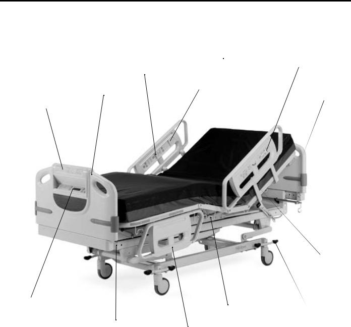
Optional ZoneAire® Mattress
Patient siderail control panels
Removable |
Speaker |
footboard |
|
Caregiver footboard control panel
Optional bed scale
Drainage bag holders
Optional permanent IV poles
Tuckaway siderails
Caregiver siderail control panels
Removable headboard (can be used for emergency CPR)
Removable
IV pole
Optional Patient
Position Monitoring
(PPM) system
Central Brake and Steer
with four-wheel braking
|
Table 1. Advanta™ Bed Model Numbers |
|
|
MODEL NUMBER |
DESCRIPTION |
|
|
P1600A |
Advanta™ Bed |
|
|
P1600B |
Advanta™ Bed with redesigned architecture for the |
|
new Patient Position Monitor. |
|
|
2

|
|
|
|
Technical Specifications |
|
|
|
|
|
|
|
|
Technical Specifications |
|
|
|
|
|
|
|
Table 2. Technical Specifications |
||
|
|
|
|
|
|
|
|
FEATURE |
|
DIMENSION |
|
|
|
|
|
|
|
|
|
Total length |
|
91” (231 cm) |
|
|
|
|
|
|
|
|
|
Retracted length |
|
78.5” (199.4 cm) |
|
|
|
|
|
|
|
|
|
Mattress support width |
|
35” (89 cm) |
|
|
|
|
|
|
|
|
|
Mattress support length |
|
83” (211 cm) |
|
|
|
|
|
|
|
|
|
Maximum width (siderails stored) |
|
36” (91 cm) |
|
|
|
|
|
|
|
|
|
Maximum width (siderails up) |
|
42.75” (108.6 cm) |
|
|
|
|
|
|
|
|
|
Maximum headboard height |
|
48” (122 cm) |
|
|
|
|
|
|
|
|
|
Maximum footboard height |
|
45” (114 cm) |
|
|
|
|
|
|
|
|
|
Maximum siderail height |
|
45” (114 cm) |
|
|
|
|
|
|
|
|
|
Power cord length (minimum) |
|
72” (183 cm) |
|
|
|
|
|
|
|
|
|
Minimum under-bed clearance |
|
4.75” (12.07 cm) |
|
|
|
|
|
|
|
|
|
Hi-Lo range |
|
13.25" (33.66 cm) |
|
|
|
|
|
|
|
|
|
Head section inclination (maximum) |
|
65° |
|
|
|
|
|
|
|
|
|
Knee section inclination (maximum) |
|
35° |
|
|
|
|
|
|
|
|
|
Automatic contour up (maximum) |
|
15° |
|
|
|
|
|
|
|
|
|
Automatic contour down |
|
28° |
|
|
|
|
|
|
|
|
|
Automatic contour (knee) |
|
10° |
|
|
|
|
|
|
|
|
|
Trendelenburg |
|
11° |
|
|
|
|
|
|
|
|
|
Reverse trendelenburg |
|
11° |
|
|
|
|
|
|
|
Patient Characteristics
•Height: 74" (188 cm) maximum, 54" (137 cm) minimum.
•Width: 36" (91 cm) maximum
•Weight: 500 lb (227 kg) maximum, 70 lb (32 kg) minimum*
*Includes mattress, IV pumps, poles, bags, etc. Accuracy of the scale may be diminished if the patient weighs more than 400 lb (181 kg). Mattress interface pressure performance may be diminished if the patient weighs more than 300 lb (136 kg).
WARNING:
Do not use the product outside the recommended patient height, width, and weight ranges. Patient injury or equipment damage may occur.
3

Siderail and Footboard Controls
Siderail and Footboard Controls
The head end siderails and the footboard contain most of the bed controls. The following tables list the caregiver controls for the siderails and footboard, and the patient controls for the siderails. The tables also indicate whether the item is standard or optional.
Caregiver Siderail Controls
LEFT HEAD END SIDERAIL |
RIGHT HEAD END SIDERAIL |
|
|
Standard |
|
Bed Up/Bed Down |
Bed Up/Bed Down |
Head Up/Head Down (without automatic contour) |
Head Up/Head Down (without automatic contour) |
Head Up/Head Down |
Head Up/Head Down |
Knee Up/Knee Down |
Knee Up/Knee Down |
Lockout Indicator |
Lockout Indicator |
Head Angle Indicator |
Head Angle Indicator |
Optional |
|
Nurse Call |
Nurse Call |
PPM Mode: Position, Exiting, Out of Bed |
|
PPM Exit Volume: Low, Med, High |
|
PPM Enable Control |
|
PPM Mode Indicators |
|
Brake Not Set Indicator |
|
Bed Not Down Indicator |
|
NOTE:
The caregiver siderail controls are on the outer sides of the head end siderails.
Patient Siderail Controls
LEFT HEAD END SIDERAIL |
RIGHT HEAD END SIDERAIL |
|
|
Standard |
|
Head Up/Head Down (with automatic contour) |
Head Up/Head Down (with automatic contour) |
Knee Up/Knee Down |
Knee Up/Knee Down |
Optional |
|
Nurse Call |
Nurse Call |
Nurse Call/Answer Indicators |
Nurse Call/Answer Indicators |
Room/Read Lights |
Room/Read Lights |
TV On/Off |
TV On/Off |
Channel Up/Down |
Channel Up/Down |
Radio On/Off |
Radio On/Off |
Select (Closed Captioned TV) |
Select (Closed Captioned TV) |
Volume Up/Down |
Volume Up/Down |
Speaker |
Speaker |
*PPM On/Off Indicator |
|
* This indicator is an unmarked light on the patient side of the left head end siderail.
NOTE:
The patient siderail controls are on the inner sides of the head end siderails.
4

Siderail and Footboard Controls
Caregiver Footboard Controls—Standard
ENTERTAINMENT AND LIGHTING
Siderail Back Lighting On/Off
Night Light On/Off
TV/Radio On/Off (Audio Mute)
SIDERAIL LOCKOUTS
Siderail Head
Siderail Knee
Siderail Hi-Lo
All Motors
BED POSITION CONTROLS
Bed Up/Bed Down
Trendelenburg/Reverse Trendelenburg
Chair In/Chair Out
INDICATORS
Motor Power Off
Ground Loss
Brake Not Set
Bed Not Down
Service Required
Trendelenburg/Reverse Trendelenburg Angle Indicator (mechanical gauge)
Caregiver Footboard Controls—Optional
SLEEP SURFACE SWITCHES
Auto Firm
Heel Relief 1 (ZoneAire® Sleep Surface only)
Heel Relief 2 (ZoneAire® Sleep Surface only)
Heel Relief 3 (ZoneAire® Sleep Surface only)
INDICATORS
Surface Power On/Off
Heel Relief Off
SCALE CONTROLS
Display On/Off
Lb/Kg
Zero/000.0
Change Items
Plus + (adjust weight)
Minus - (adjust weight)
5
Caregiver Controls
Caregiver Controls
CPR Release
The CPR Release allows the caregiver to save valuable time in an emergency situation. When activated, the CPR Release automatically lowers the head section of the bed to the flat position, enabling emergency procedures to be performed without unnecessary loss of time. After the head section is down, the knee section also comes down to the flat position. On beds equipped with an integrated air surface (ZoneAire® Sleep Surface), the Auto Firm function engages automatically when the CPR Release is activated. This provides a firm surface that supports a CPR board.
NOTE:
The headboard of the Advanta™ Bed can be used as a CPR board in emergencies.
Location: On both sides of the head section, near the head end of the bed.
To Activate: Press the red button on either side of the CPR Release handle, and pull the handle. Release your hand as the head section begins to come down.
WARNING:
If electrical power is lost, the head section still lowers, but the Auto Firm function does not engage. The optional air mattress maintains the same air pressure it had before power loss. The effectiveness of the CPR board may be reduced.
NOTE:
Emergency CPR Release Button
Emergency CPR Release Handle
If electrical power is lost, the air mattress maintains the same level of pressure it had at the time of power loss.
NOTE:
If electrical power is lost, the knee section, if raised, cannot be lowered.
NOTE:
Do not use the CPR Release to lower the head section in non-emergency situations. Use the Head Down controls located on the siderail.
NOTE:
After activating the CPR Release, allow 30 seconds for the head motor to resume its normal operating position before using the Head Up or Head Down controls.
6
Caregiver Controls
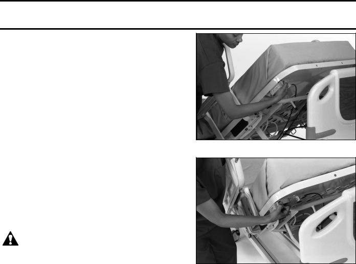
Resetting the CPR
If the head section stops lifting, but the head motor runs for a brief amount of time; the CPR needs to be reset.
WARNING:
Unplug the bed from its power source before inserting the IV rod for manual operation. Unexpected resumption of power can cause the IV rod to rotate and cause injury.
Location: Access hole at the head end of bed.
To Reset: Insert a Hill-Rom P2217 IV rod into the access hole at the head end of bed until it engages the roll pin in the end of the screw assembly.
•Push the IV rod hard enough to push the ejection spring back from the roll pin, allowing the IV rod to engage.
•Turn the IV rod clockwise until the screw assembly reaches its mechanical stop (you should hear a click).
NOTE:
The head section will not raise during this procedure.
IV Pole Insertion Points for Manual Operation
WARNING:
Remove the IV rod before plugging the bed into an appropriate power source. Resumption of power can cause the IV rod to rotate and cause injury.
•Remove the IV rod from the head screw assembly.
•Plug the bed into its appropriate power source.
•Hold the CPR release in the activated position until the motor stops running. The bed is now operational.
Central Brake and Steer
The Advanta™ Bed is equipped with 4-wheel braking and 2-wheel steering. The pedal controls can be accessed near the casters at each of the four corners of the bed.
Steering the Advanta™ Bed
7
Caregiver Controls
Braking
When the brakes are engaged, all four wheels lock, and the Brake Not Set indicators on the bed stop flashing. When the brakes are not engaged, the casters rotate, and the Brake Not Set indicators flash continuously.
Location: At each caster on the bed.
To Activate: At any wheel, push down fully on the orange pedal (the one closest to the head end of the bed). When the Brake Not Set indicator goes out, the brakes are locked.
CAUTION:
Unless the bed is about to be moved, the brakes should always be set and locked.
NOTE:
Central Brake and Steer—Braking
After setting the brakes, try to move the bed slightly to ensure that the brakes are locked.
NOTE:
When the brakes are not locked, the Brake Not Set indicators flash continuously.
Steering
The 2-wheel steering system locks both foot end casters in a straight position for easier transport.
Location: At each caster on the bed.
To Activate: At any wheel, push down fully on the green pedal (the one closest to the foot end of the bed). The Brake Not Set indicators will start to flash.
CAUTION:
Unless the bed is about to be moved, the brakes should always be set and locked.
NOTE:
When the brakes are not locked, the Brake Not Set indicators flash continuously.
NOTE:
Central Brake and Steer—Steering
During patient transport and in steer mode, push the Advanta™ Bed from the head end, using the headboard handles as hand holds.
8
Caregiver Controls
Neutral
In the neutral position, the swivels and casters move freely, allowing the bed to be moved in any direction. This function is used for exact positioning of the bed and maneuvering in confined areas
Location: At each caster on the bed.
To Activate: At any wheel, push either the orange or green pedal down slightly until the pedal is flat (in a horizontal position).
CAUTION:
Unless the bed is about to be moved, the brakes should always be set and locked.
NOTE:
When the brakes are not locked, the Brake Not Set indicators flash continuously.
Central Brake and Steer—Neutral
Bed Functions
The Advanta™ Bed is equipped with standard bed function controls on the caregiver side of each head end siderail, and at the footboard control panel. These controls operate all of the motor functions of the bed.
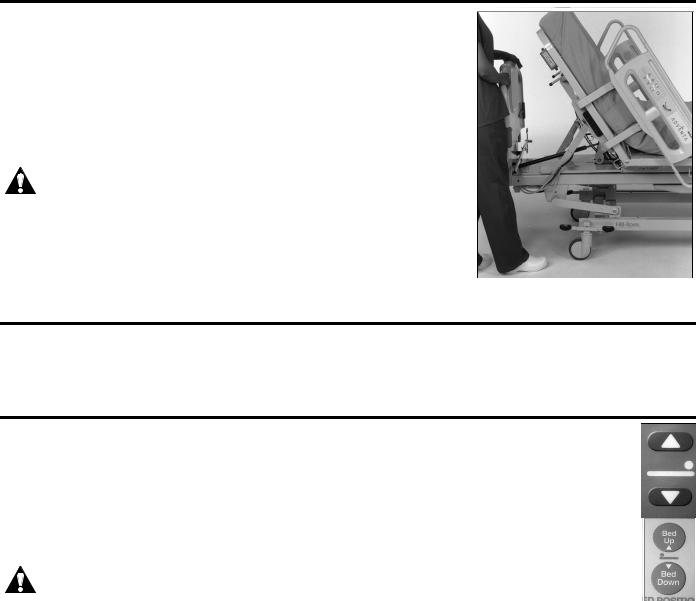
Bed Up/Bed Down (Hi-Lo)
The Bed Up/Bed Down controls allow you to raise or lower the bed 13.25" (33.65 cm). The low position is for general use and to assist with patient egress, while the high position is used for patient examinations.
Location: Outside left siderail, outside right siderail, footboard control panel.
To Activate: Press and hold the Bed Up key to raise the bed.
Press and hold the Bed Down key to lower the bed.
WARNING:
Leave the bed in the low position when the patient is unattended. This can reduce the possibility of patient falls and the severity of any resultant injuries.
NOTE:
The Bed Not Down indicator illuminates when the bed is not in the lowest position.
9
Caregiver Controls
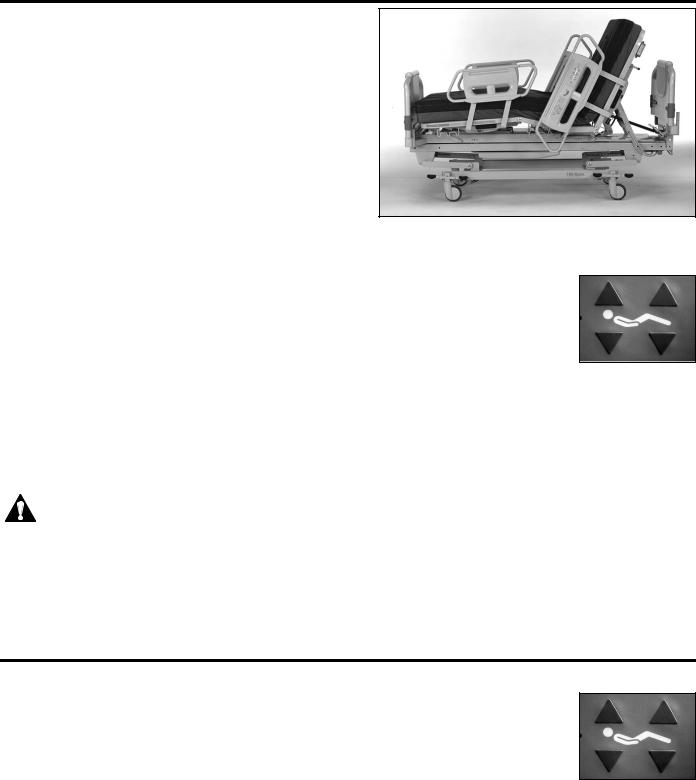
Head Section
The Head Up/Head Down controls enable you to raise or lower the head section of the bed. The head section of the bed can be raised to any desired angle of inclination up to 65°. Using the head angle indicator (see “Head Angle Indicator” on page 27), you can raise or lower the head section to specific desired angles.
Location: Outside left siderail, outside right siderail; left patient siderail, right patient siderail.
To Activate: Press and hold the Head Up key to raise the head section of the bed.
Press and hold the Head Down key to lower the head section of the bed.
NOTE:
Advanta™ Bed with Head Section Raised
Head Angle Indicators, located on the caregiver sides of the head end siderails, display the amount of head section angle in degrees.
NOTE:
For the caregiver’s convenience, the automatic contour function is only activated from the patient siderail controls.
NOTE:
When the Head Up control is activated from the patient siderail controls, the automatic contour function is activated. This raises the knee section automatically up to 15° when the Head Up function is activated. The automatic contour function helps keep the patient from sliding towards the foot end of the bed. This function is not activated from the caregiver controls, but is accessible to caregivers by using the patient siderail controls. Alternatively, the caregiver can simultaneously press the head up and knee up controls.
CAUTION:
Do not manually lift or lower the head section with the CPR release handle. If you do, the head section will not elevate properly until it is reset. Damage to the bed can occur when the head section is lifted with the CPR release handle.
If you manually raise or lower the head section while holding the CPR release in the activated position, the head section may not operate until you reset the CPR, refer to “Resetting the CPR” on page 7.
If the head section needs to be manually lifted or lowered, refer to “Manual Operation.” on page 34.
Knee Section
The Knee Up/Knee Down controls allow you to raise or lower the knee section of the bed to the desired angle of inclination, up to 35°.
Location: Outside left siderail, outside right siderail; left patient siderail, right patient siderail.
To Activate: Press and hold the Knee Up key to raise the knee section of the bed.
Press and hold the Knee Down key to lower the knee section of the bed.
10
Caregiver Controls
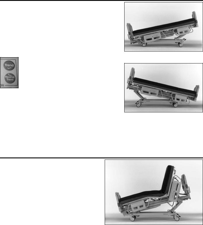
Trendelenburg/Reverse Trendelenburg |
|
The Advanta™ Bed can achieve up to 11° of Trendelenburg or |
|
Reverse Trendelenburg. You can activate the Trendelenburg and |
|
Reverse Trendelenburg controls at any bed height, and the bed |
|
adjusts its height as necessary. |
|
Location: Footboard control panel. |
|
To Activate: Press and hold the Trend key to place the bed into |
|
the Trendelenburg position. |
|
Press and hold the Reverse Trend key to place the |
|
bed into the Reverse Trendelenburg position. |
Trendelenburg |
NOTE:
A Trendelenburg Angle Indicator located on the footboard control panel displays the angle of Trendelenburg or Reverse Trendelenburg in degrees and inches.
NOTE: |
Reverse Trendelenburg |
When the Trendelenburg or Reverse Trendelenburg functions are
activated, the head and knee sections automatically return to the flat position.
NOTE:
When the Trendelenburg or Reverse Trendelenburg function is activated with the bed in the full low position, the bed automatically adjusts its height (rises slightly) enough to allow for full Trendelenburg or Reverse Trendelenburg articulation.
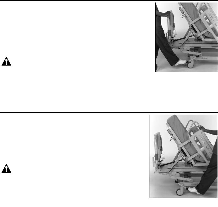
Chair In/Chair Out
When you activate the Chair In control, the bed automatically adjusts the head, knee, and hi-lo (head and foot) motors to position the bed in a “recliner chair” position.
Location: Footboard control panel.
Advanta™ Bed in the Chair Position
11
Caregiver Controls
To Activate: Press and hold the Chair In key to place the bed in the chair position.
Press and hold the Chair Out key to place the bed in the flat position.
NOTE:
The head, knee, and hilow functions may be used to articulate the bed out of the chair position. However, once the hilow function has been activated, the Chair Out function may not operate as described above.
WARNING:
To prevent personal injury, do not transport patients when the Advanta™ Bed is in the chair position.
WARNING:
Check periodically to ensure that the patient remains properly positioned. The use of pillows can help maintain side-to-side positioning.
WARNING:
For large patients or patients at risk for skin breakdown, use the Chair Out control to tilt the chair back some after attaining the chair position. This helps to optimize the interface pressure performance.
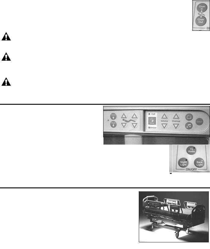
Siderail Back Lighting
The siderail back lights illuminate the controls and make the switches more visible in dim light. The back lighting can be turned on or off at the footboard control panel.
Location: Footboard control panel. |
|
Advanta™ Bed Siderail (Patient Side) |
||
|
|
|||
To Activate: Press and release the Back Light key |
|
|
|
|
|
|
|
|
|
to turn on or off the siderail backlighting. |
|
|
|
|
NOTE: |
|
|
|
|
The back light on the Nurse Call siderail control cannot be turned off. |
|
|
|
|
NOTE: |
|
|
|
|
|
|
|
||
|
|
|
|
Back Light Key |
When the green indicator light on the Back Light key is on, the function is active. |
|
|||
|
|
|||
Night Light
The night light is located on the bottom center of the bed frame. An adjustable light sensor can be set to turn the night light on when light in the room reaches a predetermined level of dimness.
Location: Footboard control panel.
To Activate: Press and release the Night Light key to turn on or off the night light.
Night Light
12
Caregiver Controls
When the green indicator light on Night Light key is on, the function is active.
Night Light Key
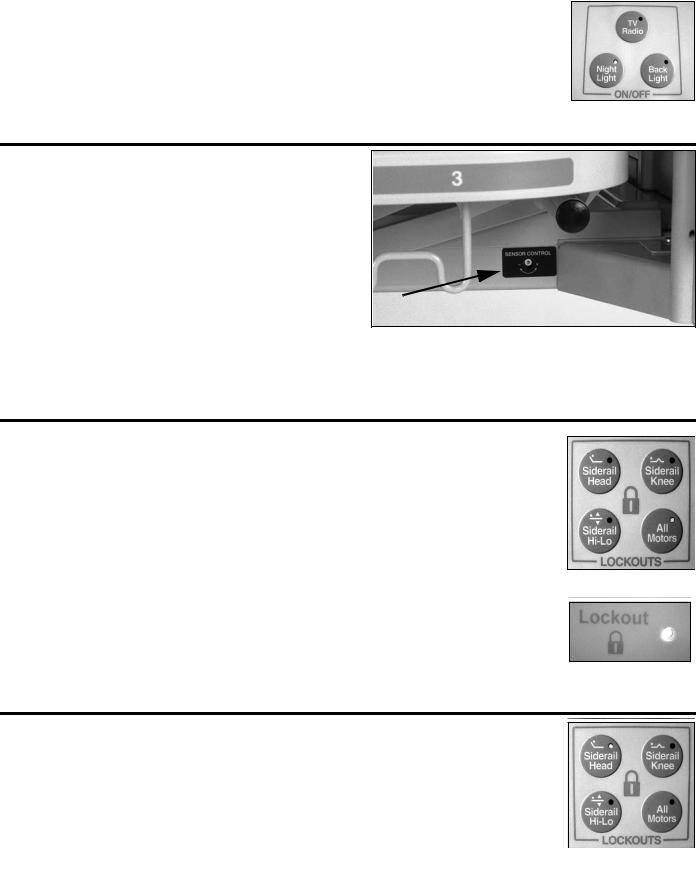
Sensor Control (Night Light)
The night light Sensor Control is located at the foot end of the bed frame, on the right-hand side. This control allows you to set the level of light at which the night light will come on. To increase the sensitivity, that is to turn the night light on when the room is less dark, turn the control counterclockwise. To decrease the sensitivity, that is to turn the night light on when the room is darker, turn the control clockwise.
Location: At the foot end of the bed frame, on the right-hand side.
Night Light Sensor Control
To Activate: Insert a small screwdriver into the hole in
the center of the Sensor Control. Turn the Sensor Control clockwise or counterclockwise, as desired.
Lockout Controls
Lockout controls lock certain articulating functions on the bed. This may be done to help ensure patient safety. When a lockout is activated, both the patient and caregiver controls for that function are disabled.
NOTE:
Activating the lockout functions does not affect the operation of the emergency CPR Release.
NOTE:
The All Motors lockout disables all bed articulation controls. No bed movement can occur, except for the emergency CPR Release.
NOTE:
When any lockout is activated, the yellow Lockout indicators on the caregiver siderail control panels illuminate.
Lockout Controls
Siderail Lockout
Indicator
Head Section Lockout
When activated, the Siderail Head lockout control disables the Head Up and Head Down movement of the bed.
Location: Footboard control panel.
To Activate: Press and release the Siderail Head lockout key.
To Deactivate: Press and release the Siderail Head lockout key.
Lockout Controls
NOTE:
When the Siderail Head function is locked out, the green light on the Siderail Head lockout key illuminates.
13
Loading...