

Hill-Rom P1190 User Manual
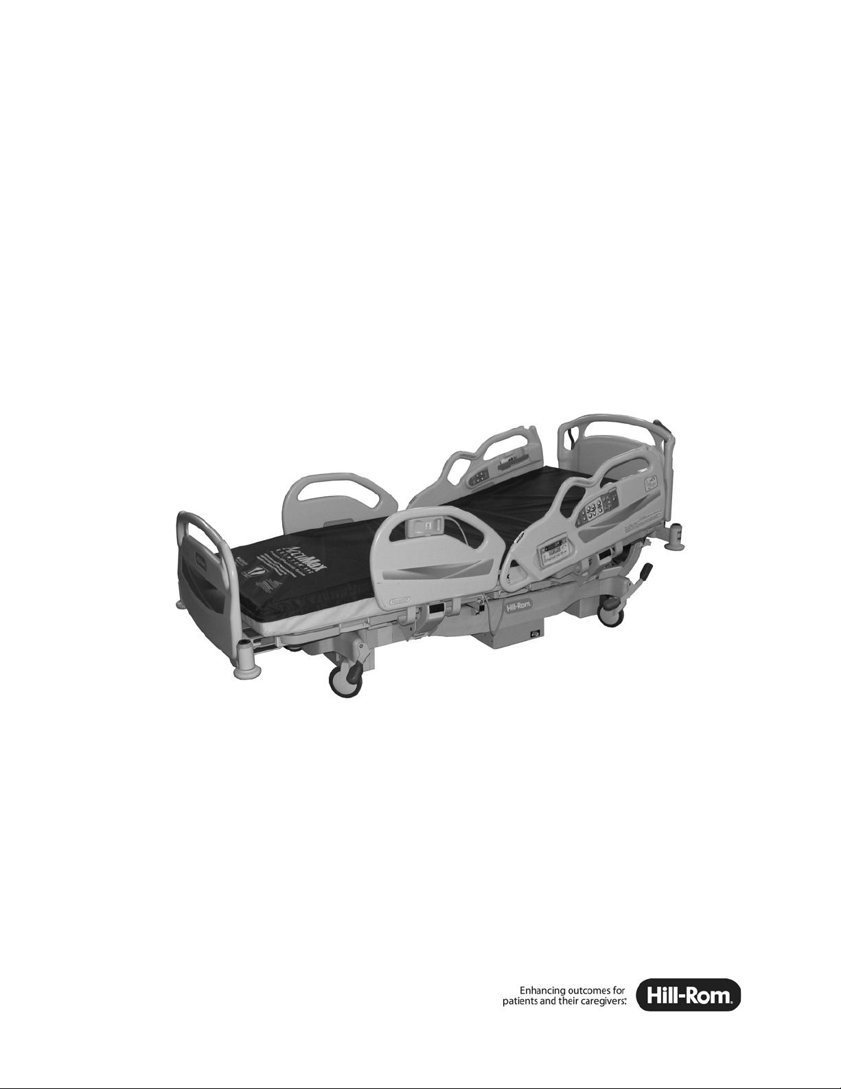
Advanta™ 2 Bed
157722 REV 2
User Manual
Product No. P1190


© 2015 by Hill-Rom Services, Inc. ALL RIGHTS RESERVED.
Manufactured by: Distributed by:
HILL-ROM DE MEXICO S. DE R.L. DE C.V.
AVEINDA DEL TELEFONE NO. 200 HUINALA
NUEVO LEON
HILL-ROM, INC.
1069 STATE ROUTE 46 E
BATESVILLE, IN 47006 USA
C.P. 66640 APODACA
MEXICO
No part of this text shall be reproduced or transmitted in any form or by any means,
electronic or mechanical, including photocopying, recording, or by any information or
retrieval system without written permission from Hill-Rom Services, Inc. (Hill-Rom).
The information in this manual is confidential and may not be disclosed to third parties
without the prior written consent of Hill-Rom.
The information contained in this manual is subject to change without notice.
Hill-Rom makes no commitment to update or keep current, the information contained in
this manual.
Hill-Rom reserves the right to make changes without notice in design, specifications, and
models. The only warranty Hill-Rom makes is the express written warranty extended on
the sale or rental of its products.
The Advanta™ 2 Bed product may be covered by one or more patents. For a list of
applicable patents, go to www.hill-rom.com/patents.
Second Edition, August 2015
First Printing 2009
CSA® is a registered trademark of Canadian Standards Association, Inc.
ETL® is a registered trademark of Intertek Testing Services NA, Inc.
Tempur-Pedic® is a registered trademark of Dan-Foam APS Corporation.
Advanta™, FreedomHill™, and LibertyHill™ are trademarks of Hill-Rom Services, Inc.
AccuMax®, Dining Chair®, Dynamic Air Therapy®, Envision®, FlexiCair Eclipse®,
FullChair®, Hill-Rom®, IntelliDrive®, Line-of-Site®, nano Ag+®, NaviCare®, Obstacle
Detect®
, PrimeAire®, SafeView®, Shearless Pivot®, SideCom®, Synergy®, V-CUE®,
and ZoneAire® are registered trademarks of Hill-Rom Services, Inc.
Replace this manual (157722) if it is damaged and/or can not be read.
For product support or to order additional copies of this manual (157722), contact your
distributor, local Hill-Rom representative, or go to www
.hill-rom.com.
Reference Documents
Advanta™ 2 Bed Service Manual (157723)
Advanta™ 2 Bed User Manual (157722 REV 2) i

ii Advanta™ 2 Bed User Manual (157722 REV 2)

Table of Contents
Document Symbols. . . . . . . . . . . . . . . . . . . . . . . . . . . . . . . . . . . . . . . . . . . . . . . . . . . . . 1
Intended Use . . . . . . . . . . . . . . . . . . . . . . . . . . . . . . . . . . . . . . . . . . . . . . . . . . . . . . . . . . 2
Introduction. . . . . . . . . . . . . . . . . . . . . . . . . . . . . . . . . . . . . . . . . . . . . . . . . . . . . . . . . . . 2
Features. . . . . . . . . . . . . . . . . . . . . . . . . . . . . . . . . . . . . . . . . . . . . . . . . . . . . . . . . . . . . . 3
Standard Features . . . . . . . . . . . . . . . . . . . . . . . . . . . . . . . . . . . . . . . . . . . . . . . . . . . . . . 4
Emergency CPR Control . . . . . . . . . . . . . . . . . . . . . . . . . . . . . . . . . . . . . . . . . . . . . 4
Caregiver Siderail Controls . . . . . . . . . . . . . . . . . . . . . . . . . . . . . . . . . . . . . . . . . . . 4
Lockout Control . . . . . . . . . . . . . . . . . . . . . . . . . . . . . . . . . . . . . . . . . . . . . . . . . . . . 5
Bed Up/Down Control . . . . . . . . . . . . . . . . . . . . . . . . . . . . . . . . . . . . . . . . . . . . . . . 5
Head Up/Down Control . . . . . . . . . . . . . . . . . . . . . . . . . . . . . . . . . . . . . . . . . . . . . . 5
Knee Up/Down Control . . . . . . . . . . . . . . . . . . . . . . . . . . . . . . . . . . . . . . . . . . . . . . 6
Foot Up/Down Control. . . . . . . . . . . . . . . . . . . . . . . . . . . . . . . . . . . . . . . . . . . . . . . 6
Trendelenburg and Reverse Trendelenburg Controls. . . . . . . . . . . . . . . . . . . . . . . . 6
Bed Flat Control . . . . . . . . . . . . . . . . . . . . . . . . . . . . . . . . . . . . . . . . . . . . . . . . . . . . 6
Dining Chair® Position . . . . . . . . . . . . . . . . . . . . . . . . . . . . . . . . . . . . . . . . . . . . . . 7
FullChair® Patient Positioning Mechanism. . . . . . . . . . . . . . . . . . . . . . . . . . . . . . . 7
Vascular Position . . . . . . . . . . . . . . . . . . . . . . . . . . . . . . . . . . . . . . . . . . . . . . . . . . . 8
Battery Control . . . . . . . . . . . . . . . . . . . . . . . . . . . . . . . . . . . . . . . . . . . . . . . . . . . . . 8
Brake and Steer Control . . . . . . . . . . . . . . . . . . . . . . . . . . . . . . . . . . . . . . . . . . . . . . 8
Head and Foot Siderails . . . . . . . . . . . . . . . . . . . . . . . . . . . . . . . . . . . . . . . . . . . . . . 9
Angle Indicators . . . . . . . . . . . . . . . . . . . . . . . . . . . . . . . . . . . . . . . . . . . . . . . . 10
30° Head Angle Alarm . . . . . . . . . . . . . . . . . . . . . . . . . . . . . . . . . . . . . . . . . . . 10
Line Manager . . . . . . . . . . . . . . . . . . . . . . . . . . . . . . . . . . . . . . . . . . . . . . . . . . 11
Patient Personal Storage . . . . . . . . . . . . . . . . . . . . . . . . . . . . . . . . . . . . . . . . . . 11
Care Grip Hand Hold . . . . . . . . . . . . . . . . . . . . . . . . . . . . . . . . . . . . . . . . . . . . 12
Headboard. . . . . . . . . . . . . . . . . . . . . . . . . . . . . . . . . . . . . . . . . . . . . . . . . . . . . . . . 12
Footboard . . . . . . . . . . . . . . . . . . . . . . . . . . . . . . . . . . . . . . . . . . . . . . . . . . . . . . . . 12
Patient Position Indicator . . . . . . . . . . . . . . . . . . . . . . . . . . . . . . . . . . . . . . . . . . . . 12
Equipment Sockets . . . . . . . . . . . . . . . . . . . . . . . . . . . . . . . . . . . . . . . . . . . . . . . . . 13
Foot Extension . . . . . . . . . . . . . . . . . . . . . . . . . . . . . . . . . . . . . . . . . . . . . . . . . . . . 13
Drainage Bag Holders. . . . . . . . . . . . . . . . . . . . . . . . . . . . . . . . . . . . . . . . . . . . . . . 13
Patient Restraint . . . . . . . . . . . . . . . . . . . . . . . . . . . . . . . . . . . . . . . . . . . . . . . . . . . 14
Standard Casters . . . . . . . . . . . . . . . . . . . . . . . . . . . . . . . . . . . . . . . . . . . . . . . . . . . 14
Advanta™ 2 Bed User Manual (157722 REV 2) iii

Standard Patient Controls . . . . . . . . . . . . . . . . . . . . . . . . . . . . . . . . . . . . . . . . . . . . 14
Pendant Controls. . . . . . . . . . . . . . . . . . . . . . . . . . . . . . . . . . . . . . . . . . . . . . . . 15
Siderail Controls . . . . . . . . . . . . . . . . . . . . . . . . . . . . . . . . . . . . . . . . . . . . . . . . 15
Automatic Contour Feature . . . . . . . . . . . . . . . . . . . . . . . . . . . . . . . . . . . . . . . . . . 15
Optional Features . . . . . . . . . . . . . . . . . . . . . . . . . . . . . . . . . . . . . . . . . . . . . . . . . . . . . 16
SideCom® Communication System. . . . . . . . . . . . . . . . . . . . . . . . . . . . . . . . . . . . 16
Nurse Call Control . . . . . . . . . . . . . . . . . . . . . . . . . . . . . . . . . . . . . . . . . . . . . . . . . 16
Enable Control . . . . . . . . . . . . . . . . . . . . . . . . . . . . . . . . . . . . . . . . . . . . . . . . . . . . 16
Bed Exit Alarm System . . . . . . . . . . . . . . . . . . . . . . . . . . . . . . . . . . . . . . . . . . . . . 17
Scale . . . . . . . . . . . . . . . . . . . . . . . . . . . . . . . . . . . . . . . . . . . . . . . . . . . . . . . . . . . . 19
Bed Setup . . . . . . . . . . . . . . . . . . . . . . . . . . . . . . . . . . . . . . . . . . . . . . . . . . . . . 19
Scale Display On/Off . . . . . . . . . . . . . . . . . . . . . . . . . . . . . . . . . . . . . . . . . . . . 20
Zero the Scale . . . . . . . . . . . . . . . . . . . . . . . . . . . . . . . . . . . . . . . . . . . . . . . . . . 20
Weigh the Patient . . . . . . . . . . . . . . . . . . . . . . . . . . . . . . . . . . . . . . . . . . . . . . . 20
Changing Items on the Bed. . . . . . . . . . . . . . . . . . . . . . . . . . . . . . . . . . . . . . . . 20
Manual Weight Adjustment . . . . . . . . . . . . . . . . . . . . . . . . . . . . . . . . . . . . . . . 20
Pounds/Kilograms. . . . . . . . . . . . . . . . . . . . . . . . . . . . . . . . . . . . . . . . . . . . . . . 20
Auxiliary Outlet (120 V Version Only) . . . . . . . . . . . . . . . . . . . . . . . . . . . . . . . . . 21
IntelliDrive® Transport System . . . . . . . . . . . . . . . . . . . . . . . . . . . . . . . . . . . . . . . 21
5th Wheel Assembly. . . . . . . . . . . . . . . . . . . . . . . . . . . . . . . . . . . . . . . . . . . . . . . . 23
NaviCare® Patient Safety Module . . . . . . . . . . . . . . . . . . . . . . . . . . . . . . . . . . . . . 24
SafeView® Alerts. . . . . . . . . . . . . . . . . . . . . . . . . . . . . . . . . . . . . . . . . . . . . . . . . . 24
Deactivate the SafeView® Alerts. . . . . . . . . . . . . . . . . . . . . . . . . . . . . . . . . . . 25
Configure the Siderails for the SafeView® Alerts . . . . . . . . . . . . . . . . . . . . . . 25
Optional Patient Controls . . . . . . . . . . . . . . . . . . . . . . . . . . . . . . . . . . . . . . . . . . . . 26
Nurse Call Control . . . . . . . . . . . . . . . . . . . . . . . . . . . . . . . . . . . . . . . . . . . . . . 26
Room Light Control . . . . . . . . . . . . . . . . . . . . . . . . . . . . . . . . . . . . . . . . . . . . . 26
Reading Light Control . . . . . . . . . . . . . . . . . . . . . . . . . . . . . . . . . . . . . . . . . . . 26
Volume Control . . . . . . . . . . . . . . . . . . . . . . . . . . . . . . . . . . . . . . . . . . . . . . . . 26
Channel Control . . . . . . . . . . . . . . . . . . . . . . . . . . . . . . . . . . . . . . . . . . . . . . . . 27
Music Control . . . . . . . . . . . . . . . . . . . . . . . . . . . . . . . . . . . . . . . . . . . . . . . . . . 27
Television Control . . . . . . . . . . . . . . . . . . . . . . . . . . . . . . . . . . . . . . . . . . . . . . 27
Obstacle Detect® System . . . . . . . . . . . . . . . . . . . . . . . . . . . . . . . . . . . . . . . . . . . . 27
Accessories . . . . . . . . . . . . . . . . . . . . . . . . . . . . . . . . . . . . . . . . . . . . . . . . . . . . . . . . . . 28
IV Pole (P2217) and Infusion Support System Transfer Pole (P158) . . . . . . . . . . 28
Mattress Foot Pad Extender . . . . . . . . . . . . . . . . . . . . . . . . . . . . . . . . . . . . . . . . . . 29
Mattress. . . . . . . . . . . . . . . . . . . . . . . . . . . . . . . . . . . . . . . . . . . . . . . . . . . . . . . . . . 29
Oxygen Tank Holder, E-Size (P27601) . . . . . . . . . . . . . . . . . . . . . . . . . . . . . . . . . 30
iv Advanta™ 2 Bed User Manual (157722 REV 2)

Traction Frame Support (P1181) . . . . . . . . . . . . . . . . . . . . . . . . . . . . . . . . . . . . . . 30
Patient Helper Support (P1191) . . . . . . . . . . . . . . . . . . . . . . . . . . . . . . . . . . . . . . . 30
Patient Helper (P1176 and P1177A). . . . . . . . . . . . . . . . . . . . . . . . . . . . . . . . . . . . 31
Patient Helper Positioning (P1177A) . . . . . . . . . . . . . . . . . . . . . . . . . . . . . . . . 32
VIP Headboard (P921190HA and P931190HA)
and Footboard (P921170FA and P931170FA). . . . . . . . . . . . . . . . . . . . . . . . . . . . 33
Safety Tips . . . . . . . . . . . . . . . . . . . . . . . . . . . . . . . . . . . . . . . . . . . . . . . . . . . . . . . . . . 34
Bed Positions . . . . . . . . . . . . . . . . . . . . . . . . . . . . . . . . . . . . . . . . . . . . . . . . . . 34
Brakes . . . . . . . . . . . . . . . . . . . . . . . . . . . . . . . . . . . . . . . . . . . . . . . . . . . . . . . . 34
Siderails/Restraints/Patient Monitoring . . . . . . . . . . . . . . . . . . . . . . . . . . . . . . 34
Electricity . . . . . . . . . . . . . . . . . . . . . . . . . . . . . . . . . . . . . . . . . . . . . . . . . . . . . 35
Electricity—Beds with an Auxiliary Outlet . . . . . . . . . . . . . . . . . . . . . . . . . . . 36
Parts and Accessories . . . . . . . . . . . . . . . . . . . . . . . . . . . . . . . . . . . . . . . . . . . . 37
Operating Bed/Surface Precautions . . . . . . . . . . . . . . . . . . . . . . . . . . . . . . . . . 37
Sleep Surface/Mattress . . . . . . . . . . . . . . . . . . . . . . . . . . . . . . . . . . . . . . . . . . . 37
Flammability. . . . . . . . . . . . . . . . . . . . . . . . . . . . . . . . . . . . . . . . . . . . . . . . . . . 38
Bed Articulations . . . . . . . . . . . . . . . . . . . . . . . . . . . . . . . . . . . . . . . . . . . . . . . 38
Chair Positioning . . . . . . . . . . . . . . . . . . . . . . . . . . . . . . . . . . . . . . . . . . . . . . . 38
Visitor Notification. . . . . . . . . . . . . . . . . . . . . . . . . . . . . . . . . . . . . . . . . . . . . . 38
Transport. . . . . . . . . . . . . . . . . . . . . . . . . . . . . . . . . . . . . . . . . . . . . . . . . . . . . . 38
Transport Position. . . . . . . . . . . . . . . . . . . . . . . . . . . . . . . . . . . . . . . . . . . . . . . 39
Clean and Disinfect. . . . . . . . . . . . . . . . . . . . . . . . . . . . . . . . . . . . . . . . . . . . . . . . . . . . 40
Clean. . . . . . . . . . . . . . . . . . . . . . . . . . . . . . . . . . . . . . . . . . . . . . . . . . . . . . . . . 40
Disinfect . . . . . . . . . . . . . . . . . . . . . . . . . . . . . . . . . . . . . . . . . . . . . . . . . . . . . . 41
Cleaning Wood Headboard and Footboard . . . . . . . . . . . . . . . . . . . . . . . . . . . . . . . . . 42
Preventive Maintenance . . . . . . . . . . . . . . . . . . . . . . . . . . . . . . . . . . . . . . . . . . . . . . . . 43
Product Symbols. . . . . . . . . . . . . . . . . . . . . . . . . . . . . . . . . . . . . . . . . . . . . . . . . . . . . . 44
Specifications . . . . . . . . . . . . . . . . . . . . . . . . . . . . . . . . . . . . . . . . . . . . . . . . . . . . . . . . 49
Advanta™ 2 Bed User Manual (157722 REV 2) v

vi Advanta™ 2 Bed User Manual (157722 REV 2)
Document Symbols
This manual contains different typefaces and icons designed to improve readability and increase
understanding of its content. For a list of symbols used on the product, see “Product Symbols” on page
44.
Note the following examples:
• Standard text—used for regular information.
• Boldface text—emphasizes a word or phrase.
• NOTE:—sets apart special information or important instruction clarification.
• The symbol below highlights a WARNING or CAUTION:
Warning and Caution
– A WARNING identifies situations or actions that may affect patient or user safety . Disregarding a
warning could cause patient or user injury.
– A CAUTION points out special procedures or precautions that personnel must follow to avoid
equipment damage.
• The symbol below highlights a CAUGHT HAZARD WARNING:
Caught Hazard Warning
• The symbol below highlights a CHEMICAL HAZARD WARNING:
Chemical Hazard Warning
• The symbol below highlights an ELECTRICAL SHOCK HAZARD WARNING:
Electrical Shock Hazard Warning
Advanta™ 2 Bed User Manual (157722 REV 2) 1

Intended Use
The Advanta™ 2 Bed is intended for low to moderate acuity patients in the medical/surgical area of the
hospital.
Introduction
This manual provides the information required for normal operation of the Advanta™ 2 Bed from
Hill-Rom. Before you operate the bed, be sure to read and understood the contents of this manual. It is
important that you read and obey the aspects of safety contained in this manual. Any reference to a side of
the bed is from the view of the patient lying in the supine position.
Some configurations of the bed may be equipped with an integral scale intended to weigh the patient in
the bed.
This manual includes the different features and models of the Advanta™ 2 Bed; some features may not
apply to your model bed. To identify which model of bed you have, look at the serial number label. The
label is on the inside of the head-end cross bar, near the right-side bumper. For example,
PXXXXMXXXX identifies an M model bed.
2 Advanta™ 2 Bed User Manual (157722 REV 2)
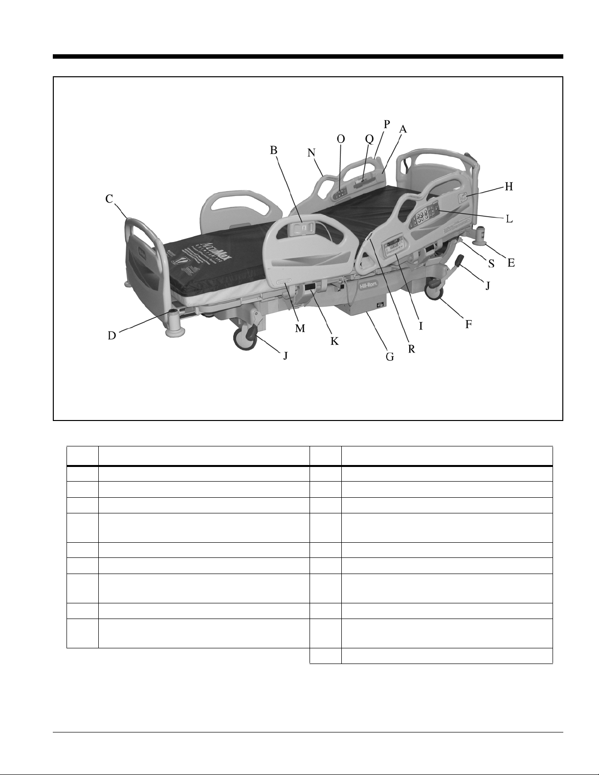
Features
Item Description Item Description
A Speaker J Brake/steer pedals
B Patient control pendant K Siderail release mechanism
C Footboard L Caregiver siderail controls
D Equipment socket M Trendelenburg/Reverse Trendelenburg
Line-of-Site® Indicator
E Wall guard N Care Grip Hand Hold
F 6" (152 mm) caster O Patient siderail controls
G 5th wheel or I
ntelliDrive® Transport
P Line Manager
System (optional)
H Line-of-Site® Head Angle Indicator Q Patient personal storage
I Scale, Bed Exit, Head of Bed alarm control
R Patient Position Indicator
pod
S IV pole storage/cord wrap
Advanta™ 2 Bed User Manual (157722 REV 2) 3
Standard Features
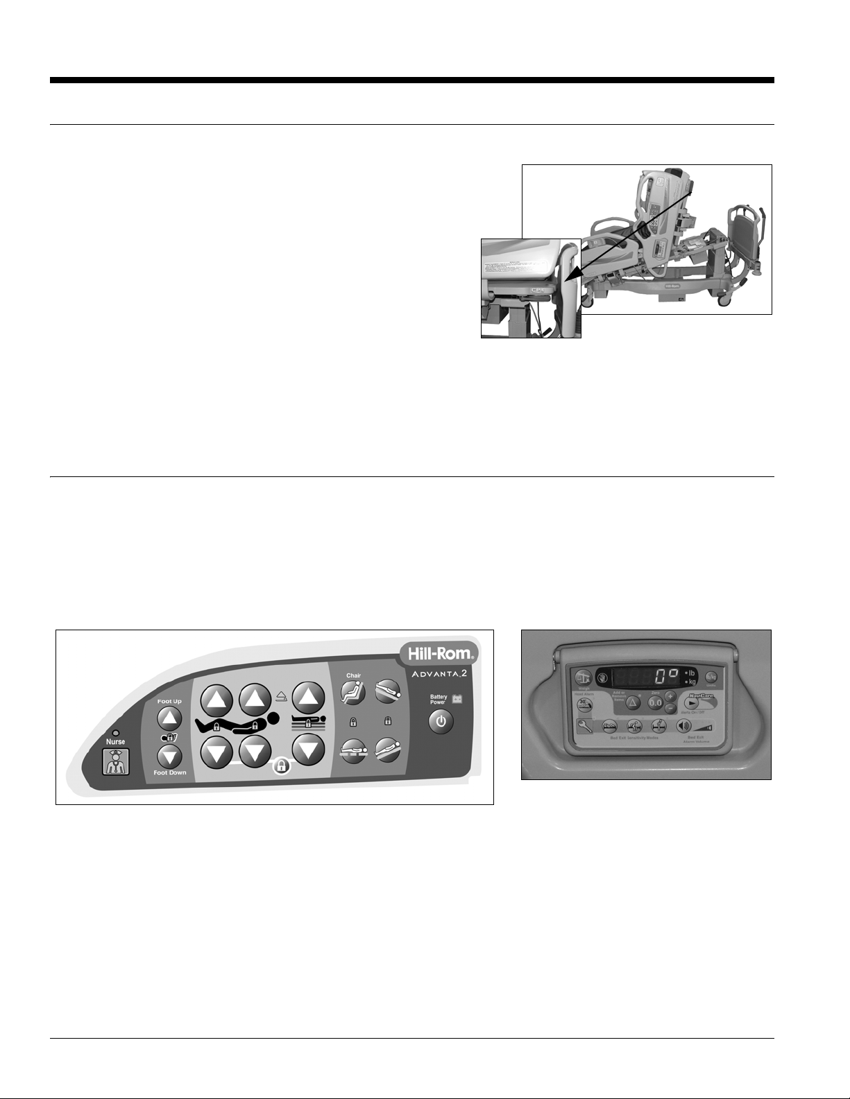
Emergency CPR Control
The Emergency CPR control handles are located at the
head end of the bed, under each corner of the sleep
deck.
When activated, the CPR release allows the head
section to lower. The CPR release function is gasassisted to cushion the movement and can be used when
power is not available.
To Activate
• Pull, and hold, the CPR control handle with one
hand.
• Let the head section come to a stop in the flat position.
• Release the CPR control handle when the head section is flat.
The head section actuator is automatically re-enabled after the CPR control handle is released.
Caregiver Siderail Controls
The caregiver siderail controls are located on the outside of the head siderails.
There are two sets of Caregiver Siderail controls. The first set is mounted on the outside of both siderails
and control the bed position functions. The second set, for the optional bed functions, is mounted on a
flip-up control pod in the head-end siderails. The second set of controls is for the scale, Head of Bed
alarm, the Bed Exit Alarm System, and NaviCare® System.
4 Advanta™ 2 Bed User Manual (157722 REV 2)
Lockout Control
NOTE:
NOTE:
The Lockout control, located on the caregiver siderail control panel, disables the bed
articulation functions.
To Activate—press and hold the Lockout control, and then press the applicable control.
Both patient and caregiver controls are locked out. An LED on the control panel comes
on when a lockout is activated.
• The Bed Up/Down lockout also locks out the Trendelenburg and Reverse Trendelenburg controls.
• The Head or Knee lockout also locks out the Chair and Bed Flat controls.
• The Knee lockout also locks out the Foot controls.
Deactivate—press and hold the Lockout control, and then press the applicable locked out control.
The Lockout control disables only articulation controls, not Nurse Call. No movement of the unit is
allowed, except for emer
gency CPR.
Bed Up/Down Control
The Bed Up/Down controls are on the head siderails.
To Raise or Lower the bed
• Press and hold the Bed Up or Bed Down control to raise or lower the bed.
• To disable the Bed Up/Down control, activate its Lockout.
When the bed is not in the low-low position, an indicator next to the Up/Down control
illuminates.
Head Up/Down Control
The Head Up/Down controls are on the head siderails. The Line-of-Site® Angle Indicators
are located on the head siderails.
To Activate—press and hold the Head Up or Head Down contr
head section.
The bed is equipped with an automatic contour feature. This function only works with the
patient controls.
ol to raise or lower the
Advanta™ 2 Bed User Manual (157722 REV 2) 5
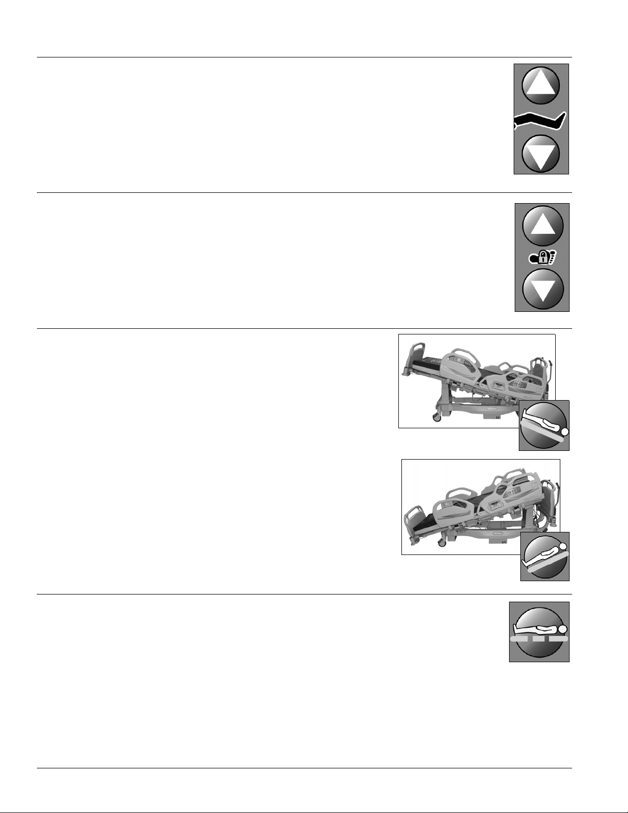
Knee Up/Down Control
Trendelenburg
Reverse
Trendelenburg
The Knee Up/Down controls are on the head siderails. The knee section has a
maximum travel of 36°.
To Activate—press and hold the Knee Up or Knee Down control to raise or lower the
knee.
The automatic contour feature does not work when using only the Knee Up/Down
controls.
Foot Up/Down Control
The Foot Up/Down controls are on the head siderails. The foot section has an inclination
of 23°.
To Activate—press and hold the Foot Up or Foot Down control to raise or lower the
foot.
If the knee section is raised, you can press the Knee Up control to keep the knee up while
you lower the foot section.
Trendelenburg and Reverse Trendelenburg Controls
The controls are on the head siderails. The Trendelenburg and
Reverse Trendelenbur g Line-of-Site® Angle Indicators are in the
foot-end siderails. The controls can be activated at any bed
height.
Trendelenburg—the foot end of the bed raises relative to the
head end.
Reverse Trendelenburg—the head end of the bed raises
relative to the foot end.
To Activate—press and hold the T
Trendelenburg control to go into the applicable position.
Deactivate—press the opposite control to return to the level
position or raise or lower the bed fully.
rendelenburg or Reverse
Bed Flat Control
The Bed Flat control is provided so that a caregiver can easily return the sleep deck to a
flat position (head and knee section down and foot section up) from any articulated
position. The Bed Flat control only returns the sleep deck to a flat position, it does not
change the angle of the bed.
To Activate—press and hold the Bed Flat control. When all sections are flat, the system stops.
6 Advanta™ 2 Bed User Manual (157722 REV 2)
Dining Chair® Position
WARNING:
WARNING:
The Dining Chair® Position control allows the caregiver to put the bed in an upright position.
The controls are located on the head siderails. When activated, the bed will articulate to a maximum of
65° for the head section, 19° for the knee section, and -12° for the foot section.
Check at regular times to make sure the patient remains correctly positioned. The use of pillows
can help maintain side-to-side positioning. Injury to the patient may result from improper
positioning.
To Activate
• Set the brake.
•Press the Dining Chair® Position control. The patient
deck moves to the chair position.
To Return to Flat Position
Press the Bed Flat control to return the sleep deck to the
flat position.
FullChair® Patient Positioning Mechanism
The FullChair® Patient Positioning Mechanism allows the
caregiver to place the patient in a fully seated position without
having to remove the patient from the bed.
Check at regular times to make sure the patient remains
correctly positioned. The use of pillows can help maintain
side-to-side positioning. Injury to the patient may result
from improper positioning.
To Activate
• Set the brake.
•Press the Dining Chair® Position control. The patient deck transitions to the chair position.
• Once the bed has finished traveling, press the Reverse Trendelenburg control until the applicable
position is reached.
To Return to Flat Position
•Press the Bed Flat control to return the sleep deck to the flat position.
•Press the Trendelenburg control to return the bed frame to the level position or fully lower the bed.
Advanta™ 2 Bed User Manual (157722 REV 2) 7
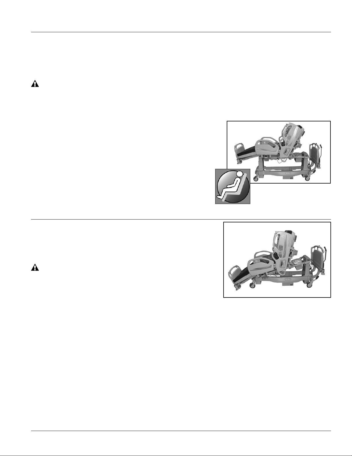
Vascular Position
NOTE:
WARNING:
WARNING:
The Vascular Position allows the caregiver
to place the patient’s legs above the level of
the patient’ s sternum without placing the bed
in the Trendelenburg position.
To Activate—press the Foot Up control.
To Return to Flat Position—press the Foot
Down control.
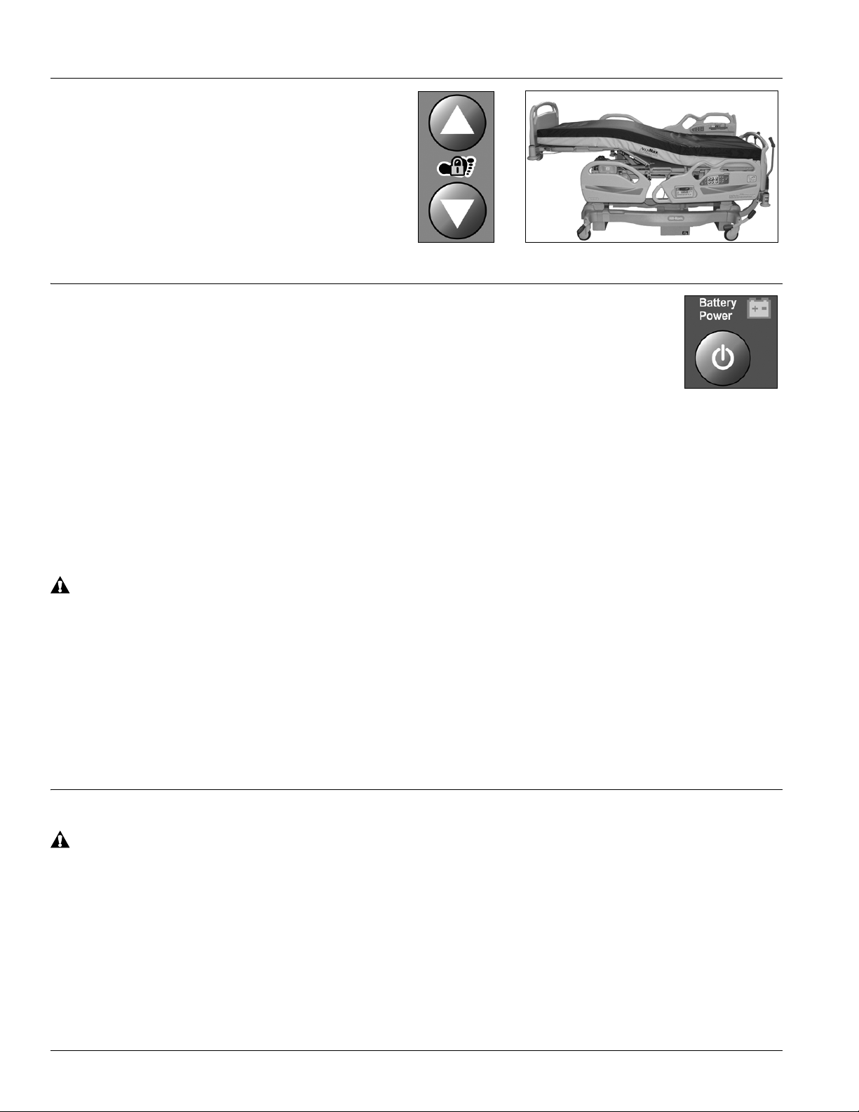
Battery Control
The battery function is available only when the bed is not connected to AC power.
To Activate—press the Battery control. The battery indicator comes on. All bed
controls are available. Battery operation is automatically stopped 30 seconds after the
end of the last movement.
When the battery charge level is low and an electrical function is activated, an alarm will sound that
indicates the battery needs to be charged. The ongoing bed movement will be completed.
Plug the bed into an applicable power source to automatically charge the battery.
If the Lockouts were not activated when AC power was removed, and the lockout LEDs are on when the
bed is connected to AC power, there is a battery problem. Contact facility maintenance to correct the
problem.
The bed must remain connected to the mains power supply until the charge LED turns on
(recharge time is approximately 10 hours for a completely discharged battery). Failure to do so
could cause the bed to not operate when power is unavailable.
If the bed is connected to AC power: the indicator flashes to indicate a low battery, and that it is charging;
if the indicator is off, the battery is fully charged.
If the bed is disconnected from AC power: the indicator is off, and the battery is not turned on; if the
indicator is on and solid, the battery is turned on; if the indicator flashes, and an alarm sounds during bed
articulation, the battery is low.
Brake and Steer Control
Unless transporting the patient, always set the brakes when the bed is occupied. Reconfirm that
the brakes are set before any patient transfer. Failure to do so may cause injury or damage.
The brake and steer controls are located on the four corners of the bed frame. There are three positions:
Brake, Neutral, and Steer . The brake position keeps the bed from mo ving. The neutral position allows the
bed to be moved sideways. The steer position allows the bed to be moved in a straight line.
When the bed is plugged into AC power and the brakes are not set, an alarm sounds until the brakes are
set or AC power is removed.
8 Advanta™ 2 Bed User Manual (157722 REV 2)
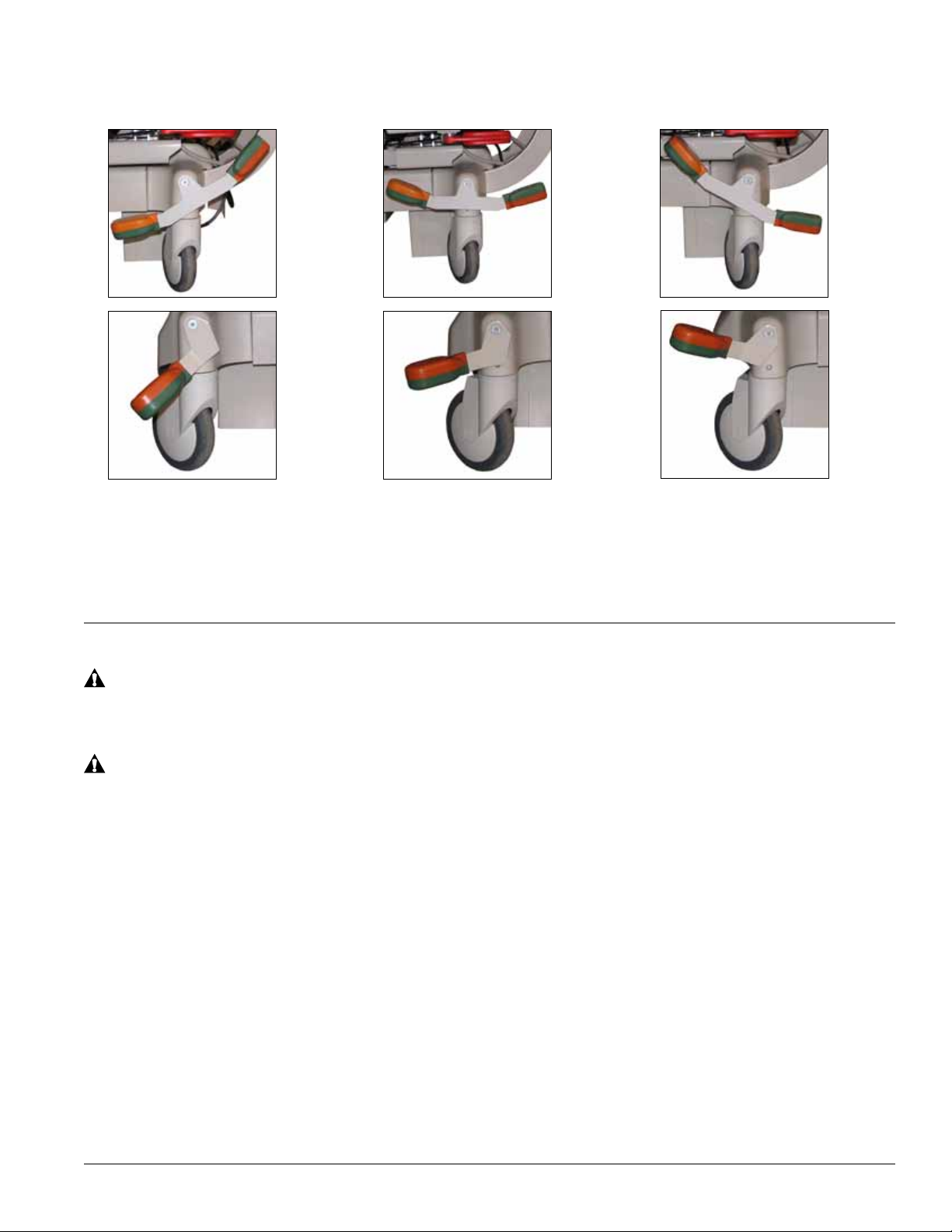
Brake
Use your foot to
step down on the
orange end of the
Neutral
Use your foot to step on the
green, or orange, end of the
Steer
Use your foot to step on the
green end of the brake/steer
brake/steer pedal
until it stops.
pedal until it stops.
travels to the middle detent.
brake/steer pedal until it
Head and Foot Siderails
WARNING:
WARNING:
NOTE:
Evaluate patients for entrapment risk according to facility protocol, and monitor patients
appropriately.
Evaluate patients for entrapment risk according to facility protocol, and monitor patients
appropriately . Make sure that all siderails are fully latched when in the raised position. Failure to
do either of these could cause serious injury or death.
Siderails are intended to be a reminder to the patient of the unit's edges, not a patient-restraining device.
When appropriate, Hill-Rom recommends that medical personnel determine the proper methods
necessary to make sure a patient remains safely in bed.
The siderails have been designed for one-step operation.
Siderails in the raised position are intended to make the patient aware of the proximity of the edge of the
sleep s
Siderails in the lowered position, below the patient surface, facilitate a patient’s entry or exit from the
bed. This design feature also facilitates unobstructed access to the patient.
urface and to assist in patient entry and exit.
Advanta™ 2 Bed User Manual (157722 REV 2) 9
To Raise
WARNING:
• Grasp the siderail by the top, not by the latch area.
• Pull the siderail up until it latches into the locked
position. A click will be heard when it latches into the
locked position.
•Once the click is heard, gently pull on the siderail to
make sure it is latched correctly
.
To Lower
• Make sure there is no weight against the siderail.
• Grasp the release handle and pull up. The siderail
lowers automatically.
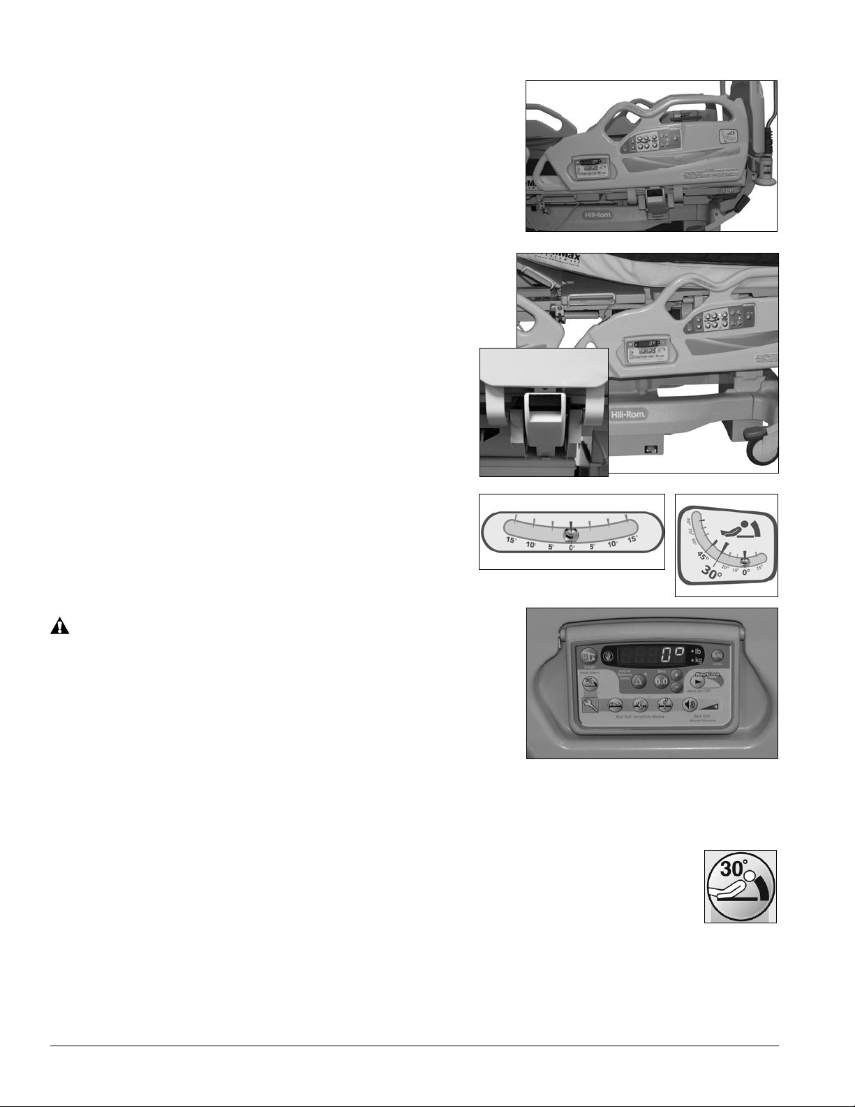
Angle Indicators
The head siderails contain the Head Angle Line-of-Site®
Angle Indicators and the foot siderails contain the
Trendelenburg Line-of-Site® Angle Indicators. The angle
is read from the center of the ball. Beds with the 30 degree
head angle alarm will also display the angle on the flip-up
control pod on the head siderails.
Failure to make sure the head section is at the correct
angle for the patient’s care could cause patient injury.
When the angle of the head section is critical to the patient’ s
care, do not depend on the head angle display only . Look to
make sure the head section is at the correct angle. If the
angle does not look correct, contact your facility-authorized
maintenance person.
On beds with the control pod and head angle display options, the display is always on and shows the head
angle of the bed unless a weight reading is being taken.
30° Head Angle Alarm
The Head Angle Alarm control is on the caregiver pod next to the display. When set, if the
head section goes below 30°, these will occur:
• The display will flash continuously.
• An audible alarm will come on.
• The alarm indicator will flash.
• If installed, the SafeView® Alerts lights will flash yellow
10 Advanta™ 2 Bed User Manual (157722 REV 2)
.
NOTE:
The display on the caregiver pod continuously shows the angle of
NOTE:
WARNING:
WARNING:
WARNING:
WARNING:
the head section. Whenever the head section goes below 30°, the
display flashes five times.
Set the Alarm
1. Raise the head section to the applicable position above 30°.
2. Press the Enable control.
3. Press the Alarm control. The alarm indicator will come on.
When the bed operates on battery power the display will be off and the alarm will not work.
Turn Off the Alarm—raise the head section above 30°.
Deactivate the Alarm
1. Press the Enable control.
2. Press the Alarm control. The alarm indicator will go off
Line Manager
Do not use the Line Manager for ventilator circuits. To do
so could cause patient injury.
When you use the Line Manager, make sure the lines are
not pinched or kinked and there is sufficient slack in the
lines for bed articulations and patient movement. Failure to
do so could cause injury or equipment damage.
Failure to keep aseptic lines separate from non-aseptic lines may cause cross contamination.
Failure to remove lines from the Line Manager before you transfer the patient could cause
patient injury or equipment damage.
A Line Manager is on each head siderail. The Line Manager helps to keep lines (such as IV fusion lines,
suction lines, oxygen lines, etc.) together and away from the articulating frame.
Observe lines closely during articulations. Always use good line management techniques, particularly as
the head section rises.
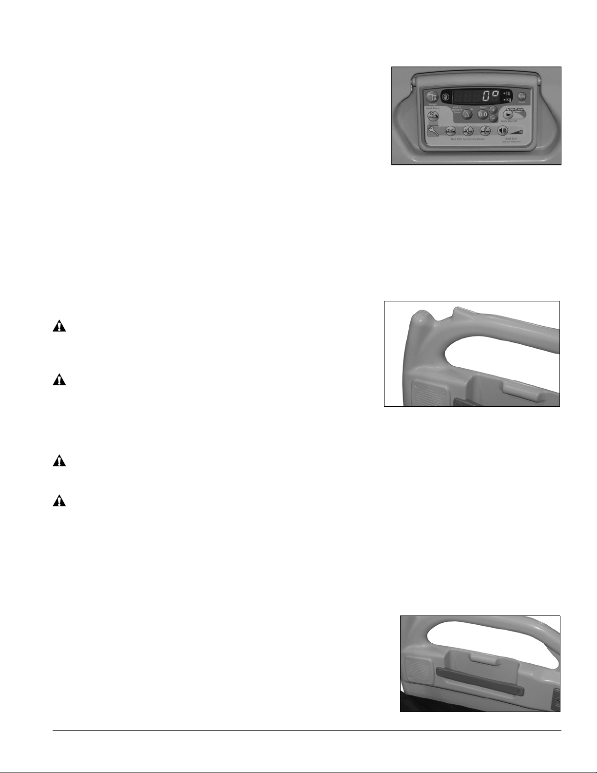
Patient Personal Storage
Each head siderail has an area in the siderail for the patient to
store items.
Advanta™ 2 Bed User Manual (157722 REV 2) 11
 Loading...