

Hill-Rom Itegris 2001B Installation Instructions Manual
DRAFT 08/27/ 03
INSTALLATION INSTRUCTIONS
Integris® 2001B
Headwall System
and Vertical Chase
(with and without a
Breaker Panel)
From Hill-Rom
Product No. P2001B
For Parts or Technical Assistance is444rc
For Parts or Technical Assistance is444re
Technical Support: (800) 445-3720
Technical Support: (800) 445-3720
Cust omer Service: (800) 445-3730
Cust omer Service: (800) 445-3730
Canada: (800) 267-2337
Canada: (800) 267-2337
International: Contact your distributor.
International: Contact your distributor.
www.hill-rom.com
www.hill-rom.com


08/27/03 DRAFT
Integris® 2001B Headwall
System and Vertical Chase
(with an d wi th out
a Breake r Pan e l)
Installation Instr uctions
Revision Letter Pages Affected Date
Original Issue May, 2000
A All August, 2000
B 1, 19, and 20 November, 2000
C All Apr il, 2001
D All October, 2001
E All October, 2003
is444re
October 13, 2003 is444re Page i

08/27/03 DRAFT
© 2003 by Hill-Rom Services, Inc. ALL RIGHTS RESERVED.
No part of this text shall be reproduced or transmitted in any form or by any
means, electronic or mechanical, including photocopying, recording, or by any
information or retrieval system without written permission from Hill-Rom
Services, Inc. (Hill-R om).
The information in this document is confidential and may not be disclosed to
third parties without the prior written consent of Hill-Rom.
Sixth Edition
First Printing 2000
Printed in the USA
E-Z Ancor® is a registered trademark of Illinois T ool Works, Inc.
Hill-Rom® is a registered trademark of Hill-Rom Services, Inc.
Integris® is a registered trademark of Hill-Ro m Servic es, Inc.
National Electrical Code® is a registered trademark of National Fire Protection
Association, Inc.
NEC® is a registered trademark of National Fire Protection Association, Inc.
The information contained in this document is subject to change without
notice. Hill-Rom makes no commitment to update or keep current, the
information contained in this manual.
The only product warranty intended by Hill-Rom is the express, written
warranty accompanying the bill of sale to the original purchaser. Hill-Rom
makes no other warranty, express or implied, and in particular, makes no
warranty of merchantability or fitnes s for a particul ar purpose.
Additional copies of this document can be obtained from Hill-Rom.
Page ii is444re October 13, 2003

DRAFT 08/27/03
Table of Contents
Introduction. . . . . . . . . . . . . . . . . . . . . . . . . . . . . . . . . . . . . . . . . . . . . . . . . . . . . . . . . . 1
Order of Ins t a l l a t i o n . . . . . . . . . . . . . . . . . . . . . . . . . . . . . . . . . . . . . . . . . . . . . . . . . . . 3
Faste n e r Id entification . . . . . . . . . . . . . . . . . . . . . . . . . . . . . . . . . . . . . . . . . . . . . . . . . 5
Determ i n ing the Wall /C o n structi o n Ty p e. . . . . . . . . . . . . . . . . . . . . . . . . . . . . . . . . . . 7
Instal l ing the Medi c al Gas Dro p s . . . . . . . . . . . . . . . . . . . . . . . . . . . . . . . . . . . . . . . . . 7
Instal l i n g th e V e r ti cal Chase w i t h a Br ea k er Panel . . . . . . . . . . . . . . . . . . . . . . . . . . . 9
Instal l ing the Han g er Bracke t . . . . . . . . . . . . . . . . . . . . . . . . . . . . . . . . . . . . . . . . . 9
Instal l i n g th e V e r ti cal Chase. . . . . . . . . . . . . . . . . . . . . . . . . . . . . . . . . . . . . . . . . 11
Installing the Vertical Chase without a Breaker Panel. . . . . . . . . . . . . . . . . . . . . . . . 13
Instal l i n g t h e Ra ceway . . . . . . . . . . . . . . . . . . . . . . . . . . . . . . . . . . . . . . . . . . . . . . . . 16
Instal l ing the Raceway Han g e r Br a c k et (s) . . . . . . . . . . . . . . . . . . . . . . . . . . . . . . 16
Positioning and Mounting a Single Raceway Section . . . . . . . . . . . . . . . . . . . . . 19
Mounting Multiple Raceway Sections . . . . . . . . . . . . . . . . . . . . . . . . . . . . . . . . . 21
Connecti n g the Gas Pipe. . . . . . . . . . . . . . . . . . . . . . . . . . . . . . . . . . . . . . . . . . . . 22
Instal l i n g t h e Co v e rs. . . . . . . . . . . . . . . . . . . . . . . . . . . . . . . . . . . . . . . . . . . . . . . . . . 23
Instal l i n g th e Ra ceway Ga s Pip e Co v e r . . . . . . . . . . . . . . . . . . . . . . . . . . . . . . . . 23
Instal l ing the Spli c e Covers . . . . . . . . . . . . . . . . . . . . . . . . . . . . . . . . . . . . . . . . . 23
Instal l i n g th e Co v e r s o n th e V e r t ical Chase with a Breake r Pan el . . . . . . . . . . . . 2 3
Installing the Covers on the Vertical Chase without a Breaker Panel . . . . . . . . . 23
October 13, 2003 is444re Page iii

Table of Contents
NOTES:
DRAFT 08/27/03
Page iv is444re October 13, 2003
DRAFT 08/27/03
Subject: Integris® 2001B Headwall System and Vertical Chase (with and
without a Breaker Panel) Installation In structions
Introduction
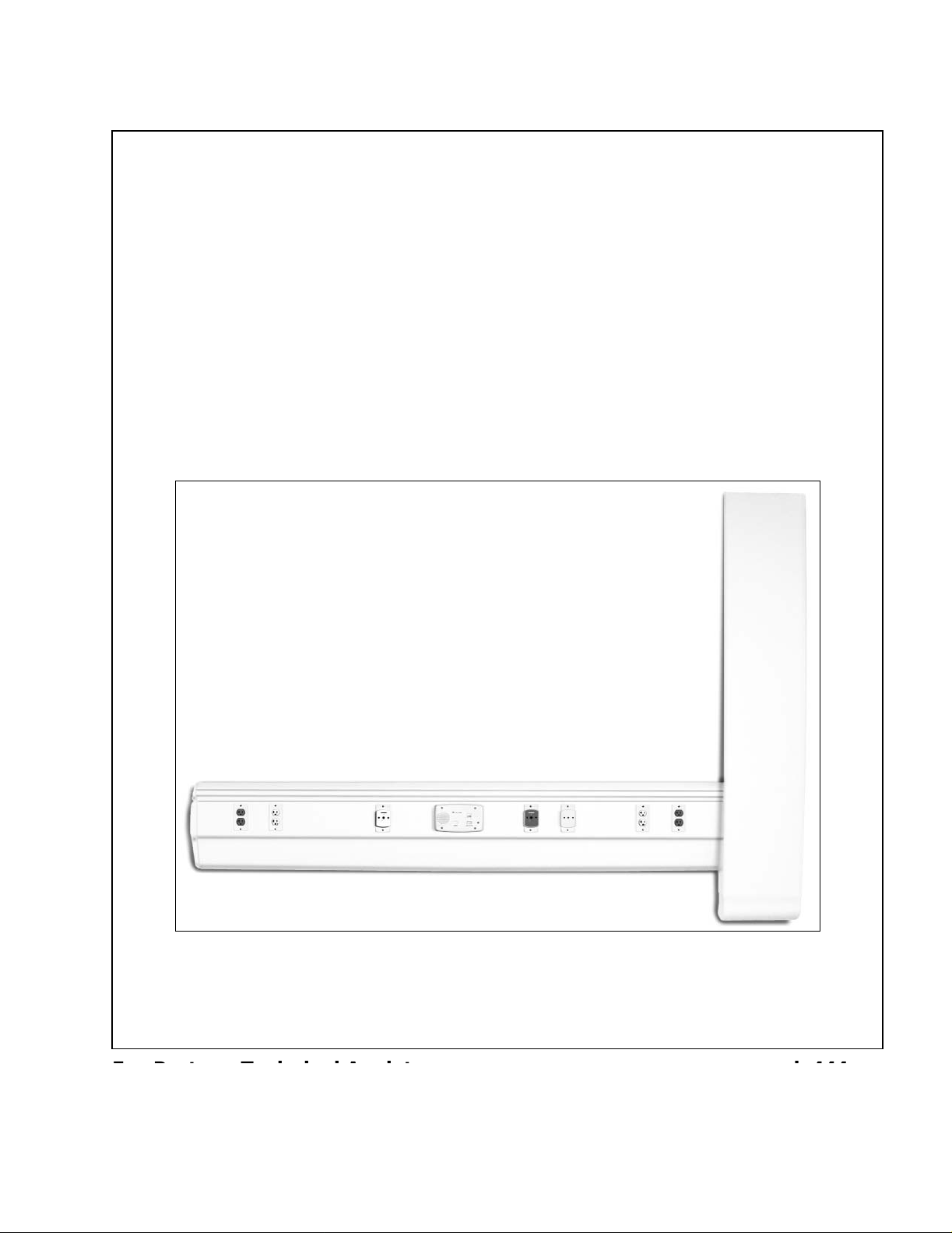
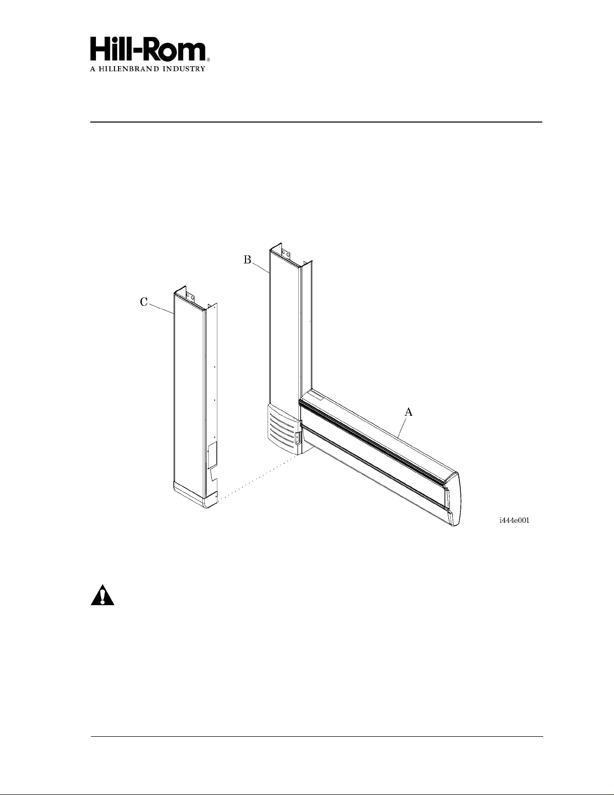
This installation instruction sheet describes how to install the Integris® 2001B Headwall
System raceway (A) and vertical chase (with a breaker panel) (B) or the vertical chase
(without a breaker panel) (C) (see figure 1 on page 1).
Figure 1. Integris® 2001B Headwall System and Vertical Chase
Prior to installation, carefully read all of the installation instructions for the components you
are installing.
WARNING:
For installation of the Integris® 2001B Headwall System (fire-rated/nonseismic), ensure that the walls are constru cted of at least 20 gauge steel studs
on 16" (41 cm) ce nter l ines , an d cove r ed with a minimum of 5/8" (15.9 mm) dry
wall. Failure to do so could result in the collapse of the Integris® 2001B
Headwall System. Personal injury or equipment damage could occur.
October 13, 2003 is444re Page 1 of 24

DRAFT 08/27/03
Before installation of the headwall system components, the facility’s medical gases and
vacuum lines should have been run to the general location according to NFPA 99 and NFPA
1
70, National Electric Code®
(NEC®2).
Tools required: Standard drill/power screwdriver
#2 phillips head screwdriver
¼" drill bit
Medium screwdriver
½" spade bit
Large screwdriver
7/8" spade bit
11/32" open end wr ench
1" spade bit
5/16" hex head nutdriver
Ratchet wrench
3/8" hex head nutdriver
9/16" deep socket with 3" extension
Tape measure
Level
Chalk line
Rubber mallet or block and hammer
Ladder
Adjustable wrench
Parts required: (1) 205935 Splice cover top, complete
(1) 205934 Splice cover lower, 2001
Related Documents: Integris® B Lite Rail Installation Instructions (is443)
1. National Elec tric Code® is a registered trademark of National Fire Protection Association, Inc.
2. NEC® is a registered trademark of National Fire Protection Association, Inc.
Page 2 of 24 is444re October 13, 2003

DRAFT 08/27/03
Order of Installation
The numbered steps below correspond with the order of installation for the lis ted components .
1. Determine the type of wall (D) and construction type (see figure 2 on page 4).
2. Install the medical gas drops (E).
3. Perform one of the following:
• T o install the vertical chase (with a breaker panel) (B), install the vertical chase
hanger bracket and the vertical chase with a breaker panel (B).
• Install the vertical chase (without a breaker panel) (C).
4. To install the raceway (A), perform the following:
a. Install the raceway hanger bracket (F).
b. Position and install a single section of raceway (A).
c. Mount multiple sections of raceway (A).
d. Connect the gas pipe.
5. To install the covers, perform the following:
a. Install the gas pipe cover (G).
b. Install the vertic al chase bottom cover (H).
October 13, 2003 is444re Page 3 of 24
 Loading...