

Hill-Rom Basic Care Bed User manual

SERVICE MANUAL
Basic Care™
Bed
From Hill-Rom
Product No. P1440/P1441
For Parts or Technical Assistance man336
USA 1-812-934-1796 Canada (800) 267-2337
International: Contact your distributor.


© 2004 by Hill-Rom Services, Inc. ALL RIGHTS RESERVED.
Manufactured for Hill-Rom by: Optima Healthcare Inc.
Distributed by:
HILL-ROM COMPANY, INC.
1069 STATE ROUTE 46 E
BATESVILLE, IN 47006-9167
No part of this text shall be reproduced or transmitted in any form or by any
means, electronic or mechanical, including photocopying, recording, or by any
information or retrieval system without written permission from Hill-Rom
Services, Inc. (Hill-Rom).
The information in this manual is confidential and may not be disclosed to
third parties without the prior written consent of Hill-Rom.
First Edition
First Printing 2004
Printed in the USA
Allen™ is a trademark of Industrial Fasteners, Inc.
Basic Care™ is a trademark of Hill-Rom Services, Inc.
CSA® is a registered trademark of Canadian Standards Association.
Hill-Rom® is a registered trademark of Hill-Rom Services, Inc.
Oilite® is a registered trademark of Beemer Precision, Incorporated.
Slo-Blo® is a registered trademark of Littelfuse, Inc.
Teflon® is a registered trademark of E.I. du Pont de Nemours and Company.
Torx® is a registered trademark of Textron, Inc.
The information contained in this manual is subject to change without notice.
Hill-Rom makes no commitment to update or keep current, the information
contained in this manual.
Basic Care™ Bed Service Manual (man336) Page i

Hill-Rom reserves the right to make changes without notice in design,
NOTE:
specifications, and models. The only warranty Hill-Rom makes is the express
written warranty extended on the sale or rental of its products.
To order additional copies of this manual (man336), refer to the back cover for
contact information. For countries not listed on the back cover, contact your
distributor.
The back cover is a comprehensive list of Technical Support contact
information for Hill-Rom. The product discussed in this manual may not be
available in all of the countries listed.
Revision Letter Pages Affected Date
Original Issue May 2004
Page ii Basic Care™ Bed Service Manual (man336)

Table of Contents
Chapter 1: Introduction
Purpose . . . . . . . . . . . . . . . . . . . . . . . . . . . . . . . . . . . . . . . . . . . . . . . . . . . . . . . . . . 1 - 1
Audience. . . . . . . . . . . . . . . . . . . . . . . . . . . . . . . . . . . . . . . . . . . . . . . . . . . . . . . . . 1 - 1
Reference Documents. . . . . . . . . . . . . . . . . . . . . . . . . . . . . . . . . . . . . . . . . . . . . . . 1 - 1
Document Symbols. . . . . . . . . . . . . . . . . . . . . . . . . . . . . . . . . . . . . . . . . . . . . . . . . 1 - 2
Specifications . . . . . . . . . . . . . . . . . . . . . . . . . . . . . . . . . . . . . . . . . . . . . . . . . . . . . 1 - 3
Physical Description . . . . . . . . . . . . . . . . . . . . . . . . . . . . . . . . . . . . . . . . . . . . . 1 - 3
Electrical Description . . . . . . . . . . . . . . . . . . . . . . . . . . . . . . . . . . . . . . . . . . . . 1 - 4
Regulations, Standards, and Codes. . . . . . . . . . . . . . . . . . . . . . . . . . . . . . . . . . 1 - 5
Model Identification . . . . . . . . . . . . . . . . . . . . . . . . . . . . . . . . . . . . . . . . . . . . . . . . 1 - 9
Safety Tips . . . . . . . . . . . . . . . . . . . . . . . . . . . . . . . . . . . . . . . . . . . . . . . . . . . . . . 1 - 10
Warning and Caution Labels . . . . . . . . . . . . . . . . . . . . . . . . . . . . . . . . . . . . . . . . 1 - 15
Chapter 2: Troubleshooting Procedures
Getting Started . . . . . . . . . . . . . . . . . . . . . . . . . . . . . . . . . . . . . . . . . . . . . . . . . . . . 2 - 1
Initial Actions . . . . . . . . . . . . . . . . . . . . . . . . . . . . . . . . . . . . . . . . . . . . . . . . . . . . . 2 - 2
Function Checks . . . . . . . . . . . . . . . . . . . . . . . . . . . . . . . . . . . . . . . . . . . . . . . . . . . 2 - 2
Final Actions. . . . . . . . . . . . . . . . . . . . . . . . . . . . . . . . . . . . . . . . . . . . . . . . . . . . . . 2 - 4
None of the Bed Functions Operate . . . . . . . . . . . . . . . . . . . . . . . . . . . . . . . . . . . . 2 - 5
The Head Up Function Does Not Operate . . . . . . . . . . . . . . . . . . . . . . . . . . . . . . . 2 - 6
The Head Down Function Does Not Operate. . . . . . . . . . . . . . . . . . . . . . . . . . . . . 2 - 8
The Head Function Does Not Operate . . . . . . . . . . . . . . . . . . . . . . . . . . . . . . . . . 2 - 10
The Knee Up Function Does Not Operate . . . . . . . . . . . . . . . . . . . . . . . . . . . . . . 2 - 11
The Knee Down Function Does Not Operate. . . . . . . . . . . . . . . . . . . . . . . . . . . . 2 - 13
The Knee Function Does Not Operate . . . . . . . . . . . . . . . . . . . . . . . . . . . . . . . . . 2 - 15
The Hilow Up Function Does Not Operate . . . . . . . . . . . . . . . . . . . . . . . . . . . . . 2 - 16
The Hilow Down Function Does Not Operate . . . . . . . . . . . . . . . . . . . . . . . . . . . 2 - 18
The Hilow Function Does Not Operate . . . . . . . . . . . . . . . . . . . . . . . . . . . . . . . . 2 - 20
Basic Care™ Bed Service Manual (man336) Page iii

Table of Contents
The Automatic Contour Up Function Does Not Operate . . . . . . . . . . . . . . . . . . . 2 - 21
The Automatic Contour Down Function Does Not Operate . . . . . . . . . . . . . . . . 2 - 22
The Trendelenburg or Reverse Trendelenburg Function Does Not Operate . . . . 2 - 23
The CPR Function Does Not Operate. . . . . . . . . . . . . . . . . . . . . . . . . . . . . . . . . . 2 - 25
Chapter 3: Theory of Operation
Introduction. . . . . . . . . . . . . . . . . . . . . . . . . . . . . . . . . . . . . . . . . . . . . . . . . . . . . . . 3 - 1
Base. . . . . . . . . . . . . . . . . . . . . . . . . . . . . . . . . . . . . . . . . . . . . . . . . . . . . . . . . . 3 - 1
Intermediate Frame. . . . . . . . . . . . . . . . . . . . . . . . . . . . . . . . . . . . . . . . . . . . . . 3 - 1
Articulating Sleep Deck . . . . . . . . . . . . . . . . . . . . . . . . . . . . . . . . . . . . . . . . . . 3 - 1
Siderails . . . . . . . . . . . . . . . . . . . . . . . . . . . . . . . . . . . . . . . . . . . . . . . . . . . . . . 3 - 1
Motion Control . . . . . . . . . . . . . . . . . . . . . . . . . . . . . . . . . . . . . . . . . . . . . . . . . 3 - 1
Transformer Configurations . . . . . . . . . . . . . . . . . . . . . . . . . . . . . . . . . . . . . . . 3 - 2
Motor Assemblies. . . . . . . . . . . . . . . . . . . . . . . . . . . . . . . . . . . . . . . . . . . . . . . 3 - 3
Battery Backup . . . . . . . . . . . . . . . . . . . . . . . . . . . . . . . . . . . . . . . . . . . . . . . . . 3 - 3
Controls. . . . . . . . . . . . . . . . . . . . . . . . . . . . . . . . . . . . . . . . . . . . . . . . . . . . . . . 3 - 3
Chapter 4: Removal, Replacement, and Adjustment Procedures
Tool and Supply Requirements. . . . . . . . . . . . . . . . . . . . . . . . . . . . . . . . . . . . . . . . 4 - 1
Control Box Assembly . . . . . . . . . . . . . . . . . . . . . . . . . . . . . . . . . . . . . . . . . . . . . . 4 - 3
Removal . . . . . . . . . . . . . . . . . . . . . . . . . . . . . . . . . . . . . . . . . . . . . . . . . . . . . . 4 - 3
Replacement . . . . . . . . . . . . . . . . . . . . . . . . . . . . . . . . . . . . . . . . . . . . . . . . . . . 4 - 4
Control Panel, Foot End . . . . . . . . . . . . . . . . . . . . . . . . . . . . . . . . . . . . . . . . . . . . . 4 - 5
Removal . . . . . . . . . . . . . . . . . . . . . . . . . . . . . . . . . . . . . . . . . . . . . . . . . . . . . . 4 - 5
Replacement . . . . . . . . . . . . . . . . . . . . . . . . . . . . . . . . . . . . . . . . . . . . . . . . . . . 4 - 6
Trendelenburg Control Box . . . . . . . . . . . . . . . . . . . . . . . . . . . . . . . . . . . . . . . . . . 4 - 7
Removal . . . . . . . . . . . . . . . . . . . . . . . . . . . . . . . . . . . . . . . . . . . . . . . . . . . . . . 4 - 7
Replacement . . . . . . . . . . . . . . . . . . . . . . . . . . . . . . . . . . . . . . . . . . . . . . . . . . . 4 - 8
Trendelenburg or Reverse Trendelenburg Assembly. . . . . . . . . . . . . . . . . . . . . . . 4 - 9
Removal . . . . . . . . . . . . . . . . . . . . . . . . . . . . . . . . . . . . . . . . . . . . . . . . . . . . . . 4 - 9
Replacement . . . . . . . . . . . . . . . . . . . . . . . . . . . . . . . . . . . . . . . . . . . . . . . . . . 4 - 11
Trendelenburg and Reverse Trendelenburg Indicators. . . . . . . . . . . . . . . . . . . . . 4 - 12
Removal . . . . . . . . . . . . . . . . . . . . . . . . . . . . . . . . . . . . . . . . . . . . . . . . . . . . . 4 - 12
Page iv Basic Care™ Bed Service Manual (man336)

Table of Contents
Replacement and Adjustment. . . . . . . . . . . . . . . . . . . . . . . . . . . . . . . . . . . . . 4 - 12
Fuses . . . . . . . . . . . . . . . . . . . . . . . . . . . . . . . . . . . . . . . . . . . . . . . . . . . . . . . . . . . 4 - 14
Removal . . . . . . . . . . . . . . . . . . . . . . . . . . . . . . . . . . . . . . . . . . . . . . . . . . . . . 4 - 14
Replacement . . . . . . . . . . . . . . . . . . . . . . . . . . . . . . . . . . . . . . . . . . . . . . . . . . 4 - 15
Battery Backup . . . . . . . . . . . . . . . . . . . . . . . . . . . . . . . . . . . . . . . . . . . . . . . . . . . 4 - 16
Removal . . . . . . . . . . . . . . . . . . . . . . . . . . . . . . . . . . . . . . . . . . . . . . . . . . . . . 4 - 16
Replacement . . . . . . . . . . . . . . . . . . . . . . . . . . . . . . . . . . . . . . . . . . . . . . . . . . 4 - 17
Head Motor. . . . . . . . . . . . . . . . . . . . . . . . . . . . . . . . . . . . . . . . . . . . . . . . . . . . . . 4 - 18
Removal . . . . . . . . . . . . . . . . . . . . . . . . . . . . . . . . . . . . . . . . . . . . . . . . . . . . . 4 - 18
Replacement . . . . . . . . . . . . . . . . . . . . . . . . . . . . . . . . . . . . . . . . . . . . . . . . . . 4 - 19
Adjustment . . . . . . . . . . . . . . . . . . . . . . . . . . . . . . . . . . . . . . . . . . . . . . . . . . . 4 - 19
CPR Cable. . . . . . . . . . . . . . . . . . . . . . . . . . . . . . . . . . . . . . . . . . . . . . . . . . . . . . . 4 - 20
Removal . . . . . . . . . . . . . . . . . . . . . . . . . . . . . . . . . . . . . . . . . . . . . . . . . . . . . 4 - 20
Replacement . . . . . . . . . . . . . . . . . . . . . . . . . . . . . . . . . . . . . . . . . . . . . . . . . . 4 - 22
Adjustment . . . . . . . . . . . . . . . . . . . . . . . . . . . . . . . . . . . . . . . . . . . . . . . . . . . 4 - 22
Knee Motor. . . . . . . . . . . . . . . . . . . . . . . . . . . . . . . . . . . . . . . . . . . . . . . . . . . . . . 4 - 23
Removal . . . . . . . . . . . . . . . . . . . . . . . . . . . . . . . . . . . . . . . . . . . . . . . . . . . . . 4 - 23
Replacement . . . . . . . . . . . . . . . . . . . . . . . . . . . . . . . . . . . . . . . . . . . . . . . . . . 4 - 24
Hilow Motor . . . . . . . . . . . . . . . . . . . . . . . . . . . . . . . . . . . . . . . . . . . . . . . . . . . . . 4 - 25
Removal . . . . . . . . . . . . . . . . . . . . . . . . . . . . . . . . . . . . . . . . . . . . . . . . . . . . . 4 - 25
Replacement . . . . . . . . . . . . . . . . . . . . . . . . . . . . . . . . . . . . . . . . . . . . . . . . . . 4 - 26
Manual Crank Handle Assembly . . . . . . . . . . . . . . . . . . . . . . . . . . . . . . . . . . . . . 4 - 27
Removal . . . . . . . . . . . . . . . . . . . . . . . . . . . . . . . . . . . . . . . . . . . . . . . . . . . . . 4 - 27
Replacement . . . . . . . . . . . . . . . . . . . . . . . . . . . . . . . . . . . . . . . . . . . . . . . . . . 4 - 28
Head or Knee Crank Rod and Drive Screw Assembly
(Manual Model Only). . . . . . . . . . . . . . . . . . . . . . . . . . . . . . . . . . . . . . . . . . . . . . 4 - 29
Removal . . . . . . . . . . . . . . . . . . . . . . . . . . . . . . . . . . . . . . . . . . . . . . . . . . . . . 4 - 29
Replacement . . . . . . . . . . . . . . . . . . . . . . . . . . . . . . . . . . . . . . . . . . . . . . . . . . 4 - 31
Hilow Crank Rod and Drive Screw Assembly Including Gas Springs
(Manual Model Only). . . . . . . . . . . . . . . . . . . . . . . . . . . . . . . . . . . . . . . . . . . . . . 4 - 32
Removal . . . . . . . . . . . . . . . . . . . . . . . . . . . . . . . . . . . . . . . . . . . . . . . . . . . . . 4 - 32
Basic Care™ Bed Service Manual (man336) Page v

Table of Contents
Replacement . . . . . . . . . . . . . . . . . . . . . . . . . . . . . . . . . . . . . . . . . . . . . . . . . . 4 - 34
CPR Handle Assembly . . . . . . . . . . . . . . . . . . . . . . . . . . . . . . . . . . . . . . . . . . . . . 4 - 35
Removal . . . . . . . . . . . . . . . . . . . . . . . . . . . . . . . . . . . . . . . . . . . . . . . . . . . . . 4 - 35
Replacement . . . . . . . . . . . . . . . . . . . . . . . . . . . . . . . . . . . . . . . . . . . . . . . . . . 4 - 36
Adjustment . . . . . . . . . . . . . . . . . . . . . . . . . . . . . . . . . . . . . . . . . . . . . . . . . . . 4 - 36
Siderails . . . . . . . . . . . . . . . . . . . . . . . . . . . . . . . . . . . . . . . . . . . . . . . . . . . . . . . . 4 - 37
Removal . . . . . . . . . . . . . . . . . . . . . . . . . . . . . . . . . . . . . . . . . . . . . . . . . . . . . 4 - 37
Replacement . . . . . . . . . . . . . . . . . . . . . . . . . . . . . . . . . . . . . . . . . . . . . . . . . . 4 - 39
Siderail Slide Bracket . . . . . . . . . . . . . . . . . . . . . . . . . . . . . . . . . . . . . . . . . . . . . . 4 - 40
Removal . . . . . . . . . . . . . . . . . . . . . . . . . . . . . . . . . . . . . . . . . . . . . . . . . . . . . 4 - 40
Replacement . . . . . . . . . . . . . . . . . . . . . . . . . . . . . . . . . . . . . . . . . . . . . . . . . . 4 - 41
Siderail Retraction Assembly . . . . . . . . . . . . . . . . . . . . . . . . . . . . . . . . . . . . . . . . 4 - 42
Removal . . . . . . . . . . . . . . . . . . . . . . . . . . . . . . . . . . . . . . . . . . . . . . . . . . . . . 4 - 42
Replacement . . . . . . . . . . . . . . . . . . . . . . . . . . . . . . . . . . . . . . . . . . . . . . . . . . 4 - 43
Siderail Control Assembly . . . . . . . . . . . . . . . . . . . . . . . . . . . . . . . . . . . . . . . . . . 4 - 44
Removal . . . . . . . . . . . . . . . . . . . . . . . . . . . . . . . . . . . . . . . . . . . . . . . . . . . . . 4 - 44
Replacement . . . . . . . . . . . . . . . . . . . . . . . . . . . . . . . . . . . . . . . . . . . . . . . . . . 4 - 45
Siderail Control Cable . . . . . . . . . . . . . . . . . . . . . . . . . . . . . . . . . . . . . . . . . . . . . 4 - 47
Removal . . . . . . . . . . . . . . . . . . . . . . . . . . . . . . . . . . . . . . . . . . . . . . . . . . . . . 4 - 47
Replacement . . . . . . . . . . . . . . . . . . . . . . . . . . . . . . . . . . . . . . . . . . . . . . . . . . 4 - 49
Siderail Top Cane . . . . . . . . . . . . . . . . . . . . . . . . . . . . . . . . . . . . . . . . . . . . . . . . . 4 - 50
Removal . . . . . . . . . . . . . . . . . . . . . . . . . . . . . . . . . . . . . . . . . . . . . . . . . . . . . 4 - 50
Replacement . . . . . . . . . . . . . . . . . . . . . . . . . . . . . . . . . . . . . . . . . . . . . . . . . . 4 - 50
Siderail Wire Cover . . . . . . . . . . . . . . . . . . . . . . . . . . . . . . . . . . . . . . . . . . . . . . . 4 - 51
Removal . . . . . . . . . . . . . . . . . . . . . . . . . . . . . . . . . . . . . . . . . . . . . . . . . . . . . 4 - 51
Replacement . . . . . . . . . . . . . . . . . . . . . . . . . . . . . . . . . . . . . . . . . . . . . . . . . . 4 - 51
Central Brake and Steer—Caster Assemblies . . . . . . . . . . . . . . . . . . . . . . . . . . . 4 - 52
Removal . . . . . . . . . . . . . . . . . . . . . . . . . . . . . . . . . . . . . . . . . . . . . . . . . . . . . 4 - 52
Replacement . . . . . . . . . . . . . . . . . . . . . . . . . . . . . . . . . . . . . . . . . . . . . . . . . . 4 - 55
Central Brake and Steer—Pedal Assemblies . . . . . . . . . . . . . . . . . . . . . . . . . . . . 4 - 57
Removal . . . . . . . . . . . . . . . . . . . . . . . . . . . . . . . . . . . . . . . . . . . . . . . . . . . . . 4 - 57
Page vi Basic Care™ Bed Service Manual (man336)

Table of Contents
Replacement . . . . . . . . . . . . . . . . . . . . . . . . . . . . . . . . . . . . . . . . . . . . . . . . . . 4 - 58
Casters for Individual Brake and Steer. . . . . . . . . . . . . . . . . . . . . . . . . . . . . . . . . 4 - 59
Removal . . . . . . . . . . . . . . . . . . . . . . . . . . . . . . . . . . . . . . . . . . . . . . . . . . . . . 4 - 59
Replacement . . . . . . . . . . . . . . . . . . . . . . . . . . . . . . . . . . . . . . . . . . . . . . . . . . 4 - 60
Bumper . . . . . . . . . . . . . . . . . . . . . . . . . . . . . . . . . . . . . . . . . . . . . . . . . . . . . . . . . 4 - 61
Removal . . . . . . . . . . . . . . . . . . . . . . . . . . . . . . . . . . . . . . . . . . . . . . . . . . . . . 4 - 61
Replacement . . . . . . . . . . . . . . . . . . . . . . . . . . . . . . . . . . . . . . . . . . . . . . . . . . 4 - 61
Sleep Surface Panels. . . . . . . . . . . . . . . . . . . . . . . . . . . . . . . . . . . . . . . . . . . . . . . 4 - 62
Removal . . . . . . . . . . . . . . . . . . . . . . . . . . . . . . . . . . . . . . . . . . . . . . . . . . . . . 4 - 62
Replacement . . . . . . . . . . . . . . . . . . . . . . . . . . . . . . . . . . . . . . . . . . . . . . . . . . 4 - 63
Chapter 5: Parts List
Service Parts Ordering . . . . . . . . . . . . . . . . . . . . . . . . . . . . . . . . . . . . . . . . . . . . . . 5 - 1
Exchange Policy . . . . . . . . . . . . . . . . . . . . . . . . . . . . . . . . . . . . . . . . . . . . . . . . . . . 5 - 3
In-Warranty Exchanges . . . . . . . . . . . . . . . . . . . . . . . . . . . . . . . . . . . . . . . . . . 5 - 3
Out-of-Warranty Exchanges. . . . . . . . . . . . . . . . . . . . . . . . . . . . . . . . . . . . . . . 5 - 3
Warranty . . . . . . . . . . . . . . . . . . . . . . . . . . . . . . . . . . . . . . . . . . . . . . . . . . . . . . . . . 5 - 5
Recommended Spare Parts . . . . . . . . . . . . . . . . . . . . . . . . . . . . . . . . . . . . . . . . . . . 5 - 6
Base Frame . . . . . . . . . . . . . . . . . . . . . . . . . . . . . . . . . . . . . . . . . . . . . . . . . . . . . . . 5 - 8
Upper Frame for the Electric Model Basic Care™ Bed. . . . . . . . . . . . . . . . . . . . 5 - 10
Upper Frame for the Manual Model Basic Care™ Bed . . . . . . . . . . . . . . . . . . . . 5 - 12
Siderails . . . . . . . . . . . . . . . . . . . . . . . . . . . . . . . . . . . . . . . . . . . . . . . . . . . . . . . . 5 - 14
Power Cord . . . . . . . . . . . . . . . . . . . . . . . . . . . . . . . . . . . . . . . . . . . . . . . . . . . . . . 5 - 16
Sleep Surface . . . . . . . . . . . . . . . . . . . . . . . . . . . . . . . . . . . . . . . . . . . . . . . . . . . . 5 - 18
Chapter 6: General Procedures
Cleaning and Care. . . . . . . . . . . . . . . . . . . . . . . . . . . . . . . . . . . . . . . . . . . . . . . . . . 6 - 1
General Cleaning . . . . . . . . . . . . . . . . . . . . . . . . . . . . . . . . . . . . . . . . . . . . . . . 6 - 1
Steam Cleaning. . . . . . . . . . . . . . . . . . . . . . . . . . . . . . . . . . . . . . . . . . . . . . . . . 6 - 2
Hard to Clean Spots . . . . . . . . . . . . . . . . . . . . . . . . . . . . . . . . . . . . . . . . . . . . . 6 - 2
Disinfecting. . . . . . . . . . . . . . . . . . . . . . . . . . . . . . . . . . . . . . . . . . . . . . . . . . . . 6 - 2
Component Handling . . . . . . . . . . . . . . . . . . . . . . . . . . . . . . . . . . . . . . . . . . . . . . . 6 - 2
P.C. Board. . . . . . . . . . . . . . . . . . . . . . . . . . . . . . . . . . . . . . . . . . . . . . . . . . . . . 6 - 2
Basic Care™ Bed Service Manual (man336) Page vii

Table of Contents
Lubrication Requirements. . . . . . . . . . . . . . . . . . . . . . . . . . . . . . . . . . . . . . . . . . . . 6 - 3
Preventive Maintenance . . . . . . . . . . . . . . . . . . . . . . . . . . . . . . . . . . . . . . . . . . . . . 6 - 5
Preventive Maintenance Schedule . . . . . . . . . . . . . . . . . . . . . . . . . . . . . . . . . . 6 - 6
Preventive Maintenance Checklist . . . . . . . . . . . . . . . . . . . . . . . . . . . . . . . . . . 6 - 7
Basic Care™ Bed—Sleep Mode . . . . . . . . . . . . . . . . . . . . . . . . . . . . . . . . . . . . . . 6 - 8
CPR Cable Adjustment. . . . . . . . . . . . . . . . . . . . . . . . . . . . . . . . . . . . . . . . . . . . . 6 - 10
Chapter 7: Accessories
Basic Care™ Bed Accessories . . . . . . . . . . . . . . . . . . . . . . . . . . . . . . . . . . . . . . . . 7 - 1
IV Pole—P1445 . . . . . . . . . . . . . . . . . . . . . . . . . . . . . . . . . . . . . . . . . . . . . . . . . . . 7 - 2
Installation . . . . . . . . . . . . . . . . . . . . . . . . . . . . . . . . . . . . . . . . . . . . . . . . . . . . 7 - 2
Removal . . . . . . . . . . . . . . . . . . . . . . . . . . . . . . . . . . . . . . . . . . . . . . . . . . . . . . 7 - 2
Adjustment . . . . . . . . . . . . . . . . . . . . . . . . . . . . . . . . . . . . . . . . . . . . . . . . . . . . 7 - 3
Trapeze Support—P846D48. . . . . . . . . . . . . . . . . . . . . . . . . . . . . . . . . . . . . . . . . . 7 - 4
Installation . . . . . . . . . . . . . . . . . . . . . . . . . . . . . . . . . . . . . . . . . . . . . . . . . . . . 7 - 4
Removal . . . . . . . . . . . . . . . . . . . . . . . . . . . . . . . . . . . . . . . . . . . . . . . . . . . . . . 7 - 5
Fracture Frame Adapter—P847B and P847C . . . . . . . . . . . . . . . . . . . . . . . . . . . . 7 - 6
Installation . . . . . . . . . . . . . . . . . . . . . . . . . . . . . . . . . . . . . . . . . . . . . . . . . . . . 7 - 6
Removal . . . . . . . . . . . . . . . . . . . . . . . . . . . . . . . . . . . . . . . . . . . . . . . . . . . . . . 7 - 6
Page viii Basic Care™ Bed Service Manual (man336)

Purpose
Audience
1
Chapter 1
Introduction
This manual contains instructions for the operation and maintenance of the
Basic Care™ Bed. It also includes parts lists (in chapter 5) for ordering
replacement components.
This manual is intended for use by only facility-authorized personnel. Ignoring
this restriction can result in severe injury to people and serious damage to
equipment.
Reference Documents
For more information (such as operating instructions, features, and product
symbols), refer to the Basic Care™ Bed User Manual (usr124).
Basic Care™ Bed Service Manual (man336) Page 1 - 1
Document Symbols
Chapter 1: Introduction
Document Symbols
This manual contains different typefaces and symbols designed to improve
readability and increase understanding of its content:
• Standard text—used for regular data.
• Boldface text—emphasizes a word or phrase.
• NOTE:—sets apart special data or important instruction clarification.
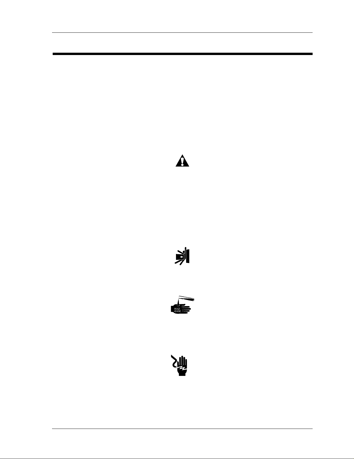
• The symbol below shows a WARNING or CAUTION:
– A WARNING identifies situations or actions that could affect
Figure 1-1. Warning and Caution
patient or user safety. Disobeying a warning could result in
patient or user injury.
– A CAUTION points out special procedures or precautions that
personnel must obey to avoid equipment damage.
• The symbol below identifies a CAUGHT HAZARD WARNING:
Figure 1-2. Caught Hazard Warning
• The symbol below identifies a CHEMICAL HAZARD WARNING:
Figure 1-3. Chemical Hazard Warning
• The symbol below identifies an ELECTRICAL SHOCK HAZARD
WARNING:
Figure 1-4. Electrical Shock Hazard Warning
Page 1 - 2 Basic Care™ Bed Service Manual (man336)

Specifications
Physical Description
Table 1-1. Physical Description
Feature Dimension
Head section slope (maximum) 72.5° ±1°
Knee section slope (maximum) 25° ±1°
Sleep deck height range 18.3" to 30.1" ± 1"
(46.5 cm to 76.5 cm ± 2.5 cm)
Trendelenburg position (maximum) 12° (+2°, -0°)
Specifications
Chapter 1: Introduction
1
Reverse Trendelenburg position
(maximum)
Bed lift capacity (maximum safe working
load)
Foot section lift capacity (maximum) 200 lb (91 kg)
Head section lift capacity (maximum) 200 lb (91 kg)
Maximum height of seat section (in Tren-
delenburg position)
Siderail opening size 3.875" (9.843 cm)
Distance between siderails 11.375" (28.893 cm)
Length—with standard sleep deck 89" to 91"
Length—with short sleep deck 86" to 88" (218 cm to 224 cm)
Sleep deck length—standard model 79" to 81" (201 cm to 206 cm)
Sleep deck length—short model 76" to 78" (193 cm to 198 cm)
Maximum width—with siderails raised 43.7" ± 0.8" (110.9 cm ± 2.0 cm)
Minimum width—with siderail stored 36.6" ± 0.8" (93.0 cm ± 2.0 cm)
12° (+2°, -0°)
450 lb (204 kg)
23.5" (59.7 cm)
(226 cm to 231 cm)
Sleep deck width 36.25" ± 0.5 (92.08 cm ± 1.3 cm)
Maximum headboard height 44" (112 cm)
Minimum underbed clearance 5.5" (13.9 cm)
Wheel base 61" (155 cm)
Caster size 5" (13 cm)
Total weight 310 lb (141 kg)
Basic Care™ Bed Service Manual (man336) Page 1 - 3

Specifications
Chapter 1: Introduction
Table 1-2. Recommended Mattress Dimensions
Feature Dimension
Mattress width 36" to 37" (91 cm to 94 cm)
Mattress length—standard model 80" to 81" (203 cm to 206 cm)
Mattress length—short model 76" to 77" (193 cm to 196 cm)
Mattress thickness 6" to 7" (15 cm to 18 cm)
Table 1-3. Environmental Conditions for Transport and Storage
Condition Range
Temperature -40°F to 158°F (-40°C to 70°C)
Relative humidity (RH) 10% to 95%
Atmospheric pressure 500 hPa to 1060 hPa
Table 1-4. Environmental Conditions for Use
Condition Range
Temperature 50°F to 104°F (10°C to 40°C) ambient tempera-
ture
Relative humidity (RH) 30% to 95%, non-condensing
Atmospheric pressure 700 hPa to 1060 hPa
Electrical Description
Table 1-5. Electrical Description
Condition Range
Rated voltage 100 V AC
110 V AC to 115 V AC
120 V AC to 127 V AC
220 V AC to 230 V AC
240 V AC
Power/Input 100 V AC to 127 V AC—1.0 A
220 V AC to 240 V AC—0.5 A
Frequency 50/60 Hz
Page 1 - 4 Basic Care™ Bed Service Manual (man336)

Table 1-6. Battery Specifications
Condition Range
Specifications
Chapter 1: Introduction
1
Maximum battery life, with no functions
operated and with the bed disconnected
from its power source
Time necessary to recharge a fully discharged battery
Battery fuse 15A
Maximum hilow cycles with fully charged battery:
With 0 lb (0 kg) on bed 21
With 250 lb (113 kg) on bed 15
With 450 lb (204 kg) on bed 11
24 hours
8 hours
Regulations, Standards, and Codes
Table 1-7. Regulations, Standards, and Codes
Classification Standard
Technical and Quality Assurance Standards
UL 60601-1
CSA®a C22.2 No. 601.1
EN 60601-2-38, including amendment 1
EN 60601-1
IEC 60601-1-2
EN ISO 9002
Equipment classification per EN
60601-1
Degree of protection against
electric shock
Classification according to
Directive 93/42/EEC
Degree of protection against the
presence of flammable anaesthetic mixtures
IPX classification IPX 4—According to IEC 60529, rating for protection
a. CSA® is a registered trademark of Canadian Standards Association, Inc.
Basic Care™ Bed Service Manual (man336) Page 1 - 5
Class I equipment, internally powered equipment
Type B
Class I
Not for use with flammable anaesthetics.
against fluid ingress and identified as equipment that is
protected against unpressurized spraying and splashing
water.

Specifications
Chapter 1: Introduction
Table 1-8. Guidance and Manufacturer’s Declaration—Electromagnetic
Emissions
The Basic Care™ Bed is intended for use in the electromagnetic environment specified
below. The customer or the user of the bed should make sure that it is used in such an environment.
Emissions Test Compliance Electromagnetic Environment—Guidance
RF Emissions
CISPR 11
Group 1 The Basic Care™ Bed uses RF energy only for its
internal functions. Therefore, its RF emissions are
low and are not likely to cause any interference in
nearby electronic equipment.
RF Emissions
CISPR 11
Class A The Basic Care™ Bed is suitable for use in all
establishments other than domestic and those
directly connected to the public low-voltage
Harmonic
Emissions
IEC 61000-3-2
Voltage
Fluctuations/
Not
applicable
Not
applicable
power supply network that supplies buildings used
for domestic purposes.
Flicker Emissions
IEC 61000-3-3
Table 1-9. Guidance and Manufacturer’s Declaration—Electromagnetic
Immunity
The Basic Care™ Bed is intended for use in the electromagnetic environment specified
below. The customer or the user of the bed should make sure that it is used in such an environment.
Immunity Test
Electrostatic
Discharge
(ESD)
IEC 61000-4-2
IEC 60601
Test Level
± 6 kV Contact
± 8 kV Air
Compliance Level
± 6 kV Contact
± 8 kV Air
Electromagnetic
Environment—Guidance
Floors should be wood,
concrete, or ceramic tile.
If floors are covered with
synthetic material, the
relative humidity should
be at least 30%.
Page 1 - 6 Basic Care™ Bed Service Manual (man336)

Specifications
Chapter 1: Introduction
1
Immunity Test
Radiated RF
IEC 61000-4-3
Electrical Fast
Transient/Burst
IEC 61000-4-4
Surge
IEC 61000-4-5
Conducted RF
IEC 61000-4-6
IEC 60601
Test Level
3 Vrms
80 MHz to 2.5 GHz
± 2 kV on Power
Supply Lines
± 1 kV on Input/
Output Lines
± 1 kV Differential
Mode
± 2 kV Common
Mode
3 Vrms
150 kHz to 80 MHz
10 Vrms from 80
MHz to 2.5 GHz
Compliance Level
3 Vrms
80 MHz to 2.5 GHz
± 2 kV on Power
Supply Lines
± 1 kV on Input/
Output Lines
± 1 kV Differential
Mode
± 2 kV Common
Mode
3 Vrms
150 kHz to 80 MHz
10 Vrms from 80
MHz to 2.5 GHz
Electromagnetic
Environment—Guidance
Portable and mobile RF
communications equipment should not be used
at close distances to the
Basic Care™ Bed. (See
Note 2.)
Mains power quality
should be that of a typical commercial or hospital environment.
Mains power quality
should be that of a typical commercial or hospital environment.
Portable and mobile RF
communications equipment (cell phones)
should not be used at
close distances to the
Basic Care™ Bed. (See
Note 2.)
Power Frequency Magnetic Fields
IEC 61000-4-8
Basic Care™ Bed Service Manual (man336) Page 1 - 7
3 A/m 3 A/m Power frequency mag-
netic fields should be at
levels characteristic of a
typical location in a typical commercial or hospital environment.

Specifications
Chapter 1: Introduction
Immunity Test
Voltage Dips,
Short Interrupts, & Variations On Power
Supply Lines
IEC 61000-411
IEC 60601
Test Level
< 5% UT
(95% dip in UT for
0.5 cycles)
< 40% U
(60% dip in U
T
for
T
5 cycles)
< 70% UT
(30% dip in UT for
25 cycles)
< 5% UT
(95% dip in UT for
5 seconds)
Compliance Level
< 5% UT
(95% dip in UT for
0.5 cycles)
< 40% U
(60% dip in U
T
for
T
5 cycles)
< 70% UT
(30% dip in UT for
25 cycles)
< 5% UT
(95% dip in UT for
5 seconds)
Electromagnetic
Environment—Guidance
Mains power quality
should be that of a typical commercial or hospital environment. If
operation is necessary
during an extended
power outage or interruption, the Basic
Care™ Bed should be
switched to operate from
the backup battery.
(See note 1.)
Note 1: UT is the AC mains voltage prior to application of the test level.
Note 2: The compliance levels in the ISM frequency range 150 kHz to 2.5 GHz are
intended to decrease the likelihood that mobile/portable communications equipment could
cause interference if it is inadvertently brought into the patient area. However, Emission
limits, IEC 60601 Test Levels, and tests specified in IEC 60601-1-2:2001 do not address
Electromagnetic Compatibility of electrical equipment at very close distances. Care should
always be exercised when using any electrical or RF equipment in the immediate patient
area.
Page 1 - 8 Basic Care™ Bed Service Manual (man336)

Model Identification
Model Number Description
P1440 Basic Care™ Bed—electric model
P1441 Basic Care™ Bed—manual model
Model Identification
Chapter 1: Introduction
1
Table 1-10. Model Identification
Basic Care™ Bed Service Manual (man336) Page 1 - 9

Safety Tips
NOTE:
Chapter 1: Introduction
Safety Tips
To help prevent the risk of hospital bed fires, make sure facility personnel
follow the safety tips in the FDA Public Health Notification: Safety Tips for
Preventing Hospital Bed Fires.
WARNING:
Evaluate patients for entrapment risk according to facility protocol, and
monitor patients appropriately.
WARNING:
Evaluate patients for entrapment risk according to facility protocol, and
monitor patients app r opr iately. Ensure that all siderails ar e f ul ly latched
when in the raised position. Failure to do either of these could result in
serious injury or death.
Siderails are intended to be a reminder to the patient of the unit's edges, not a
patient-restraining device.When appropriate, Hill-Rom recommends that
medical personnel determine the proper methods necessary to ensure a patient
remains safely in bed.
WARNING:
Make sure the be d is in the lo w positi on whe n the pa tient is unattend ed.
This may reduce the severity of any resultant injuries from patient falls.
WARNING:
Always set the brakes when the unit is occupied, except during patient
transport. Reconfirm before any patient transfer. Failure to do so may
result in personal injury or equipment damage.
WARNING:
Deactivate the bed fu nctions by using the lo ckou t co ntr ol. Mo vem en t o f
a patient or inadvertent activation of the bed functions by untrained
individuals could result in persona l injury.
Page 1 - 10 Basic Care™ Bed Service Manual (man336)

Safety Tips
Chapter 1: Introduction
WARNING:
Do not work under an unsupported load. Install appropriate temporary
supports. Failure to do so could result in personal injury or equipment
damage.
WARNING:
Put caster blocks behind the casters at the opposite end of the bed.
Failure to do so could result in personal injury.
WARNING:
Only facility-authorized personnel should service the Ba sic Care™ Bed.
Servicing by unauthorized personnel could result in personal injury or
equipment damage.
1
WARNING:
Obey the product manufactur er’ s instru cti ons. Failure to do so could
result in personal injury or equipment damage.
WARNING:
Attach the foot section to the h ead section. Failure to do so could result
in personal injury.
WARNING:
Powered bed mechanisms can cause serious injury. Operate the bed
only with persons clear of mechanisms.
WARNING:
Remove the pati ent from the bed befor e doing this procedur e. Failu re to
do so could result in personal injury or equipment not operating
correctly.
WARNING:
Wear eye protection. Failure to do so may result in eye injury.
Basic Care™ Bed Service Manual (man336) Page 1 - 11

Safety Tips
Chapter 1: Introduction
WARNING:
Improper use or handl ing of the pow er cord may result in d amage to the
power cord. If damage has occurred to the power cord or any of its
components, imme diately remove the unit from service, and co ntact the
appropriate main tenance personnel. Failure to do so could result in
electrical shock or other personal injury or equipment damage.
WARNING:
Fluid spills onto the bed electronics can result in a hazard. If such a spill
occurs, unplug the bed, and remove it from service. Failure to do so
could result in personal injury or equipment damage.
WARNING:
Adhere to approp riat e inf ection con trol poli cies an d pro ced ures. Fai lure
to do so could result in the spread of infection.
WARNING:
Failure to install the IV pole correctly could allow it to fall, resulting in
personal injury or equipment damage.
SHOCK HAZARD:
Disconnect the bed from its power source. Failure to do so could result
in personal injury or equipment damage.
SHOCK HAZARD:
Do not expose the unit to excessive moisture. Pers onal injury or
equipment damage could occur.
SHOCK HAZARD:
The potential for electrical shock exists with electrical equipment.
Failure to follow facility protocols may result in death or serious
personal injury.
CAUTION:
Make sure that a flat side of the hex rod is facing upward when it is
installed. Failure to do so may result in the central brake and steer not
operating correctly.
Page 1 - 12 Basic Care™ Bed Service Manual (man336)

Safety Tips
Chapter 1: Introduction
CAUTION:
Use care when removing indicator caps . Failure to do so coul d damage
the indicator cap.
CAUTION:
Use caution when cutting wire ties. Failure to do so could result in cable
damage.
CAUTION:
Keep enough slack in the cables to allow the bed to move through its
full range of mo tion w ithout pu tting fo rce on any of the cables . Failu re to
do so could result in equipment damage.
CAUTION:
Do not use harsh cleansers/disinfectants such as scouring pads, heavy
duty grease removers, solvents such as toluene, xylene, or acetone.
Equipment damage could occur.
1
CAUTION:
Do not use silicone-based lubricants. Equipment damage could occur.
CAUTION:
Put the removed P.C. boards in antistatic protective bags for shipping
and storage. Equipment damage can occur.
CAUTION:
Make sure that your hands are clean, and only handle the P.C. boards
by their edges to prevent component damage.
CAUTION:
Wear an antistatic strap when handling electroni c compo ne nts. Failur e
to do so could result in component damage.
Basic Care™ Bed Service Manual (man336) Page 1 - 13

Safety Tips
Chapter 1: Introduction
CAUTION:
Before transporting the unit, ensure that the power cord, hoses, and
other equipment are properly stowed. Failure to do so could result in
equipment damage.
CAUTION:
Do not push or pull the unit by IV poles, siderails, or other equipment.
Use the transp ort handles, footboard, or other designat ed location.
Failure to do so can result in equipment damage.
CAUTION:
Do not lower the bed frame while the trapeze support assembly is
attached to the be d. Turn off the hilow fu nctio n u sing th e lockout on the
foot end control panel. Otherwise, equipment damage could occur.
CAUTION:
Connect the cables to the correct socket. Failure to do so may cause
the equipment to operate incorrectly.
CAUTION:
Dispose of batteries according to your local regulations. Failure to
dispose of batteries correctly may damage the environment.
Page 1 - 14 Basic Care™ Bed Service Manual (man336)
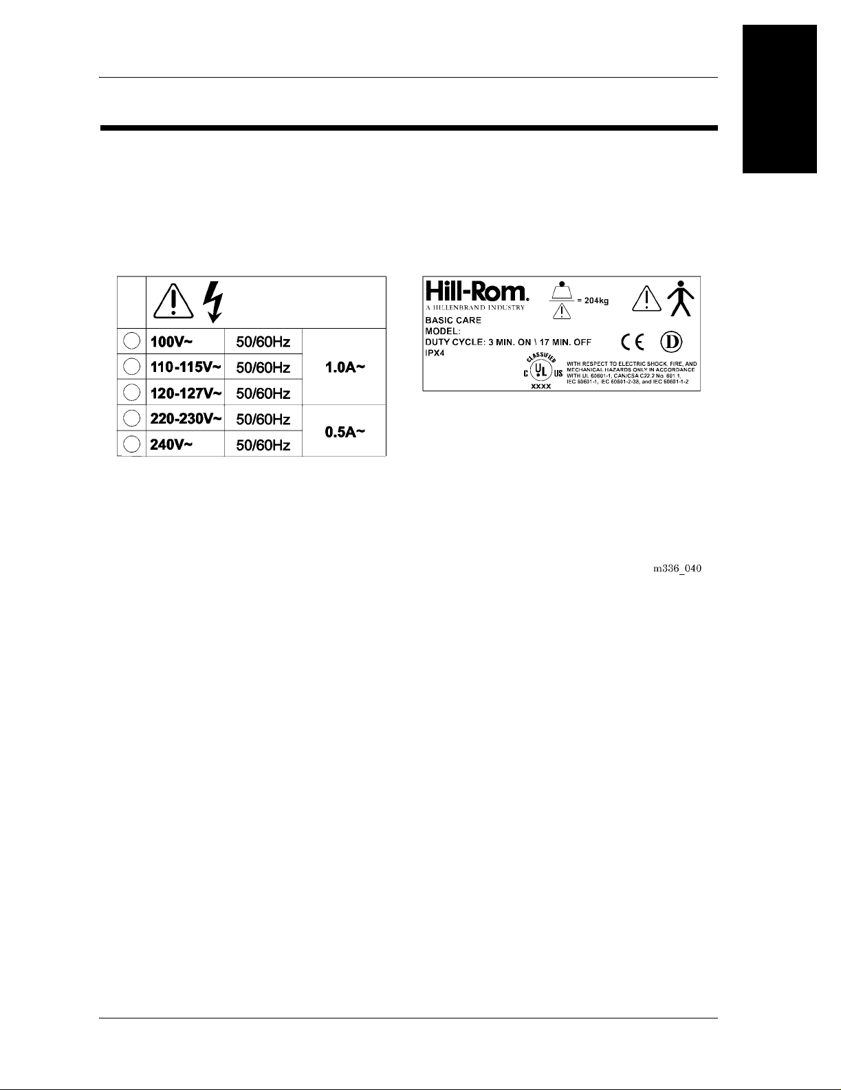
Warning and Caution Labels
Figure 1-5. Warning and Caution Labels
Warning and Caution Labels
Chapter 1: Introduction
1
Basic Care™ Bed Service Manual (man336) Page 1 - 15
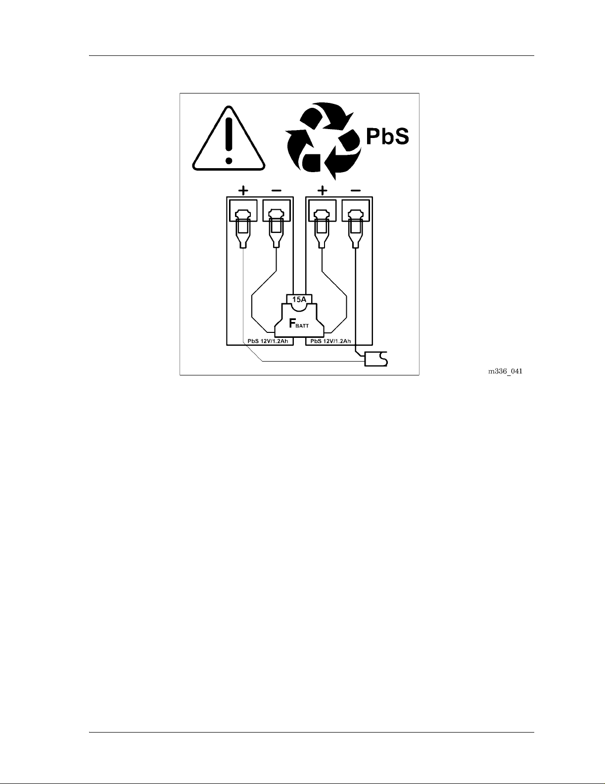
Warning and Caution Labels
Chapter 1: Introduction
Figure 1-6. Battery Backup Wiring Diagram
Page 1 - 16 Basic Care™ Bed Service Manual (man336)

Troubleshooting Procedures
Getting Started
WARNING:
Only facility-authorized personnel should service the Ba sic Care™ Bed.
Servicing by unauthorized personnel could result in personal injury or
equipment damage.
Begin each procedure in this chapter with step 1. Follow the sequen ce outlined
(each step assumes the previous step has been completed). In each step, the
normal operation of the product can be made by answering Yes or No to the
statement. Your response will lead to another step in the procedure, a repair
analysis procedure (RAP), or a component replacement. If more than one
component is listed, replace them in the order given.
Chapter 2
2
To begin gathering data about the problem, start with Initial Actions.
Do the Function Checks to isolate or identify a problem and to make sure the
repair (replacing or adjusting a part, seating a connector, etc.) corrected the
problem.
Do the Final Actions after the Function Checks to make sure the repair
corrected the problem.
If troubleshooting procedures do not isolate the problem, call Hill-Rom
Technical Support at 1-812-934-1796.
Basic Care™ Bed Service Manual (man336) Page 2 - 1

Initial Actions
Chapter 2: Troubleshooting Procedures
Initial Actions
Use Initial Actions to gather data from operators about problems with the
Basic Care™ Bed. Note symptoms or other data about the problem that the
operator describes. This data helps identify the most possible cause.
1. Someone who can explain the problem is available.
Yes No
↓→Go to “Function Checks” on page 2-2.
2. Ask that person to demonstrate or explain the problem. The problem can be
demonstrated.
Yes No
↓→Go to “Function Checks” on page 2-2.
3. The problem is a result of incorrect operator action.
Yes No
↓→Go to “Function Checks” on page 2-2.
4. Instruct the operator to refer to the Basic Care™ Bed User Manual
(usr124). To make sure the Basic Care™ Bed is operating correctly, do the
“Function Checks” on page 2-2.
Function Checks
1. Initial Actions have been done.
Yes No
↓→Go to “Initial Actions” on page 2-2.
2. The bed is connected to the correct power source.
Yes No
↓→Connect the bed to the correct power source. If this corrects the
3. Test all of the bed functions for up and down operation. All of the up and
down bed functions operate correctly.
Yes No
↓→Make sure the lockouts for all of the bed functions are not locked
problem, go to “Final Actions” on page 2-4. Otherwise, go to
step 3.
out. If this corrects the problem, go to “Final Actions” on page
2-4. Otherwise, go to step 4.
Page 2 - 2 Basic Care™ Bed Service Manual (man336)

Chapter 2: Troubleshooting Procedu res
4. Press the Head Up switch. The head section rises.
Yes No
↓→Go to page 2-6.
5. Press the Head Down switch. The head section lowers.
Yes No
↓→Go to page 2-8.
6. Press the Knee Up switch. The knee section rises.
Yes No
↓→Go to page 2-11.
7. Press the Knee Down switch. The knee section lowers.
Yes No
↓→Go to page 2-13.
8. Press the Hilow Up switch. The bed rises.
Yes No
↓→Go to page 2-16.
Function Checks
2
9. Press the Hilow Down switch. The bed lowers.
Yes No
↓→Go to page 2-18.
10. Raise the bed to the high position. Pull the Trendelenburg handle, and
press the Hilow Down switch. The bed goes into the Trendelenburg
position.
Yes No
↓→Go to page 2-23.
11. When the bed is in the high position, operate the Reverse Trendelenburg
handle, and press the Hilow Down switch. The bed goes into the Reverse
Trendelenburg position.
Yes No
↓→Go to page 2-23.
12. Raise the head section, operate the CPR controls. The head section lowers
completely.
Yes No
↓→Go to page 2-25.
13. If the bed has central brake and steer, put the pedal into the steer position.
The steer caster locks, and all of the other casters swivel freely.
Basic Care™ Bed Service Manual (man336) Page 2 - 3

Final Actions
Chapter 2: Troubleshooting Procedures
Yes No
↓→Replace the brake and steer caster (refer to procedure 4.23 on
page 4-52).
14. If the bed has central brake and steer, put the pedal into the brake position.
Try to move the bed out of its position. The bed does not move.
Yes No
↓→Replace the brake caster (refer to procedure 4.23 on page 4-52).
15. If the bed has individual brake and steer casters, press the brakes on each
caster having that function. Try to move the bed out of its position. The bed
does not move.
Yes No
↓→Replace the casters that are not operating correctly (refer to
procedure 4.25 on page 4-59).
16. If the bed has individual brake and steer casters, press the steer on the
caster having that function. The steer caster locks and all other casters
swivel freely.
Yes No
↓→Replace the steer caster (refer to procedure 4.25 on page 4-59).
17. Call Hill-Rom Technical Support at 1-812-934-1796.
Final Actions
1. Complete the necessary preventive maintenance procedures. See
2. Complete all of the necessary administration tasks.
“Preventive Maintenance Checklist” on page 3-7.
Page 2 - 4 Basic Care™ Bed Service Manual (man336)
 Loading...