

HIKVISION EURO 280 Installation Manual

(EC)
EURO 280
Installation Manual
Security Grade (SG) 3
Environment Class
II
For Castle/Pyronix Technical Support please call:
08456 434 999 (local rate) or:
01709 535 225
or visit:
www.pyronix.com
When calling Technical Support, please have ready
your software version number. This will enable the
correct advice to be given for your panel and can be
found in the engineer menu under ‘software
revisions’.
RINS1862-5
(Different case sizes available)
For use with EURO 280 software: Version 9.51 or
above

EURO 280 Installation Manual
Contents Page
1. System Overview ......................................................................................................................................................................................................... 3
1.1 System Overview ................................................................................................................................................................................................... 3
1.2 The Devices ............................................................................................................................................................................................................ 4
1.3 EURO 280 Input Mapping Table: ........................................................................................................................................................................... 6
1.4 EURO 280 Output Mapping Table:......................................................................................................................................................................... 7
2. Installation ................................................................................................................................................................................................................... 8
The Printed Circuit Board ................................................................................................................................................................................................. 9
2.3 Technical Specification ........................................................................................................................................................................................ 10
2.1 Important Installation Notes ............................................................................................................................................................................... 11
2.2 Communication ATE Loom .................................................................................................................................................................................. 12
2.3 Battery Connection .............................................................................................................................................................................................. 12
2.4 AC Mains Supply Connection ............................................................................................................................................................................... 12
2.5 Engineer Keypad Connection ............................................................................................................................................................................... 13
3. Input Connections ...................................................................................................................................................................................................... 14
3.1 Default Grade 2 DEOL (Double End of Line) Input Wiring .................................................................................................................................... 15
3.2 Grade 3 Mask/Fault Input Wiring ........................................................................................................................................................................ 15
4. Output (PGM) Connections ........................................................................................................................................................................................ 16
4.1 Negative Applied Wiring ...................................................................................................................................................................................... 16
4.2 Positive Applied Wiring ........................................................................................................................................................................................ 16
5. External Sounder Connections ................................................................................................................................................................................... 17
5.1 Grade 3 External Sounder Wiring ........................................................................................................................................................................ 17
5.2 Grade 2 External Sounder Wiring with a Grade 3 Bell ......................................................................................................................................... 17
5.3 Grade 2 External Sounder Wiring ........................................................................................................................................................................ 18
6. Connecting the EURO Peripherals .............................................................................................................................................................................. 19
6.1 Connecting the LCD Keypad (EURO-LCDPZ) ......................................................................................................................................................... 19
6.2 Connecting the Internal Tag Reader (EURO-PROXI – EUR-107) ........................................................................................................................... 22
6.3 Connecting the External Proximity Reader (EURO-PROXE - EURO-108X) ............................................................................................................ 24
6.4 Connecting the Zone Expander Module (EURO-ZEM8) ....................................................................................................................................... 27
6.5 Connecting the Zone Expander Module with 4 PGMs (EURO-ZEM8+) ................................................................................................................ 30
6.6 Connecting the Zone Expander Module with PSU (EURO-ZEM8+PSU) ................................................................................................................ 34
6.7 Connecting the Enforcer Wireless Zone Expander Module (EURO-ZEM32-WE) .................................................................................................. 38
6.8 Connecting the Output Expander Module (EURO-OEM8R8T) ............................................................................................................................. 40
6.9 Connecting the Output Expander Module with PSU (EURO-OEM16R+PSU) ....................................................................................................... 42
7. The Inovonics Radio Expander ................................................................................................................................................................................... 44
7.1 The Inovonics Radio Expander ............................................................................................................................................................................. 44
7.2 The Inovonics Radio PIR ....................................................................................................................................................................................... 44
7.3 Addressing the Radio Expander ........................................................................................................................................................................... 44
7.4 Assigning Radio Detectors ................................................................................................................................................................................... 45
7.5 Deleting Radio Detectors ..................................................................................................................................................................................... 45
7.6 Display the Signal Strength ............................................................................................... ................................................................................... 45
7.7 Assigning Repeaters to the Expander .................................................................................................................................................................. 45
7.8 Supervision Time ................................................................................................................................................................................................. 45
7.9 Problem Solving ................................................................................................................................................................................................... 46
7.10 Technical Specification ...................................................................................................................................................................................... 46
8. The PSTN Modem ...................................................................................................................................................................................................... 47
9. The RS232 Module ........................................................................................................... .......................................................................................... 49
9.1 Connecting to the Upload/Download Software .................................................................................................................................................. 50
10. Access Levels ............................................................................................................................................................................................................ 51
Default User Code: 1234
Default Master Manager: 2222
Default Engineer Code: 1111
Page: 2

1. System Overview
The EURO 280 is a wired control panel that can have a maximum of 280 inputs. It is also compatible with Two-Way
Enforcer wireless peripherals using the EURO-ZEM32-WE (wireless expander).
1.1 System Overview
PANEL: EURO 280
End of Line
Inputs (max) 280
Inputs (max wireless inputs)
Using EURO-ZEM32-WE
Inputs (max wired ZEMs) 30
Set Points (Max) $ 30
Of which max keypads 16
Other Devices Max $ 29
Wireless Arming Stations 4*
Wireless Bells 2*
Level Sets 14
Full Areas 14
Wards (Max) 29
Shunts 140
Wireless Keyfobs 32*
User / Manager Codes £ 500
Duress / Guard Codes 20
Logs Mandatory 1000
Logs Access 500
Logs Optional 600
Output Modules 16
EN Grade 2 (Smaller case) or 3 (Larger case)
Environment Class II
Comms Modem, ATE Pins, ARM®
Modem Type PSTN-MODEM
Modem card compatible
Autoset & Gates
Shunt, Day Alarm, Unset Input Types
Follow Input
Special Log
Intelligent Inputs Multiple
Display when Set
Selectable Resistance Ranges
Download When Set
Remote Set and Soak
Event Signalling to Insite
Dial Out Menu Test Dial / ARM Service / Upload / Download / Diagnostics / Commission
Power Supply
£ Plus engineer and master manager codes
$ Includes keypads and tag readers
Grade 1: 2.25A / Grade 2: 1.4A / Grade 3: 0.9A
96
(3 x ZEM32-WE)
3.4A.
* Requires 1 x ZEM32-WE added to Euro 280
Page: 3
1.2 The Devices
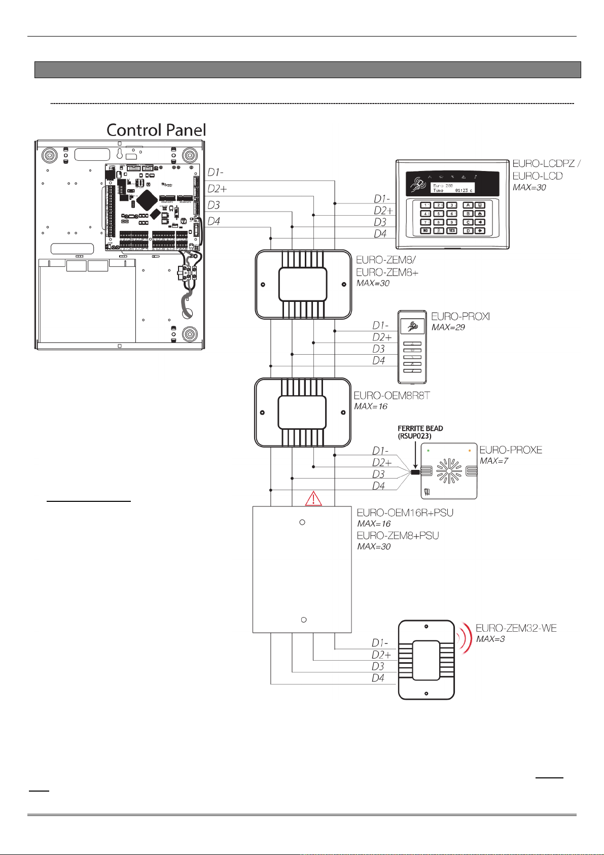
1.2.1 The EURO 280 Bus Diagram
EURO 280 Installation Manual
All EURO peripherals; LCD keypads,
readers, expanders etc. are connected
via the D1-, D2+, D3 and D4 terminals.
This is an example of what a typical
Euro 280 bus may look like.
General Principles:
NOTE 1: No alarm system cable should
be run with other cables carrying AC or
digital signals.
NOTE 2: The cables should be
protected by the use of grommets
where appropriate.
NOTE 3: For greater than 1000m range
standard isolated RS485 repeaters are
required.
NOTE 4: There MUST be a ferrite bead
fitted to the data wires of a EUROPROXE (if connected). The Ferrite bead
is supplied with the reader.
NOTE 5: (IMPORTANT!) If an expansion module with a power supply on board is connected, the D2+ terminal MUST
NOT be connected between the main bus and module.
Page: 4
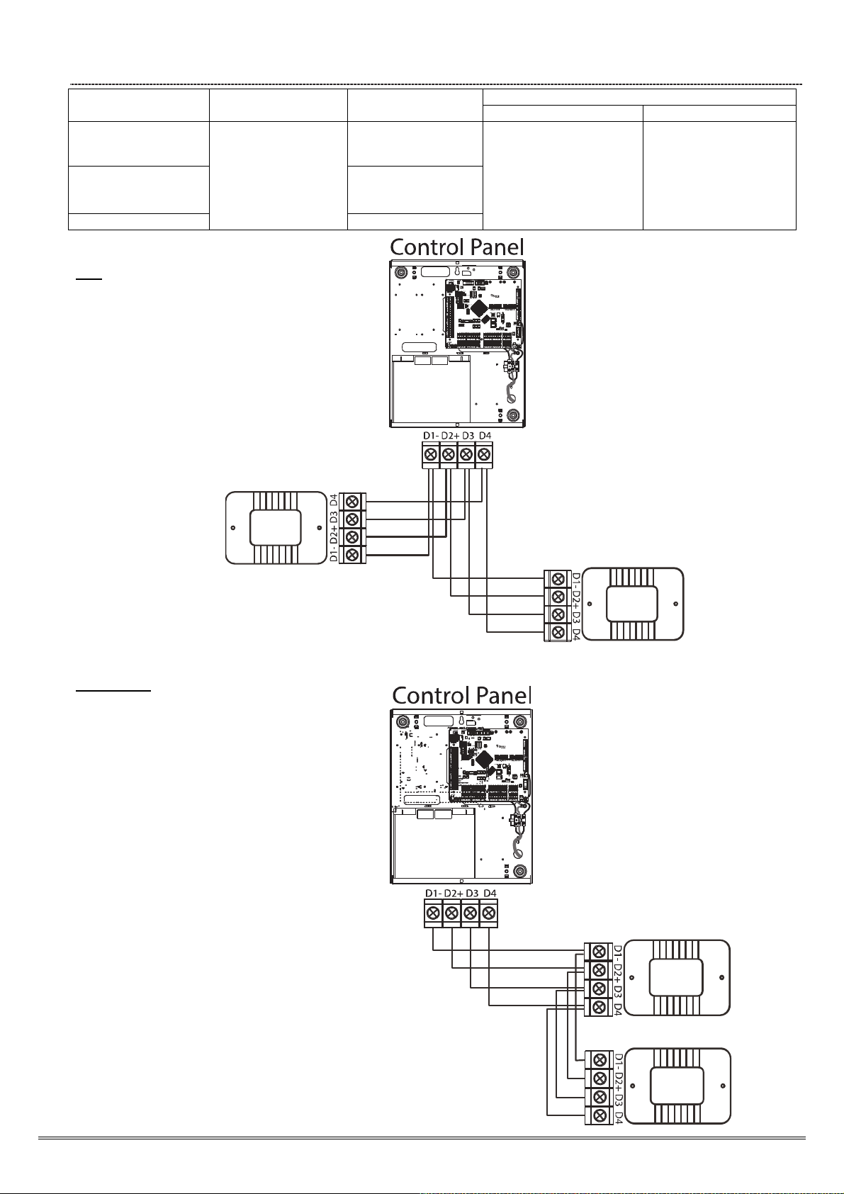
1.2.2 RS-485 Wiring
Cable type Screened Cable Bus range (m)
4 core alarm cable
6 core alarm cable
doubling D1 (0V) and
D2 (12V)
Twisted pair 1000m
Use when bus
located near
230VAC mains
power line
Star Wiring
Diagram
(Example #1)
Wiring Format
Daisy Chain Range Star Range
300m
1km 50m
1000m
Daisy Chain Wiring
Diagram
(Example #2)
Page: 5

EURO 280 Installation Manual
1.3 EURO 280 Input Mapping Table:
DEVICES Address Input Numbers
EURO 280 PCB PCB 1-8
0 9-16
1 17-24
2 25-32
3 33-40
4 41-48
EURO-ZEM8 / EURO-ZEM8+ / EURO-ZEM8+PSU / EURO-ZEM32-WE
EURO-ZEM8 / EURO-ZEM8+ / EURO-ZEM8+PSU
EURO-LCDPZ 0
EURO-LCDPZ / EURO-PROXI*
Total 280
5 49-56
6 57-64
7 65-72
8 73-80
9 81-88
10 89-96
11 97-104
12 105-112
13 113-120
14 121-128
15 129-136
16 137-144
17
18
19
20
21
22
23
24
25
26
27
28
29
1
2 253-254
3 255-256
4 257-258
5 259-260
6 261-262
7 263-264
8 265-266
9 267-268
10 269-270
11 271-272
12 273-274
13 275-276
14 277-278
15 279-280
145-152
153-160
161-168
169-176
177-184
185-192
193-200
201-208
209-216
217-224
225-232
233-240
241-248
249-250
251-252
NOTE 1: 3 x EURO-ZEM32-WE can be connected to the EURO 280. This expander allows 32 inputs which are
separated into 4 addresses (each address enables 8 wireless inputs). It is possible to mix the wired and wireless
remote expanders. When installing a EURO-ZEM32-WE, the first wireless expander will learn the 32 wireless
keyfobs and 2 wireless sounders. If this expander is disconnected, the keyfobs and sounders will need to be
learnt on another expander again.
*NOTE 2: If the EURO-PROXI (Internal Tag Reader) is programmed as a 'Set/Unset' device, 2 inputs can be
programmed. If the EURO-PROXI is programmed as 'Entry Control' or 'Access Control' only 1 input can be
programmed.
Page: 6

1.4 EURO 280 Output Mapping Table:
DEVICES Address Output Numbers
EURO 280 PCB PCB 4
ATE Outputs (using communication ribbon) Ribbon 9
0 1-16
1 1-16
2 1-16
3 1-16
4 1-16
5 1-16
6 1-16
EURO-OEM8R8T / EURO-OEM16R+PSU
EURO-ZEM8+ / EURO-ZEM8+PSU
EURO-LCDPZ 0 1
EURO-LCDPZ / EURO PROXI / EURO PROXE
(Continued overleaf)
7 1-16
8 1-16
9 1-16
10 1-16
11 1-16
12 1-16
13 1-16
14 1-16
15 1-16
0 1-4
1 1-4
2 1-4
3 1-4
4 1-4
5 1-4
6 1-4
7 1-4
8 1-4
9 1-4
10 1-4
11 1-4
12 1-4
13 1-4
14 1-4
15 1-4
16 1-4
17 1-4
18 1-4
19 1-4
20 1-4
21 1-4
22 1-4
23 1-4
24 1-4
25 1-4
26 1-4
27 1-4
28 1-4
29 1-4
1 1
2 1
3 1
4 1
5 1
6 1
7 1
8 1
9 1
10 1
11 1
12 1
13 1
14 1
Page: 7
EURO 280 Installation Manual
15 1
16 1
17 1
18 1
19 1
20 1
21 1
22 1
23 1
24 1
25 1
26 1
27 1
28 1
29 1
2. Installation
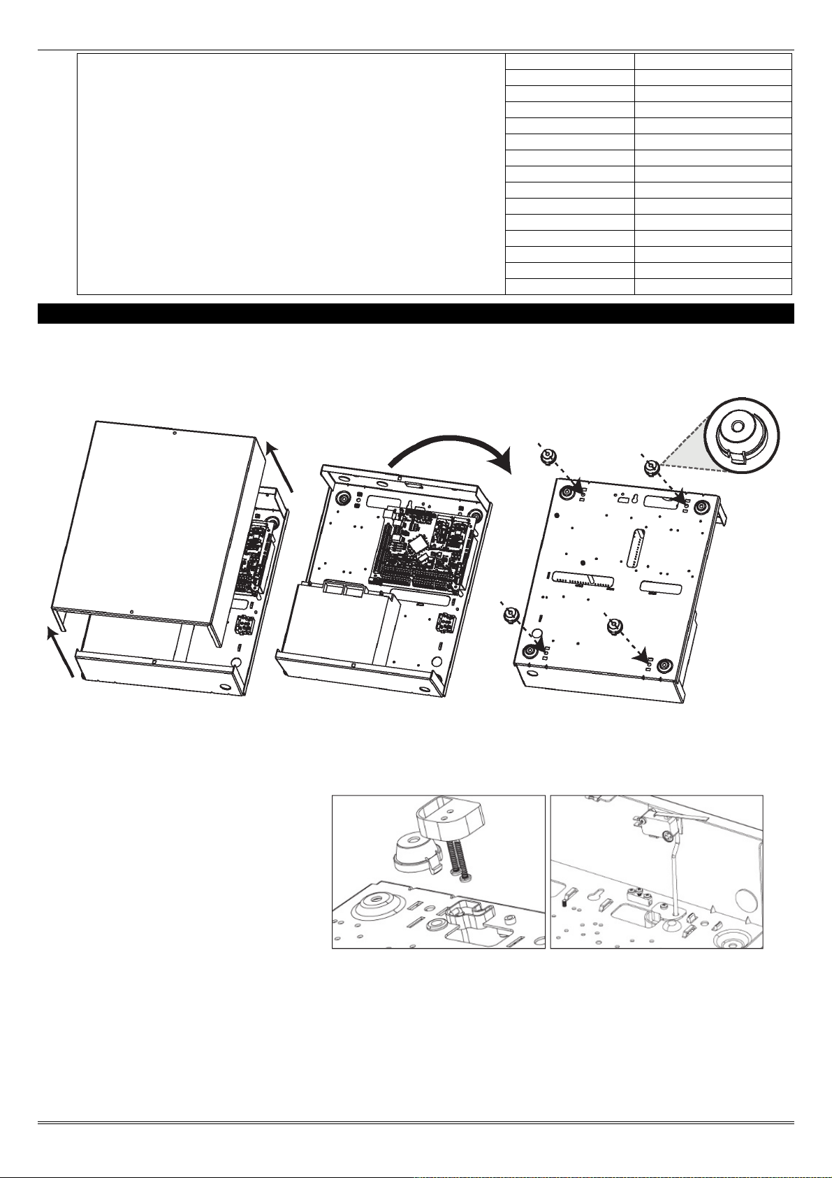
1. Unscrew and remove the cover of the EURO 280 control panel (Figure 1).
2. Install the supplied stand offs if needed before you mount the metal case to the wall (Figure 3).
Figure 1. Figure 2. Figure 3.
3. Screw the back metal plate to the wall.
4. The tamper mechanism comes
already fitted and will operate
properly once the casing is fitted
to the wall. If using the stand offs,
the following will need to be used
for the rear tamper mechanism
to work correctly.
5. If required, connect any other
devices (input expanders, output expanders etc.) before powering up the system.
6. The modem is already connected and will need the telephone line connecting. See page 48.
7. Secure all the wires and close the enclosure making sure the tamper is operational
8. Turn on the power to the EURO 280 control panel.
Page: 8
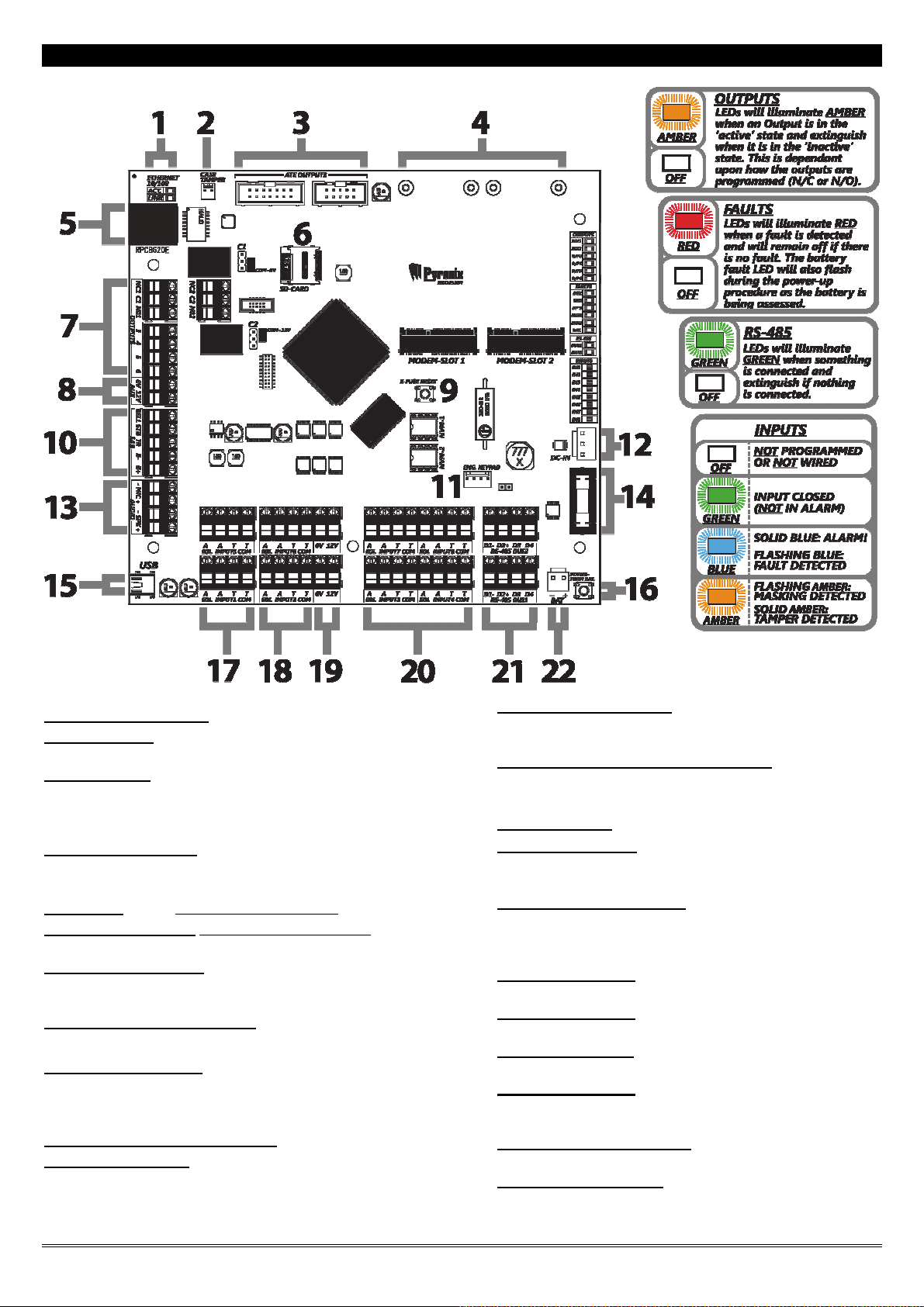
The Printed Circuit Board
1] Ethernet Status LEDs
2] Case Tamper
Connect the tamper switch cable here or use a jumper for Hold-off.
3] ATE Outputs
Connects the supplied communication loom to enable an additional 9
programmable outputs. These are low current and would normally be used
to connect a stand-alone communicator to the panel. See page: 12.
4] Modem Slots 1 & 2
Communications modules are inserted here. See page: 47
5] Ethernet (LAN)
(For future use – DO NOT USE)
6] Micro-SD Card Slot (For future use – DO NOT USE)
7] Output Connections
Output connection terminals (1- 6) see page:
8] Auxiliary 12V power supply
9] E-Fuse Reset Switch
Press to reset the switchable input / output / peripheral fuses once the
issue has been resolved.
10] External Sounder Connection
11] Engineer Keypad
An addressed keypad can be connected here to allow access to the
engineer menu. See page: 13.
12] 0V & 17V connection
Connects the 0V and 17V supply from the power supply
transformer (DC-IN).
13] Microphone & Speaker Connection
For future use
14] Battery Fuse
15] USB Connection
This connection is used to connect to a PC to allow uploading and
downloading of data using the InSite software (see page: 50).
16] Battery connect switch
Press to power up the control panel without the mains supply
connected. See page: 12.
17] Input Terminals
2 x Input terminals (block 1 and block 5)
18] Input Terminals
2 x Input terminals (block 2 and block 6)
19] 12V Power rails
2 x 12V Power rails
20] Input Terminals
4 x Input terminals (blocks 3, 4, 7 and 8)
21] 2 x RS485 bus terminals
Connects peripherals. See from page: 4.
22] Battery connection:
See page: 12.
Page: 9

EURO 280 Installation Manual
2.3 Technical Specification
Programmable Outputs Ratings Normal State Active State
Output 1 Relay, 3A, max 30V Normally Closed Normally Open
Output 2 Relay, 3A, max 30V Normally Closed Normally Open
Speaker 16 ohms No tones Repeat RKP tones & internal sounder
Strobe Output 500mA 12v 0v
Bell Output 500mA 12v 0v
ATE Outputs 2mA 5v 0v
All outputs are programmed in "CHANGE OUTPUTS" in the Engineer menu.
Input Resistance 1k / 1k DEOL Range 4k7 / 2k2 DEOL Range 4k7 / 4k7 DEOL Range
Normal 0k5 to 1k4 1k4 to 2k9 3k7 to 8k3
Burglary Alarm 1k5 to 5k9 4k2 to 7k8 8k4 to 10k2
Fault 6k to 8k1 8k to 11k3 10k3 to 14k9
Masking 8k2 to 17k 11k6 to 22k 15k to 22k
Tamper <0k5 or >17k <1k4 or >22k <3k7 or >23k
All inputs are programmed in "CHANGE INPUTS" in the Engineer menu.
Fuses Value Type
Bell fuse for Bell terminals 800mA
Inputs fuse for Input terminals 800mA
Auxiliary fuse for Aux terminals 800mA
RS485 Bus Fuse for bus terminals 800mA
Battery Fuse for battery terminals 3.15A anti-surge timed blow 250V Glass
Panel Power Supply Output Nominal Range
Output Voltage 15V DC 13.5-18V DC
Output Current 2.0A Continuous 0 ~ 3.4A
Power Supply Type A.
Maximum output peak ripple voltage: Max 120mVp-p
SD Voltage which the deep discharge protection function will operate at: 10.5V
Over Voltage Protection Trigger Voltage: 18.75V ~ 21.75V
NOTE 1. EURO 280 power supplies are NOT designed for use with multiple batteries connected.
NOTE 2. System load should not exceed the panel power supply output shown above, or the maximum load supportable by the battery for the
specified backup time, as in the table shown below.
NOTE 3. The power ratings are based on battery shown in table – but ANY battery capable of supporting the system load for the required time
may be used without affecting these ratings.
Panel Power Supply Input Nominal Range
Mains Supply Voltage AC 230V AC at 50Hz -15% +10%
PSU Rating 51VA 18.5V at 2.5A
Battery Charging Specification
Float Voltage 13.8v DC Current Limit 700mA
Battery low voltage cut off 10.5v Standby battery capacity 7A to 17A
Recharge time <24 Hours
EN50131-6:2008 Rated Output
In accordance with EN50131-6:2008, the control panel standby times and effective output currents depend on the Security Grade of the
system and how 230V mains missing fault is signaled to the Alarm Receiving Centre. Power supplies are rated in accordance with the
requirements of EN50131-6, which are related to the maximum battery size that can be accommodated in the housing and vary according to
the grade of the system in which they are installed, as per the following table:
Electrical Capability EN50131-6 Rating. Maximum Load
Example Battery Model Grade 2 Grade 3
Yuasa NP7-12 1.4A 0.9A
EN50131-1:2006+A1:2009 (30 hrs if notified to an ARC) for 17Ah battery = 477mA (Grade 3).
EN50131-1:2006+A1:2009 (60 hrs if not notified to an ARC) for 17Ah battery = 193mA (Grade 3).
E-fuse, resettable, non-replaceable
E-fuse, resettable, non-replaceable
E-fuse, resettable, non-replaceable
E-fuse, resettable, non-replaceable
Page: 10

EURO PCB Current Consumption Environmental
Quiescent 75-90mA Operational -10°C to +40°C, Certified
User Code and Tag Guessing Storage -20°C to +60°C
4-digit codes 10,000 Humidity 75%
6-digit codes 100,000 Dimensions
Disallowed codes None
All codes 1612
According to EN50131-3:2009 Annex B EURO Printed Circuit Board 159 x 175 x 25mm
According to spec of manufacturer of RFID components
used
Metal Casing
EN50131 Grading
EURO 280 Grade 3
(L) 390 x 305 x 100mm
Weight: 6kg
The below table specifies ATS (Alarm Transmission System) performance criteria in accordance with the
requirements of EN50136-1.
Notification Equipment
Remotely powered external
sounder
Self-powered external sounder Optional 1 Optional Optional
Main Communication Path (ATS) ATS 2 ATS 2 ATS 2 ATS 3
Second Communication Path (ATS) Optional Optional ATS 1 Optional
Notification Equipment Grade 3 Criteria
Option A Option B Option C Option D
Remotely powered external sounder 2 Optional Optional Optional
Self-powered external sounder Optional 1 Optional Optional
Main Communication Path (ATS) ATS 4 ATS 4 ATS 4 ATS 5
Second Communication Path (ATS) Optional Optional ATS 3 Optional
Option A Option B Option C Option D
2 Optional Optional Optional
Grade 2 Criteria
When used with a supervised premises transceiver, options 'Grade 3 Option D' are supported. The use of the Digi
Modem restricts the options up to 'Grade 2 Option B'.
2.1 Important Installation Notes
Ensure wiring is done to the national wiring regulations in the country where the installation is taking place. In
the UK, this is BS 7671 Requirements for electrical installations; IET Wiring Regulations (17th edition). If in
doubt, consult a local qualified electrician.
Ensure that a readily accessible disconnect device incorporated in the premises installation wiring shall be
provided external to the equipment with a contact separation of at least 3,0mm and connected as closely as
possible to the supply. Example: Unswitched Fused Spur Unit
When fixing external wires, ensure that means are provided in the installation to prevent the SELV (Safety
Electrical Low Voltage) or signal circuits from coming into contact with live parts of the power supply circuit.
Wires shall be fixed near their terminal blocks.
The end of stranded conductor shall not be consolidated by soft soldering at places where the conductor is
subjected to contact pressure. Example: Must not solder ends of wires which are to be secured in detector and
control panel terminal connectors.
On completion of wiring use tie-wraps to prevent any loose wires causing a safety hazard (material of cables tie
shall be rated at least HB or better).
Cables ties and hoses shall be separate for power supply cable and SELV (Safety Electrical Low Voltage) wirings.
Size of protective bonding conductors: minimum section 1.5mm². Example: Electrical Earth wire connections.
Page: 11
EURO 280 Installation Manual
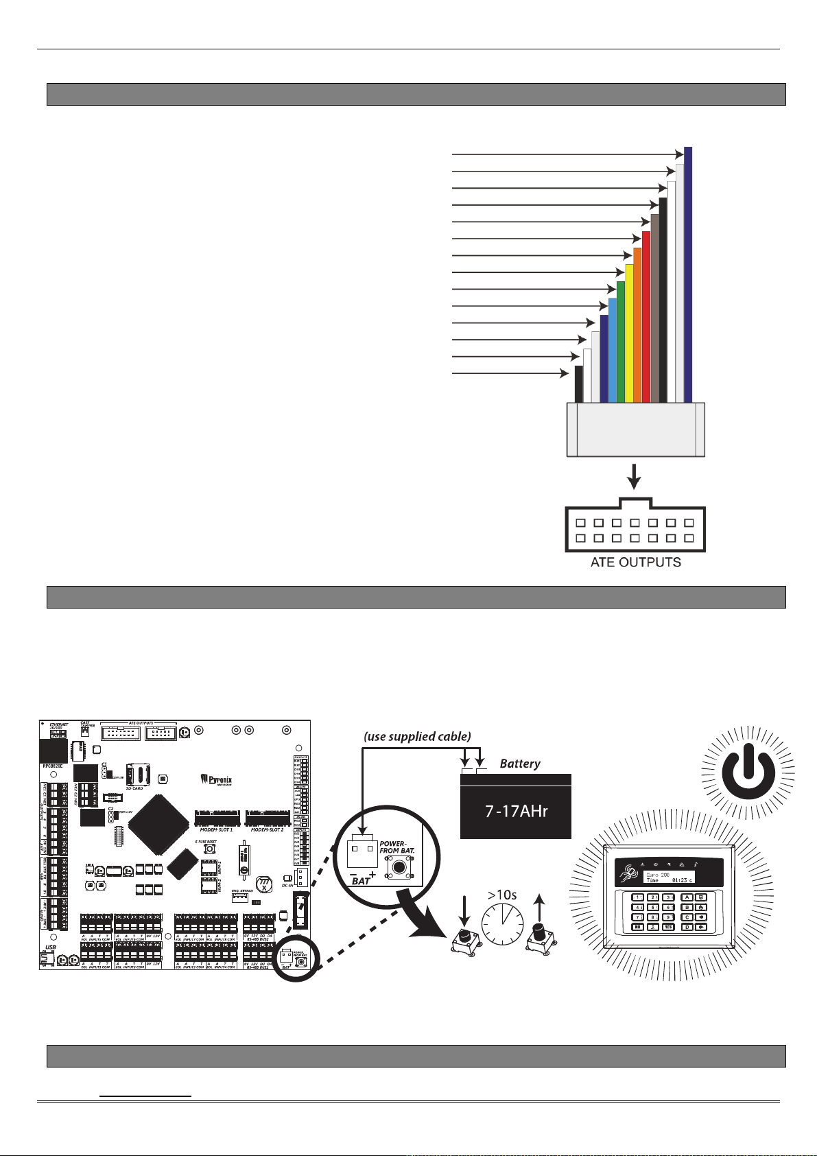
2.2 Communication ATE Loom
ATE low power outputs are programmed in the engineer menu: “CHANGE OUTPUTS->Endstation Outputs”.
Purple (ATE Output 8: Mains Fail (0052))
Light Grey (ATE Output 10: Test ATS (0064))
White (ATE Output 9: Global Fault 2 (0056))
Black (ATE Output 7: Confirmed Any (0006))
Brown (ATE Output 4: Final Set All (0004))
Red (0V)
Orange (ATE Output 2: HU Device Any (0009))
Yellow (ATE Output 3: Unconfirmed Any (0018))
Green (ATE Output 6: Omit Rearm Any (0017)))
Blue (ATE Output 1: Fire (0001))
Purple (ATE Output 5: Tamper Any (0007))
Light Grey (+12V)
White (DO NOT USE)
Black (Line Fault)
Normal Status: 5V
Active Status: 0V
Current: 2mA
The polarity of the ATE outputs can be inverted from the
function 'SITE OPTIONS' under 'Invert ATE Outputs'.
2.3 Battery Connection
The back-up battery is an essential part of this security system in the event of a mains failure (malicious or otherwise). It
can also be used to power the panel without mains so that the panel can be programmed before the mains supply to a
building has been established (e.g. in a new-build property).
NOTE: The battery connect button is only used if no mains is present and a battery power up is required.
2.4 AC Mains Supply Connection
Control Panel
Page: 12
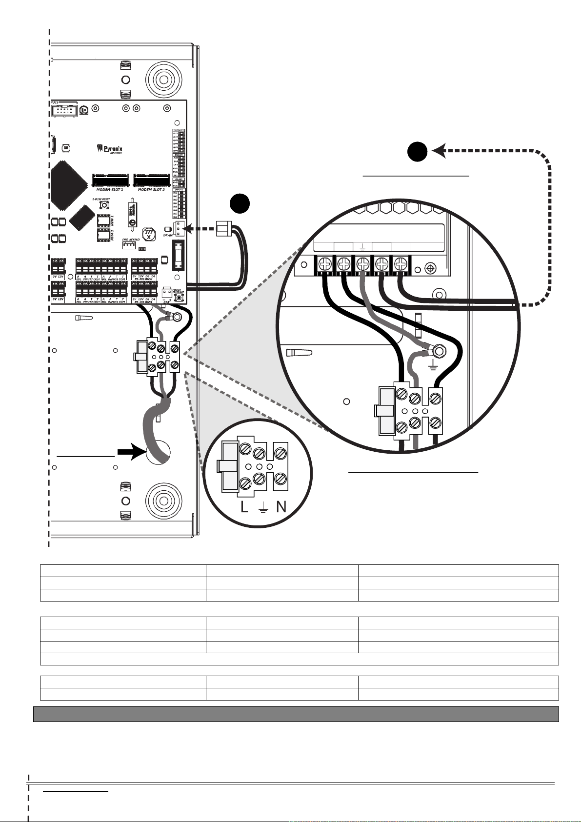
A
Connects to DC-IN
(DC-IN)
(See Fig. A)
A
L N -V +V
MAINS IN:
VIEW: PSU TERMINALS
(Underneath Main PCB)
Panel Power Supply Input Nominal Range
Mains Supply Voltage AC 230V AC at 50Hz -15% +10%
PSU Rating 51VA 18.5V at 2.5A
Panel Power Supply Output Nominal Range
Output Voltage 15V DC 13.5-18V DC
Output Current 2.0A Continuous 2.5A peak, during battery charging
Power Supply Type A.
Fuses Value Type
230V Mains Fuse for mains terminals T500mA anti-surge slow blow 250V Ceramic
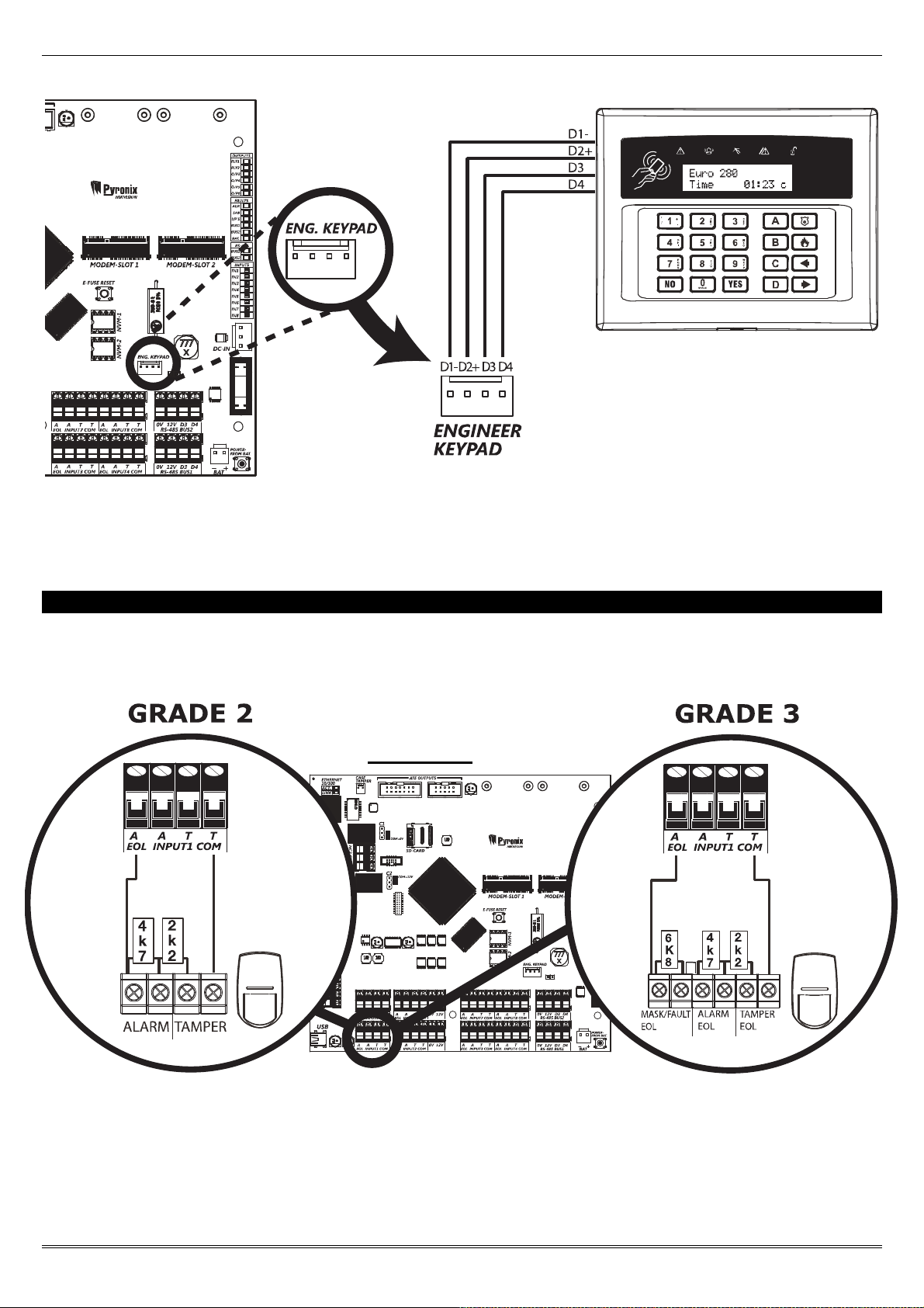
2.5 Engineer Keypad Connection
If required, any keypad can be connected to the 'Engineer Keypad' connections as shown below. This enables quick
access to the Engineer menu without having to walk to the nearest keypad.
Control Panel
Page: 13
EURO 280 Installation Manual
NOTE: Before an Engineer keypad is enabled, it should be addressed as an additional keypad on the control panel
before operation. See page: 19 for adding keypads to the control panel.
3. Input Connections
Here are some examples of a typical connection to a wired detector, for grade 2 and grade 3 respectively:
Control Panel
Page: 14
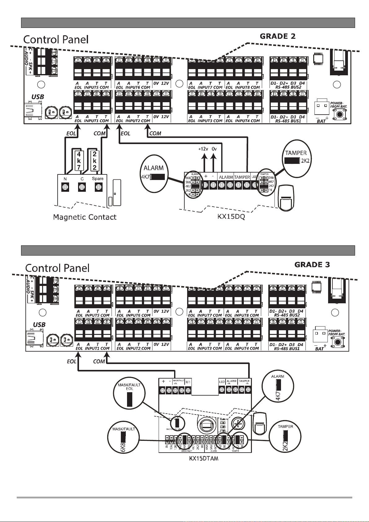
3.1 Default Grade 2 DEOL (Double End of Line) Input Wiring
The above wiring example shows the connections for a Grade 2 KX15DQ PIR detector.
3.2 Grade 3 Mask/Fault Input Wiring
The above wiring example shows the connections for a Grade 3 KX15DTAM detector.
Page: 15
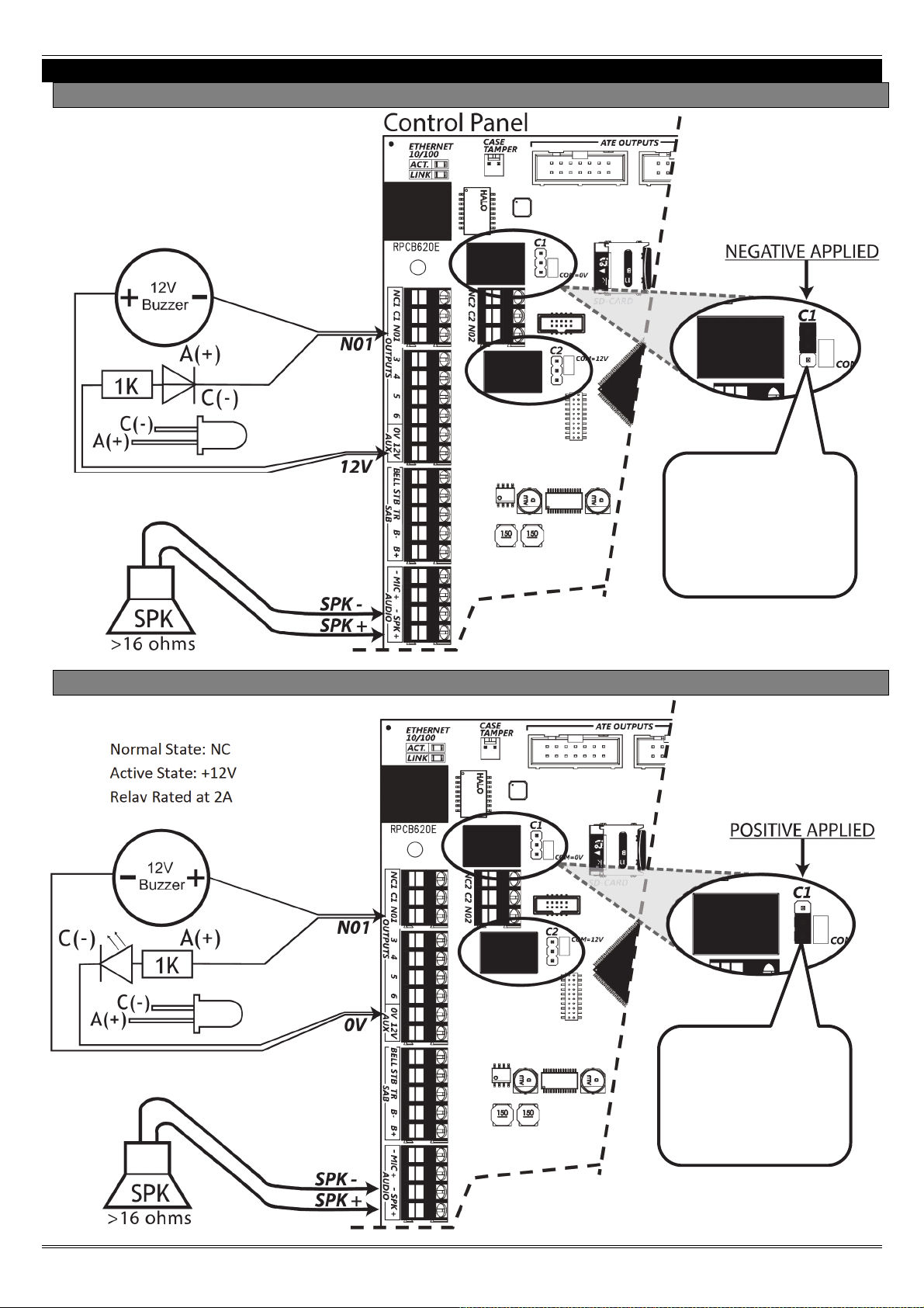
4. Output (PGM) Connections
4.1 Negative Applied Wiring
Normal State: NC
Active State: 0V
Relay Rated at 2A
EURO 280 Installation Manual
Place the jumper /
link in the position
shown to set the
wiring to negative
applied.
4.2 Positive Applied Wiring
Normal State: NC
Active State: +12V
Place the jumper /
link in the position
shown to set the
wiring to positive
applied.
Page: 16
 Loading...