

Page 1

ERT-F204x • ERT-F208x • ERT-F216x
Digital Video Recorder
User Manual
Page 2

ERT-F2xxx DVR User Manual
Manual Illustrations and Features
Graphics (screen shots, product pictures, etc.) in this document are for illustrative purposes only. Your actual
product may differ in appearance. Your product might not support all features discussed in this document.
Hikvision USA Inc., 18639 Railroad St., City of Industry, CA 91748, USA • Hikvision Canada, 4848 rue Levy,
Saint Laurent, Quebec, Canada, H4R 2P1
Telephone: +1-909-895-0400 • Toll Free in USA: +1-866-200-6690 • E-Mail: sales.usa@hikvision.com •
www.hikvision.com
© 2018 Hikvision USA Inc. • All Rights Reserved • Any and all information, including, among others, wordings,
pictures, and graphs are the properties of Hangzhou Hikvision Digital Technology Co., Ltd., or its subsidiaries
(hereinafter referred to as “Hikvision”).
ALL RIGHTS RESERVED.
This user manual (hereinafter referred to be “the Manual”) cannot be reproduced, changed, translated, or
distributed, partially or wholly, by any means, without the prior written permission of Hikvision. Unless
otherwise stipulated, Hikvision does not make any warranties, guarantees or representations, express or
implied, regarding to the Manual.
About this Manual
The Manual includes instructions for using and managing the product. Pictures, charts, images and all other
information hereinafter are for description and explanation only. The information contained in the Manual is
subject to change, without notice, due to firmware updates or other reasons. Please find the latest version in
the company Web site (http://overseas.hikvision.com/en/).
Please use this user manual under the guidance of professionals.
Trademarks Acknowledgement
and other Hikvision trademarks and logos are the properties of Hikvision in various jurisdictions.
Other trademarks and logos mentioned below are the properties of their respective owners.
Legal Disclaimer
TO THE MAXIMUM EXTENT PERMITTED BY APPLICABLE LAW, THE PRODUCT DESCRIBED, WITH ITS HARDWARE,
SOFTWARE AND FIRMWARE, IS PROVIDED “AS IS”, WITH ALL FAULTS AND ERRORS, AND HIKVISION MAKES NO
WARRANTIES, EXPRESS OR IMPLIED, INCLUDING WITHOUT LIMITATION, MERCHANTABILITY, SATISFACTORY
QUALITY, FITNESS FOR A PARTICULAR PURPOSE, AND NON-INFRINGEMENT OF THIRD PARTY. IN NO EVENT
WILL HIKVISION, ITS DIRECTORS, OFFICERS, EMPLOYEES, OR AGENTS BE LIABLE TO YOU FOR ANY SPECIAL,
CONSEQUENTIAL, INCIDENTAL, OR INDIRECT DAMAGES, INCLUDING, AMONG OTHERS, DAMAGES FOR LOSS
OF BUSINESS PROFITS, BUSINESS INTERRUPTION, OR LOSS OF DATA OR DOCUMENTATION, IN CONNECTION
WITH THE USE OF THIS PRODUCT, EVEN IF HIKVISION HAS BEEN ADVISED OF THE POSSIBILITY OF SUCH
DAMAGES.
REGARDING TO THE PRODUCT WITH INTERNET ACCESS, THE USE OF PRODUCT SHALL BE WHOLLY AT YOUR
OWN RISKS. HIKVISION SHALL NOT TAKE ANY RESPONSIBILITES FOR ABNORMAL OPERATION, PRIVACY
LEAKAGE OR OTHER DAMAGES RESULTING FROM CYBER ATTACK, HACKER ATTACK, VIRUS INSPECTION, OR
OTHER INTERNET SECURITY RISKS; HOWEVER, HIKVISION WILL PROVIDE TIMELY TECHNICAL SUPPORT IF
REQUIRED.
SURVEILLANCE LAWS VARY BY JURISDICTION. PLEASE CHECK ALL RELEVANT LAWS IN YOUR JURISDICTION
BEFORE USING THIS PRODUCT IN ORDER TO ENSURE THAT YOUR USE CONFORMS THE APPLICABLE LAW.
HIKVISION SHALL NOT BE LIABLE IN THE EVENT THAT THIS PRODUCT IS USED WITH ILLEGITIMATE PURPOSES.
IN THE EVENT OF ANY CONFLICTS BETWEEN THIS MANUAL AND THE APPLICABLE LAW, THE LATER PREVAILS.
UM ERT-F2xxx 030118NA 1
Page 3
ERT-F2xxx DVR User Manual
Regulatory Information
FCC Information
Please take attention that changes or modification not expressly approved by the party responsible for
compliance could void the user’s authority to operate the equipment.
FCC Compliance: This equipment has been tested and found to comply with the limits for a Class A digital
device, pursuant to part 15 of the FCC Rules. These limits are designed to provide reasonable protection
against harmful interference when the equipment is operated in a commercial environment. This equipment
generates, uses, and can radiate radio frequency energy and, if not installed and used in accordance with the
instruction manual, may cause harmful interference to radio communications. Operation of this equipment in
a residential area is likely to cause harmful interference in which case the user will be required to correct the
interference at his own expense.
FCC Conditions
This device complies with part 15 of the FCC Rules. Operation is subject to the following two conditions:
1. This device may not cause harmful interference.
2. This device must accept any interference received, including interference that may cause undesired
operation.
EU Conformity Statement
This product and, if applicable, the supplied accessories too are marked with “CE” and comply
therefore with the applicable harmonized European standards listed under the EMC Directive
2014/30/EU, the LVD Directive 2014/35/EU, the RoHS Directive 2011/65/EU.
2012/19/EU (WEEE Directive): Products marked with this symbol cannot be disposed of as unsorted
municipal waste in the European Union. For proper recycling, return this product to your local
supplier upon the purchase of equivalent new equipment, or dispose of it at designated collection
points. For more information see: www.recyclethis.info
2006/66/EC (Battery Directive): This product contains a battery that cannot be disposed of as
unsorted municipal waste in the European Union. See the product documentation for specific
battery information. The battery is marked with this symbol, which may include lettering to indicate
cadmium (Cd), lead (Pb), or mercury (Hg). For proper recycling, return the battery to your supplier or
to a designated collection point. For more information see: www.recyclethis.info
Industry Canada ICES-003 Compliance
This device meets the CAN ICES-3 (A)/NMB-3(A) standards requirements.
UM ERT-F2xxx 030118NA 2
Page 4

ERT-F2xxx DVR User Manual
Mandatory Electrical Requirements
Hikvision requires the following conditions and equipment for all of its electronic equipment:
• Grounding
Ensure good conductivity for all ground paths; examine ground path contact surfaces for defects, dirt,
corrosion, or non-conductive coatings that may impede conductivity. Repair or clean contact surfaces as
necessary to assure good metal-to-metal contact. Ensure fasteners are properly installed and tightened.
• Electrical Wiring
Ensure your outlets are properly wired. They can be checked with an electrical outlet tester.
• Surge Suppressor (Required)
Hikvision is not responsible for any damage to equipment caused by power spikes in the electrical power
grid. Use of a surge suppressor meeting the following specifications is mandatory for all Hikvision
electronic equipment:
• Specifications
˗ Listed by Underwriter’s Laboratories, meeting the UL 1449 Voltage Protection Rating (VPR)
˗ Minimum protection of 1,000 joules or higher
˗ Clamping voltage of 400 V or less
˗ Response time of 1 nanosecond or less
• Usage
˗ Surge suppressors must not be daisy chained with power strips or other surge suppressors
• Maintenance
˗ Replace after a serious electrical event (e.g., lighting blew out a transformer down the street)
˗ Replace yearly in storm-prone areas
˗ Replace every two years as routine maintenance
Safety Instructions
Proper configuration of all passwords and other security settings is the responsibility of the installer and/or
end-user.
In the use of the product, you must be in strict compliance with the electrical safety regulations of the nation
and region. Please refer to technical specifications for detailed information.
Input voltage should meet both the SELV (Safety Extra Low Voltage) and the Limited Power Source with 100 to
240 VAC, 48 VDC or 12 VDC according to the IEC60950-1 standard. Please refer to technical specifications for
detailed information.
Do not connect several devices to one power adapter as adapter overload may cause over-heating or a fire
hazard.
Please make sure that the plug is firmly connected to the power socket.
If smoke, odor, or noise rise from the device, turn off the power at once and unplug the power cable, and then
please contact the service center.
Preventive and Cautionary Tips
Before connecting and operating your device, please be advised of the following tips:
UM ERT-F2xxx 030118NA 3
Page 5
ERT-F2xxx DVR User Manual
Series
Model
ERT-F204x
ERT-F208x
ERT-F216x
Symbol
Description
Provides additional information to emphasize or supplement
important points of the main text.
Indicates a potentially hazardous situation, which if not avoided,
degradation, or unexpected results.
Indicates a hazard with a high level of risk, which if not avoided, will
result in death or serious injury.
Ensure unit is installed in a well-ventilated, dust-free environment.
Unit is designed for indoor use only.
Keep all liquids away from the device.
Ensure environmental conditions meet factory specifications.
Ensure unit is properly secured to a rack or shelf. Major shocks or jolts to the unit as a result of dropping it
may cause damage to the sensitive electronics within the unit.
Use the device in conjunction with an UPS if possible.
Power down the unit before connecting and disconnecting accessories and peripherals.
A factory recommended HDD should be used for this device.
Improper use or replacement of the battery may result in hazard of explosion. Replace with the same or
equivalent type only. Dispose of used batteries according to the instructions provided by the manufacturer.
Applicable Models
This manual is applicable to the models listed in the following table.
ERT-F2xxx
Symbol Conventions
The symbols that may be found in this document are defined as follows.
could result in equipment damage, data loss, performance
Product Key Features
General
• Connectable to network cameras, network dome, and encoders
• Connectable to third-party network cameras via HIK, private RTSP protocols
• Connectable to the smart IP cameras
• PAL/NTSC adaptive video inputs
• Supports H.264+/H.264 video streams
• Each channel supports dual-stream
• Up to two 2 MP network cameras can be connected
• Independent configuration for each channel, including resolution, frame rate, bit rate, image quality, etc.
UM ERT-F2xxx 030118NA 4
Page 6

ERT-F2xxx DVR User Manual
• The quality of the input and output record is configurable
Local Monitoring
• HDMI™/VGA outputs at up to 1920 × 1080 resolution
• Multiple screen display in live view is supported, and the display sequence of channels is adjustable
• Live view screen can be switched in group, and manual switch and automatic cycle live view are also
provided, and the interval of automatic cycle can be adjusted
• Configurable main stream and sub-stream for the live view
• Quick setting menu is provided for live view
• Motion detection, video tampering, VCA (Video Content Analysis) alarm, video exception alert and video
loss alert functions
• Privacy mask
• Multiple PTZ protocols supported; PTZ preset, patrol and pattern
• Zooming in by clicking the mouse and PTZ tracing by dragging mouse
HDD Management
• 1 SATA hard disk can be connected, with a maximum of 6 TB storage capacity
• Supports S.M.A.R.T. and bad sector detection
• HDD quota management; different capacity can be assigned to different channel
Recording and Playback
• Holiday recording schedule configuration
• Continuous and event video recording parameters.
• Multiple recording types: manual, continuous, alarm, motion, motion | alarm, motion & alarm
• Eight recording time periods with separated recording types each day
• Pre-record and post-record for alarm, motion detection for recording, and pre-record time for schedule
and manual recording
• Searching record files by events (alarm input/motion detection/VCA).
• Playback by sub-periods
• Tag adding for record files, searching and playing back by tags
• Locking and unlocking record files
• Provides new playback interface with easy and flexible operation.
• Searching and playing back record files by camera no., recording type, start time, end time, etc.
• Smart search for the selected area in the video
• Zooming in when playback
• Reverse playback of multi-channel
• Supports pause, play reverse, speed up, speed down, skip forward, and skip backward when playback, and
locating by dragging the mouse
• Supports thumbnails view and fast view during playback
• Supports playback by transcoded stream
• Up to 4/8-ch synchronous playback
UM ERT-F2xxx 030118NA 5
Page 7

ERT-F2xxx DVR User Manual
Backup
• Export video data by USB or SATA device
• Export video clips when using playback
• Management and maintenance of backup devices
Alarm and Exception
• Alarm for video loss, motion detection, VCA, video tampering, HDD full, HDD error, network disconnected,
IP confliction, illegal login, abnormal record, etc.
• Alarm triggers full screen monitoring, audio alarm, notifying surveillance center, and sending e-mail
• Automatic restore when system is abnormal
• Supports line crossing detection and intrusion detection
• VCA alarm message push via iVMS-4500 mobile client software
Other Local Functions
• Three-level user management; admin user is allowed to create many operating accounts and define their
operating permission, which includes the limit to access any channel
• Admin password resetting by exporting/importing the GUID file
• Operation, alarm, exceptions and log recording and searching
• Manually triggering and clearing alarms
• Import and export of device configuration information
Network Functions
• 10 /100/1000 Mbps self-adaptive Ethernet interface
• IPv6 is supported
• TCP/IP protocol, DHCP, DNS, DDNS, NTP, SADP, and SMTP are supported
• TCP, UDP, and RTP for unicast
• Auto/Manual port mapping by UPnP™
• Supports access by Hik-Connect
• Remote reverse playback via RTSP
• Remote search, playback, download, locking and unlocking of the record files, and the breakpoint resume
is supported for downloading files
• Remote viewing of the device status, system logs, and alarm status
• Remote keyboard operation
• Remote locking and unlocking of control panel and mouse
• Remote HDD formatting and program upgrading
• Remote system restart and shutdown
• Alarm and exception information can be sent to the remote host
• Remotely start/stop recording
• Remote PTZ control (depending on models)
• Remote JPEG capture
• Two-way audio and voice broadcasting
• Embedded Web server
UM ERT-F2xxx 030118NA 6
Page 8

ERT-F2xxx DVR User Manual
• Upgrade by FTP server
Development Scalability
• SDK for Windows and Linux system
• Source code of application software for demo
• Development support and training for application system
UM ERT-F2xxx 030118NA 7
Page 9

ERT-F2xxx DVR User Manual
TABLE OF CONTENTS
Chapter 1 Introduction ......................................................................................................................................... 11
USB Mouse Operation ........................................................................................................................ 11
Rear Panels .......................................................................................................................................... 12
Chapter 2 Getting Started ..................................................................................................................................... 13
Device Startup and Activation ............................................................................................................ 13
Starting Up and Shutting Down the DVR ................................................................................... 13
Activating Your Device ............................................................................................................... 14
Using the Unlock Pattern for Login ............................................................................................ 16
Login and Logout ........................................................................................................................ 18
Resetting Your Password ........................................................................................................... 20
Using the Setup Wizard for Basic Configuration ................................................................................. 21
Adding and Enabling Analog Cameras ................................................................................................ 23
Adding and Connecting IP Cameras .................................................................................................... 23
Activating IP Cameras ................................................................................................................ 23
Adding Online IP Cameras.......................................................................................................... 24
Editing the Connected IP Cameras and Configuring Customized Protocols .............................. 28
Enabling ONVIF .......................................................................................................................... 30
Chapter 3 Live View .............................................................................................................................................. 31
Live View Status Icons ......................................................................................................................... 31
Operations in Live View Mode ............................................................................................................ 31
Right-Click Menu ........................................................................................................................ 31
Quick Setting Toolbar in Live View Mode .................................................................................. 32
Adjusting Live View Settings ............................................................................................................... 34
Chapter 4 PTZ Controls ......................................................................................................................................... 37
Configuring PTZ Settings ..................................................................................................................... 37
Setting PTZ Presets, Patrols, and Patterns .......................................................................................... 38
Customizing Presets ................................................................................................................... 38
Calling Presets ............................................................................................................................ 39
Customizing Patrols ................................................................................................................... 39
Calling Patrols............................................................................................................................. 40
Customizing Patterns ................................................................................................................. 41
Calling Patterns .......................................................................................................................... 42
Customizing Linear Scan Limit ................................................................................................... 42
Calling Linear Scan ..................................................................................................................... 43
One-Touch Park ......................................................................................................................... 43
PTZ Control Panel ..................................................................................................................... 44
Chapter 5 Recording Settings ............................................................................................................................... 46
Configuring Parameters ...................................................................................................................... 46
Configuring Recording Schedule ......................................................................................................... 49
Configuring Motion Detection Recording ........................................................................................... 51
UM ERT-F2xxx 030118NA 8
Page 10
ERT-F2xxx DVR User Manual
Configuring Alarm Triggered Recordings ............................................................................................ 53
Configuring VCA Event Recording ....................................................................................................... 55
Manual Recording ............................................................................................................................... 56
Configuring Holiday Recording ........................................................................................................... 57
Files Protection ................................................................................................................................... 58
Locking the Recording Files ........................................................................................................ 58
Setting HDD Property to Read-only ........................................................................................... 60
Chapter 6 Playback ............................................................................................................................................... 62
Playing Back Record Files .................................................................................................................... 62
Instant Playback ......................................................................................................................... 62
Playing Back by Normal Search .................................................................................................. 62
Playing back by Smart Search .................................................................................................... 65
Playing Back by Event Search ..................................................................................................... 67
Playing Back by Tag .................................................................................................................... 69
Playing Back by System Logs ...................................................................................................... 71
Playing Back External Files ......................................................................................................... 73
Playing Back by Sub-Periods ...................................................................................................... 73
Auxiliary Playback Functions ............................................................................................................... 74
Playing Back Frame-by-Frame ................................................................................................... 74
Fast View .................................................................................................................................... 75
Digital Zoom ............................................................................................................................... 75
File Management ....................................................................................................................... 76
Chapter 7 Backup .................................................................................................................................................. 77
Backing up Record Files ...................................................................................................................... 77
Backing up by Normal Video Search .......................................................................................... 77
Backing Up by Event Search ....................................................................................................... 79
Backing Up Video Clips ............................................................................................................... 80
Managing Backup Devices .................................................................................................................. 81
Chapter 8 Alarm Settings ...................................................................................................................................... 82
Setting Motion Detection Alarm ......................................................................................................... 82
Setting Sensor Alarms ......................................................................................................................... 84
Detecting Video Loss Alarm ................................................................................................................ 86
Detecting Video Tampering Alarm...................................................................................................... 88
Line Crossing Detection Alarm ............................................................................................................ 89
Intrusion Detection Alarm .................................................................................................................. 91
Handling Exceptions Alarm ................................................................................................................. 92
Setting Alarm Response Actions ......................................................................................................... 93
Triggering or Clearing Alarm Output Manually .................................................................................. 96
Chapter 9 Network Settings .................................................................................................................................. 97
Configuring General Settings .............................................................................................................. 97
Configuring Advanced Settings ........................................................................................................... 97
Configuring Hik-Connect ............................................................................................................ 97
Configuring DDNS..................................................................................................................... 100
UM ERT-F2xxx 030118NA 9
Page 11

ERT-F2xxx DVR User Manual
Configuring NTP Server ............................................................................................................ 102
Configuring More Settings ....................................................................................................... 103
Configuring E-Mail ................................................................................................................... 104
Configuring NAT ....................................................................................................................... 106
Checking Network Traffic ......................................................................................................... 109
Configuring Network Detection ........................................................................................................ 110
Testing Network Delay and Packet Loss .................................................................................. 110
Exporting Network Packet ....................................................................................................... 111
Checking the Network Status ................................................................................................... 111
Checking Network Statistics..................................................................................................... 112
Chapter 10 HDD Management ........................................................................................................................... 114
Initializing HDDs .............................................................................................................................. 114
Configuring Quota Mode ................................................................................................................ 115
HDD Detection ................................................................................................................................ 116
Configuring HDD Error Alarms ........................................................................................................ 118
Chapter 11 Camera Settings ............................................................................................................................... 120
Configuring OSD Settings ................................................................................................................ 120
Configuring Privacy Mask ................................................................................................................ 120
Configuring Video Parameters ........................................................................................................ 121
Chapter 12 Device Management and Maintenance ........................................................................................... 123
Viewing System Information ........................................................................................................... 123
Searching and Exporting Log Files................................................................................................... 123
Importing/Exporting Configuration Files ........................................................................................ 125
Upgrading System ........................................................................................................................... 127
Upgrading by Local Backup Device ........................................................................................ 127
Upgrading by FTP ................................................................................................................... 127
Restoring Default Settings .............................................................................................................. 128
Chapter 13 Others ............................................................................................................................................... 129
Configuring General Settings .......................................................................................................... 129
Configuring DST Settings ................................................................................................................. 130
Configuring More Settings for Device Parameters ......................................................................... 130
Managing User Accounts ................................................................................................................ 131
Adding a User ......................................................................................................................... 131
Deleting a User ....................................................................................................................... 135
Editing a User ......................................................................................................................... 135
Appendix ............................................................................................................................................................. 138
Glossary ........................................................................................................................................... 138
Troubleshooting .............................................................................................................................. 139
UM ERT-F2xxx 030118NA 10
Page 12
ERT-F2xxx DVR User Manual
No.
Icon
Description
Name
Action
Description
Single-Click
Live view: Select channel and show the quick set menu
Menu: Select and enter
Double-Click
Live view: Switch between single-screen and multi-screen
Click and Drag
PTZ control: pan, tilt and zoom
Live view: Drag channel/time bar
Right-Click
Single-Click
Live view: Show menu
Menu: Exit current menu to upper level menu
Scroll-Wheel
Scrolling up
Live view: Previous screen
Menu: Previous item
Scrolling down
Live view: Next screen
Menu: Next item
Chapter 1 Introduction
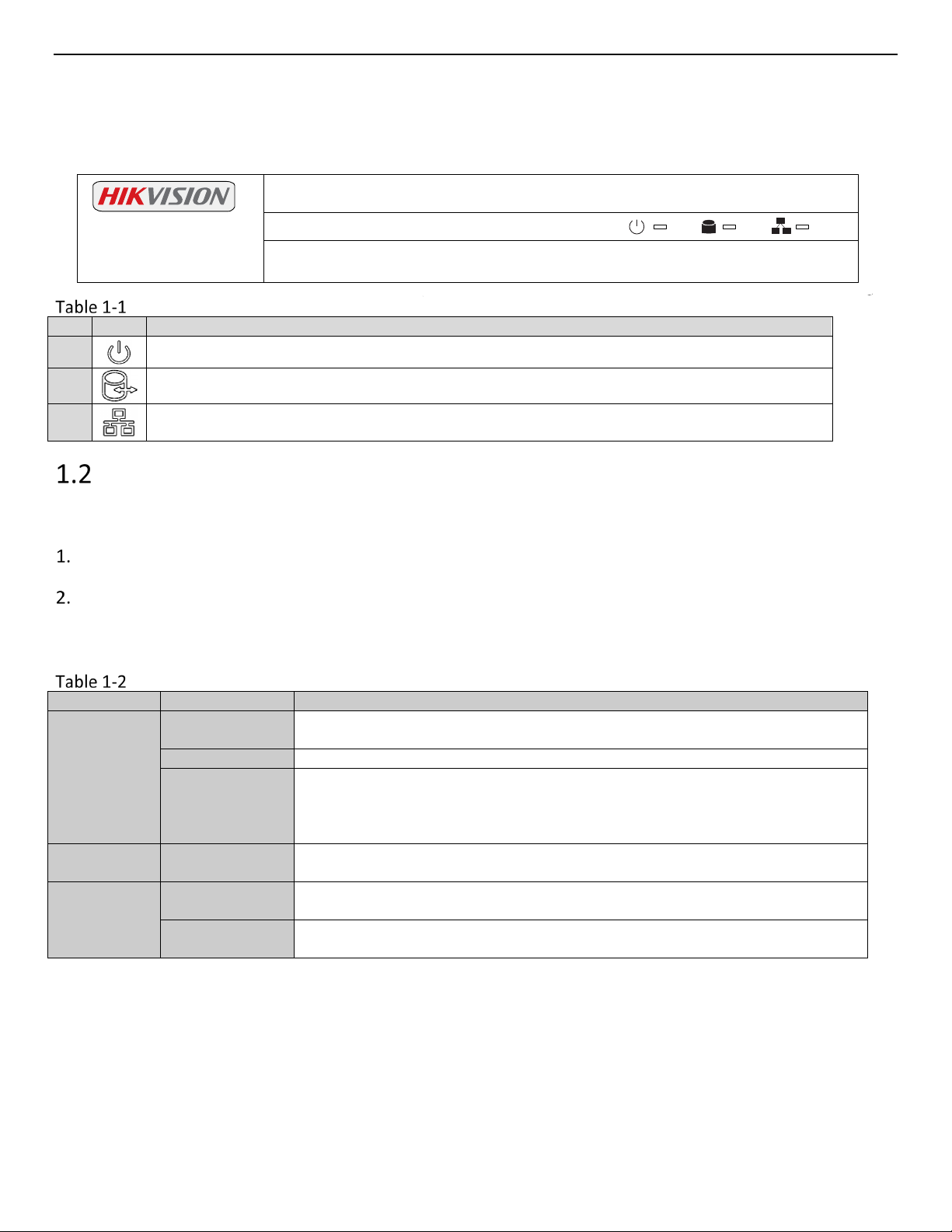
Description of Front Panel
1
2
3
Indicator turns green when DVR is powered up.
Indicator lights when data is being read from or written to HDD.
Indicator blinks when network connection is functioning properly.
USB Mouse Operation
A regular 3-button (Left/Right/Scroll-wheel) USB mouse can also be used with this DVR.
Plug USB mouse into one of the USB interfaces on the front panel of the DVR.
The mouse should automatically be detected. If in a rare case that the mouse is not detected, the possible
reason may be that the two devices are not compatible, please refer to the recommended the device list
from your provider.
Description of the Mouse Control
Left-Click
Video tampering, privacy mask and motion detection: Select target area
Digital zoom-in: Drag and select target area
UM ERT-F2xxx 030118NA 11
Page 13
ERT-F2xxx DVR User Manual
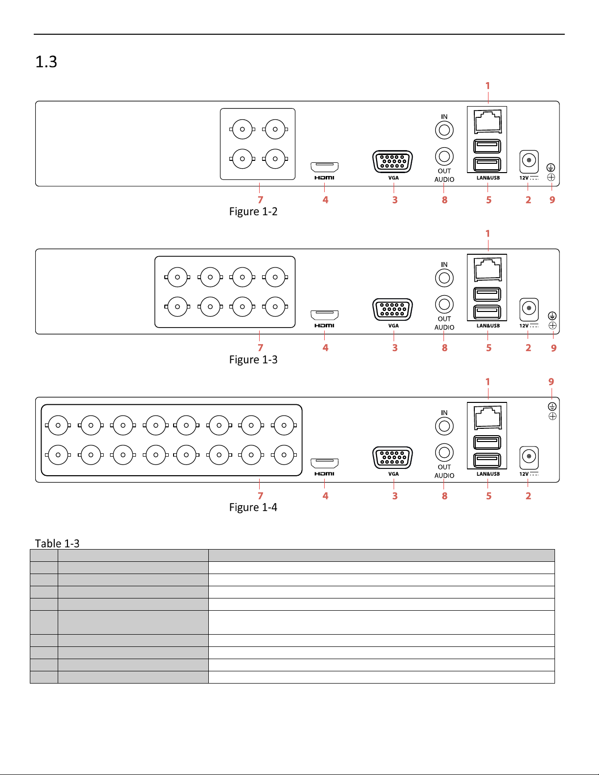
No.
Item
Description
1
LAN Network Interface
1 10 /100 /1000 Mbps self-adaptive Ethernet interface
2
Power Supply
12 VDC power supply
3
VGA Interface
DB9 connector for VGA output to display local video output and menu
4
HDMI Interface
HDMI video output connector
Universal Serial Bus (USB) ports for additional devices such as USB
mouse and USB Hard Disk Drive (HDD)
6
---
--- 7 Analog Camera Inputs
BNC connectors
8
Audio I/O
RCA connectors
9
Ground
Ground (needs to be connected when DVR starts up)
Rear Panels
ERT-204 Rear Panel
Description of Rear Panels
5 USB Interface
ERT-208 Rear Panel
ERT-216 Rear Panel
UM ERT-F2xxx 030118NA 12
Page 14
ERT-F2xxx DVR User Manual
Chapter 2 Getting Started
Device Startup and Activation
Starting Up and Shutting Down the DVR
Purpose:
Proper startup and shutdown procedures are crucial to expanding the life of the DVR.
Before You Start:
Check that the voltage of the extra power supply meets the DVR’s requirement, and the ground connection is
working properly.
Starting Up the DVR
Check the power supply is plugged into an electrical outlet. It is HIGHLY recommended that an
Uninterruptible Power Supply (UPS) be used in conjunction with the device. The Power indicator LED on
the front panel should be green, indicating the device is on.
The row of icons at the bottom of the screen shows the HDD status. “X” means that the HDD is not
installed or cannot be detected.
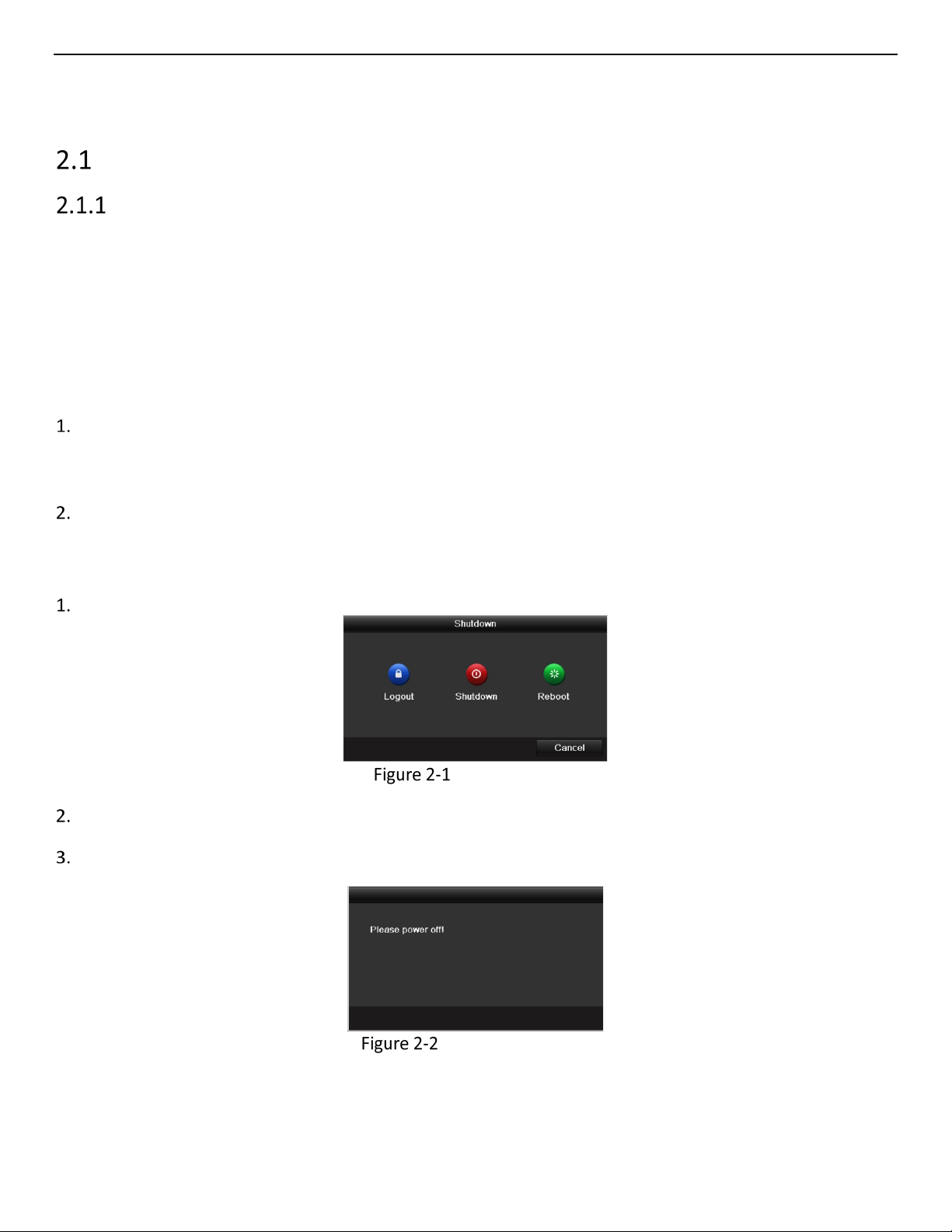
Shutting Down the DVR
Go to Menu > Shutdown.
Shutdown Menu
Click Shutdown.
Click Yes.
Shutdown Attention
UM ERT-F2xxx 030118NA 13
Page 15
ERT-F2xxx DVR User Manual
Rebooting the DVR
In the Shutdown menu, you can also reboot the DVR.
Go to Menu > Shutdown.
Click Logout to lock the DVR or Reboot to reboot the DVR.
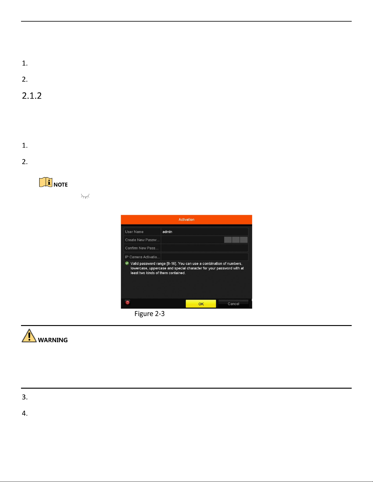
Activating Your Device
Purpose:
For the first-time access, you need to activate the device by setting an admin password. No operation is
allowed before activation.
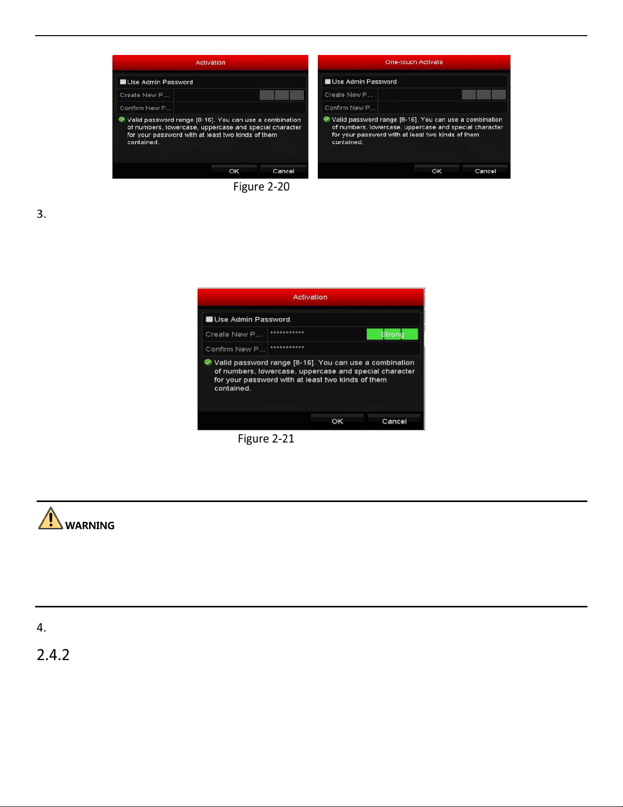
Input the same password in the text field of Create New Password and Confirm New Password.
Input a password in the IP Camera Activation field, to be used to activate connected IP cameras.
Click the icon to show the IP Camera Activation password as you input it to ensure that it is
input correctly.
Settings Admin Password
We highly recommend that you create a strong password of your own choosing (using a minimum of eight
characters, including at least three of the following categories: upper case letters, lower case letters, numbers,
and special characters) in order to increase the security of your product. We also recommend that you reset
your password regularly. Especially in a high security system, resetting the password monthly or weekly can
better protect your product.
Click OK to save the password and activate the device.
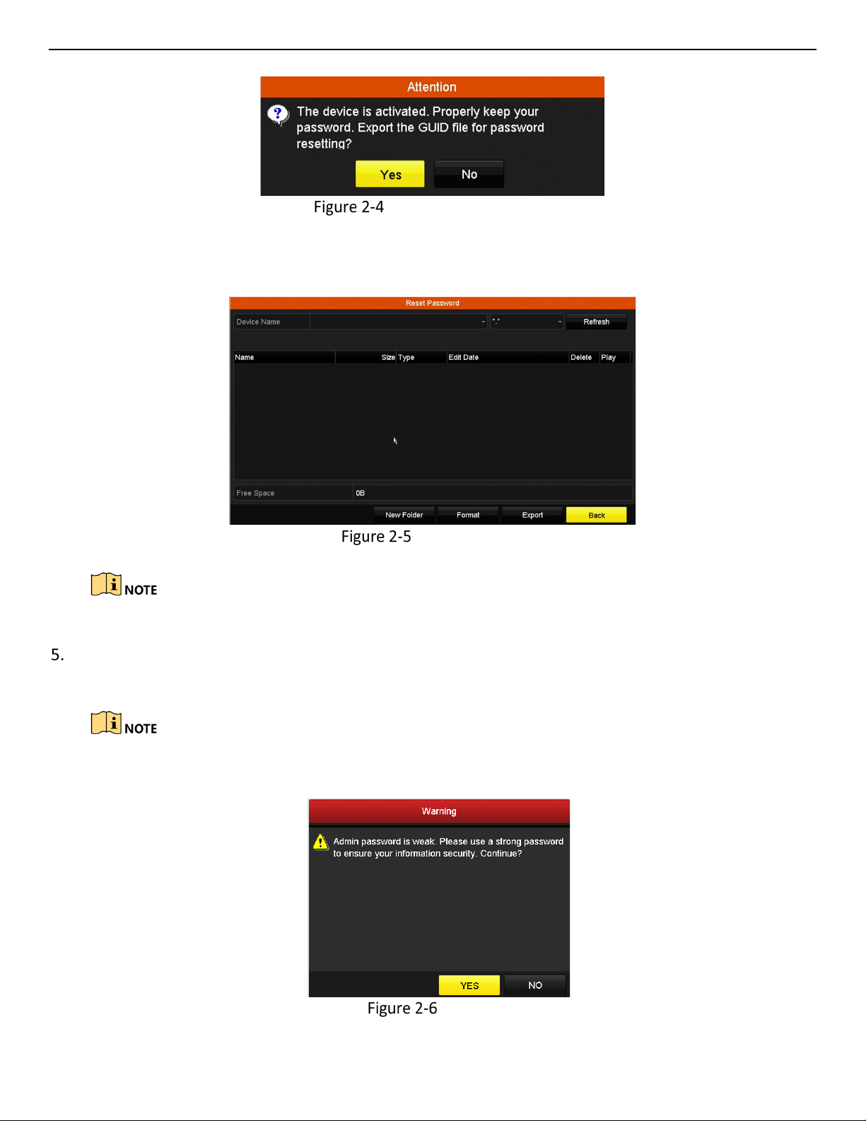
When the device is activated, the system pops up a message box to remind you to remember the
password. Slick Yes to continue to export the GUID file for the future password resetting.
UM ERT-F2xxx 030118NA 14
Page 16
ERT-F2xxx DVR User Manual
Export GUID File Remind
Insert the flash drive into your device, and export the GUID file to the flash drive in the Reset Password
interface.
Export GUID File
Keep your GUID file safely for future password resetting.
When the device is activated, the system pops up a message box to remind you to remember the
password.
For an old version device updated to the new version, the following dialog box will pop up once the
device starts up. Click YES and follow the wizard to set a strong password.
Warning
UM ERT-F2xxx 030118NA 15
Page 17
ERT-F2xxx DVR User Manual
Using the Unlock Pattern for Login
Configure the unlock pattern for device login.
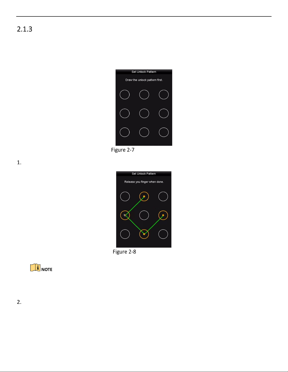
Configuring the Unlock Pattern
After the device is activated, configure the device unlock pattern.
Set Unlock Pattern
Use the mouse to draw a pattern among the nine dots on the screen. Release the mouse when done.
Draw the Pattern
Connect at least four dots to draw the pattern.
Each dot can be connected only once.
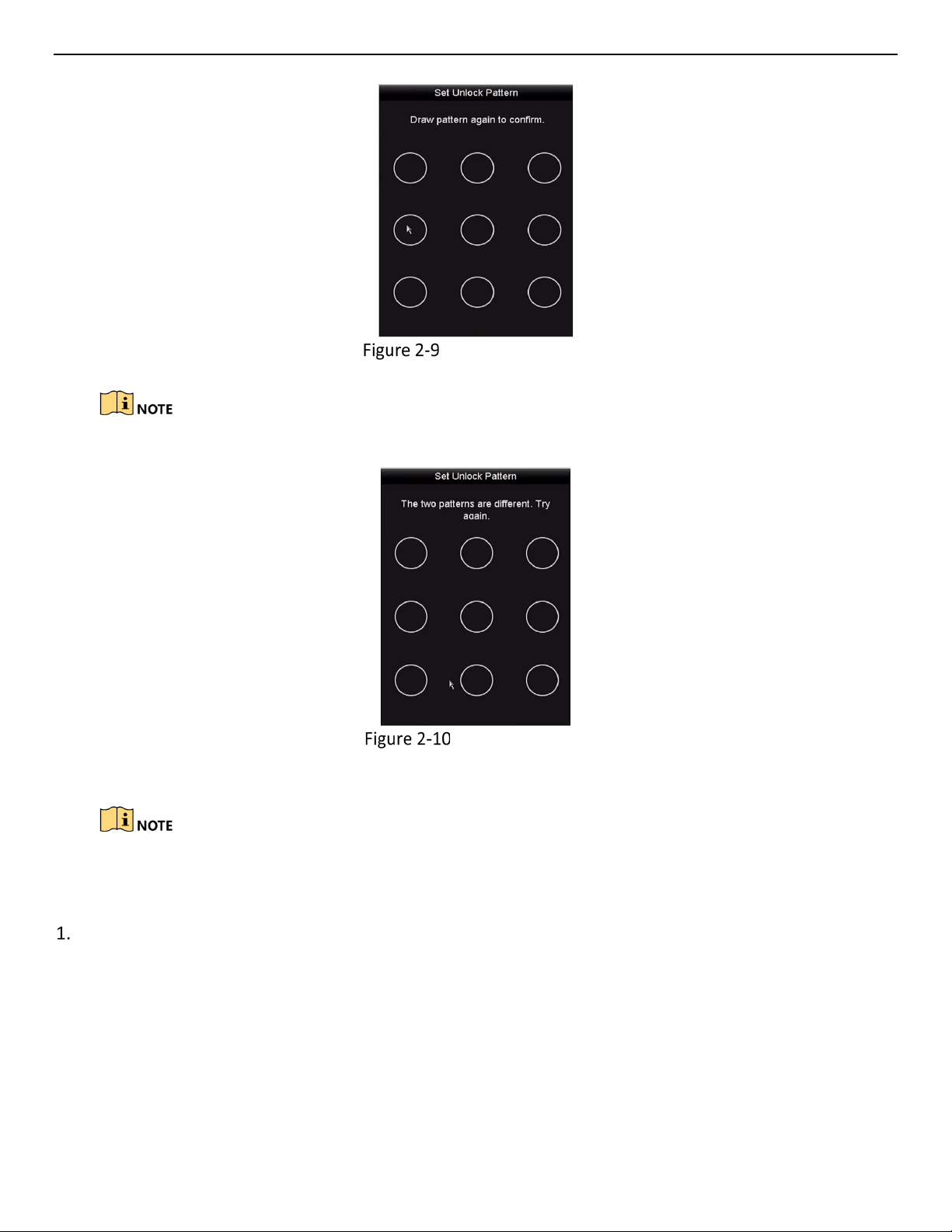
Draw the same pattern again to confirm it. When the two patterns match, the pattern is configured
successfully.
UM ERT-F2xxx 030118NA 16
Page 18
ERT-F2xxx DVR User Manual
If the two patterns are different, you must set the pattern again.
Confirm the Pattern
Re-set the Pattern
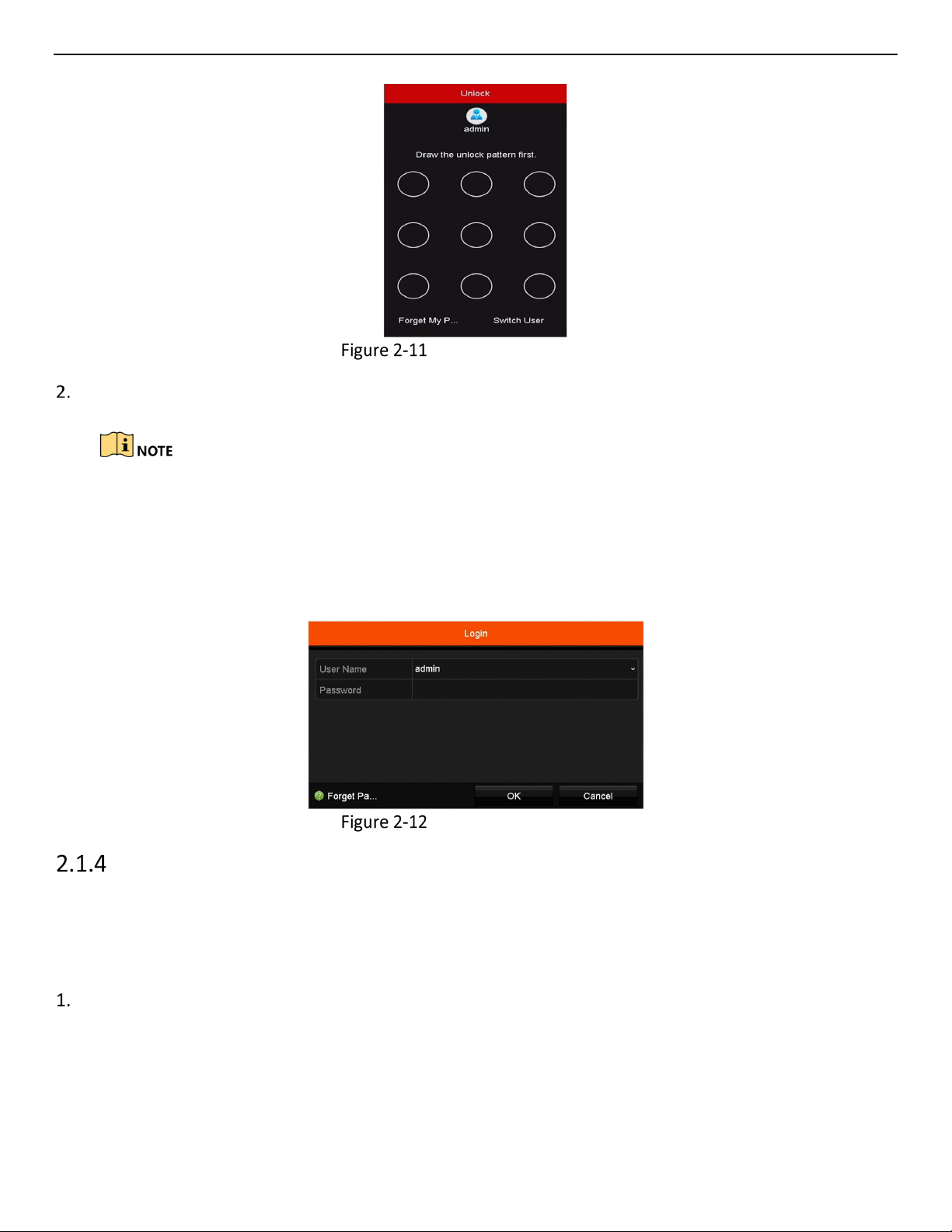
Logging in via Unlock Pattern
Only the admin user has the permission to unlock the device.
Configure the pattern first before unlocking. Refer to Configuring the Unlock Pattern.
Right click the mouse on the screen and select the menu to enter the interface as shown in Figure 2.8.
UM ERT-F2xxx 030118NA 17
Page 19
ERT-F2xxx DVR User Manual
Draw the Unlock Pattern
Draw the pre-defined pattern to unlock to enter the menu operation.
If you forget your pattern, select the Forgot My Pattern or Switch User option to enter the normal
login dialog box.
If the pattern you draw is different from the pattern you configured, try again.
If you draw the wrong pattern more than five times, the system will switch to the normal login
mode automatically.
Normal Login Dialog Box
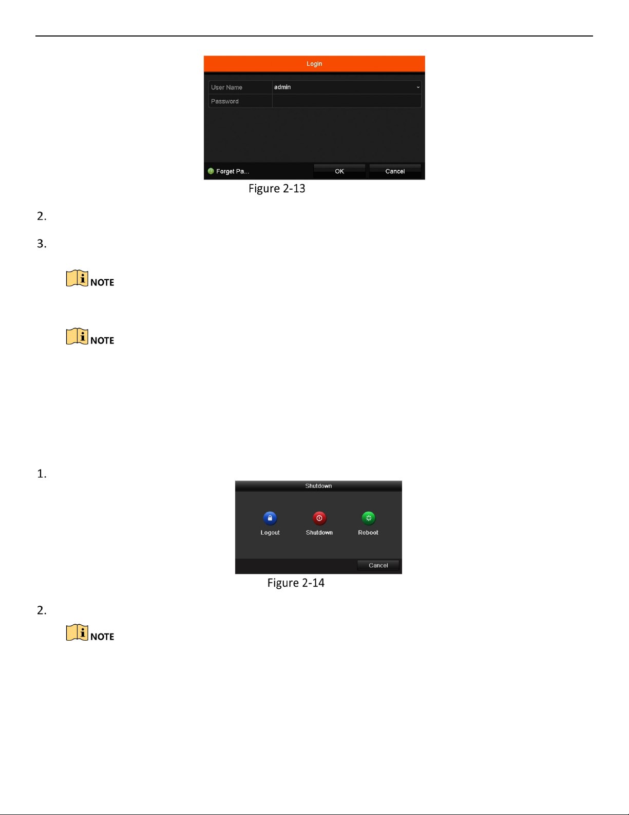
Login and Logout
User Login
Purpose:
If the DVR logs out, you must log in to the device before operating the menu and other functions.
Select User Name in the drop-down list.
UM ERT-F2xxx 030118NA 18
Page 20
ERT-F2xxx DVR User Manual
Input password.
Click OK to log in.
If you forget the admin password, click Forgot Password to reset the password.
Login Interface
The device locks for 60 seconds if the admin user performs seven failed password attempts (five
attempts for the guest/operator).
User Logout
Purpose:
After logging out, the monitor turns to live view mode. To perform operations, enter your user name and
password to log in again.
Go to Menu > Shutdown.
Logout
Click Logout.
After you log out of the system, menu operation on the screen is invalid. You are required to input a
user name and password to unlock the system.
UM ERT-F2xxx 030118NA 19
Page 21
ERT-F2xxx DVR User Manual
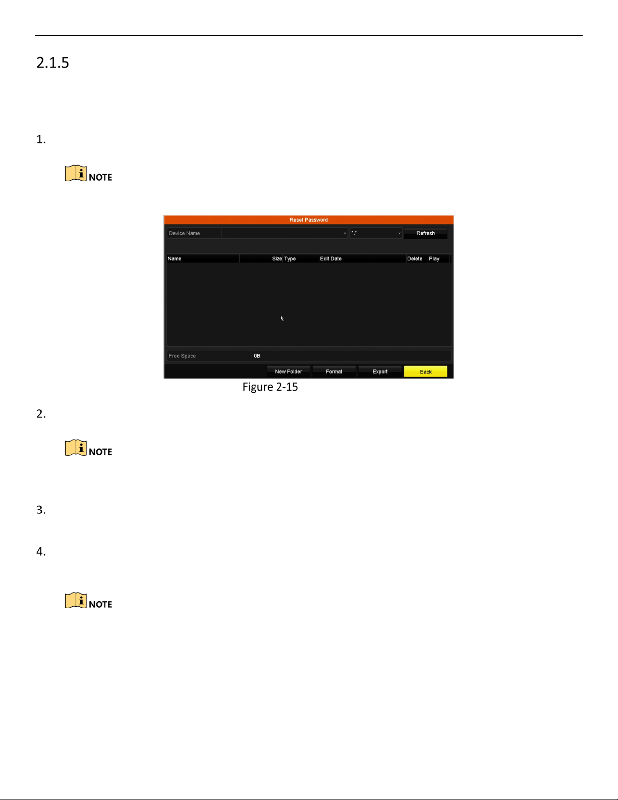
Resetting Your Password
If you forget the admin password, you can reset the password by importing the GUID file. The GUID file must
be exported and saved in the local flash drive after you have activated the device (refer to Chapter 2.1.2
Activating Your Device).
On the user login interface, click Forgot Password to enter the Reset Password interface.
Insert the flash drive containing the GUID file into the DVR before resetting the password.
Reset Password
Select the GUID file from the USB flash drive and click Import to import the file to the device.
If you import the wrong GUID file seven times, you will be not allowed to reset the password for 30
minutes.
After the GUID file is successfully imported, enter the reset password interface to set the new admin
password.
Click OK to set the new password. You can export the new GUID file to the USB flash drive for future
password resetting.
When the new password is set, the original GUID file will be invalid. The new GUID file should be
exported for future password resetting. You can also enter the User > User Management interface
to edit the admin user and export the GUID file.
UM ERT-F2xxx 030118NA 20
Page 22
ERT-F2xxx DVR User Manual
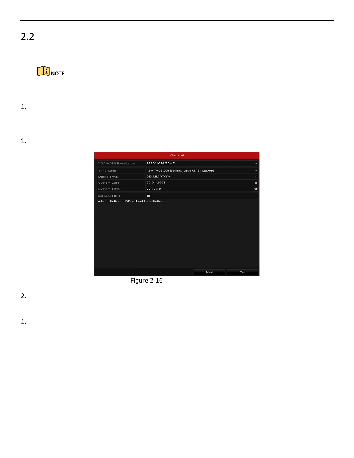
Using the Setup Wizard for Basic Configuration
The Setup Wizard can guide you to configure the system resolution, system date/time, HDD initialization, IP
camera management, etc.
To cancel the Setup Wizard, click Exit. You can choose to use the Setup Wizard next time by leaving
the “Start wizard when the device starts?” checkbox checked.
Enter the general settings interface to configure the VGA/HDMI resolution, system date and time, and
HDD initialization.
Initialize HDD
Check to initialize a new HDD used for the first time (factory-installed HDDs are already initialized).
Start Wizard Interface
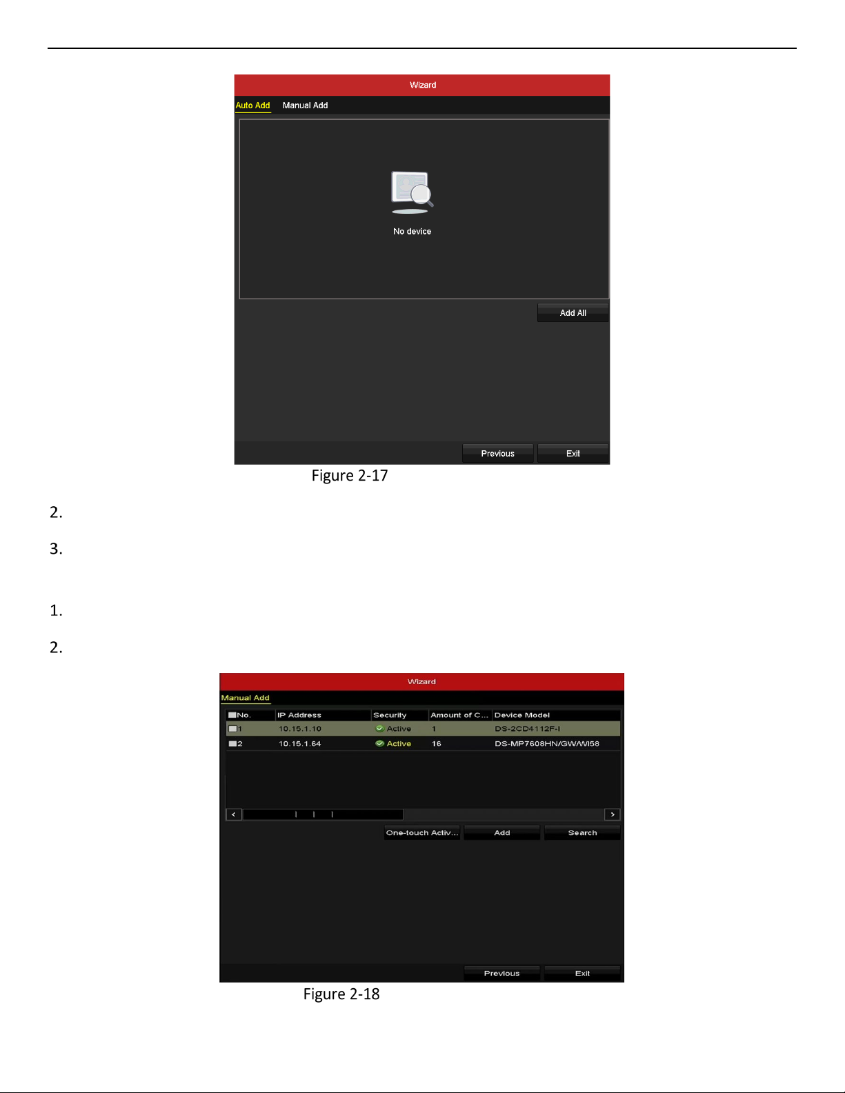
Click Next to enter the IP Camera Management interface.
Automatically Add Cameras
You can quickly add one or more IP cameras that are searched within the same network and have the
same user name and password with the device.
UM ERT-F2xxx 030118NA 21
Page 23
ERT-F2xxx DVR User Manual
Start Wizard Interface
Click Add All. The device starts to search and add the matched cameras automatically.
Click OK when the cameras are added.
Manually Add Cameras
Click Search to search for online IP cameras within the same network.
Click Add to add the cameras that have the same user name and password as the device.
IP Camera Management
UM ERT-F2xxx 030118NA 22
Page 24
ERT-F2xxx DVR User Manual
Before adding a camera, make sure the IP camera to be added is in active status. If the camera is in
inactive status, click the inactive icon of the camera to set the password to activate it. You can also
select multiple cameras from the list and click One-touch Activate to activate the cameras in batch.
Click Exit to complete the Setup Wizard.
Adding and Enabling Analog Cameras
Connect analog camera(s) to the “Video In” BNC connectors. Analog cameras are enabled by default; no
further action is required.
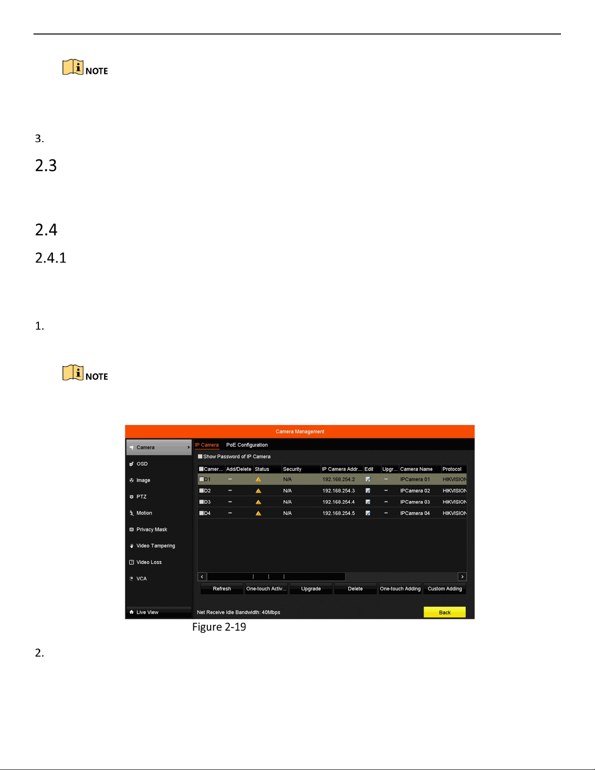
Adding and Connecting IP Cameras
Activating IP Cameras
Purpose:
Before adding the camera, make sure the IP camera to be added is in active status.
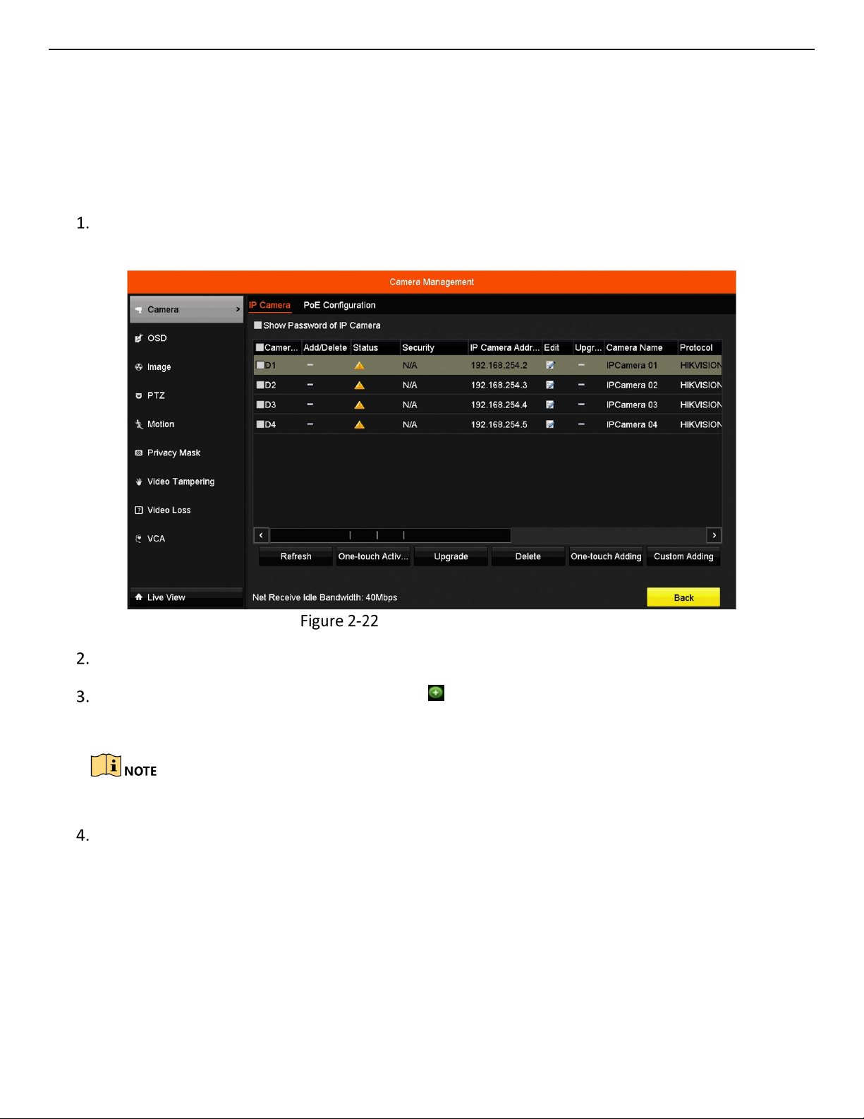
Select Add IP Camera from the right-click menu in live view mode or Go to Menu > Camera > Camera to
enter the IP camera management interface.
For detected online IP cameras in the same network segment, the Password status shows whether
it is active or inactive.
IP Camera Management Interface
Click the inactive icon of the camera to enter the following interface to activate it. You can also select
multiple cameras from the list and click One-touch Activate to activate the cameras in batch.
UM ERT-F2xxx 030118NA 23
Page 25
ERT-F2xxx DVR User Manual
Set the camera password to activate it.
• Use Admin Password
If you check the checkbox, the camera(s) will be configured with the same admin password as the
operating DVR.
Activate the Camera
Set New Password
• Create New Password
If the admin password is not used, you must create the new password for the camera and confirm it.
We highly recommend you create a strong password of your own choosing (using a minimum of eight
characters, including at least three of the following categories: upper case letters, lower case letters, numbers,
and special characters) in order to increase the security of your product. We also recommend that you reset
your password regularly. Especially in high security systems, resetting the password monthly or weekly can
better protect your product.
Click OK to finish activating the IP camera. The camera security status will change to Active.
Adding Online IP Cameras
Purpose:
One function of the DVR is to connect the network cameras and record video. Before you can get a live view or
record of the video, add the network cameras to the connection list of the device.
UM ERT-F2xxx 030118NA 24
Page 26
ERT-F2xxx DVR User Manual
Before You Start:
Ensure the network connection is valid and correct. For detailed checking and configuring of the network, see
Chapter Checking Network Traffic and Chapter Configuring Network Detection.
Adding IP Cameras
OPTION 1
Select Add IP Camera from the right-click menu in live view mode or go to Menu > Camera> Camera to
enter the IP camera management interface.
Adding IP Camera Interface
Online cameras in the same network segment will be detected and displayed in the camera list.
Select the IP camera from the list and click the button to add the camera, or you can click
One-touch Adding to add all cameras (with the same login password) from the list.
Make sure the camera to add has already been activated.
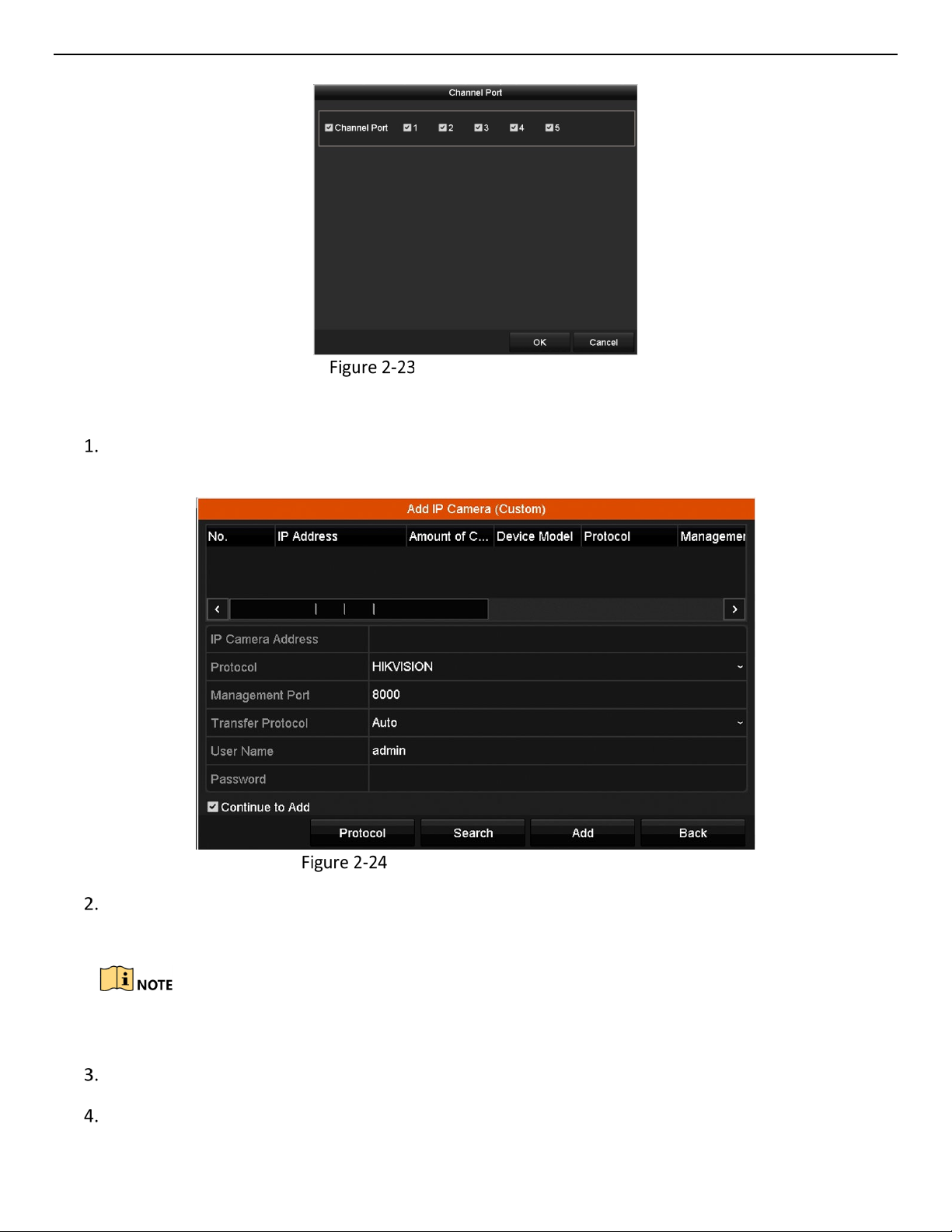
Check the Channel Port checkbox in the pop-up window, as shown in the following figure, and click OK
to add multiple channels.
UM ERT-F2xxx 030118NA 25
Page 27
ERT-F2xxx DVR User Manual
Selecting Multiple Channels
OPTION 2
On the IP Camera Management interface, click Custom Adding to pop up the Add IP Camera (Custom)
interface.
Custom Adding IP Camera Interface
You can edit the IP address, protocol, management port, and other information of the IP camera to be
added.
If the IP camera to add has not been activated, activate it from the IP camera list on the camera
management interface.
(Optional) Check Continue to Add to add other IP cameras.
Click Add to add the camera. Successfully added cameras are listed in the interface.
UM ERT-F2xxx 030118NA 26
Page 28
ERT-F2xxx DVR User Manual
Icon
Explanation
Icon
Explanation
Camera disconnected; click icon to get
!
Refer to the following table for the description of the icons
Description of Icons
Edit basic camera parameters
camera’s exception information
Play connected camera’s live video
Upgrade the connected camera
Delete the IP camera
Camera connected
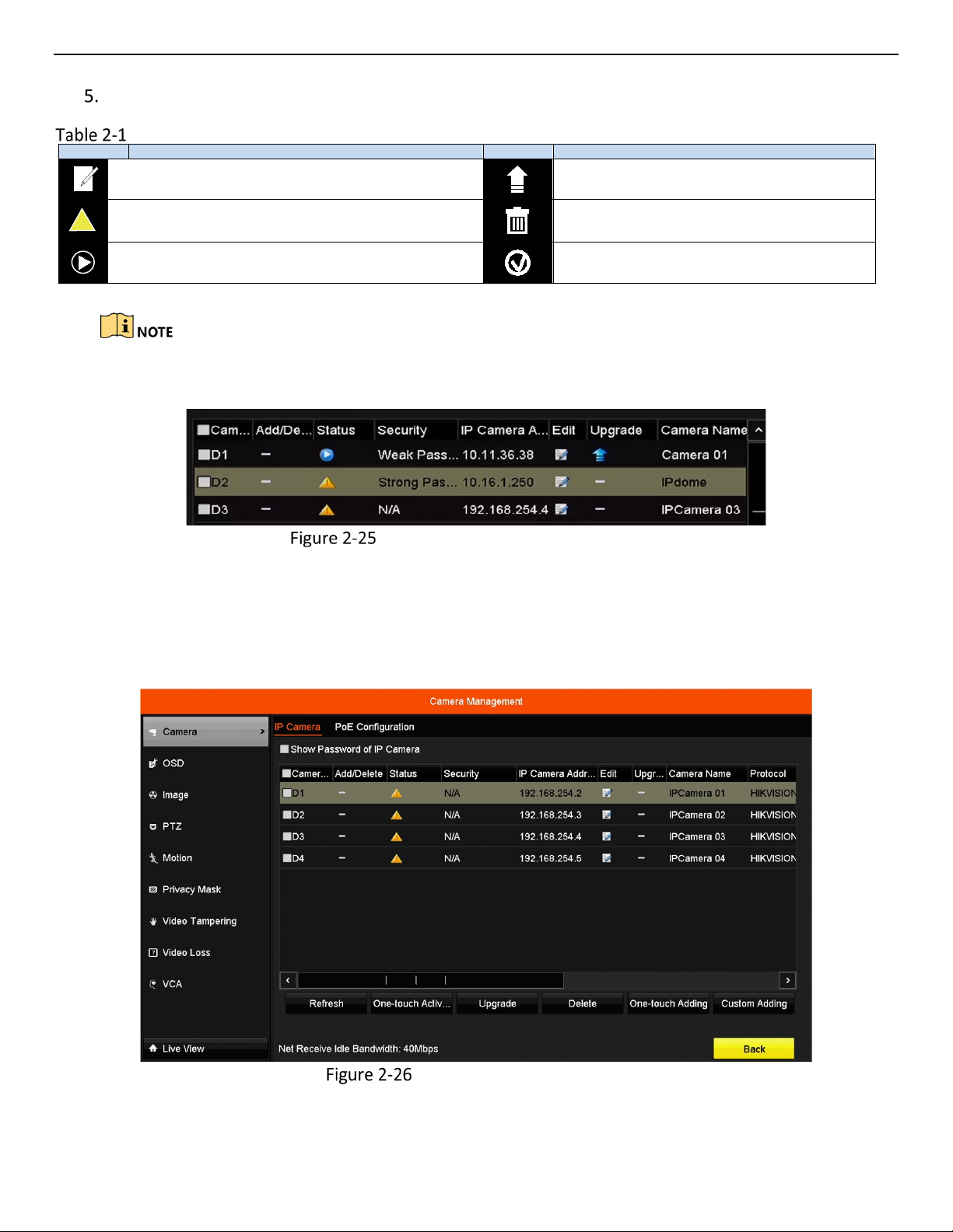
For the added IP cameras, the Security status shows the security level of the password of camera:
strong password, weak password and risk password.
Security Level of IP Camera’s Password
Showing the IP Camera Password
For the admin login user account, you can check Show Password of IP Camera to make the successfully added
IP cameras’ passwords visible.
You must enter the admin password to confirm permission.
Show Password of IP Camera
UM ERT-F2xxx 030118NA 27
Page 29
ERT-F2xxx DVR User Manual
The linked image cannot be displayed. The file may have been moved, renamed, or deleted. Verify that the link points to the correct file and location.
Editing the Connected IP Cameras and Configuring Customized Protocols
After adding IP cameras, the basic camera information is listed. You can configure the basic IP camera settings.
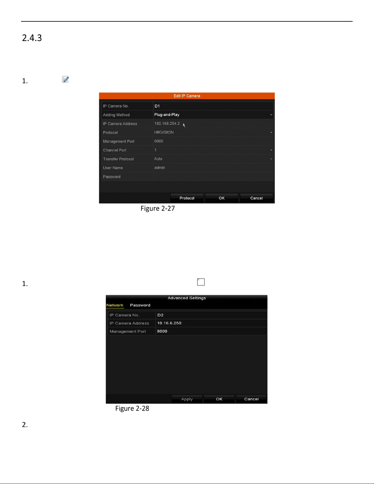
Editing the IP Camera Parameters
Click the icon to edit the parameters; you can edit the IP address, protocol, and other parameters.
Edit the Parameters
• Channel Port
1. If the connected device is an encoding device with multiple channels, you can choose the channel
to connect by selecting the channel port no. in the drop-down list.
2. Click OK to save the settings and exit the editing interface.
Editing the Advanced Parameters
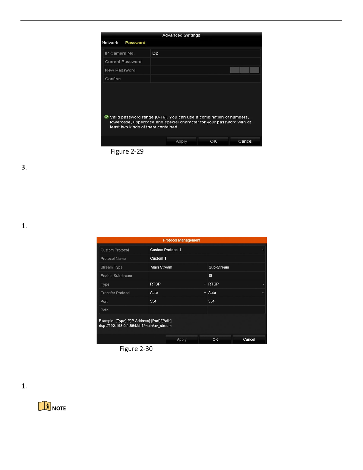
Drag the horizontal scroll bar to the right and click the icon.
Network Configuration of the Camera
You can edit the network information and the camera password.
UM ERT-F2xxx 030118NA 28
Page 30
ERT-F2xxx DVR User Manual
Password Configuration of the Camera
Click OK to save the settings and exit the interface.
Configuring the Customized Protocols
Purpose:
To connect network cameras that are not configured with standard protocols, you can configure the
customized protocols.
Click Protocol in the custom adding IP camera interface to enter the protocol management interface.
Protocol Management Interface
There are 16 customized protocols provided in the system, you can edit the protocol name and choose
whether to enable the sub-stream.
Choose the protocol type of transmission and choose the transfer protocols.
Before customizing the protocol for the network camera, contact the network camera manufacturer
to consult the URL (uniform resource locator) for getting the main stream and sub-stream.
UM ERT-F2xxx 030118NA 29
Page 31

ERT-F2xxx DVR User Manual
The format of the URL is: [Type]://[IP Address of the network camera]:[Port]/[Path].
Example: rtsp://192.168.1.55:554/ch1/main/av_stream.
• Protocol Name: Edit the name for the custom protocol.
• Enable Substream: If the network camera does not support sub-stream or the sub-stream is not
needed leave the checkbox empty.
• Type: The network camera adopting custom protocol must support streaming through standard RT S P.
• Transfer Protocol: Select the transfer protocol for the custom protocol.
• Port: Set the port no. for the custom protocol.
• Path: Set the resource path for the custom protocol. E.g., ch1/main/av_stream.
The protocol type and the transfer protocols must be supported by the connected network camera.
After adding the customized protocols, the protocol name is listed in the drop-down protocol list.
Protocol Setting
Choose the protocols you just added to validate the connection of the network camera.
Enabling ONVIF
Purpose:
To interface to third-party software that conforms to the ONVIF protocol, you must enable ONVIF on the NVR.
Go to Menu > System Service > ONVIF.
Check the Enable ONVIF checkbox.
Click Apply.
Reboot the system.
UM ERT-F2xxx 030118NA 30
Page 32

ERT-F2xxx DVR User Manual
Icons
Description
ONVIF Checkbox
Chapter 3 Live View
Live View displays the video image getting from each camera in real time.
Live View Status Icons
In live view mode, there are status icons at the upper-right of the screen for each channel, showing the status
of the record and alarm in the channel, so that you can know whether the channel is recorded, or whether
there are alarms occur as soon as possible.
Description of Live View Icons
Alarm (video loss, video tampering, motion detection, sensor alarm, or VCA alarm)
Record (manual record, continuous record, motion detection, sensor alarm, or
VCA alarm triggered record)
Alarm & Record
Event/Exception (motion detection, sensor alarm, VCA alarm, or exception
information appears at the lower-left corner of the screen. Refer to Chapter 8.8
Setting Alarm Response Actions for details.)
Operations in Live View Mode
In live view mode, there are many functions provided. The functions are listed below.
When the aux output is enabled, the main output cannot perform any operation, and you can do some basic
operation on the live view mode for the Aux output.
UM ERT-F2xxx 030118NA 31
Right-Click Menu
Page 33

ERT-F2xxx DVR User Manual
Name
Description
Common Menu
Quick access to the sub-menus that you frequently visit.
Menu
Enter the main menu of the system by right clicking the mouse.
Single Screen
Switch to the single full screen by choosing channel number from the drop-down list.
Multi-screen
Adjust the screen layout by choosing from the drop-down list.
Previous Screen
Switch to the previous screen.
Next Screen
Switch to the next screen.
Start/Stop
Auto-switch
Start Recording
Start continuous recording or motion detection recording of all channels.
Add IP Camera
Enter the IP Camera Management interface, and manage the cameras.
Enter the playback interface and start playing back the video of the selected channel
immediately.
Output Mode
Four modes of output supported, including Standard, Bright, Gentle, and Vivid.
The DVR checks the connection of the output interfaces to define the main and
the VGA is used as the aux output.
Icon
Description
Icon
Description
Icon
Description
/
Enable/Disable
Manual Record
/
Mouse Operation in Live View
Playback
Aux Monitor
Enable/disable the auto-switch of the screens.
auxiliary output interfaces. The priority level for the main and aux output is HDMI >
VGA.
When both the HDMI and VGA are connected, the HDMI is used as main output and
The dwell time of the live view configuration must be set before using Start Auto-switch.
The right-click menu varies by model. Please refer to the actual GUI menu of the device.
Quick Setting Toolbar in Live View Mode
On each channel’s screen, single click the mouse in the corresponding screen to display a quick setting toolbar.
Quick Setting Toolbar
Description of Quick Setting Toolbar Icons
PTZ Control
Face Detection
Instant Playback
Digital Zoom
Live View Strategy
Mute/Audio on
Image Settings
Information
Close
Instant Playback shows only the record in the last five minutes. If no record is found, it means there is no
record during the last five minutes.
Digital Zoom zooms in the live image. You can zoom in the image to different proportions (1 to 16x) by
moving the sliding bar from to . You can also scroll the mouse wheel to control the zoom in/out.
UM ERT-F2xxx 030118NA 32
Main/Sub-Stream
Page 34

ERT-F2xxx DVR User Manual
Digital Zoom
Image Settings icon can be selected to enter the Image Settings menu. You can set the image parameters
such as brightness, contrast, saturation, and hue.
Image Settings – Customize
Live View Strategy can be selected to set strategy, including Real-time, Balanced, and Fluency.
Live View Strategy
Move the mouse onto the icon to show the real-time stream information, including the frame rate,
bitrate, resolution, and stream type.
UM ERT-F2xxx 030118NA 33
Page 35

ERT-F2xxx DVR User Manual
Information
Adjusting Live View Settings
Purpose:
Live View settings can be customized according to different needs. You can configure the output interface,
dwell time for screen to be shown, mute or turning on the audio, the screen number for each channel, etc.
Go to Menu > Configuration > Live View.
Live View-General
The settings available in this menu include:
• Video Output Interface: Designates the output for which to configure the settings. Only VGA/ HDMITM
is selectable by default.
• Live View Mode: Designates the display mode to be used for Live View.
• Dwell Time: The time in seconds to dwell between switching of channels when enabling auto-switch in
Live View.
• Enable Audio Output: Enables/disables audio output for the selected video output.
• Volume: Adjust the volume of live view, playback and two-way audio for the selected output interface.
• Event Output: Designates the output to show event video.
UM ERT-F2xxx 030118NA 34
Page 36

ERT-F2xxx DVR User Manual
• Full Screen Monitoring Dwell Time: The time in seconds to show alarm event screen.
Set camera order.
Live View Camera Order
• Select a View mode in . Up to 36-screen display is supported for 32-ch DVR.
• Select the small window, and double-click on the channel number to display the channel on the
window.
• If you do not want the camera to be displayed on the live view interface, click the corresponding to
stop it.
• You can also click the icon to start live view for all the channels and click to stop all live views.
• Click Apply to save the settings.
Set the stream type for the camera’s live view.
• Click More Settings to enter the more settings interface.
• Select the camera to configure from the list.
• Set the stream type to Main Stream, Sub-Stream, or Auto.
UM ERT-F2xxx 030118NA 35
Page 37

ERT-F2xxx DVR User Manual
• Click Apply to save the settings.
Stream Type Settings
• (Optional) Click Copy to copy the stream type settings of the current camera to other camera(s).
UM ERT-F2xxx 030118NA 36
Page 38

ERT-F2xxx DVR User Manual
Chapter 4 PTZ Controls
Configuring PTZ Settings
Purpose:
Follow the procedure to set the PTZ parameters. Configure the PTZ parameters before controlling the PTZ
camera.
Go to Menu > Camera > PTZ.
Click PTZ Parameters to set the PTZ parameters.
PTZ Settings
PTZ- General
UM ERT-F2xxx 030118NA 37
Page 39

ERT-F2xxx DVR User Manual
Choose the camera for PTZ setting in the Camera drop-down list.
Enter the PTZ camera parameters.
All the parameters should be exactly the same as the PTZ camera parameters.
Click Apply to save the settings.
Setting PTZ Presets, Patrols, and Patterns
Before You Start:
Make sure that the presets, patrols, and patterns are supported by the PTZ protocols.
Customizing Presets
Purpose:
Follow the steps to set the Preset location you want the PTZ camera to point to when an event takes place.
Go to Menu > Camera > PTZ.
PTZ Settings
Use the directional button to wheel the camera to the location where you want to set the preset. Zoom
and focus operations can be recorded in the preset as well.
Enter the preset no. (1 to 255) in the preset text field.
Click Set to link the location to the preset.
Repeat steps 2-3 to save more presets.
Click Clear to clear the location information of the preset, or click Clear All to clear the location
information of all the presets.
UM ERT-F2xxx 030118NA 38
Page 40

ERT-F2xxx DVR User Manual
Calling Presets
Purpose:
This feature enables the camera to point to a specified position such as a window when an event takes place.
Click the PTZ button in the lower-right corner of the PTZ setting interface, or press the PTZ button on the
front panel, or click the PTZ Control icon in the quick setting bar, or select the PTZ option in the
right-click menu to show the PTZ control panel.
Choose Camera in the drop-down list.
Click the button to show the general settings of the PTZ control.
PTZ Panel - General
Click to enter the preset no. in the corresponding text field.
Click Call Preset to call it.
Customizing Patrols
Purpose:
Patrols can be set to move the PTZ to different key points and have it stay there for a set duration before
moving on to the next key point. The key points correspond to the presets. The presets can be set following
the steps above in Customizing Presets.
Go to Menu > Camera > PTZ.
UM ERT-F2xxx 030118NA 39
Page 41

ERT-F2xxx DVR User Manual
Select patrol no. in the drop-down patrol list.
Click Set to add key points for the patrol.
PTZ Settings
Key point Configuration
Configure key point parameters such as the key point no., duration to stay at one key point, and patrol
speed. The key point corresponds to the preset. Key Point No. determines the order the PTZ will follow
while cycling through the patrol. Duration refers to the time span to stay at the corresponding key point.
Speed defines the speed the PTZ will move from one key point to the next.
Click Add to add the next key point to the patrol. Click OK to save the key point to the patrol.
To delete all the key points, click Clear for the selected patrol, or click Clear All to delete all the key points
for all patrols.
Calling Patrols
Purpose:
Calling a patrol moves the PTZ according the predefined patrol path.
Click the PTZ button in the lower-right corner of the PTZ setting interface, or press the PTZ button on the
front panel, or click the PTZ Control icon in the quick setting bar, or select the PTZ option in the
right-click menu to show the PTZ control panel.
UM ERT-F2xxx 030118NA 40
Page 42

ERT-F2xxx DVR User Manual
Click the button to show the general settings of the PTZ control.
PTZ Panel - General
Select a patrol in the drop-down list and click Call Patrol to call it.
You can click Stop Patrol to stop calling it.
Customizing Patterns
Purpose:
Patterns can be set by recording the PTZ movement. Call the pattern to make the PTZ move according to the
predefined path.
Go to Menu > Camera > PTZ.
PTZ Settings
Choose pattern number in the drop-down list.
Click Start and click corresponding buttons in the control panel to move the PTZ camera, and click Stop to
stop it. The PTZ movement is recorded as the pattern.
UM ERT-F2xxx 030118NA 41
Page 43

ERT-F2xxx DVR User Manual
Calling Patterns
Purpose:
Follow the procedure to move the PTZ camera according to the predefined patterns.
Click PTZ in the lower-right corner of the PTZ setting interface, or press the PTZ button on the front panel,
or click the PTZ Control icon in the quick setting bar, or select the PTZ option in the right-click menu
to show the PTZ control panel.
Click the button to show the general settings of the PTZ control.
PTZ Panel - General
Click Call Pattern to call it.
Click Stop Pattern to stop calling it.
Customizing Linear Scan Limit
Purpose:
Linear Scan can be enabled to trigger a horizantal direction scan in the predefined range.
Go to Menu > Camera > PTZ.
PTZ Settings
UM ERT-F2xxx 030118NA 42
Page 44

ERT-F2xxx DVR User Manual
Use the directional button to wheel the camera to the location you want to set as the limit, and click the
Left Limit or Right Limit button to link the location to the corresponding limit.
The speed dome starts linear scan from the left limit to the right limit, and you must set the left limit
on the left side of the right limit, as well the angle from the left limit to the right limit should be no
more than 180°.
Calling Linear Scan
Before operating this function, make sure the connected camera supports linear scan and is in
HIKVISION protocol.
Purpose:
Follow the procedure to call the linear scan in the predefined scan range.
Click PTZ in the lower-right corner of the PTZ setting interface, or press the PTZ button on the front panel,
or click the PTZ Control icon in the quick setting bar to enter the PTZ setting menu in live view mode.
Click the button to show the one-touch function of the PTZ control.
PTZ Panel - One-touch
Click Linear Scan to start the linear scan and click Linear Scan again to stop it.
You can click Restore to clear the defined left limit and right limit data, and the dome needs to reboot to
make settings take effect.
One-Touch Park
Before operating this function, make sure the connected camera supports linear scan and is in
HIKVISION protocol.
UM ERT-F2xxx 030118NA 43
Page 45

ERT-F2xxx DVR User Manual
Purpose:
Certain speed domes can be configured to start a predefined park action (scan, preset, patrol, etc.)
automatically after a period of inactivity (park time).
Click PTZ in the lower-right corner of the PTZ setting interface, or press the PTZ button on the front panel,
or click the PTZ Control icon in the quick setting bar to enter the PTZ setting menu in live view mode.
Click the button to show the one-touch function of the PTZ control.
PTZ Panel - One-touch
There are three one-touch park types selectable. Click the corresponding button to activate the park
action.
• Park (Quick Patrol): The dome starts patrol from predefined preset 1 to preset 32 in order after the
park time. Undefined presets will be skipped.
• Park (Patrol 1): The dome starts move according to predefined patrol 1 path after the park time.
• Park (Preset 1): The dome moves to the predefined preset 1 location after the park time.
The park time can be set only through the speed dome configuration interface. Default value is 5s.
Click the button again to deactivate it.
PTZ Control Panel
To enter the PTZ control panel, there are two ways supported.
OPTION 1
In the PTZ settings interface, click PTZ on the lower-right corner, next to the Back button.
OPTION 2
In Live View mode, press the PTZ Control button on the front panel or on the remote control, or choose
the PTZ Control icon , or select the PTZ option in the right-click menu.
Click Configuration on the control panel to enter the PTZ Settings interface.
UM ERT-F2xxx 030118NA 44
Page 46

ERT-F2xxx DVR User Manual
Icon
Description
Icon
Description
Icon
Description
Direction button
button
The speed of the
PTZ movement
Image
Centralization
Switch to the
interface
Switch to the
interface
Start pattern/
patrol
Stop the
movement
In PTZ control mode, the PTZ panel will be displayed when a mouse is connected to the device. If no
mouse is connected, the icon appears in the lower-left corner of the window, indicating that
this camera is in PTZ control mode.
Description of the PTZ panel icons
PTZ Panel
and auto-cycle
3D-Zoom
Switch to the PTZ
control interface
Previous item
patrol/pattern
Zoom+, Focus+,
Iris+
Light on/off
one-touch control
Next item
Exit
Zoom-, Focus-,
Iris-
Wiper on/off
Menu
general settings
Minimize windows
UM ERT-F2xxx 030118NA 45
Page 47

ERT-F2xxx DVR User Manual
Chapter 5 Recording Settings
Configuring Parameters
Purpose:
By configuring the parameters you can define the parameters that affect the image quality such as
transmission stream type, resolution, etc.
Before You Start:
Make sure that an HDD has been installed. If not, install and initialize an HDD (Menu > HDD > General).
HDD- General
Check the storage HDD mode.
• Click Advanced to check the HDD storage mode.
• If the HDD mode is Quota, set the maximum record capacity. For detailed information, see Chapter
10.2 Configuring Quota Mode.
Go to Menu > Record > Parameters.
UM ERT-F2xxx 030118NA 46
Page 48

ERT-F2xxx DVR User Manual
Recording Parameters
Set recording parameters.
• Select Record to configure. You can configure the stream type, the resolution, and other parameters
on your demand.
• Enable H.264+ Mode: Check the checkbox to enable this mode. Once enabled, the Max. Bitrate Mode,
Max. Bitrate (Kbps), and Max. Bitrate Range Recommend are not configurable. Enabling it helps to
ensure high video quality with a lowered bitrate.
The function is available only for IP cameras that support a H.264+ stream.
• Click More Settings to set advanced recording parameters, and then click OK to finish editing.
Recording Parameters-More Settings
• Pre-Record: The time set to record before the scheduled time or event. For example, if an alarm
triggers the recording at 10:00, if you set the pre-record time to 5 seconds, the camera records it at
9:59:55.
UM ERT-F2xxx 030118NA 47
Page 49

ERT-F2xxx DVR User Manual
• Post-Record: The time you set to record after the event or the scheduled time. For example, when an
alarm triggered recording ends at 11:00, if you set the post-record time as 5 seconds, it records till
11:00:05.
• Expired Time: The expired time is the longest time for a record file to be kept in the HDD, if the
deadline is reached, the file will be deleted. You can set the expired time to 0, and then the file will not
be deleted. The actual keeping time for the file should be determined by the capacity of the HDD..
• Record Audio: Check the checkbox to enable or disable audio recording.
• Video Stream: Main stream and sub-stream are selectable for recording. When you select sub-stream,
you can record for a longer time with the same storage space.
• Click Apply to save the settings.
You can enable the ANR (Automatic Network Replenishment) function via the Web browser
(Configuration > Storage > Schedule Settings > Advanced) to save the video files in the IP camera
when the network is disconnected, and synchronize the files to the DVR when the network is
resumed.
The parameters of Main Stream (Event) are read-only.
• Parameter Settings for Sub-stream
• Enter the Sub-stream tab page.
Sub-stream Parameters
• Configure the camera parameters.
• Click Apply to save the settings.
UM ERT-F2xxx 030118NA 48
Page 50

ERT-F2xxx DVR User Manual
Configuring Recording Schedule
Purpose:
Set the recording schedule, and then the camera automatically starts/stops recording according to the
configured schedule.
Go to Menu > Record > Schedule.
Configure the Record Schedule.
a) Select Record Schedule.
Record Schedule
Different recording types are marked in different color icons.
• Continuous: Scheduled recording
• Event: Recording triggered by all event triggered alarm
• Motion: Recording triggered by motion detection
• Alarm: Recording triggered by alarm
• M/A: Recording triggered by either motion detection or alarm
• M&A: Recording triggered by motion detection and alarm
• Choose the camera you want to configure
b) Select the Enable Schedule checkbox.
c) Click Edit or click on the color icon under the edit button and draw the schedule line on the panel.
Edit the Schedule
UM ERT-F2xxx 030118NA 49
Page 51

ERT-F2xxx DVR User Manual
• In the message box, choose the day for which you want to set schedule.
Recording Schedule Interface
• Click the icon to set the accurate time of the schedule.
• To schedule an all-day recording, check the All Day checkbox.
Edit Schedule
• To arrange other schedule(s), leave the All Day checkbox blank and set the Start/End time.
Up to eight periods can be configured for each day. Time periods cannot overlap.
Select the record type in the drop-down list.
To enable Motion, Alarm, M | A (motion or alarm), M & A (motion and alarm) and VCA (Video
Content Analysis) triggered recording and capture, you must configure the motion detection
settings, alarm input settings or VCA settings as well. For detailed information, refer to Chapter 8.1 ,
Chapter 8.2 and Chapter 5.5 .
VCA settings are available only to smart IP cameras.
UM ERT-F2xxx 030118NA 50
Page 52

ERT-F2xxx DVR User Manual
Repeat the above edit schedule steps to schedule recording for other days of the week. Click Copy
to enter the Copy to interface to copy the schedule settings to other days.
Click Apply in the Record Schedule interface to save the settings.
Draw the Schedule
• Click on the color icons, you can choose the schedule type as continuous or event.
Draw the Schedule
• Click Apply to validate the settings.
• (Optional) To use the settings for other channels, click Copy and choose the channel to copy to.
Click Apply to save the settings.
Configuring Motion Detection Recording
Purpose:
Follow the steps to set the motion detection parameters. In live view mode, if a motion detection event takes
place, the DVR can analyze it and perform actions to handle it. Enabling motion detection can trigger certain
channels to start recording or trigger full screen monitoring, audio warning, notify the surveillance center, etc.
Go to Menu > Camera > Motion.
UM ERT-F2xxx 030118NA 51
Page 53

ERT-F2xxx DVR User Manual
Configure Motion Detection
Motion Detection
• Choose camera you want to configure.
• Check the Enable Motion Detection checkbox.
• Drag and draw the area for motion detection with the mouse. To set motion detection for the entire
area shot by the camera, click Full Screen. To clear the motion detection area, click Clear.
By default, Dynamic Analysis for Motion is enabled. When motion detection is triggered, green
frames around the moving targets in the motion detection area will be displayed on the live video.
Motion Detection- Mask
• Click Settings, and the channel information message box pops up.
UM ERT-F2xxx 030118NA 52
Page 54

ERT-F2xxx DVR User Manual
Motion Detection Handling
• Select the channels for which you want the motion detection event to trigger recording.
• Click Apply to save the settings.
• Click OK to go back to the upper level menu.
• Exit the Motion Detection menu.
Edit the Motion Detection Record Schedule. For detailed configuration information.
Configuring Alarm Triggered Recordings
Alarm triggered recordings are possible only if using cameras with alarm inputs.
Purpose:
Follow the procedure to configure alarm triggered recordings.
Go to Menu > Configuration > Alarm.
Alarm Settings
Click the Alarm Input tab and set the alarm parameters.
UM ERT-F2xxx 030118NA 53
Page 55

ERT-F2xxx DVR User Manual
Alarm Settings- Alarm Input
• Select Alarm Input number and configure alarm parameters.
• Choose N.O. (normally open) or N.C. (normally closed) for alarm type.
• Check the Enable checkbox.
• Click Settings.
Alarm Settings
• Choose the alarm triggered recording channel.
• Check the checkbox to select channel.
• Click Apply to save settings.
• Click OK to back to the upper level menu.
Repeat the above steps to configure other alarm input parameters.
If the settings can also be applied to other alarm inputs, click Copy and choose the alarm input number.
Copy Alarm Input
UM ERT-F2xxx 030118NA 54
Page 56

ERT-F2xxx DVR User Manual
Edit the Alarm triggered record in the Record Schedule setting interface. For the detailed schedule
configuration information.
Configuring VCA Event Recording
Purpose:
You can configure the recording triggered by the line crossing detection and intrusion detection alarm events.
Go to Menu > Camera > VCA.
VCA Settings
Configure the detection rules for the line crossing detection or intrusion detection.
Click the icon to configure the alarm linkage actions for the VCA events.
• Select Trigger Channel tab and channel(s) to start to record when a VCA alarm is triggered.
• Click Apply to save the settings
Set Trigger Camera of VCA Alarm
UM ERT-F2xxx 030118NA 55
Page 57

ERT-F2xxx DVR User Manual
The PTZ Linking function is available only for IP camera VCA settings.
Enter Record Schedule settings interface (Menu > Record > Schedule > Record Schedule), and then set
VCA as the record type.
Manual Recording
Purpose:
Follow the steps to set parameters for the manual record. Using manual record, you need to manually cancel
the record. The manual recording is prior to the scheduled recording.
Go to Menu > Manual, or press the REC/SHOT button on the front panel.
Manual Record
Enable Manual Record.
• Select Record on the left bar.
• Click the status button before camera number to change to .
Disable manual record.
Click the status button to change to .
Green icon means that the channel is configured the record schedule. After rebooting, all the
manual records enabled will be canceled.
UM ERT-F2xxx 030118NA 56
Page 58

ERT-F2xxx DVR User Manual
Configuring Holiday Recording
Purpose:
Follow the steps to configure the record schedule on holiday for that year. You may want to have different
plan for recording on holiday.
Enter the Record setting interface, Menu > Record > Holiday.
Enable Edit Holiday schedule.
• Click to enter the Edit interface.
Holiday Settings
Edit Holiday Settings
UM ERT-F2xxx 030118NA 57
Page 59

ERT-F2xxx DVR User Manual
• Check the Enable Holiday checkbox.
• Select Mode from the drop-down list.
• There are three different modes for the date format to configure holiday schedule.
• Set the start and end date.
• Click Apply to save settings.
Click OK to exit the Edit interface.
Enter Record Schedule settings interface to edit the holiday recording schedule.
Files Protection
Purpose:
You can lock the recording files or set the HDD property to Read-only to protect the record files from being
overwritten.
Locking the Recording Files
Lock File when Playback
Go to Menu > Playback.
Check the checkbox of channel(s) in the channel list and then double-click to select a date on the calendar.
Normal Playback
During playback, click the button to lock the current recording file.
UM ERT-F2xxx 030118NA 58
Page 60

ERT-F2xxx DVR User Manual
In the multi-channel playback mode, clicking the button will lock all the record files related to
the playback channels.
Click to pop up the file management interface. Click Locked File to check and export the locked files.
Locked File Management
In the File Management interface, click to change it to to unlock the (unprotect) the file.
Lock File when Exporting
Go to Menu > Export.
Export
UM ERT-F2xxx 030118NA 59
Page 61

ERT-F2xxx DVR User Manual
Select the channels you want to investigate by checking the checkbox.
Configure the record type, file type, and start/end time.
Click Search to show the results.
Export Search Result
Protect the record files.
• Find the record files you want to protect, and then click the icon, which will turn to , indicating
that the file is locked.
Incomplete record files cannot be locked.
• Click to change it to to unlock the file. The file is not protected.
Unlocking Attention
Setting HDD Property to Read-only
Go to Menu > HDD.
HDD General
UM ERT-F2xxx 030118NA 60
Page 62

ERT-F2xxx DVR User Manual
Click to edit the HDD you want to protect.
Set the HDD property to Read-only.
HDD General- Editing
Click OK to save settings and return to the upper level menu.
You cannot save any files to a read-only HDD. To save files to the HDD, change the property to R/W.
If there is only one HDD and it is set to Read-only, the DVR can’t record any files. Only live view
mode is available.
If you set the HDD to Read-only when the DVR is saving files to it, the file will be saved in the next
R/W HDD. If there is only one HDD, the recording will be stopped.
UM ERT-F2xxx 030118NA 61
Page 63

ERT-F2xxx DVR User Manual
Chapter 6 Playback
Playing Back Record Files
Instant Playback
Purpose:
Play back the recorded video files of a specific channel in the live view mode. Channel switch is supported.
Instant Playback by Channel
Choose a channel in live view mode and click the button in the quick setting toolbar.
In instant playback mode, record files recorded only during the last five minutes on this channel will
be played back.
Instant Playback Interface
Playing Back by Normal Search
Playback by Channel
Enter the Playback interface.
Right-click a channel in live view mode and select Playback from the menu.
UM ERT-F2xxx 030118NA 62
Page 64

ERT-F2xxx DVR User Manual
Right-click Menu under Live View
Pressing the numerical buttons will switch playback to the corresponding channels during playback.
Playback by Time
Purpose:
Play back video files recorded in specified time duration. Multi-channel simultaneous playback and channel
switch are supported.
Go to Menu > Playback.
Select Normal/Smart in the drop-down list on the top-left side.
Select a camera in the camera list.
Select a date in the calendar and click the button on the left toolbar to play the video.
Playback Calendar
UM ERT-F2xxx 030118NA 63
Page 65

ERT-F2xxx DVR User Manual
If there are record files for that camera in that day, in the calendar, the icon for that day is displayed in
different colors for different recording types: blue for continuous recording and red for event recording.
Click to start playing the continuous recorded files.
Playback Interface
Use the toolbar on the bottom of the playback interface to control playing progress.
Playback Interface
Toolbar of Playback
Click the channel(s) to execute simultaneous playback of multiple channels.
The indicates the start/end time of the recorded video files.
Playback progress bar: use the mouse to click any point of the progress bar or drag the progress bar
to locate specific frames.
UM ERT-F2xxx 030118NA 64
Page 66

ERT-F2xxx DVR User Manual
Item
Button
Operation
Button
Operation
Smart
Draw quadrilateral for the
motion detection
Set full screen for motion
detection
Draw line for the line crossing
detection
Draw quadrilateral for the
intrusion detection
Filter video files by setting the
target characters
Operations
captured pictures, locked files
Playing
Time Bar
Play the time bar in 30 minutes
(default)
Play the time bar in 6 hours
Play the time bar in 24 hours
Detailed Explanation of Playback Toolbar
Search
Control
Scaling
/
/
Audio on/Mute
Digital Zoom
Add default tag
File management for video clips,
and tags
Pause/Play
Slow forward
30s forward
Next day
Previous day
Previous/Next period
/
/
Search the matched video
Start/Stop clipping
Lock File
Add customized tag
Reverse play/ Pause
Stop
30s reverse
Fast forward
Purpose:
The smart playback function provides an easy way to get through the less effective information. When you
select the smart playback mode, the system will analyze the video containing the motion or VCA information,
mark it with green color and play it in the normal speed while the video without motion will be played in the
16-time speed. The smart playback rules and areas are configurable.
Before You Start:
To get the smart search result, the corresponding event type must be enabled and configured on the IP
camera.
Play the time bar in 1 hour
Play the time bar in 2 hours
Refer to Chapter 3.2.4 Fisheye Expansion for description and operation of the fisheye expansion.
256x playing speed is supported.
Playing back by Smart Search
Go to Menu > Playback.
UM ERT-F2xxx 030118NA 65
Page 67

ERT-F2xxx DVR User Manual
Select the Normal/Smart in the drop-down list on the top-left side.
Select a camera in the camera list.
Select a date in the calendar and click on the left toolbar to play the video file.
Playback by Smart Search
Click to switch to playback by smart search.
Set the rules and areas for smart search of line crossing detection, intrusion detection, or motion detection
event triggered recording.
• Motion Detection
Click , and then hold the mouse on the image to draw the mouse to set the detection area
manually. You can also click the button to set the full screen as the detection area.
• Line Crossing Detection
Select , and click on the image to specify the start point and end point of the line.
• Intrusion Detection
Click , and specify four points to set a quadrilateral region for intrusion detection. Only one region
can be set.
(Optional) Click to filter the searched video files by setting the target characters, including the gender
and age of the human and whether he/she wears glasses.
UM ERT-F2xxx 030118NA 66
Page 68

ERT-F2xxx DVR User Manual
Set Result Filter
Playing Back by Event Search
Purpose:
Play back record files on one or several channels searched out by event type (e.g., alarm input, motion
detection and VCA).
Go to Menu > Playback.
Select the Event in the drop-down list on the top-left side.
Set the major type to Alarm Input, Motion, or VCA as the event type.
We take playback by VCA as the example in the following instructions.
Event Search Interface
Select the minor type of VCA from the drop-down list.
UM ERT-F2xxx 030118NA 67
Page 69

ERT-F2xxx DVR User Manual
For configuring the VCA recording, refer to Chapter 5.5 Configuring VCA Event Recording and
Capture; for VCA detection type details, refer to Chapter 9 VCA Alarm.
Select the camera(s) to search, and set the Start time and End time.
Click Search to get the search result information. Refer to the right-side bar for the results.
Select a result item and click to play back the file.
Pre-play and post-play can be configured.
Enter the Synch Playback interface to select the camera(s) for synchronous playback.
Synch Playback Interface
Enter the playback interface. Use the toolbar on the bottom of the playback interface to control playing.
Interface of Playback by Event
Click or to select the previous or next event. Refer to Table 6.1 for the description of buttons on
the toolbar.
UM ERT-F2xxx 030118NA 68
Page 70

ERT-F2xxx DVR User Manual
Playing Back by Tag
Purpose:
Video tags allow you to record related information such as people and location of a certain time point during
playback. Use video tag(s) to search for record files and position time points.
Before playing back by tag:
Go to Menu > Playback.
Search and play back the record file(s). Refer to Chapter 6.1.1 for detailed information about searching for
and playing back record files.
Interface of Playback by Time
Click to add default tag.
Click to add a customized tag and input the tag name.
A maximum of 64 tags can be added to a single video file.
Tag Management
Click to enter the File Management interface and click Tag to manage the tags. You can check, edit, and
delete tag(s).
UM ERT-F2xxx 030118NA 69
Page 71

ERT-F2xxx DVR User Manual
Tag Management Interface
Playing Back by Tag
Select Tag from the drop-down list in the Playback interface.
Choose channels, edit the start time and end time, and click Search to enter the Search Result interface.
Interface of Playback by Tag
You can enter keywords into the textbox to search for tags on command.
Click to play back the selected tag file.
Click Back to go back to the search interface.
UM ERT-F2xxx 030118NA 70
Page 72

ERT-F2xxx DVR User Manual
Interface of Playback by Tag
Pre-play and post-play can be configured.
You can click or to select the previous or next tag. Refer to Table 6.1 for the description of
buttons on the toolbar.
Playing Back by System Logs
Purpose:
Play back record file(s) associated with channels after searching system logs.
Go to Menu > Maintenance > Log Information.
Click Log Search to enter Playback by System Logs.
Set search time and type and click Search.
UM ERT-F2xxx 030118NA 71
Page 73

ERT-F2xxx DVR User Manual
System Log Search Interface
Choose a log with record file and click to enter Playback interface.
If there is no record file at the time point of the log, the message box “No result found” will pop up.
Result of System Log Search
Playback Interface. Use the Playback interface bottom toolbar to control playing.
UM ERT-F2xxx 030118NA 72
Page 74

ERT-F2xxx DVR User Manual
Interface of Playback by Log
Playing Back External Files
Purpose:
Perform the following steps to look up and play back files on external devices.
Go to Menu > Playback.
Select the External File in the drop-down list on the top-left side.
• The files are listed in the right-side list.
• You can click to refresh the file list.
Select and click to play the file. Adjust playback speed by clicking and .
Interface of External File Playback
Playing Back by Sub-Periods
Purpose:
The video files can be played in multiple sub-periods simultaneously on the screens.
UM ERT-F2xxx 030118NA 73
Page 75

ERT-F2xxx DVR User Manual
07-05-2016 Tue 00:28:32
07-05-2016 Tue 08:07:37
07-05-2016 Tue 08:07:37
07-05-2016 Tue 12:11:04
Go to Menu > Playback.
Select Sub-periods from the drop-down list in the upper-left corner of the page to enter the Sub-periods
Playback interface.
Select a date and start playing the video file.
Select the Split-Screen Number from the drop-down list. Up to 16 screens are configurable.
Interface of Sub-periods Playback
According to the defined number of split-screens, the video files on the selected date can be divided
into average segments for playback. E.g., if there are video files existing between 16:00 and 22:00,
and the 6-screen display mode is selected, then it can play the video files for 1 hour on each screen
simultaneously.
Auxiliary Playback Functions
Playing Back Frame-by-Frame
Purpose:
Play video files frame-by-frame, in case of checking image details of the video when abnormal events happen.
Using a Mouse:
Go to Menu > Playback.
If you choose playback of the record file: click the button until the speed changes to Single frame and one
click on the playback screen represents playback of one frame.
UM ERT-F2xxx 030118NA 74
Page 76

ERT-F2xxx DVR User Manual
If you choose reverse playback of the record file: click the button until the speed changes to Single frame
and one click on the playback screen represents reverse playback of one frame. It is also feasible to use button
in toolbar.
Using the Front Panel
Click the to set the speed to Single frame. One click on the button, one click on the playback screen or
Enter button on the front panel represents playback or reverse playback of one frame.
Fast View
Hold the mouse down and drag on the time bar to get a fast view of the video files.
Enter the playback interface and start to play the video files.
Playback Interface
Use the mouse to hold and drag through the playing time bar to fast view the video files.
Release the mouse at the required time point to enter the full-screen playback.
The fast view is supported only in the 1x single-camera playback mode.
Digital Zoom
Click the on the playback control bar to enter Digital Zoom interface.
You can zoom in the image to different proportions (1 to16x) by moving the sliding bar from to .
You can also scroll the mouse wheel to control the zoom in/out.
UM ERT-F2xxx 030118NA 75
Page 77

ERT-F2xxx DVR User Manual
Draw Area for Digital Zoom
Right-click the image to exit the digital zoom interface.
File Management
You can manage the video clips, locked files and tags you have added in the playback mode.
Enter the playback interface.
Click on the toolbar to enter the file management interface.
File Management
You can view saved video clips, lock/unlock files, and edit the tags that you added in the playback mode.
(Optional) Select items and click Export All or Export to export clips/files/tags to the local storage device.
UM ERT-F2xxx 030118NA 76
Page 78

ERT-F2xxx DVR User Manual
Chapter 7 Backup
Backing up Record Files
Backing up by Normal Video Search
Purpose:
The record files can be backed up to various devices such as USB devices (USB flash drives, USB HDDs, USB
writer), SATA writer, and e-SATA HDD.
Back up using USB flash drives or USB HDDs.
Go to Menu > Export > Normal.
Select the cameras to search.
Set search condition and click Search to enter the search result interface. The matched video files are
displayed in Chart or List display mode.
Normal Video Search for Backup
Select video files or pictures from the Chart or List to export.
Click to play the record file if you want to check it.
Check the checkbox before the record files you want to back up.
The size of the currently selected files is displayed in the lower-left corner of the window.
UM ERT-F2xxx 030118NA 77
Page 79

ERT-F2xxx DVR User Manual
Result of Normal Video Search for Backup
Export the video files or picture files.
Click Export All to export all the files, or you can select recording files you want to back up, and click
Export to enter the Export interface.
If the inserted USB device is not recognized, do the following:
1) Click Refresh.
2) Reconnect device.
3) Check for compatibility from vendor.
4) You can also format USB flash drives or USB HDDs via the device.
Export by Normal Video Search using USB Flash Drive
UM ERT-F2xxx 030118NA 78
Page 80

ERT-F2xxx DVR User Manual
Stay in the Exporting interface until all record files are exported with the “Export finished” message box.
Export Finished
Backing up video files using a USB writer or SATA writer are identical. Refer to steps described
above.
Backing Up by Event Search
Purpose:
Back up event-related record files using USB devices (USB flash drives, USB HDDs, USB writer), SATA writer, or
eSATA HDD. Quick Backup and Normal Backup are supported.
Go to Menu > Export > Event.
Select the cameras to search.
Select the event type to alarm input, motion, or VCA.
Event Search for Backup
Set search condition and click Search to enter the search result interface. The matched video files are
displayed in chart or list display mode.
Select video files from the chart or list interface to export.
UM ERT-F2xxx 030118NA 79
Page 81

ERT-F2xxx DVR User Manual
Result of Event Search
Export the video files. Refer to step 5 of Chapter 7.1.1 Backing up by Normal Video Search for details.
Backing Up Video Clips
Purpose:
You may select video clips in playback mode to export directly during Playback, using USB devices (USB flash
drives, USB HDDs, USB writer), SATA writer.
Enter the Playback interface (refer to Chapter 6.1 Playing Back Record Files).
During playback, use the or buttons in the playback toolbar to start or stop clipping record file(s).
Click to enter the file management interface.
Video Clips Export Interface
UM ERT-F2xxx 030118NA 80
Page 82

ERT-F2xxx DVR User Manual
Export the video clips in playback. Refer to step 5 of Chapter 7.1.1 Backing up by Normal Video Search.
Managing Backup Devices
Manage USB flash drives, USB HDDs, and eSATA HDDs.
Enter the Export interface.
Storage Device Management
Backup device management.
1) Click New Folder to create a new folder in the backup device.
2) Select a record file or folder in the backup device and click the button to delete it.
3) Click Erase to erase the files from a re-writable CD/DVD.
4) Click Format to format the backup device.
If the inserted storage device is not recognized:
1) Click Refresh.
2) Reconnect device.
3) Check for compatibility from vendor.
UM ERT-F2xxx 030118NA 81
Page 83

ERT-F2xxx DVR User Manual
Chapter 8 Alarm Settings
Setting Motion Detection Alarm
Go to Menu > Camera > Motion to enter Motion Detection interface of Camera Management and choose
a camera for which to set up motion detection.
Set up detection area and sensitivity.
1) Check the Enable Motion Detection checkbox and use the mouse to draw detection area(s) and drag
the sensitivity bar to set sensitivity.
By default, motion detection is enabled and configured in full screen.
2) Click and set alarm response actions.
Motion Detection Setup Interface
By default, Dynamic Analysis for Motion is enabled. When the motion is detected, a green frame
identifying moving targets in the motion detection area will be displayed on the live video.
Click Trigger Channel and select one or more channels to record or become full-screen monitoring when
motion alarm is triggered, and click Apply to save the settings.
UM ERT-F2xxx 030118NA 82
Page 84

ERT-F2xxx DVR User Manual
Set Trigger Camera of Motion Detection
Set up the channel’s arming schedule.
• Select the Arming Schedule tab to set the handling actions arming schedule for the motion detection.
• Choose a day of the week (up to eight time periods can be set within each day).
• Click Apply to save the settings
Time periods cannot repeat or overlap.
Set Arming Schedule of Motion Detection
Click Handling to set up alarm response actions of motion alarm (refer to Chapter 8.8 Setting Alarm
Response Actions).
To set motion detection for another channel, repeat the above steps or click Copy in the Motion Detection
interface to copy the settings to it.
UM ERT-F2xxx 030118NA 83
Page 85

ERT-F2xxx DVR User Manual
Setting Sensor Alarms
Setting sensor alarms are possible only if using cameras with alarm inputs/outputs.
Purpose:
Set the handling action of an external sensor alarm.
Go to Menu > Configuration > Alarm.
Select the Alarm Input tab to enter the Alarm Input Settings interface.
Alarm Status Interface of System Configuration
Set up the handling action of the selected alarm input.
1) Check Enable and click Setting to set up its alarm response actions.
Alarm Input Setup Interface
(Optional) Enable the one-key disarming for local alarm input 1 (Local <- 1).
1) Check Enable One-Key Disarming.
2) Click Settings to enter the linkage action settings interface.
UM ERT-F2xxx 030118NA 84
Page 86

ERT-F2xxx DVR User Manual
3) Select the alarm linkage action(s) you want to disarm for local alarm input 1. The selected linkage
actions include the Full Screen Monitoring, Audible Warning, Notify Surveillance Center, Send Email,
and Trigger Alarm Output.
When the alarm input 1 (Local<-1) is enabled with one-key disarming, the other alarm input settings
are not configurable.
Select Trigger Channel tab and select one or more channels to record or become full-screen monitoring
when an external alarm is input, and click Apply to save the settings.
Select Arming Schedule to set the arming schedule of handling actions.
Set Arming Schedule of Alarm Input
Choose a day of the week (a maximum of eight time periods can be set within each day), and click Apply to
save the settings.
Time periods cannot repeat or overlap.
Repeat the above steps to set up arming schedule for other days of the week. You can also use the
Copy button to copy an arming schedule to other days.
Select Linkage Action to set up alarm response actions of the alarm input (please refer to Chapter 8.8
Setting Alarm Response Actions).
If necessary, select PTZ Linking tab and set PTZ linkage of the alarm input.
Set PTZ linking parameters and click OK to complete the settings of the alarm input.
UM ERT-F2xxx 030118NA 85
Page 87

ERT-F2xxx DVR User Manual
Check whether the PTZ or speed dome supports PTZ linkage.
One alarm input can trigger presets, patrols, or patterns of more than one channel. Presets, patrols,
and patterns are exclusive.
Set PTZ Linking of Alarm Input
To set handling action of another alarm input, repeat the above steps, or you can click the Copy button on
the Alarm Input Setup interface and check the checkbox of alarm inputs to copy the settings to them.
Copy Settings of Alarm Input
Detecting Video Loss Alarm
Purpose:
Detect video loss of a channel and take alarm response action(s).
Go to Menu > Camera > Video Loss to enter the Video Loss interface of Camera Management and select a
channel you want to detect.
UM ERT-F2xxx 030118NA 86
Page 88

ERT-F2xxx DVR User Manual
Video Loss Setup Interface
Set up handling action of video loss.
1) Check the Enable Video Loss Alarm checkbox, and click the button to set up handling action of
video loss.
Set up the arming schedule of the handling actions.
1) Select the Arming Schedule tab to set the channel’s arming schedule.
2) Choose one day of the week (up to eight time periods can be set within each day).
3) Click Apply to save the settings.
Time periods cannot repeat or overlap.
Set Arming Schedule of Video Loss
Select Linkage Action to set up alarm response action of video loss (refer to Chapter 8.8 Setting Alarm
Response Actions).
Click OK to complete the video loss settings of the channel.
UM ERT-F2xxx 030118NA 87
Page 89

ERT-F2xxx DVR User Manual
Detecting Video Tampering Alarm
Purpose:
Trigger alarm when the lens is covered and take alarm response action(s).
Go to Menu > Camera > Video Tampering to enter the Video Tampering interface of Camera Management
and select a channel for which you want to detect video tampering.
Video Tampering Setup Interface
Set the video tampering handling action of the channel.
1) Check Enable Video Tampering Detection.
2) Drag the sensitivity bar to set a proper sensitivity level. Use the mouse to draw an area you want to
detect video tampering.
3) Click the button to set up handling action of video tampering.
Set arming schedule and alarm response actions of the channel.
1) Click Arming Schedule to set the arming schedule of handling actions.
2) Choose one day of the week (a maximum of eight time periods can be set within each day).
3) Click Apply to save the settings.
Time periods cannot repeat or overlap.
UM ERT-F2xxx 030118NA 88
Page 90

ERT-F2xxx DVR User Manual
Set Arming Schedule of Video Tampering
Select Linkage Action to set up alarm response actions of video tampering alarm (refer to Chapter 8.8
Setting Alarm Response Actions).
Click OK to complete the video tampering settings of the channel.
Line Crossing Detection Alarm
Purpose:
This function can be used for detecting people, vehicles and objects cross a set virtual line. The line crossing
direction can be set as bidirectional, from left to right or from right to left. And you can set the duration for
the alarm response actions, such as full screen monitoring, audible warning, etc.
Go to Menu > Camera > VCA.
Select the camera to configure the VCA.
Select the VCA detection type to Line Crossing Detection.
Check Enable to enable this function.
Click to configure the trigger channel, arming schedule and linkage actions for the line crossing
detection alarm.
Click the Rule Settings button to set the line crossing detection rules.
• Select the direction to A<->B, A->B or A<-B.
• A<->B: Only the arrow on the B side shows; an object crossing the configured line in either direction
will be detected and alarms are triggered.
• A->B: Only the object crossing the configured line from the A side to the B side can be detected.
• B->A: Only the object crossing the configured line from the B side to the A side can be detected.
• Click-and-drag the slider to set the detection sensitivity.
UM ERT-F2xxx 030118NA 89
Page 91

ERT-F2xxx DVR User Manual
• Sensitivity: Range [1-100]. The higher the value, the more easily the detection alarm will be triggered.
• Click OK to save the rule settings and return to the line crossing detection settings interface.
Set Line Crossing Detection Rules
Click and set two points in the preview window to draw a virtual line.
You can use to clear the existing virtual line and re-draw it.
Up to four rules can be configured.
Draw Line for Line Crossing Detection
Click Apply to activate the settings.
UM ERT-F2xxx 030118NA 90
Page 92

ERT-F2xxx DVR User Manual
Intrusion Detection Alarm
Purpose:
The intrusion detection function detects people, vehicles, or other objects that enter and loiter in a
pre-defined virtual region, and certain actions can be taken when the alarm is triggered.
Go to Menu > Camera > VCA.
Select the camera to configure the VCA.
Select the VCA detection type to Intrusion Detection.
Check Enable to enable this function.
Click to configure the trigger channel, arming schedule and linkage actions for the line crossing
detection alarm.
Click the Rule Settings button to set the intrusion detection rules. Set the following parameters.
• Threshold: Range [1s-10s], the threshold for the time of the object loitering in the region. When the
duration of the object in the defined detection area is longer than the set time, the alarm will be
triggered.
• Sensitivity: Range [1-100]. Click-and-drag the slider to set the detection sensitivity. The value defines
the size of the object that will trigger the alarm. The higher the value, the more easily the detection
alarm can be triggered.
• Percentage: Range [1-100]. Percentage defines the ratio of the in-region part of the object which can
trigger the alarm. For example, if the percentage is set as 50%, when the object enters the region and
occupies half of the whole region, the alarm is triggered.
Set Intrusion Crossing Detection Rules
Click OK to save the rule settings and go back to the line crossing detection settings interface.
Click and draw a quadrilateral in the preview window by specifying four vertexes of the detection
region, and right click to complete drawing. Only one region can be configured. You can use the to
clear the existing virtual line and re-draw it.
UM ERT-F2xxx 030118NA 91
Page 93

ERT-F2xxx DVR User Manual
Up to four rules can be configured.
Draw Area for Intrusion Detection
Click Apply to save the settings.
Handling Exceptions Alarm
Purpose:
Exception settings refer to the handling action of various exceptions, including the following examples:
• HDD Full: The HDD is full
• HDD Error: Writing HDD error or unformatted HDD
• Network Disconnected: Disconnected network cable
• IP Conflicted: Duplicated IP address
• Illegal Login: Incorrect user ID or password
• Record Exception: No space for saving recorded files
Go to Menu > Configuration > Exceptions to enter the System Configuration Exception interface and
handle various exceptions (refer to Chapter 8.8 Setting Alarm Response Actions for detailed alarm
response actions).
UM ERT-F2xxx 030118NA 92
Page 94

ERT-F2xxx DVR User Manual
Exceptions Setup Interface
Setting Alarm Response Actions
Purpose:
Alarm response actions will be activated when an alarm or exception occurs, including Event Hint Display, Full
Screen Monitoring, Audible Warning (buzzer), Notify Surveillance Center, Upload Picture to FTP, Trigger Alarm
Output, and Send Email.
Event Hint Display
When an event or exception occurs, a hint can be displayed on the lower-left corner of the live view image.
You can click the hint icon to check the details. The event to be displayed is configurable.
Go to Menu > Configuration > Exceptions.
Check the Enable Event Hint checkbox.
Event Hint Settings Interface
Click the icon to set the type of event to be displayed on the image.
UM ERT-F2xxx 030118NA 93
Page 95

ERT-F2xxx DVR User Manual
Click OK to finish the settings.
Event Hint Settings Interface
Full Screen Monitoring
When an alarm is triggered, the local monitor (VGA and HDMI™ monitor) displays in full screen the video
image from the alarming channel configured for full screen monitoring.
If alarms are triggered simultaneously in several channels, their full-screen images will be switched at an
interval of 10 seconds (default dwell time). A different dwell time can be set by going to Menu >
Configuration > Live View > Full Screen Monitoring Dwell Time.
Auto-switch will terminate once the alarm stops, and you will be taken back to the Live View interface.
Select the channel(s) you want to make full screen monitoring in the Trigger Channel settings.
Audible Warning
Trigger an audible beep when an alarm is detected.
Notify Surveillance Center
Sends an exception or alarm signal to the remote alarm host when an event occurs. The alarm host refers to
the PC installed with a remote client.
The alarm signal will be transmitted automatically at detection mode when the remote alarm host is
configured. Refer to Chapter 11.2.6 Configuring More Settings for details.
UM ERT-F2xxx 030118NA 94
Page 96

ERT-F2xxx DVR User Manual
E-Mail Linkage
Send an e-mail with alarm information to a user or users when an alarm is detected. Refer to Chapter 9.2.5
for e-mail configuration details.
Trigger Alarm Output
Trigger an alarm output when an alarm is triggered.
Go to Menu > Configuration > Alarm > Alarm Output.
Select an alarm output and set the alarm name and dwell time.
Click Schedule to set the alarm output arming schedule.
If “Manually Clear” is selected in the Dwell Time drop-down list, you can clear it only by going to
Menu > Manual > Alarm.
Alarm Output Setup Interface
Set up arming schedule of the alarm output.
1) Choose one day of the week (up to eight time periods can be set within each day).
Time periods cannot repeat or overlap.
Set Arming Schedule of Alarm Output
UM ERT-F2xxx 030118NA 95
Page 97

ERT-F2xxx DVR User Manual
Repeat the above steps to set up arming schedule for other days of the week. You can also use the Copy
button to copy an arming schedule to other days.
Click OK to complete the video tampering settings of the alarm output no.
You can also copy the above settings to another channel.
Copy Settings of Alarm Output
Triggering or Clearing Alarm Output Manually
Purpose:
A sensor alarm can be triggered or cleared manually. If “Manually Clear” is selected in the dwell time
drop-down list of an alarm output, the alarm can be cleared only by clicking the Clear button in the following
interface.
Select the alarm output you want to trigger or clear and perform related operations.
Go to Menu > Manual > Alarm.
Click Trigger/Clear to trigger or clear an alarm output.
Click Trigger All to trigger all alarm outputs.
Click Clear All to clear all alarm outputs.
Clear or Trigger Alarm Output Manually
UM ERT-F2xxx 030118NA 96
Page 98

ERT-F2xxx DVR User Manual
Chapter 9 Network Settings
Configuring General Settings
Purpose:
Network settings must be properly configured before you operate the DVR over a network.
Go to Menu > Configuration > Network > General.
Network Settings
Configure the following settings: Working Mode, NIC Type, IPv4 Address, IPv4 Gateway, MTU, and DNS
Server.
If the DHCP server is available, you can click the DHCP checkbox to automatically obtain an IP address and
other network settings from that server.
The valid value range of MTU is 500 to 9676.
Click Apply.
Configuring Advanced Settings
Configuring Hik-Connect
Purpose
Hik-Connect enables the mobile phone app and the service platform page (www.hik-connect.com) to access
and manage your connected DVR, providing convenient remote access to the surveillance system.
UM ERT-F2xxx 030118NA 97
Page 99

ERT-F2xxx DVR User Manual
Hik-Connect can be enabled via operation on SADP software, the GUI, and a Web browser. We
introduce the operation steps on the GUI in this section.
Go to Menu > Configuration > Network > Platform Access.
Hik-Connect Settings
Check Enable to activate the function. The Service Terms interface pops up as below.
Service Te rm s
Create the verification code and enter the code in the Verification Code text field.
Check the The Hik-Connect service will require internet access checkbox. Read the Service Terms and
Privacy Statement before enabling the service.
Scan the QR code on the interface with your mobile phone to read the Service Terms and the Privacy
Statement.
Click OK to save the settings and return to the Hik-Connect interface.
UM ERT-F2xxx 030118NA 98
Page 100

ERT-F2xxx DVR User Manual
Hik-Connect is disabled by default.
The verification code is empty when the device leaves factory.
The verification code must contain 6 to 12 letters or numbers and is case sensitive.
Every time you enable Hik-Connect, the Service Terms interface pops up and you should check the
checkbox before enabling it.
(Optional) Check Custom and input the Server Address.
(Optional) Check Enable Stream Encryption. After this feature is enabled, the verification code is required
for remote access and live view.
Use your phone’s scanning tool to quickly get the code by scanning the QR code below.
Hik-Connect Settings Interface
Click Apply to save the settings.
After configuration, you can access and manage the DVR with your mobile phone or the Web site
(www.hik-connect.com).
UM ERT-F2xxx 030118NA 99
 Loading...