

Page 1

DS-K1106 Series Card Reader
Installation Manual
UD.6L0206D1146A01
Page 2

User Manual
Series
Models
Description
DS-K1101
Series
DS-K1101M
MIFARE card reader (without keypad)
DS-K1101MK
MIFARE card reader (with a keypad)
DS-K1101C
CPU card reader (without keypad)
DS-K1101CK
CPU card reader (with a keypad)
DS-K1102
Series
DS-K1102M
MIFARE card reader (without keypad)
DS-K1102MK
MIFARE card reader (with a keypad)
DS-K1102C
CPU card reader (without keypad)
DS-K1102CK
CPU card reader (with a keypad)
DS-K1102E
EM card reader (without keypad)
DS-K1102 EK
EM card reader (with a keypad)
DS-K1102 EM
Dual-band card reader(without keypad)
DS-K1102 EMK
Dual-band card reader(with a keypad)
DS-K1103
Series
DS-K1103M
MIFARE card reader (without keypad)
DS-K1103MK
MIFARE card reader (with a keypad)
DS-K1103C
CPU card reader (without keypad)
DS-K1103CK
CPU card reader (with a keypad)
DS-K1104
Series
DS-K1104M
MIFARE card reader (without keypad)
DS-K1104MK
MIFARE card reader (with a keypad)
DS-K1104C
CPU card reader (without keypad)
COPYRIGHT © 2015 Hangzhou Hikvision Digital Technology Co., Ltd.
ALL RIGHTS RESERVED.
Any and all information, including, among others, wordings, pictures, graphs
are the properties of Hangzhou Hikvision Digital Technology Co., Ltd. or its
subsidiaries (hereinafter referred to be “Hikvision”). This user ma nual
(hereinafter referred to be “the Manual”) cannot be reproduced, changed,
translated, or distributed, partially or wh olly, by any means, without the
prior written permission of Hikvision. Unless otherwise stipulated, Hikvision
does not make any warranties, guarantees or representations, express or
implied, regarding to the Manual.
About this Manual
This Manual is applicable to Card Reader
i
Page 3

Series
Models
Description
DS-K1104CK
CPU card reader (with a keypad)
DS-K11046
Series
DS-K1106M
MIFARE card reader(without keypad)
DS-K1106C
CPU card reader (without keypad)
DS-K1106S
ID card reader (without keypad)
The Manual includes instructions for using and managing the product.
Pictures, c harts, images and all other information hereinafter are for
description and explanation only. The information contained in the Manual
is subject to change, without notice, due to firmware updates or other
reasons. Please find the latest version in the company website
(http://overseas.hikvision.com/en/).
Please use this user manual under the guidance of professionals.
Trademarks Acknowledgement
and other Hikvision’s trademarks and logos are the properties of Hikvision in
various jurisdictions. Other trademarks and logos mentioned below are the
properties of their respective owners.
Legal Disclaimer
TO THE MAXIMUM EXTENT PERMITTED BY APPLICABLE LAW, THE PRODUCT
DESCRIBED, WITH ITS HARDWARE, SOFTWARE AND FIRMWARE, IS
PROVIDED “AS IS”, WITH ALL FAULTS AND ERRORS, AND HIKVISION MAKES
NO WARRANTIES, EXPRESS OR IMPLIED, INCLUDING WITHOUT LIMITATION,
MERCHANTABILITY, SATISFACTORY QUALITY, FITNESS FOR A PARTICULAR
PURPOSE, AND NON-INFRINGEMENT OF THIRD PARTY. IN NO EVENT WILL
HIKVISION, ITS DIRECTORS, OFFICERS, EMPLOYEES, OR AGENTS BE LIABLE
TO YOU FOR ANY SPECIAL, CONSEQUENTIAL, INCIDENTAL, OR INDIRECT
DAMAGES, INCLUDING, AMONG OTHERS, DAMAGES FOR LOSS OF BUSINESS
PROFITS, BUSINESS INTERRUPTION, OR LOSS OF DATA OR DOCUMENTATION,
IN CONNECTION WITH THE USE OF THIS PRODUCT, EVEN IF HIKVISION HAS
BEEN ADVISED OF THE POSSIBILITY OF SUCH DAMAGES.
REGARDING TO THE PRODUCT WITH INTERNET ACCESS, THE USE OF
ii
Page 4

PRODUCT SHALL BE WHOLLY AT YOUR OWN RISKS. HIKVISION SHALL NOT
TAKE ANY RESPONSIBILITES FOR ABNORMAL OPERATION, PRIVACY LEAKAGE
OR OTHER DAMAGES RESULTING FROM CYBER ATTACK, HACKER ATTACK,
VIRUS INSPECTION, OR OTHER INTERNET SECURITY RISKS; HOWEVER,
HIKVISION WILL PROVIDE TIMELY TECHNICAL SUPPORT IF REQUIRED.
SURVEILLANCE L AWS VARY BY JURISDICTION. PLEASE CHECK ALL RELEVANT
LAWS IN YOUR JURISDICTION BEFORE USING THIS PRODUCT IN ORDER TO
ENSURE THAT YOUR USE CONFORMS THE APPLICABLE L AW. HIKVISION
SHALL NOT BE LIABLE IN THE EVENT THAT THIS PRODUCT IS USED WITH
ILLEGITIMATE PURPOSES.
IN THE EVENT OF ANY CONFLICTS BETWEEN THIS MANUAL AND THE
APPLICABLE LAW, THE LATER PREVAILS.
0101011060112
iii
Page 5

Content
CHAPTER 1 PREVENTIVE AND CAUTIONARY TIPS ................... 2
CHAPTER 2 INTRODUCTION ................................................... 3
2.1 FRONT VIEW ................................................................. 3
2.2 REAR VIEW ................................................................... 4
2.3 SIDE VIEW ..................................... 错误!未定义书签。
CHAPTER 3 INSTALLATION ..................................................... 4
3.1 INSTALLING PSAM CARD ................................................. 4
3.2 INTRODUCTION FOR DIP SWITCH ....................................... 5
3.3 DEFINITION OF CABLE ..................................................... 6
3.4 WIRING CABLES ............................................................. 7
3.5 INSTALLING CARD READER ................................................ 9
CHAPTER 4 SOUND PROMPT AND INDICATOR ...................... 10
1
Page 6

Chapter 1 Preventive and Cautionary
Tips
To guarantee the card reader works properly, please read and
obey the notes below.
If the card reader is powered by the controller, the power
supply distance is recommended to be no longer than 100m.
If the distance is longer than 100m, you are advised to power
the card reader by external 12V (range: -%10 ~ +%10) DC
power supply, which is nonswitched and linear.
To guarantee the communication between the controller and
the card reader, you must use RVVP cable above 0.5 to
connect them.
If the card reader is installed outside or in environment easy
to permeable, it is advisable to install a waterproof shield.
If you need to install several card readers, the distance
among them must over 30cm.
To reduce the noise in long distance transmission, the shield
of cable should connect to the GND of both controller and
card reader terminal.
2
Page 7

Chapter 2 Introduction
Figure 2-1 DS-K1106M/DS-K1106C/DS-K1106S
DS-K1106 series card reader is a kind of high-performance
product, with a 32 bit high-speed processor. It communicates with
access controller via either RS-485 protocol or W iegand protocol.
And a build-in tamper-proof module helps to protect card reader
from malicious damage. As to the physical appearance, the
PC+ABS material makes water proof and dust proof possible in
poor environment.
2.1 Front View
3
Page 8

2.2 Rear View
No.
Name
1
PSAM Card Slot (available for CPU card reader)
2
DIP Switch
3
Cable Interface of RS-485, Power, LED Control, etc.
4
Serial Port
Figure 2-2 Rear View of DS-K1106 Series
Chapter 3 Installation
3.1 Installing PSAM Card
PSAM card slot is only available for CPU card reader.
Insert the PSAM card into the slot according to the direction
shown below.
4
Page 9

Figure 3-1 PSAM Card Slot
Icon
Description
Represent 1 in binary mode
Represent 0 in binary mode
No.
Description
DIP Switch Status
1 ~ 4
Address of RS-485
1: 1 6 No.
3.2 Introduction for DIP Switch
The DIP switch module is shown below. The No. of DIP switch
from left to right is 1 ~ 8.
Figure 3-2 DIP Switch Module
Table 3-1 Description of DIP Switch
For example, binary value of the following status is: 0000 1100.
Figure 3-3 DIP Switch Module
Table 3-2 Description of DIP Switch
5
Page 10

Description
DIP Switch Status
0: 0
5
Read card No. or file in card.
(Only available for CPU card
reader.)
1: read card No;
0: read file in card.
6
Wiegand protocol or RS-485
protocol.
1: Wiegand protocol;
0: RS-485 protocol.
7
Wiegand Protocol
(available when No. 6 is 1)
1: Wiegand protocol
of 26-bit;
0: Wiegand protocol
of 34-bit.
8
Matched Resistance
(available for RS-485 protocol)
1: Enable;
0: Disable.
3.3 Definition of Cable
Color
Description
Yellow
RS-485+
Brown
Blue LED Control (available for Wiegand Protocol)
Blue
RS-485-
Purple
Beep Control (available for Wiegand Protocol)
Gray
Case Sensor (available for Wiegand Protocol)
Green
Wiegand W0 (available for Wiegand Protocol)
White
Wiegand W1 (available for Wiegand Protocol)
Black
GND
Orange
Red LED Control (available for Wiegand Protocol)
Red
PWR (DC +12V)
The description of 10 cables is shown below.
Table 3-3 Description of Cable
Page 11

3.4 Wiring Cables
Purpose:
Wire the cables between controller and card reader, thus to
establish the communication between them.
Steps for RS-485 communication mode:
1. Set the DIP switch of No. 6 as 0.
2. Set the DIP switch of No. 1 ~ 5 for RS-485 address and
reading card mode. For details, please refer to 3.2
Introduction for DIP Switch.
3. Wire the cable between controller and card reader as
shown below.
7
Page 12
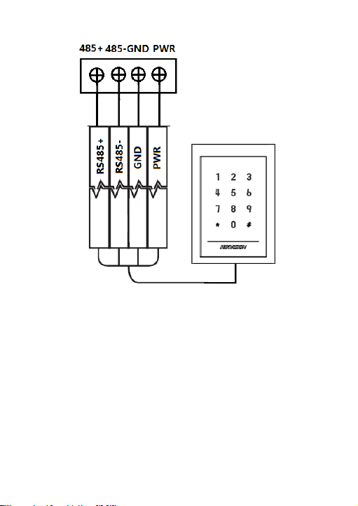
Yellow
Blue
Black
Red
Black
Red
Green
White
Purple
Controller
Card Reader
Figure 3-4 Wiring for RS-485 Communication Mode
Steps for Wiegand communication mode:
1. Set the DIP switch of No. 6 as 1.
2. Set the DIP switch of No. 5 and 7 for reading card mode and
Wiegand protocol. For details, please refer to 3.2
Introduction for DIP Switch.
3. W iring the cable between controller and card reader as
shown below.
8
Page 13
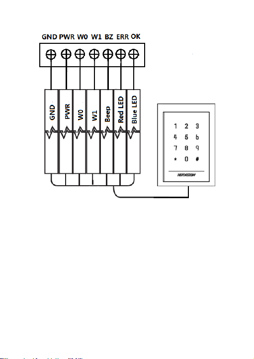
Black
Red
Green
White
Purple
Orange
Brown
Controller
Card Reader
Figure 3-5 Wiring for Wiegand Communication Mode
3.5 Installing Card Reader
Before you start:
Set the DIP switch. For details, refer to 3.2 Introduction for DIP
Switch.
9
Page 14

Installation for DS-K1101/ 02/ 03/ 04 series card reader
1. Fix the gang box on the wall or
other place.
2. Connect the cables between
controller and card reader. For
details, refer to 3.4 W iring
Cables.
3. Push the card reader to match
the fixed gang box.
4. Fasten the screw to keep the
components together.
5. Fix the side cover onto the card
reader, press the cover to make
it tightly fit the reader.
Steps:
Chapter 4 Sound Prompt and Indicator
After the card reader is powered on, LED status indicator will turn
blue and blink for 1 time. Then it will turn red and blink for 3
times. At last the buzzer will send out a beep sound indicating the
10
Page 15

starting up process is completed.
Sound Prompt
Description
One beep
RS-485 protocol: Pressing keys prompt;
Swiping card prompt; T ime out prompt for
pressing keys or swiping card.
Wiegand protocol: Pressing keys prompt;
Swiping card prompt.
Two rapid beeps
The operation of pressing keys or swiping
card is valid.
Three slow beeps
The operation of pressing keys or swiping
card is invalid.
Rapidly
continuous beeps
Alarm of tamper-proof.
Slowly continuous
beeps
The card reader is unencrypted.
LED Indicator Status
Description
Green and blinking
Card reader is working normally.
Solid green
The operation of pressing keys or swiping
card is valid.
Solid red
The operation of pressing keys or swiping
card is invalid.
Red and blinking
For RS-485 protocol: Registering failed or
card reader is offline. Failed to get key files
of PSAM card; Failed to detect the PSAM
card.
During using the card reader, it will send out different sounds
prompt and the LED indicator on it have different statuses. You
can refer to tables below for detailed information.
Table 4-1 Description of Prompt Sound
Table 4-2 Description of LED Indicator
11
Page 16

LED Indicator Status
Description
Red and Keeping
rapidly blinking
Available for reading file mode of CPU
card: PSAM is not inserted or undetected.
12
Page 17

13
 Loading...