

Page 1

Explosion-proof Dome·Quick Start Guide
0
Explosion-proof Dome
Quick Start Guide
UD04569B
Page 2

Explosion-proof Dome·Quick Start Guide
1
Quick Start Guide
COPYRIGHT © 2017 Hangzhou Hikvision Digital Technology Co., Ltd.
ALL RIGHTS RESERVED.
Any and all information, including, among others, wordings, pictures, graphs are the
properties of Hangzhou Hikvision Digital Technology Co., Ltd. or its subsidiaries
(hereinafter referred to be “Hikvision”). This user manual (hereinafter referred to be
“the Manual”) cannot be reproduced, changed, translated, or distributed, partially or
wholly, by any means, without the prior written permission of Hikvision. Unless
otherwise stipulated, Hikvision does not make any warranties, guarantees or
representations, express or implied, regarding to the manual.
About this Manual
This manual is applicable to Explosion-proof Dome.
The manual includes instructions for using and managing the product. Pictures, charts,
images and all other information hereinafter are for description and explanation only.
The information contained in the manual is subject to change, without notice, due to
firmware updates or other reasons. Please find the latest version in the company
website (http://overseas.hikvision.com/en/).
Please use this manual under the guidance of professionals.
Trademarks Acknowledgement
and other Hikvision’s trademarks and logos are the properties of Hikvision
in various jurisdictions. Other trademarks and logos mentioned below are the properties
of their respective owners.
Legal Disclaimer
TO THE MAXIMUM EXTENT PERMITTED BY APPLICABLE LAW, THE PRODUCT DESCRIBED,
WITH ITS HARDWARE, SOFTWARE AND FIRMWARE, IS PROVIDED “AS IS”, WITH ALL
FAULTS AND ERRORS, AND HIKVISION MAKES NO WARRANTIES, EXPRESS OR IMPLIED,
INCLUDING WITHOUT LIMITATION, MERCHANTABILITY, SATISFACTORY QUALITY,
FITNESS FOR A PARTICULAR PURPOSE, AND NON-INFRINGEMENT OF THIRD PARTY. IN
NO EVENT WILL HIKVISION, ITS DIRECTORS, OFFICERS, EMPLOYEES, OR AGENTS BE
LIABLE TO YOU FOR ANY SPECIAL, CONSEQUENTIAL, INCIDENTAL, OR INDIRECT
DAMAGES, INCLUDING, AMONG OTHERS, DAMAGES FOR LOSS OF BUSINESS PROFITS,
BUSINESS INTERRUPTION, OR LOSS OF DATA OR DOCUMENTATION, IN CONNECTION
WITH THE USE OF THIS PRODUCT, EVEN IF HIKVISION HAS BEEN ADVISED OF THE
POSSIBILITY OF SUCH DAMAGES.
REGARDING TO THE PRODUCT WITH INTERNET ACCESS, THE USE OF PRODUCT SHALL BE
WHOLLY AT YOUR OWN RISKS. HIKVISION SHALL NOT TAKE ANY RESPONSIBILITES FOR
ABNORMAL OPERATION, PRIVACY LEAKAGE OR OTHER DAMAGES RESULTING FROM
CYBER ATTACK, HACKER ATTACK, VIRUS INSPECTION, OR OTHER INTERNET SECURITY
RISKS; HOWEVER, HIKVISION WILL PROVIDE TIMELY TECHNICAL SUPPORT IF REQUIRED.
SURVEILLANCE LAWS VARY BY JURISDICTION. PLEASE CHECK ALL RELEVANT LAWS IN
YOUR JURISDICTION BEFORE USING THIS PRODUCT IN ORDER TO ENSURE THAT YOUR
Page 3

Explosion-proof Dome·Quick Start Guide
2
USE CONFORMS THE APPLICABLE LAW. HIKVISION SHALL NOT BE LIABLE IN THE EVENT
THAT THIS PRODUCT IS USED WITH ILLEGITIMATE PURPOSES.
IN THE EVENT OF ANY CONFLICTS BETWEEN THIS MANUAL AND THE APPLICABLE LAW,
THE LATER PREVAILS.
Page 4
Explosion-proof Dome·Quick Start Guide
3
Regulatory Information
FCC Information
Please take attention that changes or modification not expressly approved by the party
responsible for compliance could void the user’s authority to operate the equipment.
FCC compliance: This equipment has been tested and found to comply with the limits
for a Class A digital device, pursuant to part 15 of the FCC Rules. These limits are
designed to provide reasonable protection against harmful interference when the
equipment is operated in a commercial environment. This equipment generates, uses,
and can radiate radio frequency energy and, if not installed and used in accordance with
the instruction manual, may cause harmful interference to radio communications.
Operation of this equipment in a residential area is likely to cause harmful interference
in which case the user will be required to correct the interference at his own expense.
FCC Conditions
This device complies with part 15 of the FCC Rules. Operation is subject to the following
two conditions:
1. This device may not cause harmful interference.
2. This device must accept any interference received, including interference that may
cause undesired operation.
EU Conformity Statement
This product and - if applicable - the supplied accessories too are marked
with "CE" and comply therefore with the applicable harmonized European
standards listed under the EMC Directive 2014/30/EU, the RoHS Directive
2011/65/EU and the ATEX Directive 2014/34/EU.
2012/19/EU (WEEE directive): Products marked with this symbol cannot be
disposed of as unsorted municipal waste in the European Union. For proper
recycling, return this product to your local supplier upon the purchase of
equivalent new equipment, or dispose of it at designated collection points.
For more information see: www.recyclethis.info.
2006/66/EC (battery directive): This product contains a battery that cannot
be disposed of as unsorted municipal waste in the European Union. See the
product documentation for specific battery information. The battery is
marked with this symbol, which may include lettering to indicate cadmium
(Cd), lead (Pb), or mercury (Hg). For proper recycling, return the battery to your supplier
or to a designated collection point. For more information see: www.recyclethis.info.
Industry Canada ICES-003 Compliance
This device meets the CAN ICES-3 (A)/NMB-3(A) standards requirements.
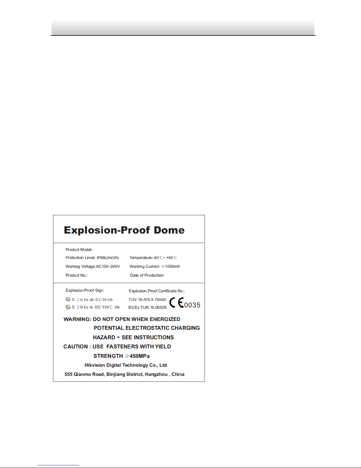
Intended Use of the Dome
AT EX: II 2GD Ex db IIC T6 Gb /Ex tb IIIC T80℃ Db IP68
IECEx: Ex db IIC T6 Gb /Ex tb IIIC T80℃ Db IP68
Page 5
Explosion-proof Dome·Quick Start Guide
4
Hazardous Area Classification: Zone 1, Zone 2, Zone 21, Zone 22
IP Degree: IP68 (2m, 2h)
Ex Standards:
IEC 60079-0: 2011 EN 60079-0: 2012
IEC 60079-1: 2014 EN 60079-1: 2014
IEC 60079-31: 2013 EN 60079-31: 2014
Special Conditions for Safe Use
1. Ambient temperature: -40°C - +60°C
2. DO NOT OPEN WHEN ENERGIZED
3. POTENTIAL ELECTROSTATIC CHARGING HAZARD – SEE INSTRUCTIONS
4. When assembly, operation and maintenance, the operator must follow the
requirements of the IEC 60079-14: latest version Explosive atmospheres- Part 14:
Electrical installations design, selection and erection, beside of the manufacturer’s
operating instructions or its National equivalent.
5. Repair and overhaul shall comply with IEC 60079-19: latest version or its National
equivalent.
Explosion-proof Speed Dome Nameplate
Page 6
Explosion-proof Dome·Quick Start Guide
5
Safety Instruction
These instructions are intended to ensure that user can use the product correctly to
avoid danger or property loss.
The precaution measure is divided into Warnings and Cautions:
Warnings: Neglecting any of the warnings may cause serious injury or death.
Cautions: Neglecting any of the cautions may cause injury or equipment damage.
Warnings
Grounding: The both internal and external earthing shall be connected reliably.
Ground wire cross-sectional area of not less than the phase connector cross-sectional
area level, at least 4mm2.
All the electronic operation should be strictly compliance with the electrical safety
regulations, fire prevention regulations and other related regulations in your local
region.
Make sure that the power has been disconnected before you wire, install or
disassemble the speed dome. Never wire, install or disassemble the speed dome in
explosive environment.
To avoid fire danger caused by electrostatic charge, never touch or wipe the speed
dome in explosive environment. Perform the wiping and replacing accessories only
under non-explosive environment with the provided glove.
When the speed dome is installed on wall or ceiling, the device shall be firmly fixed.
If smoke, odors or noise rise from the speed dome, turn off the power at once and
unplug the power cable, and then contact the service center.
If the speed dome does not work properly, contact your dealer or the nearest service
center. Never attempt to disassemble the speed dome yourself. (We shall not assume
any responsibility for problems caused by unauthorized repair or maintenance.)
Cautions
Do not drop the speed dome or subject it to physical shock, and do not expose it to
high electromagnetism radiation. Avoid installation on vibrations surface or places
subject to shock (ignorance can cause device damage).
To ensure explosion-proof performance, do not damage explosion-proof surface.
Warnings Follow
these safeguards to
prevent serious
injury or death.
Cautions Follow these
precautions to prevent
potential injury or
material damage.
Page 7

Explosion-proof Dome·Quick Start Guide
6
Do not place the speed dome in extremely hot (refer to the specification of the device
for the detailed operating temperature), cold, dusty or damp locations, and do not
expose it to high electromagnetic radiation.
The dome cover for indoor use shall be kept from rain and moisture.
Exposing the speed dome to direct sun light, low ventilation or heat source such as
heater or radiator is forbidden (ignorance can cause fire danger).
Do not aim the speed dome at the sun or extra bright places. A blooming or smear
may occur otherwise (which is not a malfunction however), and affecting the
endurance of sensor at the same time.
Use the provided glove when open up the dome cover, and avoid direct contact with
the dome cover, because the acidic sweat of the fingers may erode the surface coating
of the dome cover.
To prevent accumulation of electrostatic charge, use a soft and damp cloth when
clean inside and outside surfaces of the bubble. Do not use alkaline detergents.
Keep all wrappers after unpack them for future use. In case of any failure occurred,
you need to return the speed dome to the factory with the original wrapper.
Transportation without the original wrapper may result in damage on the speed dome
and lead to additional costs.
Improper use or replacement of the battery may result in hazard of explosion.
Replace with the same or equivalent type only. Dispose of used batteries according to
the instructions provided by the battery manufacturer.
Page 8

Explosion-proof Dome·Quick Start Guide
7
Table of Contents
1 Overview ...................................................................................................... 8
1.1 Explosion-proof Speed Dome Overview .................................................................. 8
1.2 Explanation of model naming .................................................................................. 8
1.3 Power Consumption ................................................................................................ 9
1.4 Explosion-proof Parameters .................................................................................... 9
1.5 Mechanical Specification ......................................................................................... 9
1.6 Working Environment .............................................................................................. 9
2 Installation ................................................................................................. 10
2.1 Preparation ............................................................................................................ 10
2.1.1 Basic Requirement .......................................................................................... 10
2.1.2 Checking Installing Environment ..................................................................... 10
2.1.3 Preparing Cables ............................................................................................. 10
2.1.4 Preparing Tools ................................................................................................ 10
2.1.5 Original Packaging ........................................................................................... 10
2.2 Cable Description ................................................................................................... 11
2.3 Installing the Explosion-proof Speed Dome ........................................................... 11
2.3.1 Cutting off the Cable Head .............................................................................. 11
2.3.2 Wall Mounting................................................................................................. 12
2.3.3 Pendant Mounting .......................................................................................... 15
2.3.4 Cable Entry Installation ....................................................................................17
2.3.5 Power-up Action .............................................................................................. 18
3 Setting the Dome over the LAN .................................................................. 19
3.1 Wiring .................................................................................................................... 19
3.2 Activating the Speed Dome ................................................................................... 19
3.2.1 Activation via Web Browser ............................................................................ 19
3.2.2 Activation via SADP Software .......................................................................... 20
3.3 Modifying the IP Address ....................................................................................... 21
4 Accessing via Web Browser ........................................................................ 23
Page 9

Explosion-proof Dome·Quick Start Guide
8
1 Overview
1.1 Explosion-proof Speed Dome Overview
The explosion-proof speed dome captures high quality colored images in dim light
environment with its low illumination and offers more details over expansive areas.
It is equipped with explosion-proof enclosure made of stainless steel. It can be widely
used in places such as: port, wharf, petrochemical industry, military industry.
Refer to Figure 1-1 for explosion-proof speed dome overview.
Figure 1-1 Explosion-proof Speed Dome Overview
1.2 Explanation of model naming
The product can be named by rules of Figure 1-2 and Figure 1-3.
Figure 1-2 Product Naming Rule 1
Page 10

Explosion-proof Dome·Quick Start Guide
9
Figure 1-3 Product Naming Rule 2
1.3 Power Consumption
For detailed information about the power supply voltage or power consumption, refer
to Explosion-proof Speed Dome Nameplate.
1.4 Explosion-proof Parameters
For detailed information, refer to Explosion-proof Performance Certification.
1.5 Mechanical Specification
Material: 304/316L Stainless Steel.
Cable outlet: One G 3/4 explosion-proof cable outlet, inner hole diameter Φ15.
1.6 Working Environment
Altitude (Above sea level): Within 2000m.
Humidity: Within 95%.
Temperature: Refer to Explosion-proof Performance Certification.
Note:
To ensure safety of the users and explosion-proof performance of the speed dome, your
installation environment must meet the installation requirements of the speed dome
you purchased.
Page 11

Explosion-proof Dome·Quick Start Guide
10
2 Installation
2.1 Preparation
2.1.1 Basic Requirement
All the electronic operation should be in strictly compliance with the electrical safety
regulations, fire prevention regulations and other related regulations in your local
region.
Check the package contents and make sure that the device in the package is in good
condition and all the assembly parts are included.
2.1.2 Checking Installing Environment
Make sure that there is enough space to install the device and accessories.
Make sure that the wall is strong enough to withstand at least eight times the weight
of the device and accessories.
2.1.3 Preparing Cables
You should prepare proper cables according to the actual network bandwidth,
transmission distance and installation environment:
Network Cable
Power Cable
2.1.4 Preparing Tools
Before installation, prepare the tools, such as the expansion screws, electric hammer,
electric drill, wrench, screwdriver, electroprobe and network cable.
2.1.5 Original Packaging
When you unpack the device, keep the original package properly, in case of returning or
repairing the camera, you can pack the device with the package.
Note:
The user should be responsible for any damage caused due to transporting in unoriginal
package.
Page 12

Explosion-proof Dome·Quick Start Guide
11
2.2 Cable Description
VIDEO
Power Cord
RS-485 Cable
CVBS Cable
Alarm Cable
Audio Cable
Optical Fiber
Network Cable
Figure 2-1 Cable Description
Notes:
The cables vary depending on different models of the speed dome.
2.3 Installing the Explosion-proof Speed Dome
Before you start:
Check the package contents and make sure that the device in the package is in good
condition and all the assembly parts are included.
We highly recommend that before installation, you apply power to the speed dome to
test it and make sure it can work normally.
Notes:
Do not drag the speed dome with its waterproof cables. The waterproof performance
is affected otherwise.
Do not touch the bubble directly by hand. The image blurs otherwise.
All installation operations shall be performed when the speed dome is powered off.
Do not disassemble the speed dome.
2.3.1 Cutting off the Cable Head
After testing the speed dome, cut off the cable head as shown in Figure 2-2.
Page 13

Explosion-proof Dome·Quick Start Guide
12
Do not cut off
the optical fiber
head
Cutting off the
Cable Head
Figure 2-2 Cutting off the Cable Head
Note:
Keep the cable head you cut off and you need to weld it back after installation.
2.3.2 Wall Mounting
Before you start:
Make sure that the wall is thick enough to withstand the expansion screws.
Make sure that the wall is strong enough to withstand more than eight times the
weight of the dome and the accessories.
There must be enough space for installing the explosion-proof speed dome and its
accessories.
Make sure the speed dome is power off before connecting the cables.
Steps:
1. Drill four screw holes for φ19 expansion screws in the wall, and fix the installation
plate onto the wall by inserting the four M12×130 expansion screws into the wall.
Make sure that mark is upward.
2. Insert the flag washer and the spring washer. Then tighten the four screws to secure
the installation plate as shown in Figure 2-3.
Page 14

Explosion-proof Dome·Quick Start Guide
13
Cable Outlet
168
4
-
Φ
19
214
Unit:mm
Figure 2-3 Install the Installation Plate
3. Route the cables into the bracket body. Insert three preassemble screws into the
preassemble screw holes on the cable joint (do not tighten the preassemble screws)
as shown in Figure 2-4.
Preassemble Screws
Cable Joint
Figure 2-4 Insert the Screws
4. Align the bracket with the cable joint and rotate the bracket clockwise until three
preassemble screws on the cable joint hooks onto three slots on the bracket as
shown in Figure 2-5.
Slots
Bracket
Figure 2-5 Rotate the Bracket
5. Screw three fixing screws into the fixing screws holes on the bracket. Then tighten
three preassemble screws to secure the speed dome as shown in Figure 2-6.
Page 15

Explosion-proof Dome·Quick Start Guide
14
Three Preassemble Screws
Figure 2-6 Secure the Speed Dome
6. Install the bracket to the installation plate.
1) Hang the safety rope to the speed dome and the hook on the bracket.
2) Route the cables of the speed dome through the bracket and connect the
corresponding cables.
3) Hang the speed dome to the bracket by aligning the holes of bracket with the
screws and move the speed dome downward to secure the speed dome as
shown as Figure 2-7.
Figure 2-7 Install Bracket to Installation Plate
7. Secure the bracket by putting in the flat washer and the spring washer. Then tighten
the gland nut.
Explosion-proof
Junction Box
(Optional)
Figure 2-8 Secure the Bracket
8. Tear off the protective film on the bubble after the installation is finished.
Page 16

Explosion-proof Dome·Quick Start Guide
15
2.3.3 Pendant Mounting
Before you start:
Make sure the ceiling is thick enough to withstand the expansion screws.
Make sure the ceiling must be strong enough to withstand more than eight times the
weight of the dome and its accessories.
There must be enough space for installing the explosion-proof speed dome and its
accessories.
Make sure the speed dome is power off before connecting the cables.
Steps:
1. Drill four screw holes for φ19 expansion screws in the wall, and fix the installation
plate onto the wall by inserting the four M12×130 expansion screws into the wall.
Make sure that mark is at the cable outlet and is upward.
2. Insert the flag washer and the spring washer. Then tighten the four screws to secure
the installation plate as shown in Figure 2-9.
Cable Outlet
168
214
4-Φ19
Unit:mm
Figure 2-9 Install the Installation Plate
3. Route the cables into the bracket body. Insert three preassemble screws into the
preassemble screw holes on the cable joint (do not tighten the preassemble screws)
as shown in Figure 2-10.
Preassemble Screws
Cable Joint
Figure 2-10 Insert the Screws
4. Align the bracket with the cable joint and rotate the bracket clockwise until three
preassemble screws on the cable joint hooks onto three slots on the bracket as
shown in Figure 2-11.
Page 17

Explosion-proof Dome·Quick Start Guide
16
Slots
Bracket
Figure 2-11 Rotate the Bracket
5. Screw three fixing screws into the fixing screws holes on the bracket. Then tighten
three preassemble screws to secure the speed dome as shown in Figure 2-12.
Three Preassemble Screws
Figure 2-12 Secure the Speed Dome
6. Install the bracket to the installation plate.
1) Hang the safety rope to the speed dome and the hook on the bracket.
2) Route the cables of the speed dome through the bracket and connect the
corresponding cables.
3) Hang the speed dome to the bracket by aligning the holes of bracket with the
screws and move the speed dome following the direction in Figure 2-13 to
secure the speed dome.
Figure 2-13 Install Bracket to Installation Plate
7. Secure the bracket by putting in the flat washer and the spring washer. Then tighten
the gland nut.
Page 18

Explosion-proof Dome·Quick Start Guide
17
Explosion-proof
Junction Box (Optional)
Figure 2-14 Secure the Bracket
8. Tear off the protective film on the bubble after the installation is finished.
2.3.4 Cable Entry Installation
Purpose:
To ensure the explosion-proof performance of the speed dome, you shall route the cable
through the cable entry to protect the cables after speed dome installation.
Steps:
1. Loosen and take off the gland nut of the cable entry.
Gland Nut
Figure 2-15 Take off Gland Nut
2. Seal the cable entry by routing the cables through the sealing ring, washer, and gland
nut in order as shown in Figure 2-16.
Page 19

Explosion-proof Dome·Quick Start Guide
18
Sealing Ring
Washer
Gland Nut
Figure 2-16 Seal the Cable Entry
3. Weld the cables heads back.
2.3.5 Power-up Action
Make sure all cables are connected properly. Then power on the device to perform the
power-up action.
The device does self-test actions automatically, and then you can get the live view and
check whether the PTZ control can work normally.
Note:
If the speed dome cannot be powered up without damage, check the cable connection
carefully.
Connect the cable with machine room
through cable trunk or cable tray.
Junction Box
Cable Entry
Figure 2-17 Cable Wiring Diagram
Page 20

Explosion-proof Dome·Quick Start Guide
19
3 Setting the Dome over the LAN
Notes:
You shall acknowledge that the use of the product with Internet access might be
under network security risks. For avoidance of any network attacks and information
leakage, strengthen your own protection. If the product does not work properly,
contact with your dealer or the nearest service center.
To ensure the network security of the speed dome, we recommend you to have the
speed dome assessed and maintained termly. You can contact us if you need such
service.
3.1 Wiring
To view and configure the speed dome via LAN (Local Area Network), you need to
connect the network speed dome in the same subnet with your PC. Then, install the
SADP or client software to search and change the IP of network speed dome.
The following figure shows the cable connection of network speed dome.
Network
Speed Dome
Switch
Internet
NVR
PC
Figure 3-1 Wiring over LAN
3.2 Activating the Speed Dome
Purpose:
You are required to activate the speed dome first by setting a strong password for it
before you can use the speed dome.
Activation via Web Browser, Activation via SADP, and Activation via client software are
supported. In the following sections, activation via web browser and SADP will be taken
as examples. You may refer to the user manual of the speed dome for the details of
activation via client software.
3.2.1 Activation via Web Browser
Steps:
1. Power on the speed dome, and connect the speed dome to the network.
Page 21

Explosion-proof Dome·Quick Start Guide
20
2. Input the IP address into the address bar of the web browser, and click Enter to enter
the activation interface.
Note:
The default IP address of the speed dome is 192.168.1.64.
Figure 3-2 Activation Interface(Web)
3. Create a password and input the password into the password field.
STRONG PASSWORD RECOMMENDED– We highly recommend you create a
strong password of your own choosing (Using a minimum of 8 characters,
including at least three of the following categories: upper case letters, lower
case letters, numbers, and special characters.) in order to increase the
security of your product. And we recommend you reset your password
regularly, especially in the high security system, resetting the password
monthly or weekly can better protect your product.
4. Confirm the password.
5. Click OK to activate the speed dome and enter the live view interface.
3.2.2 Activation via SADP Software
SADP software is used for detecting the online device, activating the device, and
resetting the password.
Get the SADP software from the supplied disk or the official website, and install the
SADP according to the prompts. Follow the steps to activate the speed dome.
Steps:
1. Run the SADP software to search the online devices.
2. Check the device status from the device list, and select an inactive device.
Page 22

Explosion-proof Dome·Quick Start Guide
21
Figure 3-3 SADP Interface
3. Create a password and input the password in the password field, and confirm the
password.
STRONG PASSWORD RECOMMENDED– We highly recommend you create a
strong password of your own choosing (Using a minimum of 8 characters,
including at least three of the following categories: upper case letters, lower
case letters, numbers, and special characters.) in order to increase the security
of your product. And we recommend you reset your password regularly,
especially in the high security system, resetting the password monthly or
weekly can better protect your product.
4. Click OK to save the password.
You can check whether the activation is completed on the popup window. If activation
failed, make sure that the password meets the requirement and then try again.
3.3 Modifying the IP Address
Purpose:
To view and configure the speed dome via LAN (Local Area Network), you need to
connect the network speed dome in the same subnet with your PC. Then, install the
SADP software or client software to search and change the IP of network speed dome.
We will take modifying the IP Address via SADP software as an example to introduce the
IP address modification.
Steps:
1. Run the SADP software.
Page 23

Explosion-proof Dome·Quick Start Guide
22
2. Click to select an active device.
Note:
Refer to Section 3.2 Activating the Speed Dome to activate the speed dome if it is
inactive.
3. Change the device IP address to the same subnet with your computer by either
modifying the IP address manually or checking the checkbox of Enable DHCP.
Figure 3-4 Modify the IP Address
4. Input the password and click Save to activate your IP address modification.
Page 24

Explosion-proof Dome·Quick Start Guide
23
4 Accessing via Web Browser
System Requirement:
Operating System: Microsoft Windows XP SP1 and above version / Vista / Win7 /
Server 2003 / Server 2008 32bits
CPU: Intel Pentium IV 3.0 GHz or higher
RAM: 1G or higher
Display: 1024×768 resolution or higher
Web Browser: Internet Explorer 7.0 and above version, Apple Safari 5.02 and above
version, Mozilla Firefox 5 and above version and Google Chrome8 and above version
Steps:
1. Open the web browser.
2. In the browser address bar, input the IP address of the network speed dome, e.g.,
192.168.1.64 and press the Enter key to enter the login interface.
3. To activate the speed dome for the first time using, refer to the Section 3.2
Activating the Speed Dome.
4. Input the user name and password and click .
The admin user should configure the device accounts and user/operator
permissions properly. Delete the unnecessary accounts and user/operator
permissions.
Note:
The device IP address gets locked if the admin user performs 7 failed password
attempts (5 attempts for the user/operator).
Figure 4-1 Login Interface
5. Install the plug-in before viewing the live video and managing the network speed
dome. Follow the installation prompts to install the plug-in.
Note:
You may have to close the web browser to finish the installation of the plug-in.
Page 25

Explosion-proof Dome·Quick Start Guide
24
Figure 4-2 Download Plug-in
6. Reopen the web browser after the installation of the plug-in and repeat the above
steps 2-4 to login.
Note:
For detailed instructions of further configuration, refer to the user manual of
network speed dome.
0504081070209
Page 26

 Loading...