

Page 1
19/22/224-inch LCD Display Unit
User Manual
PN:G6AUM185000001
Page 2

Thank you for purchasing
I
This manual may contain several technically incorrect places or printing errors, and the content is subject to
change without notice. The updates will be added into the new version of this manual. We will readily
improve or update the products or described in the manual.
our product. If there is any question or request, please do not hesitate to contact us.
Page 3
Hikvision® 19/22/24-inch LCD Display Unit User’s Manual
(
y
p
y
quip
p
p
This manual, as well as the software described in it, is furnished under license and may be
used or copied only in accordance with the terms of such license. The content of this
manual is furnished for informational use only, is subject to change without notice, and
should not be construed as a commitment by Hikvision Digital Technology Co., Ltd.
(Hikvision). Hikvision assumes no responsibility or liability for any errors or inaccuracies
that may appear in the book.
Except as per
in a retrieval system, or transmitted, in any form or by any means, electronic, mechanical,
recording, or otherwise, without the prior written permission of Hikvision.
HIKVISION MAKES NO WARRANTIES, EXPRESS OR IMPLIED, INCLUDING WITHOUT
LIMITATION THE IMPLIED WARRANTIES OF MERCHANTABILITY AND FITNESS FOR A
PARTICULAR PURPOSE, REGARDING THE HIKVISION SOFTWARE. HIKVISION DOES NOT
WARRANT, GUARANTEE, OR MAKE ANY REPRESENTATIONS REGA
RESULTS OF THE USE OF THE HIKVISION SOFTWARE IN TERMS OF ITS CORRECTNESS,
ACCURACY, RELIABILITY, CURRENTNESS, OR OTHERWISE. THE ENTIRE RISK AS TO THE
RESULTS AND PERFORMANCE OF THE HIKVISION SOFTWARE IS ASSUMED BY YOU. THE
EXCLUSION OF IMPLIED WARRANTIES IS NOT PERMITTED BY SOME STATES. THE ABOVE
EXCLUSION MAY NOT APPLY TO YOU.
IN NO EVENT WILL HIKVISION, ITS DIRECTORS, OFFICERS, EMPLOYEES, OR AGENTS BE
LIABLE TO YOU FOR ANY CONSEQUENTIAL, INCIDENTAL, OR INDIRECT DAMAGES
(INCLUD
OF BUSINESS INFORMATION, AND THE LIKE) A RISING OUT OF THE USE OR INABILITY TO
USE THE HIKVISION SOFTWARE EVEN IF HIKVISION HAS BEEN ADVISED OF THE
POSSIBILITY OF SUCH DAMAGES. BECAUSE SOME STATES DO NOT ALLOW THE EXCLUSION
OR LIMITATION OF LIABILITY FOR CONSEQUENTIAL OR INCIDENTAL DAMAGES, THE ABOVE
LIMITATIONS MAY NOT APPLY TO YOU.
mitted by such license, no part of this publication may be reproduced, stored
RDING THE USE OR THE
ING DAMAGES FOR LOSS OF BUS INESS PROFITS, BUSINESS INTERRUPTION, LOSS
Regulatory Information
2002/96/EC
mbol cannot be disposed of as unsorted municipal waste in the
s
Euro
ean Union. Forproper recycling, return thisproduct to
our local supplier upon thepurchase of equivalent new
e
ment, or dispose of it at designated collectionpoints. For
more information see: www.recyclethis.info.
WEEE directive):Products marked with this
2006/66/EC (battery directive): This product contains a battery
that cannot be dis
ean Union. See theproduct documentation for specific
Euro
osed of as unsorted municipal waste in the
battery information. The battery is marked with this symbol, which may
include lettering to indicate cadmium (Cd), lead (Pb), or mercu ry (Hg). For
proper recycling, return the battery to your supplier or to a des ignate d
collection point. For more information see: www.recyclethis.info.
II
Page 4
Chapter1. Introduction
1.1 Key Features
DS-D5019 Series:Support 1366×768 HD display;
DS-D5022/5024 Series:Supports 1920×1080 FHD dispiay;
User-friendly operation menu;
Three image modes to adapt different environment;
1 channel HDMI 1.3 input interface;
Support software spread-spectrum technology to reduce EMI radiation;
Standby Power Consumption is lower than 0.5W;
DS-D5019:Viewing Angle:Horizontal 90°,
DS-D5022/24:Viewing Angle:Horizontal 170°, Vertical 160º ;
2Wx2 Speakers efficient output;
1.2 Power Supply Connection
Insert the 3-pin power device into well-grounded socket and turn the rocker switch on.
Vertical 65º ;
Figure 1.1 Power Input
Power input specification from 100VAC to 240VAC orprovide automatic switchingbetween
high line and low line input ranges.
Turn off the mainpower switch of the displayunit, andpull theplugfrom thepower outlet if
the display unit will not be used for a long time.
Never connect the device to a DC power.
1
Page 5
Chapter2. Device I nterfaces
Figure 2.1 Rear Panel of Device
Interfaces
POWER IN Power Input
VGA IN
HDMI IN
AUDIO IN
Interfaces
Power Input
VGA Analog Signal Input
1
Interfaces Interfaces
VGA Analog Signal Input
HDMI Digital Signal Input
Chapter3. Panel Keys
2
Interfaces
Interfaces
Interfaces
1
2
3
Power Input
VGA Analog Signal Input
HDMI Digital Signal Input
Audio Inpu
3
t
Keys on lower right corner of the display unit panel are shown in the Figure 3.1 Keys on the Display
Unit.
Figure 3.1 Keys on the Display Unit
The functions of the keys on lower right corner of the display unit vary according to different situations.
2
Page 6
Chapter4. Basic Operation
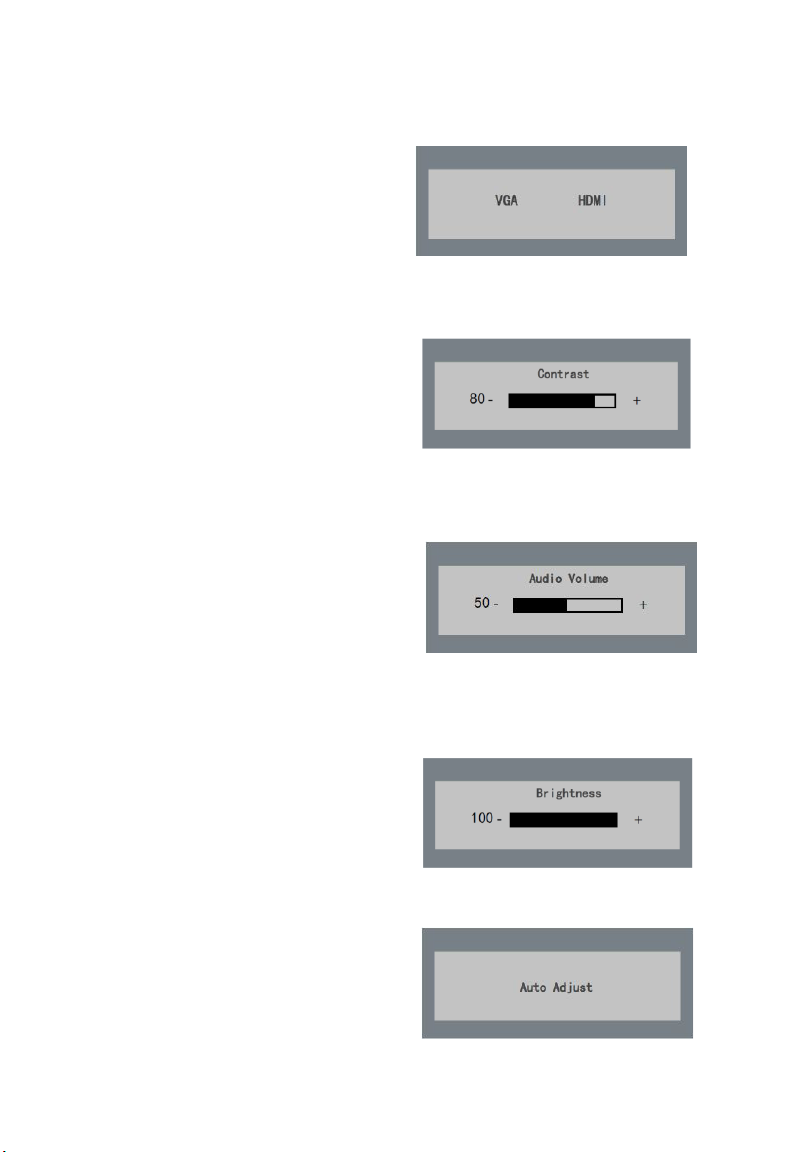
4.1 Input Source Selection(optional)
Turn on the display unit when the power supply is on
and input source is confirmed.
Press ◄ key of the remote controller to enter the menu
as shown on the right. DS-D5019/22 /24inch LCD
display unit includes 2 input sources as HDMI and
VGA signal. Press direction keys to select the input
source and press MENU to accomplish the input
source selection.
4.1 Contrast
Press
key of the remote controller to enter the menu
◄
as shown on the right
of contrast.
adjustment.
Press MENU to accomplish the contrast
4.2 Input Audio Volume Adjustment(optional)
Turn on the display unit when the power supply is on
and input source is confirmed.
Press
► key of the remote controller to enter the menu
as shown on the right.
of volume.
adjustment.
4.2
press MENU to accomplish the volume
Brightness
.
press ◄ or ► to adjust the value
press ◄ or ► to adjust the value
Figure 4.1 Input Source
Figure 4.1 Input Source
Figure 4.2 Audio Volume
►
Press
► key of the remote controller to enter the menu
as shown on
Brightness. press MENU to accomplish the Brightness
adjustment.
the right.press ◄ or ► to adjust the value of
4.3 Auto Adjust
Turn on the display unit when the power supply is on
and input source is confirmed.
Press
AUTO key of the remote controller to enter the
menu as shown on the right(In VGA Signal).
Figure 4.2 Brightness
Figure 4.3 Input Source
3
Page 7

4.4 Main Menu
4.4.1 Image Settings
Gray indicates that under current mode or current input source condition it is not adjustable; Yellow
Figure 4.4.1 Image Settings
4
Purpose:
You can adjust the picture parameters by switching image modes and adjust the values of contrast,
brightness, color temperature,auto adjust,color adjust.
Steps:
Press MENU key to enter the main menu interface as shown below.
1.
2. Press MENU key to enter the setting you want.
3. Press ◄ or ► to adjust the value. It applies for adjusting contrast, brightness, color temp and other
parameters.
Contrast, Brightness: Press ◄ or ► to set the contrast, the range varies from 0-100.
Color temperature :Press ◄ or ► to set the color temperature you need.
indicates that it is adjustable.
4.Press AUTO key to return to the main menu after accomplishing the adjustment.
Page 8

4.4.2 Image Adjustment
Figure 4.4.2 Image Adjustment
5
Purpose:
When the input source is selected VGA, you can adjust the VGA parameters. It is for adjusting
VGA H position, V Position, clock and phase.
Steps:
1. Press Menu key to enter the main menu interface.
2. Press ◄ key to enter the VGA parameter setting interface. (You can select Auto Adjust and press ◄
or ► to adjust the VGA parameters automatically or adjust it manually)
3. Select H Position and press ◄ or ► to adjust the H Position
4. Select V Position and press ◄ or ► to adjust the V pos
5. Selec
6. Select Phase and press ◄ or ► to adjust the phase.
7. Press MENU key to return to the main menu after accomplishing the adjustment.
lock and press ◄ or ► to adjust the clock.
t C
The range of the adjustment varies between 0-100.
ition.
Page 9

4.4.3 OSD Setting
6
Purpose:
You can set the language, blending and OSD duration of the menu.
Steps:
1. Press M ENU key to enter the main menu interface.
2. Press ◄ key twice and press MENU key to enter the【Language】interface, press ◄ or ► to switch
the language you want.
3. Select OSD H.Pos/OSD V.Pos to adjust the position of OSD with ◄ or ►.
4. Select OSD Timer to adjust the OSD duration with ◄ or ►: 5Sec~60Sec.
5. Select Transparency to adjust the OSD transparency value with ◄ or ►.
6. Press AUTO key to return to the main menu after accomplishi
ng the adjustment.
Figure 4.4.3 OSD Setting
Page 10

4.4.4 Other Settings
7
Purpose:
You can set Mode,Audio Volume,Signal Source,Aspect Ratio,DCR.
Steps:
1. Press M
2. Press triple◄ key and press MENU key to enter the Mode interface, press ◄ or ► to switch the mode
3. Press ◄ or ► to adjust the Audio Volume from0~100(optional).
4. Press ◄ or ► to change the Signal Source between VGA and HDMI(optional) .
5. Press ◄ or ► to switch the Aspect Ratio between 16:9/AUTO/4:3.
6. Press ◄ or ► to switch the DCR On/Off.
7. Press MENU key to return to the main menu after accomplishing the adjustment.
ENU key to enter the main menu interface.
between PC/GAME/MOVIE.
Figure4.4.4 Other Settings
Page 11

4.4.5 Reset Setting
8
Purpose:
You can reset settings to the factory defaults.
Steps:
1.Press M
ENU key to enter the main menu interface.
2.Press ◄ key 4 times and press MENU key to
Figure 4.4.5 Reset Setting
reset settings to the factory defaults.
Page 12

9
Appendix: Specifications
Device Model DS-D5019
Display Type
Screen Size
Color 16.7M
Dot Pitch 0.300×0.300 mm
Max Resolution 1366×768
Best Operation Resolution 1366×768@60Hz
Brightness 200cd/m²
Contrast 600:1
Viewing Angle
Viewable Area 409.8×230.4mm
Interfaces
Power Supply AC 100-240V; 50/60Hz
Consumption ≤25W
Standby Power
Consumption
Operation Temperature 0°C~40°C (32°F~104°F)
Operation Humidity 10%~85%
Storage Temperature: -20°C~55°C (-4°F~131°F)
Storage Humidity: 5%~95%
Bezel Material Plastic
Bezel Color Black
Wall-mounting Dot Site 75×75mm
Wall-mounting Thread M4
Device Dimensions 446×335×148mm
Package Dimensions 490×333×101mm
G.W. 3.5Kg
N.W. 2.8Kg
Standard Package
TFT-LED Backlight
18.5"
Hor
VGA Input Port
AC Input Port
HDMI Input Port
AUDIO Input Port
≤0.5W
Display Unit 1
VGA Cord 1
User Manual 1
Power Cord 1
Audio Cord 1
Series
izontal 90°, Vertical 65º
(optional)
Interfaces 1
1
1
NA
NA
Interfaces 2 Interfaces 3
1
1
1
NA
1
1
1
1
Page 13

tructure Figure
S
147.62
41.97
44.60
18.10
1.95
17.89
231.80
445.58
411.20
274.99
84.63
200.13
130.6
75.00
10
75.00
70.50
40.50
180.29
Page 14

Appendix: Specifications
Device Model DS-D5022 Series
Display Type TFT-LED Backlight
Screen Size 21.5"
Dot Pitch 0.248×0.248 mm
Max Resolution 1920×1080
Best Operation Resolution 1920×1080@60Hz
Brightness 250cd/m²
Contrast 1000:1
Color 16.7M
Viewable Area
Viewing Angle Horizontal 170°, Vertical 160º
Interfaces2
ower Supply AC 100-240V; 50/60Hz
P
Consumption ≤30W
Standby Power
Consumption
Operation Temperature 0°C~40°C (32°F~104°F)
Operation Humidity 10%~85%
Storage Temperature: -20°C~55°C (-4°F~131°F)
Storage Humidity: 5%~95%
Bezel Material Plastic
Bezel Color Black
Wall-mounting Dot Site 100×100mm
Wall-mounting Thread M4
Device Dimensions
Package Dimensions 561×426×103mm
G.W. 4.5Kg
N.W. 3.3Kg
Standard Package
477×268mm
VGA Input Port 1
HDMI Input Port
AC Input Port
AUDIO Input Port
≤0.5
W
511×377×170mm
Display Unit 1
VGA Cord 1
User Manual 1
Power Cord 1
Interfaces 2
1
1
NA
Interfaces 3
1
1
1
1
11
Page 15

Structure F igur e
511mm
12
Page 16

Appendix: Specifications
Device Model
Display Type
Screen Size
Color 16.7M
Dot Pitch 0.271×0.271mm
Max Resolution
Best Operation Resolution
Brightness
Contrast
Viewing Angle
Viewable Area
Interfaces
Power Supply AC 100-240V; 50/60Hz
Consumption
Standby Power
Consumption
Operation Temperature 0°C~40°C (32°F~104°F)
Operation Humidity 10%~85%
Storage Temperature: -20°C~55°C (-4°F~131°F)
Storage Humidity: 5%~95%
Bezel Material Plastic
Bezel Color Black
Wall-mounting Dot Site
Wall-mounting Thread M4
Device Dimensions 560×399×220mm
Package Dimensions
G.W.
N.W.
Standard Package
DS-D5024
TFT-LED Backlight
23.6"
1920×1080
1920×1080@60Hz
250cd/m²
1000:1
Hor
521×293mm
VGA Input Port
AC Input Port
HDMI Input Port
AUDIO Input Port
≤30W
≤0.5W
100×100mm
614×465×109mm
5.4Kg
4.5Kg
Display Unit 1
VGA Cord 1
User Manual 1
Power Cord 1
Audio Cord 1
Series
izontal 170°, Vertical 160º
(optional)
Interfaces 2
1
1
1
NA
Interfaces 3
1
1
1
1
13
Page 17

Structure Figure
14
Page 18

13
 Loading...