

Page 1
User Manual of DS-C10S Series Video Wall Controller
DS-C10S Series Video Wall Controller
User Manual (V2.0)
UD.6L0203D1184A01
0
Page 2

User Manual of DS-C10S Series Video Wall Controller
User Manual
COPYRIGHT © 2015 Hangzhou Hikvision Digital Technology Co., Ltd.
ALL RIGHTS RESERVED.
Any and all information, including, among others, wordings, pictures, graphs are the properties of Hangzhou
Hikvision Digital Technology Co., Ltd. or its subsidiaries (hereinafter referred to be “Hikvision”). This user manual
(hereinafter referred to be “the Manual”) cannot be reproduced, changed, translated, or distributed, partially or
wholly, by any means, without the prior written permission of Hikvision. Unless otherwise stipulated, Hikvision
does not make any warranties, guarantees or representations, express or implied, regarding to the Manual.
About this Manual
This Manual is applicable to DS-C10S Series Video Wall Controller.
The Manual includes instructions for using and managing the product. Pictures, charts, images and all other
information hereinafter are for description and explanation only. The information contained in the Manual is
subject to change, without notice, due to firmware updates or other reasons. Please find the latest version in the
company website (http://overseas.hikvision.com/en/).
Please use this user manual under the guidance of professionals.
Trademarks Acknowledgement
and other Hikvision’s trademarks and logos are the properties of Hikvision in various jurisdictions.
Other trademarks and logos mentioned below are the properties of their respective owners.
Legal Disclaimer
TO THE MAXIMUM EXTENT PERMITTED BY APPLICABLE LAW, THE PRODUCT DESCRIBED, WITH ITS HARDWARE,
SOFTWARE AND FIRMWARE, IS PROVIDED “AS IS”, WITH ALL FAULTS AND ERRORS, AND HIKVISION MAKES NO
WARRANTIES, EXPRESS OR IMPLIED, INCLUDING WITHOUT LIMITATION, MERCHANTABILITY, SATISFACTORY
QUALITY, FITNESS FOR A PARTICULAR PURPOSE, AND NON-INFRINGEMENT OF THIRD PARTY. IN NO EVENT WILL
HIKVISION, ITS DIRECTORS, OFFICERS, EMPLOYEES, OR AGENTS BE LIABLE TO YOU FOR ANY SPECIAL,
CONSEQUENTIAL, INCIDENTAL, OR INDIRECT DAMAGES, INCLUDING, AMONG OTHERS, DAMAGES FOR LOSS OF
BUSINESS PROFITS, BUSINESS INTERRUPTION, OR LOSS OF DATA OR DOCUMENTATION, IN CONNECTION WITH
THE USE OF THIS PRODUCT, EVEN IF HIKVISION HAS BEEN ADVISED OF THE POSSIBILITY OF SUCH DAMAGES.
REGARDING TO THE PRODUCT WITH INTERNET ACCESS, THE USE OF PRODUCT SHALL BE WHOLLY AT YOUR OWN
RISKS. HIKVISION SHALL NOT TAKE ANY RESPONSIBILITES FOR ABNORMAL OPERATION, PRIVACY LEAKAGE OR
OTHER DAMAGES RESULTING FROM CYBER ATTACK, HACKER ATTACK, VIRUS INSPECTION, OR OTHER INTERNET
SECURITY RISKS; HOWEVER, HIKVISION WILL PROVIDE TIMELY TECHNICAL SUPPORT IF REQUIRED.
SURVEILLANCE LAWS VARY BY JURISDICTION. PLEASE CHECK ALL RELEVANT LAWS IN YOUR JURISDICTION BEFORE
USING THIS PRODUCT IN ORDER TO ENSURE THAT YOUR USE CONFORMS THE APPLICABLE LAW. HIKVISION SHALL
NOT BE LIABLE IN THE EVENT THAT THIS PRODUCT IS USED WITH ILLEGITIMATE PURPOSES.
IN THE EVENT OF ANY CONFLICTS BETWEEN THIS MANUAL AND THE APPLICABLE LAW, THE LATER PREVAILS.
1
Page 3
DS-C10S Series Video Wall Controller User Manual
Regulatory Information
FCC Information
FCC compliance: This equipment has been tested and found to comply with the limits for a Class A digital device,
pursuant to part 15 of the FCC Rules. These limits are designed to provide reasonable protection against harmful
interference when the equipment is operated in a commercial environment. This equipment generates, uses, and
can radiate radio frequency energy and, if not installed and used in accordance with the instruction manual, may
cause harmful interference to radio communications. Operation of this equipment in a residential area is likely to
cause harmful interference in which case the user will be required to correct the interference at his own expense.
FCC Conditions
This device complies with part 15 of the FCC Rules. Operation is subject to the following two conditions:
1. This device may not cause harmful interference.
2. This device must accept any interference received, including interference that may cause undesired operation.
EU Conformity Statement
This product and - if applicable - the supplied accessories too are marked with "CE" and comply
therefore with the applicable harmonized European standards listed under the EMC Directive
2004/108/EC, the RoHS Directive 2011/65/EU, the Low Voltage Directive 2006/95/EC.
2012/19/EU (WEEE directive): Products marked with this symbol cannot be disposed of as unsorted
municipal waste in the European Union. For proper recycling, return this product to your local
supplier upon the purchase of equivalent new equipment, or dispose of it at designated collection
points. For more information see: www.recyclethis.info
2006/66/EC (battery directive): This product contains a battery that cannot be disposed of as
unsorted municipal waste in the European Union. See the product documentation for specific
battery information. The battery is marked with this symbol, which may include lettering to indicate
cadmium (Cd), lead (Pb), or mercury (Hg). For proper recycling, return the battery to your supplier or to a
designated collection point. For more information see: www.recyclethis.info
Industry Canada ICES-003 Compliance
This device meets the CAN ICES-3 (A)/NMB-3(A) standards requirements.
2
Page 4

DS-C10S Series Video Wall Controller User Manual
Product Module
Product Name
DS-C10S
Video Wall Controller
iVMS-4200
Client Software for Video Wall Controller
Thank you for purchasing our product. If there is any question or request, please do not hesitate to contact us.
This manual is applicable to following product:
To simplify the description in this user manual, we make conventions as follows in this manual:
The DS-C10S series video wall controller client is defined as software
The video wall controller (DS-C10S) is defined as controller
Click refers to click by using the left key of mouse, double-click refers to quickly press the left mouse button
twice, right-click refers to press the right mouse button once.
3
Page 5

User Manual of DS-C10S Series Video Wall Controller
Table of Contents
Chapter 1 DS-C10S Series Controller Introduction.......................................................................................... 6
1.1 Overview ........................................................................................................................................... 6
1.2 Product Features ............................................................................................................................... 6
1.3 Product Introduction ......................................................................................................................... 7
1.3.1 Available Models .......................................................................................................... 7
1.3.2 Assembly Introduction ................................................................................................. 7
1.4 Panel Introduction ............................................................................................................................. 9
1.4.1 Front Panel ................................................................................................................... 9
1.4.2 Rear Panel .................................................................................................................. 11
1.4.3 Motherboard ............................................................................................................. 13
1.4.4 Input Module ............................................................................................................. 14
1.4.5 Output Module .......................................................................................................... 17
1.5 Specification .................................................................................................................................... 19
Chapter 2 Overview of Client Software ........................................................................................................ 21
2.1 Features .......................................................................................................................................... 21
2.2 Working Environment ..................................................................................................................... 21
2.3 Performance .................................................................................................................................... 21
Chapter 3 Client Software Installation and Uninstallation ............................................................................ 22
3.1 Installing Software ........................................................................................................................... 22
3.2 Uninstalling Software ...................................................................................................................... 22
3.3 User Registration and Login ............................................................................................................ 23
3.3.1 Registration ................................................................................................................ 23
3.3.2 Login .......................................................................................................................... 23
3.4 Using the Wizard for Basic Configuration ........................................................................................ 24
3.5 GUI Introduction ............................................................................................................................. 27
Chapter 4 Video Wall Client Management ................................................................................................... 28
4.1 Account Management ..................................................................................................................... 28
4.2 System Configuration ...................................................................................................................... 29
4.2.1 General Settings ......................................................................................................... 29
4.2.2 File Saving Path Settings............................................................................................. 30
4.3 Device Management ....................................................................................................................... 31
4.3.1 Setting Admin Password for a Device......................................................................... 31
4.3.2 Adding a Device ......................................................................................................... 32
4.4 Remote Configuration ..................................................................................................................... 34
4.4.1 System Settings .......................................................................................................... 34
4.4.2 Network Settings........................................................................................................ 35
4.4.3 Event Settings ............................................................................................................ 35
4.4.4 Video Display Settings ................................................................................................ 36
4.4.5 Other Settings ............................................................................................................ 37
4.5 Video Wall Introduction .................................................................................................................. 38
4.6 Screen Control ................................................................................................................................. 40
Chapter 5 Video Wall Management ............................................................................................................. 41
4
Page 6

DS-C10S Series Video Wall Controller User Manual
5.1 Adding Video Wall ........................................................................................................................... 41
5.2 Displaying Signals on the Video Wall ............................................................................................... 42
5.2.1 Preview Image............................................................................................................ 42
5.2.2 Putting on Video Wall ................................................................................................ 42
5.3 Configuring Signal Sources .............................................................................................................. 43
5.4 Configuring Cameras ....................................................................................................................... 44
5.4.1 Adding a Camera ........................................................................................................ 44
5.4.2 Adding a Group .......................................................................................................... 45
5.4.3 Modifying the Group.................................................................................................. 45
5.5 Creating and Displaying Scene ........................................................................................................ 46
5.5.1 Creating a Scene ........................................................................................................ 46
5.5.2 Calling a Scene ........................................................................................................... 46
5.6 Creating and Scheduling Plan .......................................................................................................... 47
5.6.1 Creating a Plan ........................................................................................................... 47
5.6.2 Calling a Plan .............................................................................................................. 48
5.7 Advanced Settings ........................................................................................................................... 49
5.7.1 Configuring Screen Layout ......................................................................................... 49
5.7.2 Adjusting Screens Position ......................................................................................... 49
5.7.3 Locking Screens .......................................................................................................... 49
5.7.4 Configuring Virtual LED .............................................................................................. 50
5.7.5 Editing Background Picture ........................................................................................ 51
Chapter 6 Log Searching .............................................................................................................................. 53
6.1 Searching Log .................................................................................................................................. 53
6.2 Filtering Log Files ............................................................................................................................. 53
6.3 Exporting Log Files .......................................................................................................................... 54
5
Page 7
User Manual of DS-C10S Series Video Wall Controller
Chapter 1 DS-C10S Series Controller
Introduction
1.1 Overview
Designed with the newest system architecture, data switching and processing method, DS-C10S is a
high-performance image processing device that can realize the integrated processing for multiple types of video
streams and network data. As the core display control device, it is mainly used in Video Wall system for dynamic
displaying videos on multiple display units simultaneously.
Figure 1. 1 Overview of DS-C10S Series Controller
1.2 Product Features
A signal source can be displayed on the M×N (M ≥ 1, N ≥ 1, M×N ≤72) display units.
Up to 10 kinds of signal sources are supported, including VGA, DVI, HDMI, BNC, SDI, YpbPr, Ultra HD, HDTVI,
DP (DisplayPort) and IP camera input.
An enhanced network decoding board can display network signal of 2-ch@800W, 2-ch@600W, 2-ch@500W,
8-ch@1080P, 16-ch@720P and 32-ch@D1. And display local record files.
Supports 1/4/9/16 multi-screen layout.
Up to 6 image layers can be displayed on one screen, including one virtual LED image layer and a
6
Page 8
DS-C10S Series Video Wall Controller User Manual
Model
Chassis
Motherboard
Description
Assembly
DS-C10S-S11/E
4U chassis
DS-C10S-MSU
Core display control
module.
Motherboard, chassis, fan
and power supply.
DS-C10S-S22/E
8U chassis
DS-C10S-S41/E
13U chassis
Model
Module
Description
DS-C10S-DI/4
DVI Input Board
4 DVI input connectors.
DS-C10S-DI/E
4 DVI input connectors.
DS-C10S-DI/2
2 DVI input connectors.
DS-C10S-HDI/1
DVI Dual link
Ultra-HD Input
Board
1 DVI dual link input connector.
DS-C10S-HI/4
HDMI Input Board
4 HDMI input connectors.
(The adaptor for switch DVI to HDMI is needed.)
DS-C10S-HI/2
2 HDMI input connectors.
(The adaptor for switch DVI to HDMI is needed.)
DS-C10S-HI/E
4 HDMI input connectors.
background layer.
The LED font size, background color and moving type are adjustable. The resolution of background layer is
up to 16384×8192.
Users have the permission to manage the signal source and video wall.
Provides dual link signal collection card whose input resolution is up to 4088×4088/15Hz.
Build-in matrix feature for opening a signal source on several windows at the same time.
Supports cross-window video roaming.
Supports adjusting the output to match the virtual output of client software with real output of controller.
Supports opening windows to display video signal for the purpose of adjusting signal.
Up to 272 devices can be managed by a client server, including 256 devices and 16 SMSs (stream media
server).
Up to 4 virtual video walls can be displayed in a video wall controller.
Remote control via IPAD client server and IE browser.
Supports opening windows to display video signal, with the window location and size adjustable
Supports SADP searching active IP address.
Resets the password of administrator.
1.3 Product Introduction
1.3.1 Available Models
1.3.2 Assembly Introduction
Input Module (Optional Module)
7
Page 9
DS-C10S Series Video Wall Controller User Manual
Model
Module
Description
DS-C10S-VI/4
VGA Input Board
4 VGA input connectors.
(The adaptor for switch DVI to VGA is needed.)
DS-C10S-VI/2
2 VGA input connectors.
(The adaptor for switch DVI to VGA is needed.)
DS-C10S-BI/8
BNC Input Board
8 BNC input connectors.
DS-C10S-SDI/4
SDI Input Board
4 SDI input connectors.
DS-C10S-YI/2
YPbPr Input Board
2 YPbPr input connectors.
DS-C10S-SI
Network Decoding
Board
Decode for network signal with resolution at 2@500W,
4@1080P, 8@720P or 16@D1.
DS-C10S-SI/E
Enhanced Network
Decoding Board
Decode for network signal with resolution at 2@800W
(low frame rate), 2@600W (full frame rate), 2@500W
(full frame rate), 4@500W (low frame rate), 8@1080P,
16@720P or 32@D1.
DS-C10S-DPI/4
DP (DisplayPort)
Input Board
4 DP input connectors.
DS-C10S-TVI/4
HDTVI Input Board
4 HDTVI input connectors.
Model
Module
Description
DS-C10S-VO/4
VGA Output Board
4 VGA output connectors.
(The adaptor for switch DVI to VGA is needed.)
DS-C10S-VO/2
2 VGA output connectors.
(The adaptor for switch DVI to VGA is needed.)
DS-C10S-DO/4
DVI Output Board
4 DVI output connectors.
DS-C10S-DO/2
2 DVI output connectors.
DS-C10S-SDO/4
SDI Output Board
4 SDI output connectors.
DS-C10S-HO/2
HDMI Output
Board
2 DVI output connectors.
(The adaptor for switch DVI to HDMI is needed.)
DS-C10S-HDBO/4
HDBaseT Output
Board
4 RJ45 output connectors.
Output Module (Optional Module)
8
Page 10
DS-C10S Series Video Wall Controller User Manual
1.4 Panel Introduction
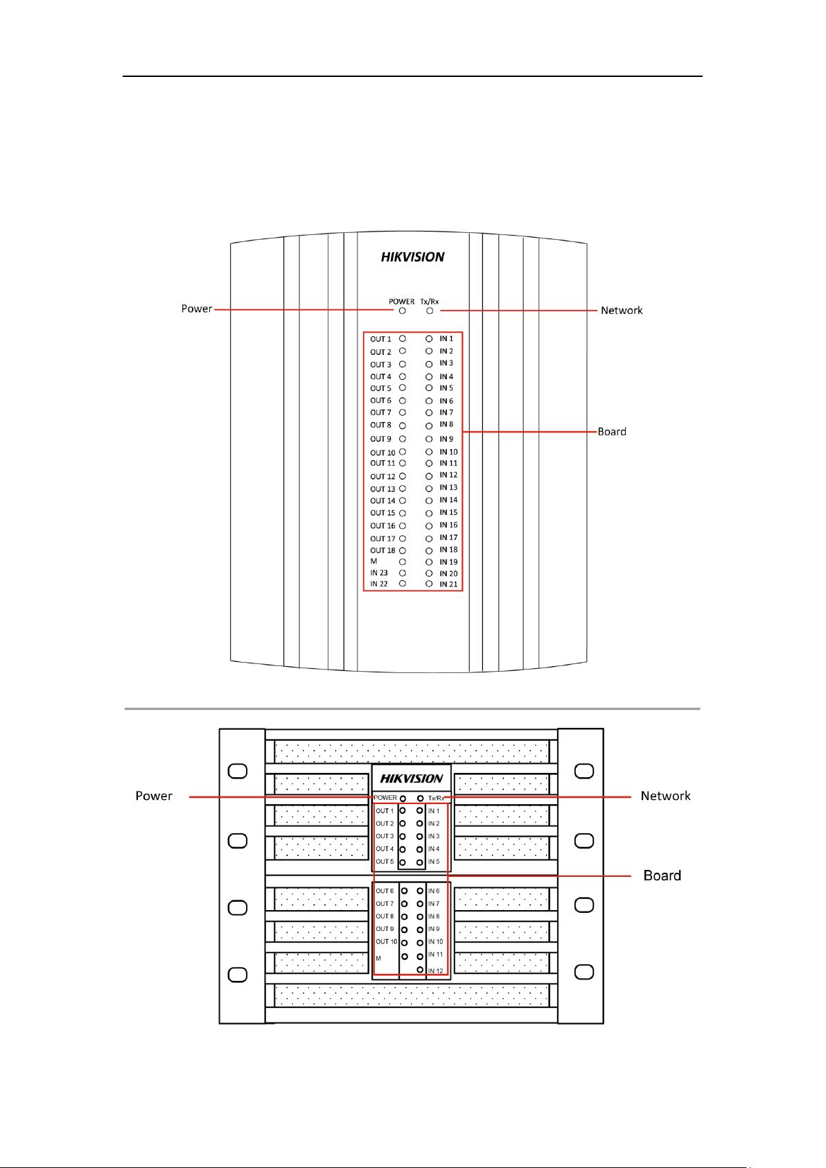
1.4.1 Front Panel
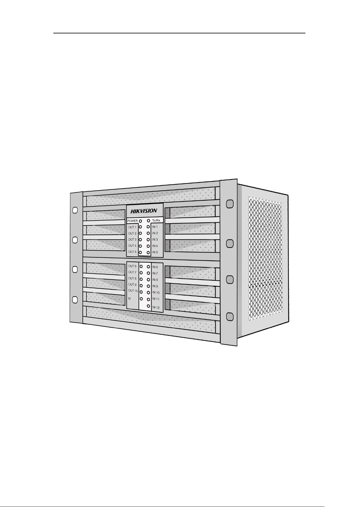
Figure 1. 2 Front Panel of DS-C10S-S41/E
Figure 1. 3 Front Panel of DS-C10S-S22/E
9
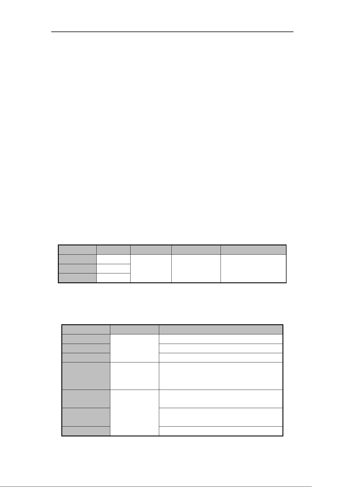
Page 11
DS-C10S Series Video Wall Controller User Manual
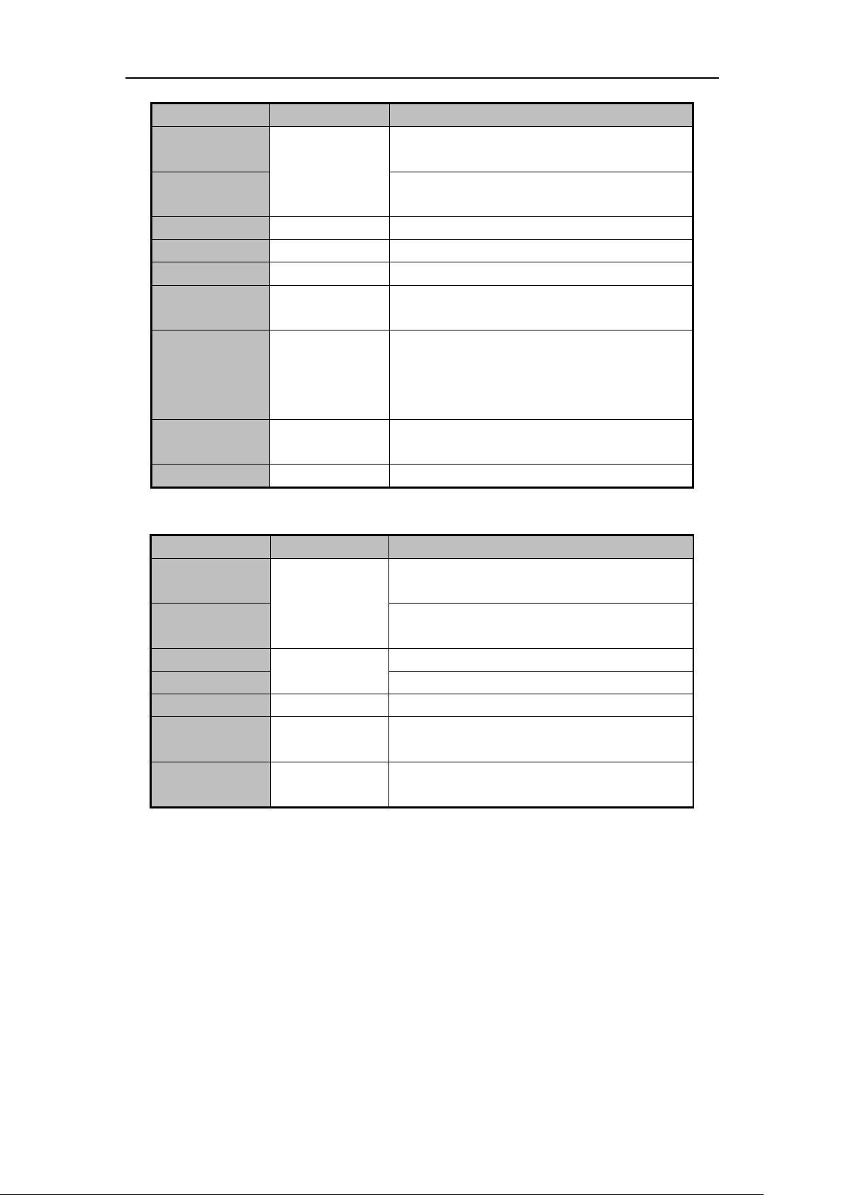
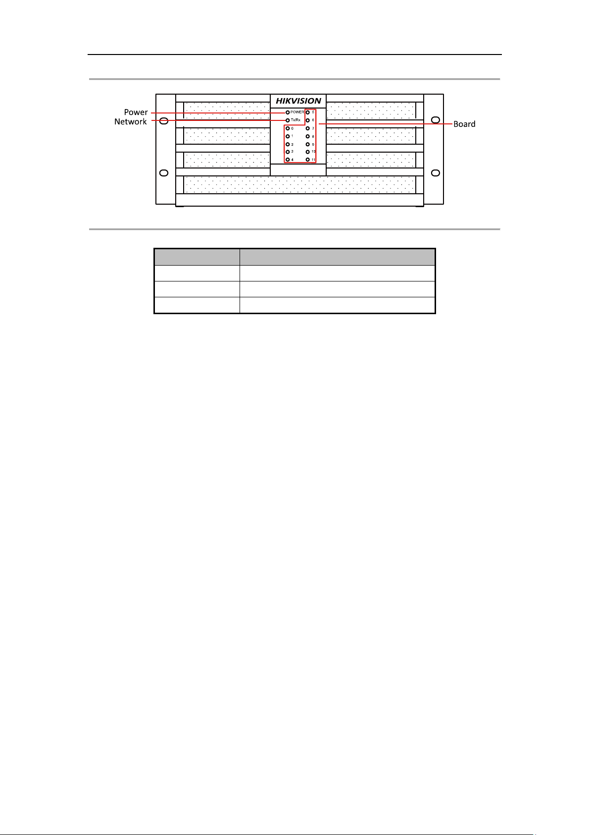
Name
Description
Power Indicator
Indicates the status of power supply.
Network Indicator
Indicates the status of network connection.
Board Indicator
Indicates the status of board status.
Figure 1. 4 Front Panel of DS-C10S-S11/E
Table 1. 1 Front View Description
10
Page 12
DS-C10S Series Video Wall Controller User Manual
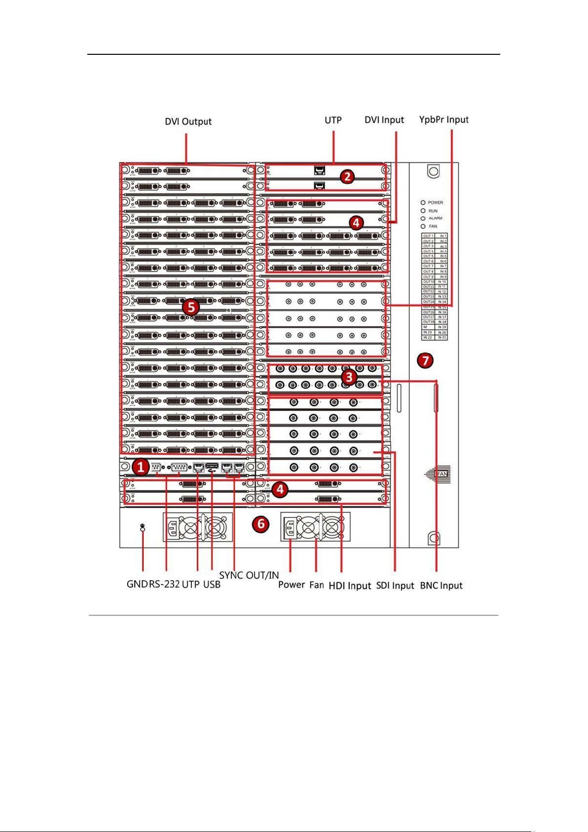
1.4.2 Rear Panel
Figure 1. 5 Rear View of DS-C10S-S41/E
11
Page 13
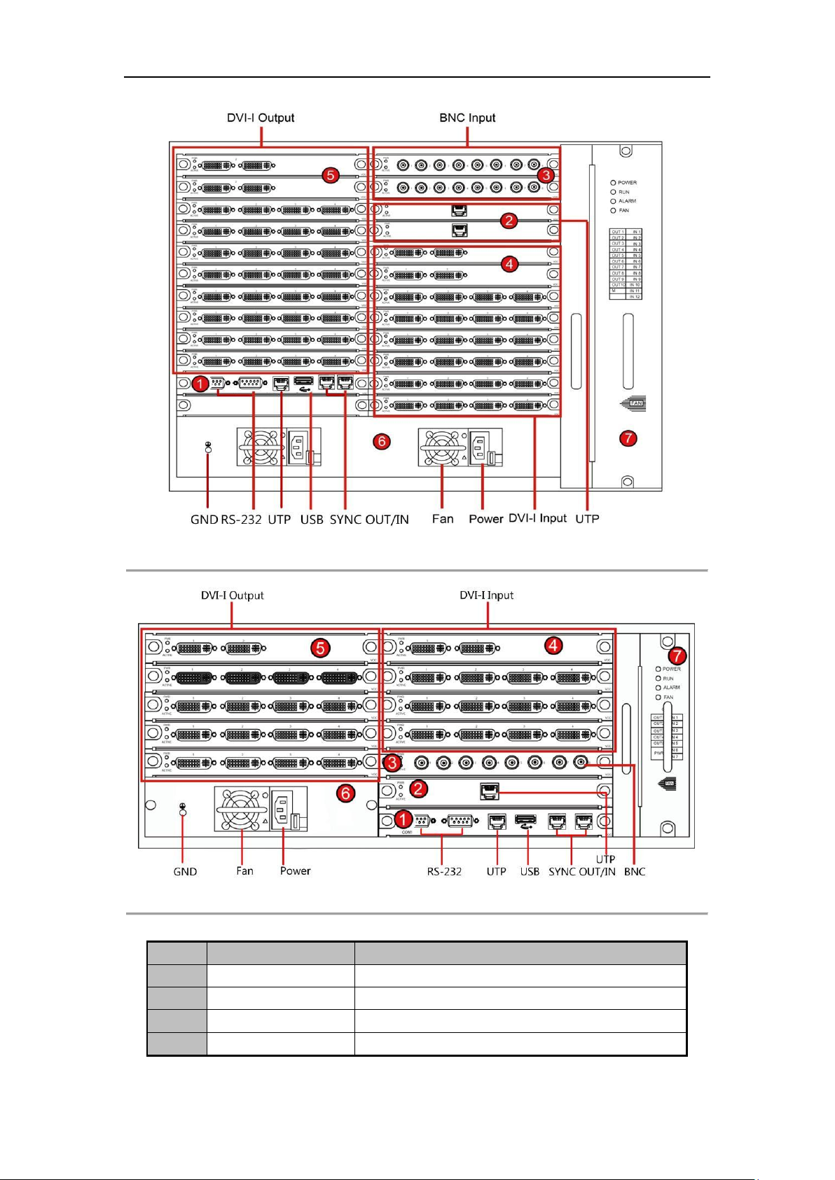
DS-C10S Series Video Wall Controller User Manual
No.
Name
Description
1
Motherboard
Includes USB, UTP, and RS-232 interfaces.
2
Network Decoding Board
With UTP interfaces.
3
BNC Input Board
With BNC Input interfaces.
4
DVI-I Input Board
With DVI-I input interfaces.
Figure 1. 6 Rear Panel of DS-C10S-S22/E
Figure 1. 7 Rear Panel of DS-C10S-S11/E
Table 1. 2 Interface Description of Rear View
12
Page 14
DS-C10S Series Video Wall Controller User Manual
No.
Name
Description
5
DVI-I Output Board
With DVI-I output interfaces.
6
Power
Contains the physical power switch, power plug and power
supply fan.
Ensure that the site's AC power supply is stable and
within the rated voltage of the unit. If the site's AC power is
likely to have spikes or power dips, use power line
conditioning or an uninterrupted power supply (UPS).
7
Fan
Hot-swap may cause damage to the fan. There are four
indicators on the fan board. They are the POWER, RUN,
ALARM and FAN. The RUN and POWER shows the working
status of the fan, and the ALARM shows an abnormal status
of the fan.
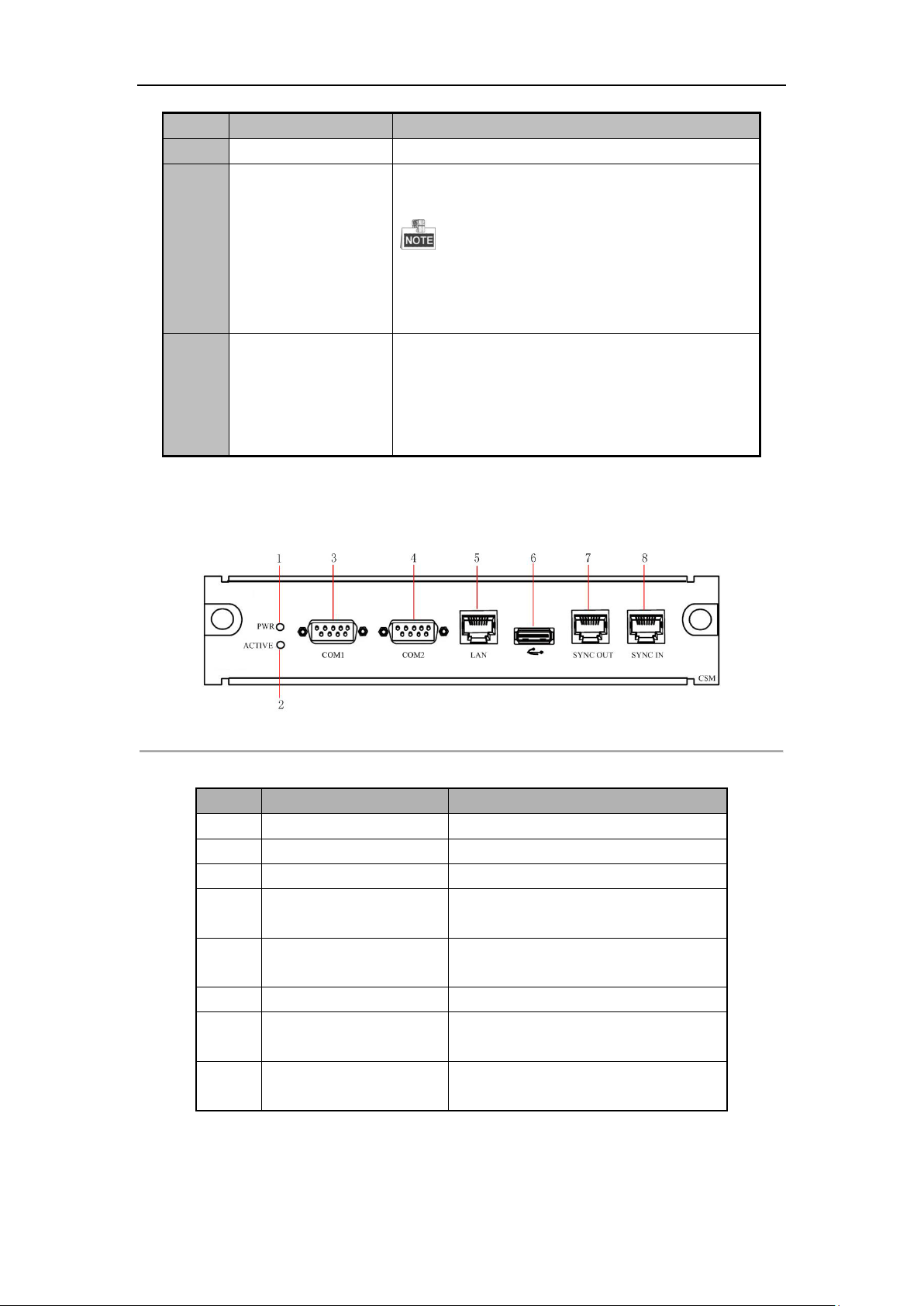
No.
Name
Description
1
Power Indicator
When power on, the indicator is steady green.
2
Working Status Indicator
Flickering when the board is working.
3
COM 1
Debugging interface.
4
COM 2
Control interface for screen control, matrix
linkage, and keyboard.
5
Network Interface
Interface for network transmission and
control.
6
USB Interface
Reversed interface.
7
Synchronization Output
Input interface for synchronization signal.
(reserved)
8
Synchronization Input
Input interface for synchronization signal.
(reserved)
1.4.3 Motherboard
Figure 1. 8 Rear Panel of Motherboard
Table 1. 3 Motherboard Description
13
Page 15
DS-C10S Series Video Wall Controller User Manual
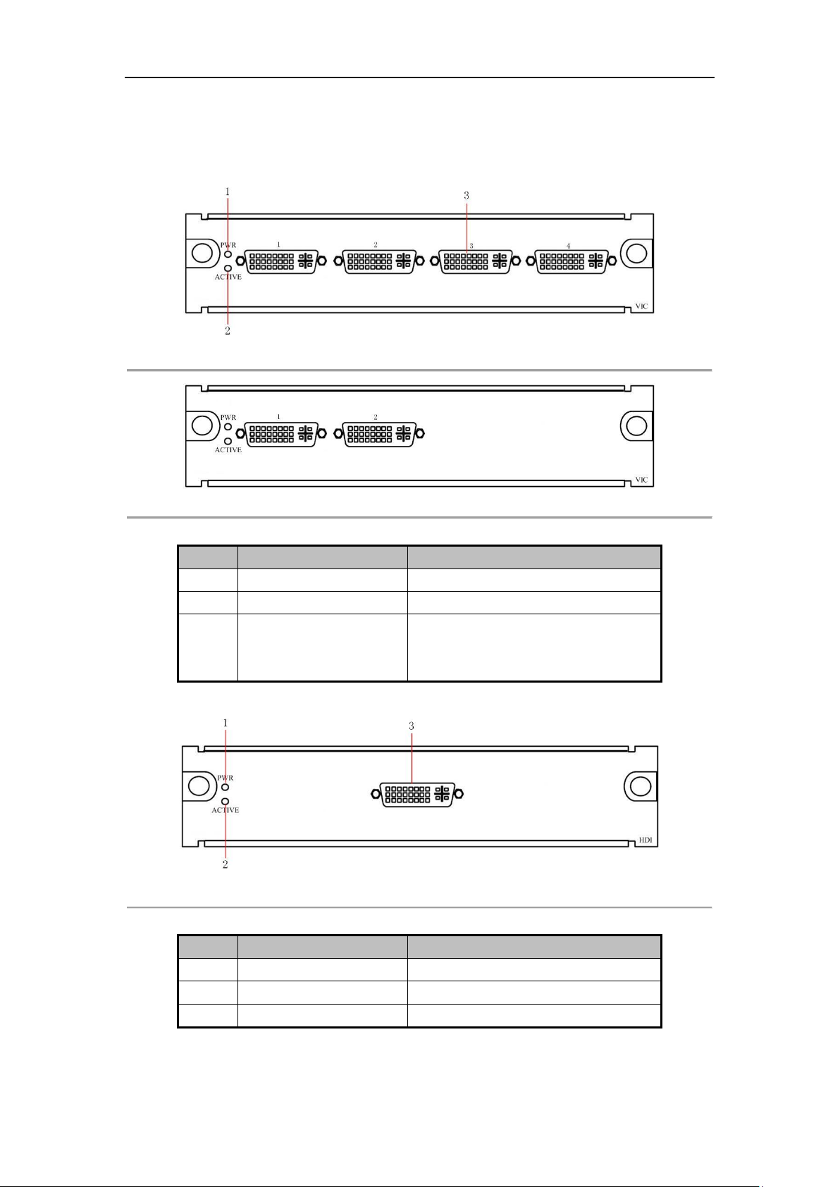
No.
Name
Description
1
Power Indicator
When power on, the indicator is steady green.
2
Working Status Indicator
Flickering when the board is working.
3
DVI-I Input Connector
DVI-I Input Connector (If you want to connect
the VGA or HDMI signal, the adaptor is
needed.)
No.
Name
Description
1
Power Indicator
When power on, the indicator is steady green.
2
Working Status Indicator
Flickering when the board is working.
3
DVI-I Input Connector
DVI-I Input Connector.
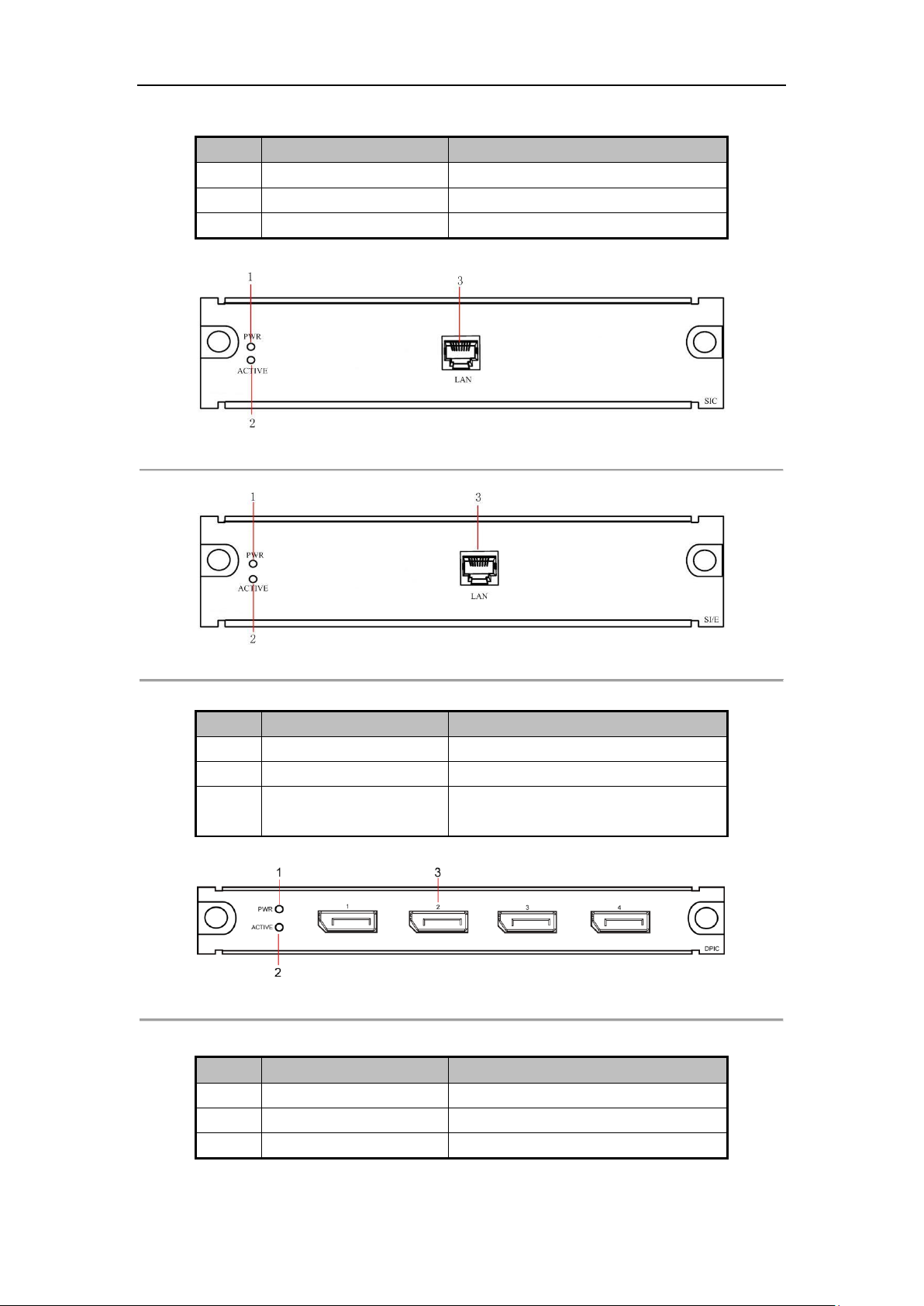
1.4.4 Input Module
DVI Input Board
Figure 1. 9 Rear Panel of DS-C10S-DI/4 and DS-C10S-DI/E
Table 1. 4 Interface Description of DVI Input Board
DVI Dual Link Input Board
Figure 1. 11 Rear Panel of DS-C10S-HDI/1
Table 1. 5 Interface Description of DVI Dual link Input Board
Figure 1. 10 Rear Panel of DS-C10S-DI/2
14
Page 16
DS-C10S Series Video Wall Controller User Manual
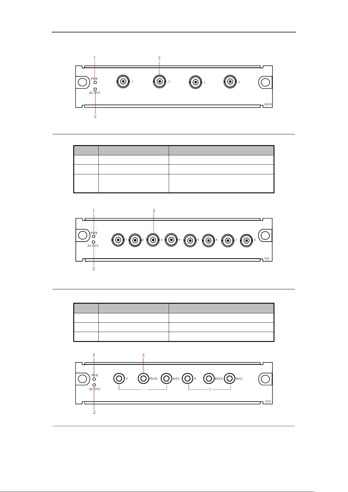
No.
Name
Description
1
Power Indicator
When power on, the indicator is steady green.
2
Working Status Indicator
Flickering when the board is working.
3
BNC Input Connector
BNC input connector for SDI high definition
digital signal.
No.
Name
Description
1
Power Indicator
When power on, the indicator is steady green.
2
Working Status Indicator
Flickering when the board is working.
3
BNC Input Connector
BNC input connector for BNC analog signal.
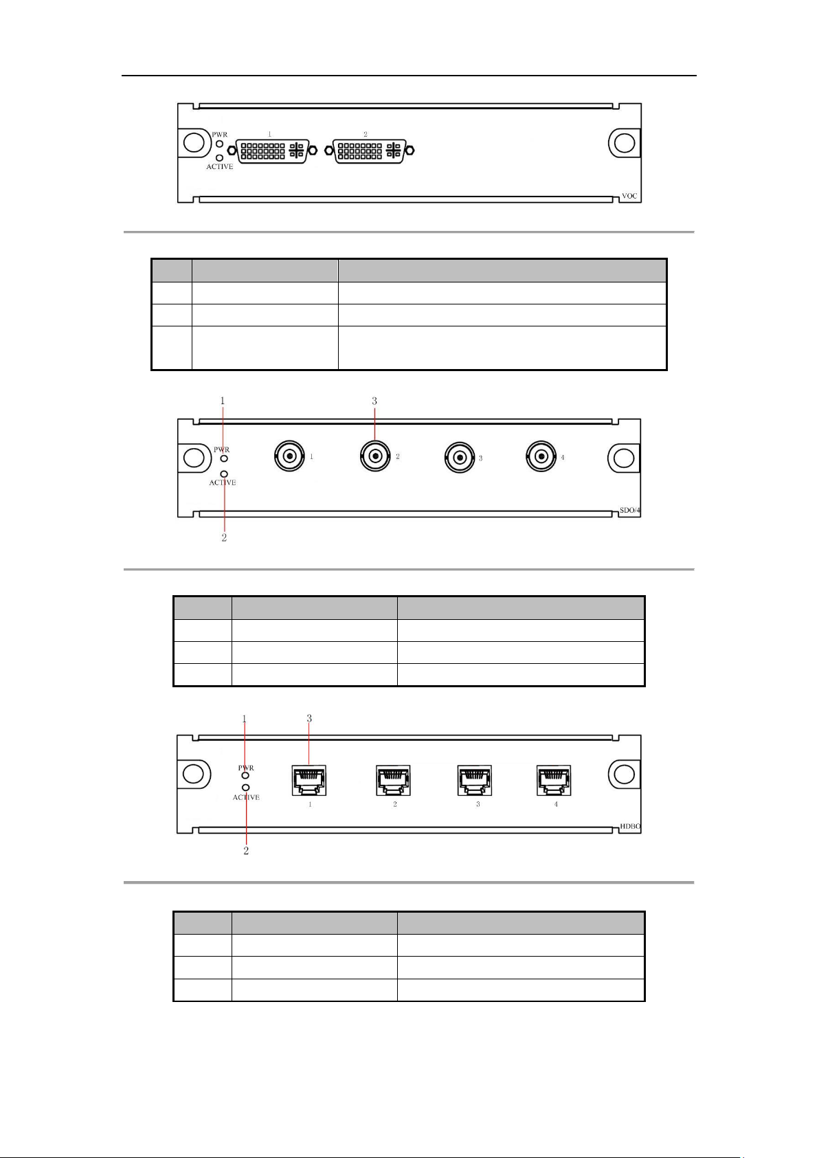
SDI Input Board
Figure 1. 12 Rear Panel of DS-C10S-SDI/4
Table 1. 6 Interface Description of SDI Input Board
BNC Input Board
YPbPr Input Board
Figure 1. 13 Rear Panel of DS-C10S-BI/8
Table 1. 7 Interface Description of BNC Input Board
Figure 1. 14 Rear Panel of DS-C10S-YI/2
15
Page 17
DS-C10S Series Video Wall Controller User Manual
No.
Name
Description
1
Power Indicator
When power on, the indicator is steady green.
2
Working Status Indicator
Flickering when the board is working.
3
YPbPr Input Connector
RCA connector for YPbPr signal.
No.
Name
Description
1
Power Indicator
When power on, the indicator is steady green.
2
Working Status Indicator
Flickering when the board is working.
3
Network Interface
The decoding board needs to be connected to
the network independently.
No.
Name
Description
1
Power Indicator
When power on, the indicator is steady green.
2
Working Status Indicator
Flickering when the board is working.
3
DP Input Connector
DP input connector for DP signal.
Table 1. 8 Interface Description of YPbPr Input Board
Network Decoding Board and Enhanced Network Decoding Board
Figure 1. 15 Rear Panel of DS-C10S-SI
Figure 1. 16 Rear Panel of DS-C10S-SI/E
Table 1. 9 Interface Description of Network and Enhanced Network Decoding Board
DP (DisplayPort) Input Board
Figure 1. 17 Rear Panel of DS-C10S-DPI/4
Table 1. 10 Description of DP Input Board
16
Page 18

DS-C10S Series Video Wall Controller User Manual
No.
Name
Description
1
Power Indicator
When power on, the indicator is steady green.
2
Working Status Indicator
Flickering when the board is working.
3
HDTVI Input Connector
BNC input connector for BNC signal.
No.
Name
Description
1
Power Indicator
When power on, the indicator is steady green.
2
Working Status Indicator
Flickering when the board is working.
3
HDMI Input Connector
HDMI input connector for HDMI signal.
HDTVI Input Board
Figure 1. 18 Rear Panel of DS-C10S-TVI/4
Table 1. 11 Description of HDTVI Input Board
HDMI Input Board
Figure 1. 19 Rear Panel of DS-C10S-HI/E
Table 1. 12 Description of HDMI Input Board
1.4.5 Output Module
DVI Output Board
Figure 1. 20 Rear Panel of DS-C10S-DO/4
17
Page 19
DS-C10S Series Video Wall Controller User Manual
No.
Name
Description
1
Power Indicator
When power on, the indicator is steady green.
2
Working Status Indicator
Flickering when the board is working.
3
DVI-I Output Connector
DVI-I output connector (If you want to connect the VGA
output, the adaptor is needed.) HDMI output is supported.
No.
Name
Description
1
Power Indicator
When power on, the indicator is steady green.
2
Working Status Indicator
Flickering when the board is working.
3
BNC Output Connector
BNC output connector.
No.
Name
Description
1
Power Indicator
When power on, the indicator is steady green.
2
Working Status Indicator
Flickering when the board is working.
3
HDBaseT Interface
HDBaseT output connector.
Figure 1. 21 Rear Panel of DS-C10S-DO/2
Table 1. 13 Interface Description of DVI Output Board
SDI Output Board
Table 1. 14 Interface Description of SDI Output Board
HDBaseT Output Board
Table 1. 15 Interface Description of HDBaseT Output Board
Figure 1. 22 Rear Panel of DS-C10S-SDO/4
Figure 1. 23 Rear Panel of DS-C10S-HDBO/4
18
Page 20

DS-C10S Series Video Wall Controller User Manual
Module
DS-C10S-S11/E
DS-C10S-S22/E
DS-C10S-S41/E
Hardware
Slot No.
11 (6 × Input & 5 ×
Output)
22 (12 × input & 10 ×
output)
41 (23 × input & 18 ×
output)
Motherboard
(DS-C10S-MSU)
Network
1; 10M/100M/1000M self-adaptive Ethernet interface
USB
1 × USB2.0 (Reserved)
RS-232
2
Network Decoding
Board
(DS-C10S-SI)
Decoding
Performance
2-ch@5MP; 4-ch@1080p; 8-ch@720p; 16-ch@D1.
Enhanced Network
Decoding Board
(DS-C10S-SI/E)
Decoding
Performance
2-ch@8MP (low frame rate), 2-ch @6MP (full frame rate), 2-ch @5MP (full
frame rate), 8-ch @1080P, 16-ch @720P, or 32-ch @D1.
BNC Input Board
(DS-C10S-BI)
Input
8 × BNC interface; PAL/NTSC self-adaptive.
VGA Input Board
(DS-C10S-VI/2,
DS-C10S-VI/4)
Input
4/2 × VGA interface
RGB
Resolution
HD15 interface (DVI-HD15 adaptor is needed) 720P@60Hz, 1024×768@60Hz,
1024×768@75Hz, 1280×1024@60Hz, 1280×1024@75Hz, 1366x768@60Hz,
1400x1050@60Hz, 1080P@60Hz, UXGA@60Hz, 1920×1200@60Hz.
DVI Input Board
(DS-C10S-DI/2,
DS-C10S-DI/4,
DS-C10S-DI/E)
Input
DS-C10S-DI/4, DS-C10S-DI/E: 4 × DVI interface.
DS-C10S-DI/2: 2 × DVI interface.
DVI
Resolution
720P@50Hz, 720P@60Hz, 1024×768@60Hz, 1024×768@75Hz,
1280×1024@60Hz, 1280×1024@75Hz, 1366x768@60Hz, 1400x1050@60Hz,
1080P@50Hz, 1080P@60Hz, UXGA@60Hz, 1920×1200@60Hz.
DVI Dual Link Input
Board
(DS-C10S-HDI/1)
Analog Signal
Input
Resolution
2048×1536@30Hz, 2560×1440@30Hz, 2560×1600@30Hz, 2560×2048@30Hz,
2800×2100@30Hz, 3072×2304@30Hz,3840×2160@30Hz, 4088×4088@15Hz.
HDMI Input Board
(DS-C10S-HI/4,
DS-C10S-HI/2,
DS-C10S-HI/E)
Input
DS-C10S-HI/4 and DS-C10S-HI/E: 4 × HDMI interface.
DS-C10S-HI/2: 2 × HDMI interface.
(The adaptor for switch DVI to HDMI is needed.)
HDMI
Resolution
DS-C10S-HI/4, DS-C10S-HI/2: 720P@50Hz, 720P@60Hz, 1024×768@60Hz,
1024×768@75Hz, 1280×1024@60Hz, 1280×1024@75Hz,
1366x768@60Hz, 1400x1050@60Hz, 1080P@50Hz, 1080P@60Hz,
UXGA@60Hz, 1920×1200@60Hz.
DS-C10S-HI/E: 720P@50Hz, 720P@60Hz, 1024×768@60Hz,
1024×768@75Hz, 1280×1024@60Hz, 1280×1024@75Hz,
1366x768@60Hz, 1400x1050@60Hz, 1080P@50Hz, 1080P@60Hz,
UXGA@60Hz, 1920×1200@60Hz, 3840×2160@30Hz, and
3840×2160@25Hz (3840×2160@30Hz and 3840×2160@25Hz are only
support by No. 1 and 3 interfaces)
SDI Input Board
(DS-C10S-SDI)
Input
4 × BNC interface
SDI Analog
Signal Input
Resolution
720P@25Hz, 720P@30Hz, 720P@50Hz, 720P@60Hz, 1080P@25Hz,
1080P@30Hz.
YPbPr Input Board
Input
2 × RCA interface
1.5 Specification
19
Page 21

DS-C10S Series Video Wall Controller User Manual
Module
DS-C10S-S11/E
DS-C10S-S22/E
DS-C10S-S41/E
(DS-C10S-YI)
Resolution
480I@60Hz, 480P@60Hz, 576I@50Hz, 576P@50Hz, 720P@50Hz, 720P@60Hz,
1080I@50Hz, 1080I@60Hz.
DP Input Board
(DS-C10S-DPI/4)
Input
4 × DP interface
Resolution
1024×768@60Hz, 1024×768@75Hz, 1280×720@50Hz, 1280×720@60Hz,
1280×1024@60Hz, 1280×1024@75Hz, 1366×768@60Hz, 1400×1050@60Hz,
1600×1200@60Hz, 1920×1080@50Hz, 1920×1080@60Hz, 1920×1200@60Hz,
3840×2160@30Hz, and 3840×2160@25Hz (3840×2160@30Hz and
3840×2160@25Hz are only support by No. 1 and 3 interfaces)
HDTVI Input Board
(DS-C10S-TVI/4)
Input
4 × TVI interface
Resolution
1280×720@25Hz, 1280×720@30Hz, 1280×720@50Hz, 1280×720@60Hz,
1920×1080@25Hz, 1920×1080@30Hz
VGA Output Board
(DS-C10S-VO)
Output
4/2 × VGA interface
RGB
Resolution
HD15 interface (DVI-HD15 adaptor needed); Resolution: 1024×768@60Hz,
1024×768@75Hz, 1360×768@60Hz, 1080P@60Hz, 1400×1050@60Hz,
1920×1200@60Hz, 720P@60Hz.
DVI Output Board
(DS-C10S-DO)
Output
4/2 × DVI interface
DVI
Resolution
1024×768@60Hz, 1024×768@75Hz, 1360×768@60Hz, 1080P@60Hz,
1400×1050@60Hz, 1920×1200@60Hz, 720P@60Hz.
SDI Output Board
(DS-C10S-SDO/4)
Output
4 × BNC interface
SDI
Resolution
720P@50Hz, 720P@60Hz, 1080P@50Hz, 1080P@60Hz.
HDMI Output Board
(DS-C10S-HO/2)
Output
2 × DVI interface
HDMI
Resolution
1024×768@60Hz, 1024×768@75Hz, 1360×768@60Hz, 1080P@60Hz,
1400×1050@60Hz, 1920×1200@60Hz, 720P@60Hz.
HDBaseT Output
Board
(DS-C10S-HDBO/4)
Output
4 × RJ45 interface
HDBaseT
Resolution
1024×768@60Hz, 1024×768@75Hz, 1360×768@60Hz, 1080P@60Hz,
1400×1050@60Hz, 1920×1200@60Hz, 720P@60Hz.
Other
Power Supply
100 to 240 VAC, 50/60Hz
A build-in power supply
Build-in redundant power supply
Consumption
≤ 250W (full-loaded)
≤ 450W (full-loaded)
≤ 800W (full-loaded)
Working
Temperature
0° C to 50° C (32° F to 122° F )
Working
Humidity
10 to 90% (non-condensing)
Chassis
Standard 4U chassis
Standard 8U chassis
Standard 13U chassis
Dimension
(D×H×W)
352×177×442.4 mm
(13.9×7×17.4")
352×354×442.4 mm
(13.9×13.9×17.4")
417×576.6×442.4mm
(16.4×27.7×17.4")
Weight
≤20KG (full-loaded)
≤35kg (full-loaded)
≤50kg (full-loaded)
20
Page 22

DS-C10S Series Video Wall Controller User Manual
Chapter 2 Overview of Client Software
The C10S series large-screen controller must be controlled and managed by the iVMS-4200 client software.
iVMS-4200 is a versatile video management software for embedded DVR (Digital Video Recorder), H-DVR (Hybrid
Digital Video Recorder), NVR (Network Video Recorder), IP camera, IP Dome, PC-NVR, decoding device and
compression card. It provides the multiple functionality, including live view, remote configuration, record files
storage, remote playback, downloading, log search, etc.
2.1 Features
A user friendly GUI (Graphical User Interface). You can access to target interface with least steps.
Centralized management for small-scale decentralized system.
Up to 50 users, with 3 levels permission (super user, administrator and operator), can be added.
Configure user permission in batch and retrieve password by super user.
Compatible to configuration files generated by customized tools.
Hide menu you do not need thus to save limited space on screen.
Support channel management.
A simplified switch method for multi-screen and signal screen.
2.2 Working Environment
Operating System: Microsoft Windows 7 / Windows Server 2008 (32/64-bit operating system); Windows Server
2003 or Windows XP (32-bit operating system).
CPU: Intel Pentium IV 3.0 GHz or models above.
Memory: 1G or above.
Displayer: 1024 × 768 or above.
The software does not support 64-bit operating system; the above mentioned 64-bit operating system
refers to the system which supports 32-bit applications as well.
2.3 Performance
Up to 256 controllers can be managed.
Many controllers can be added to the software; however, only one controller can be controlled at a time.
One controller can be connected by 320 clients at a time.
A higher hardware configuration is needed when viewing multiple channels or HD (High Definition)
images.
21
Page 23

DS-C10S Series Video Wall Controller User Manual
Chapter 3 Client Software Installation and
Uninstallation
3.1 Installing Software
Double-click the setup program to pop up InstallShield Wizard. Follow the steps and complete the installation.
Figure 3. 1 Software Installation
3.2 Uninstalling Software
Option 1:
Double-click the setup program again to enter uninstall menu. And follow the prompt to uninstall the iVMS-4200.
Option 2:
Enter Windows Start Menu and select uninstall iVMS-4200. Then follow the prompt to uninstall the iVMS-4200.
Figure 3. 2 Software Uninstallation
22
Page 24

DS-C10S Series Video Wall Controller User Manual
3.3 User Registration and Login
3.3.1 Registration
For the first time to use iVMS-4200 software, you need to register a super user for login.
Steps:
1. Input the user name, password and confirm password.
2. Optionally, you can check the checkbox of Auto-login to log in automatically when running software next
time.
3. Click Register to save the user and log in.
Figure 3. 3 Registration
User name and password can’t be empty and should not contain the following characters: / \ : * ? \ " < > |.
The valid character of user name includes numberical (0 ~9) and letters (a ~ z, A ~ Z).
The blank character before or behind the user name will be automatically deleted.
The valid length of password for super user ranges from 6 to 16 characters. The valid length of password for
other users should be less than 16 characters.
Password cannot be copied and pasted.
3.3.2 Login
Steps:
1. Input the user name and password.
2. Optionally, check the checkbox of Auto-login to log in automatically when running software next time.
3. Click Login to log in.
Figure 3. 4 Login
23
Page 25

DS-C10S Series Video Wall Controller User Manual
3.4 Using the Wizard for Basic Configuration
Purpose:
After login for the first time, the setup wizard pops up automatically. It can walk you through some basic settings
of the video wall.
Figure 3. 5 Start Wizard
Steps:
1. Click Open Wizard to enter Add Video Wall interface.
If you don’t want to use the setup wizard at the moment, click to exit. You can also use the Setup
Wizard next time by leaving the Do Not Show Next Time unchecked.
Figure 3. 6 Add Video Wall Interface
2. Draw a video wall by clicking and dragging the mouse to select the rows and columns, or inputting values in
Row and Column text fields.
3. Input the video wall name in Name text field.
4. Click Next to save the settings and enter Add Device interface.
24
Page 26

DS-C10S Series Video Wall Controller User Manual
Figure 3. 7 Add Devices Interface
5. You can add, modify and delete devices here. Three types of devices can be added, including Video Wall
Controller, MVC (Mulit-function Video Center), and decoder.
Add Devices
1) Click Add to pop up adding interface.
2) Select Adding Mode as IP/Domain, IP Segment or HiDDNS. We take adding via IP/Domain as an
example.
3) Input Nickname, Address, Port, User Name, Password and Group in the text fields.
4) Click Add to add the device(s).
Figure 3. 8 Adding a Device
Modify Devices
1) Click to select an added device and click Modify.
2) Edit the information.
3) Click Modify to save the changes.
Delete Devices
Click to select an added devices and click Delete to delete it.
Show Output No.
1) Click the Show Output No..
25
Page 27

DS-C10S Series Video Wall Controller User Manual
2) Select the device(s) you need to display the output No..
3) Click Show to enable the function. Thus the output No. of the selected device(s) will be shown in the
video wall.
The function is only supported by video wall controller.
Figure 3. 9 Show Output No.
6. After the devices are configured, click Next to enter Link Decoding Output settings interface.
Figure 3. 10 Link Decoding Output
7. You can adjust the output window of the added video wall controller.
1) Click Cancel All to clear the default settings. Or select a window and click Cancel to clear the linkage
between the output and the window.
2) Select and hold a decoding output in the Decoding Output list and drag it to a window to link the
output to the window.
26
Page 28

DS-C10S Series Video Wall Controller User Manual
Region
Name
Description
1
Menu Bar
Menus include File, System, View, Tool, and Help.
2
Quick Launch Bar
Video Wall, Screen Control, Device Management, Account Management,
and System Configuration.
3
Maintenance and
Management
Area
Configure and manage the video wall controller, and the software.
4
Notification Bar
Display information of current window and preview information list; View
alarm channel information.
5
Configuration List
Manage Signal Source, Camera, Scene, Plan and PTZ.
Detailed Description of Menu Bar
(1)
File
Open log file save in computer and exit from the software.
(2)
System
Lock software, switch user, and import/export system configuration file.
(3)
View
Enter Video wall, Screen Control, Device Management, Account
Management, and System Configuration interface.
(4)
Tool
Enter Log Search, Video Wall Linkage, and Device Arming Control interface.
(5)
Help
Open video wall wizard, open user manual, view software version, and
switch language.
3) Repeat the above steps to configure for other outputs.
8. Click Done to save the settings.
3.5 GUI Introduction
Figure 3. 11 Software Interface
Table 3. 1 Table of Description
27
Page 29

DS-C10S Series Video Wall Controller User Manual
Chapter 4 Video Wall Client Management
4.1 Account Management
Purpose:
In default situation, there will be only one super user, registered when logging in. Besides the super user, you can
add 50 users, including administrator and operator, with different permission.
Steps:
1. Click Account Management in the Quick Launch Bar.
Figure 4. 1 Account Management Interface
2. Click Add User button to enter Add User interface.
28
Page 30

DS-C10S Series Video Wall Controller User Manual
Figure 4. 2 Add User
3. Select User Type as Administrator or Operator.
4. Input User Name, Password, Confirm Password, Remark and specify user permission by checking or
unchecking corresponding checkbox. Or you can click Copy from to copy from other user.
User Name cannot contain: \ / : * ? " < > |.
The length of password should not less than 6 bits.
5. Click Save to add the account.
6. Optionally, click Edit User to modify its parameters or click Delete User to remove it.
Super user cannot be deleted.
4.2 System Configuration
The frequently-used parameters, including the log expired time, file saving path, etc., can be set.
4.2.1 General Settings
Steps:
1. Click System Configuration in the Quick Launch Bar to enter System Configuration interface.
29
Page 31

DS-C10S Series Video Wall Controller User Manual
Parameters
Description
Auto-login
Log in the client software automatically.
Keep Log files for
The time for keeping the log files, once exceeds, the files will be
deleted. A Month, A Week, Half A Month and 6 Months are selectable.
The default time is A Month.
Automatic Time Synchronization
Adjust the time automatically at a specified time point.
Automatic Time Synchronization
Check the checkbox to enable the function.
Figure 4. 3 System Configuration
3. Configure the general parameters. For details, see Table 4. 1General Parameters.
Table 4. 1 General Parameters
4.2.2 File Saving Path Settings
Purpose:
The video files of manual recording, the captured pictures and the system configuration files are stored on the
local PC. The saving paths of these files can be set.
Steps:
1. Click System Configuration in the Quick Launch Bar to enter System Configuration interface.
2. Click the icon and select a local path for the files.
3. Click Save to save the settings.
You need to reboot software to activate the settings.
30
Page 32

DS-C10S Series Video Wall Controller User Manual
4.3 Device Management
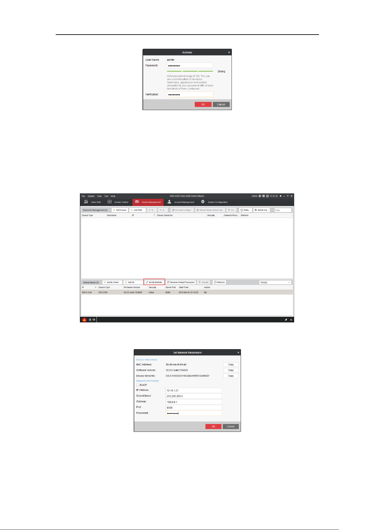
4.3.1 Setting Admin Password for a Device
Purpose:
You are required to activate the video wall controller first by setting a strong password for it before you can use
the video wall controller.
Three types of devices can be added, including Video Wall Controller, MVC (Mulit-function Video Center),
and decoder.
You are required to modify the password of old version controller to a strong one.
Before you start:
Ensure your computer is in the same network segment with the controller.
Steps:
1. Click to select Device Management in the Quick Launch Bar to enter Device Management interface.
2. Select an inactive device and click Activate to enter Activation interface.
Figure 4. 4 Activating Video Wall Controller
3. Create a password and input the password into the password field, and confirm the password.
STRONG PASSWORD RECOMMENDED– We highly recommend you create a strong password
of your own choosing (using a minimum of 8 characters, including upper case letters, lower
case letters, numbers, and special characters) in order to increase the security of your
product. And we recommend you reset your password regularly, especially in the high
security system, resetting the password monthly or weekly can better protect your product.
31
Page 33
DS-C10S Series Video Wall Controller User Manual
Figure 4. 5 Creating Password
4. Click OK to save the password and activate the controller.
4.3.2 Adding a Device
Steps for Latest Version Controller:
1. Select the activated controller and click Modify Netinfo to set the IP address of the controller.
Figure 4. 6 Modifying Network Parameters
2. Input the IP address, Gateway and Password, and click OK to save the IP address.
Figure 4. 7 Device Management Interface
3. Click the Add to Client button and input the Nickname for the controller.
32
Page 34

DS-C10S Series Video Wall Controller User Manual
Figure 4. 8 Adding Device Interface
4. Click Add to add it.
Steps for Old Version Controller:
1. Click the Add Device button.
Figure 4. 9 Device Management Interface
2. Input the Nickname, Address and Password, and click Add to add it.
Figure 4. 10 Adding Device Interface
3. The Security of added controller will be shown. If the Security is not strong, you are required to modify the
password. For detailed steps, please refer to the chapter System Settings.
STRONG PASSWORD RECOMMENDED– We highly recommend you create a strong password of
your own choosing (using a minimum of 8 characters, including upper case letters, lower case
letters, numbers, and special characters) in order to increase the security of your product. And we
recommend you reset your password regularly, especially in the high security system, resetting
the password monthly or weekly can better protect your product.
Figure 4. 11 Device Management Interface
33
Page 35

DS-C10S Series Video Wall Controller User Manual
Parameters
Description
System
View device information and status, configure general parameters and user, manage
device, adjust time, search and backup log.
Network
Configure general network parameters.
Event
Configure exception linkage method.
Video Display
Upload background picture, configure video effect of input signal, adjust picture
position, and configure background color.
Other
Configure parameter of LED, external decoder, external matrix and background colour.
4.4 Remote Configuration
Purpose:
In remote configuration interface, the parameters of the added controller, including the system, network, etc.,
can be set.
Step:
Click to select an added device and click Remote Configuration to enter Remote Configuration interface.
Figure 4. 12 Remote Configuration Interface
Table 4. 2 Description of Remote Configuration
4.4.1 System Settings
Steps:
1. Click System tab.
2. Configure parameters. For details, refer to Table 4. 3 Description of System.
3. Click Apply to save the settings.
34
Page 36

DS-C10S Series Video Wall Controller User Manual
Parameters
Description
Device Information
View basic information and version.
Working Status
Display the status of controller and its sub board.
General
Configure device name and device number.
Time
Configure time zone, NTP and DST parameters.
System Maintenance
System management and remote upgrade.
Log
Search and back up device logs.
User
Add operators and specify permissions.
Besides the admin account, up to 7 operators can be added.
Admin can add, modify and delete other operators. Operators can only
modify parameters for itself.
Table 4. 3 Description of System
4.4.2 Network Settings
Steps:
1. Click Network tab.
Figure 4. 13 Network Configuration Interface
2. Select NIC Type in the dropdown list.
3. Input IPv4 address, Subnet Mask and Default Gateway.
4. Click Apply to save the settings.
4.4.3 Event Settings
Steps:
1. Click Event tab.
35
Page 37

DS-C10S Series Video Wall Controller User Manual
Figure 4. 14 Event Configuration Interface
2. Enable Link Device Alarm Audio by checking the corresponding checkbox.
3. Click Apply to save the settings.
4.4.4 Video Display Settings
Steps:
1. Click Video Display tab.
Figure 4. 15 Video Display Configuration Interface
2. Select a page of Background Picture Upload, Video Parameters, Picture Adjustment or Background Color
to configure parameters. For details, refer to Table 4. 4 Description of Image Settings.
36
Page 38

DS-C10S Series Video Wall Controller User Manual
Parameters
Description
Picture Upload
Upload local picture as the background of output screen.
Video Parameters
Adjust the video parameters of input signal.
Picture Adjust
Adjust the position of input signal.
Background Color
Set the background color of output.
Parameters
Description
LED
Adjust the Width and Height of LED.
Decoder
Configure the general network parameters of decoder and view decoding board
status.
Decording board needs be independently connected to network. And it does
not decode the stream with frame rate below 1 fps.
Matrix Linkage
Add, edit and delete linkage matrix. The channel of added matrix will be listed in
signal resource of video wall interface and you can display it in video wall.
Before display the matrix signal sources, you need to perform following
operations.
Connect the COM 2 of motherboard to the COM port of matrix.
Configure the board function of motherboard as matrix control.
Signal Source Collage
Collage several signal sources into one. For detailed steps, please refer to
Table 4. 4 Description of Image Settings
4.4.5 Other Settings
Steps:
1. Click Other tab.
Figure 4. 16 Others Configuration Interface
2. Select the page as LED, Decoder, Matrix Linkage, Signal Source Collage or Motherboard Port. For details,
please refer to Table 4. 5 Description of Other Settings.
Table 4. 5 Description of Other Settings
37
Page 39

DS-C10S Series Video Wall Controller User Manual
Parameters
Description
Collaging Signal Sources.
Motherboard Port
Configure the parameter of motherboard serial port.
The Board Function can to be set as Console, Matrix Control, Screen Control
or Keyboard Control according to the serial port usage.
Collaging Signal Sources
Purpose:
You can collage several signal sources into one.
Steps:
1. Enter Signal Source Collage to enter Signal Source Collage interface.
2. Click Add to collage signal source.
Figure 4. 17 Collage Signal Source
3. Input the Collaged Signal Source Name, input the Row × Column in corresponding text fields and select the
Group Name the signal belongs.
4. Drag signal sources need to be collaged into the windows.
IP camera does not support to be collaged.
Ensure each window links to a signal source.
5. Click Apply to save the settings.
6. Put the jointed signal source on the video wall.
4.5 Video Wall Introduction
Click Video Wall in the Quick Launch Bar to enter Video Wall interface. For detailed configuration, you can refer
to Chapter 5 Video Wall Management.
38
Page 40

DS-C10S Series Video Wall Controller User Manual
Video Wall Description
Region
Name
Description
1
Menu List
Manage Signal Source, Camera, Scene, Plan, and PTZ.
2
Window Management Area
Open/close screens and move screens.
3
Window Management Toolbar
Start/stop decoding all signal sources and cameras, close/open
windows, start/stop smart decoding for all signal sources and
cameras, and refreshing live view screens are provided.
4
Advanced Setting Area
Setting area for advanced parameters.
5
Advanced Setting Menu Bar
Configure Window, Virtual LED, Logo and Background Picture.
Screen Control Toolbar Description
Icon
Name
Description
Start All Decoding
Start all the live view of signal sources. Thus to enable live view
of real video wall.
Stop All Decoding
Stop all the live view of signal sources. Thus to disable live view
of real video wall.
Close All Windows
Close all the screens displayed on the video wall.
Start All Smart Decoding
Start smart decoding for all live view signals. Once starts, the
smart information can be viewed in live view.
Stop All Smart Decoding
Stop smart decoding for all live view signals.
Open Window
Draw a window according to your need. The size and position of
the window are adjustable.
Refresh
Refresh the video wall status.
Figure 4. 18 Video Wall Interface
Table 4. 6 Video Wall Description
39
Page 41

DS-C10S Series Video Wall Controller User Manual
Advanced Setting Bar Description
Name
Description
Window
Advanced settings for screens.
Virtual LED
Enable/disable virtual LED and edit virtual LED context.
Logo
Reserved function. Not supported by video wall controller.
Background Picture
Upload and enable/disable background picture.
4.6 Screen Control
Purpose:
In the screen control interface, you can set to turn on or off the monitors, and you can also configure the screen
color and image position.
You are not recommended to configure the screen control without professional instructors.
Before you start:
Connect the COM of screen to the COM2 of motherboard of video wall controller.
Steps:
1. Click Screen Control in Quick Launch Bar to enter Screen Control interface.
2. Drag to select a single window or multiple windows.
3. Select Serial Port No. as COM 2. Thus to specify transmitting port of screen control command.
4. Select Screen Type and Input Source Type according to actual cord connection.
5. Click Save to save the above settings.
6. Adjust Image Parameters and Position Adjustment by clicking or .
7. Click Open Screen or Close Screen to turn on/off the screen. Or click Open All or Close All to turn on/off all
the screens.
Figure 4. 19 Screen Control Interface
40
Page 42
DS-C10S Series Video Wall Controller User Manual
Chapter 5 Video Wall Management
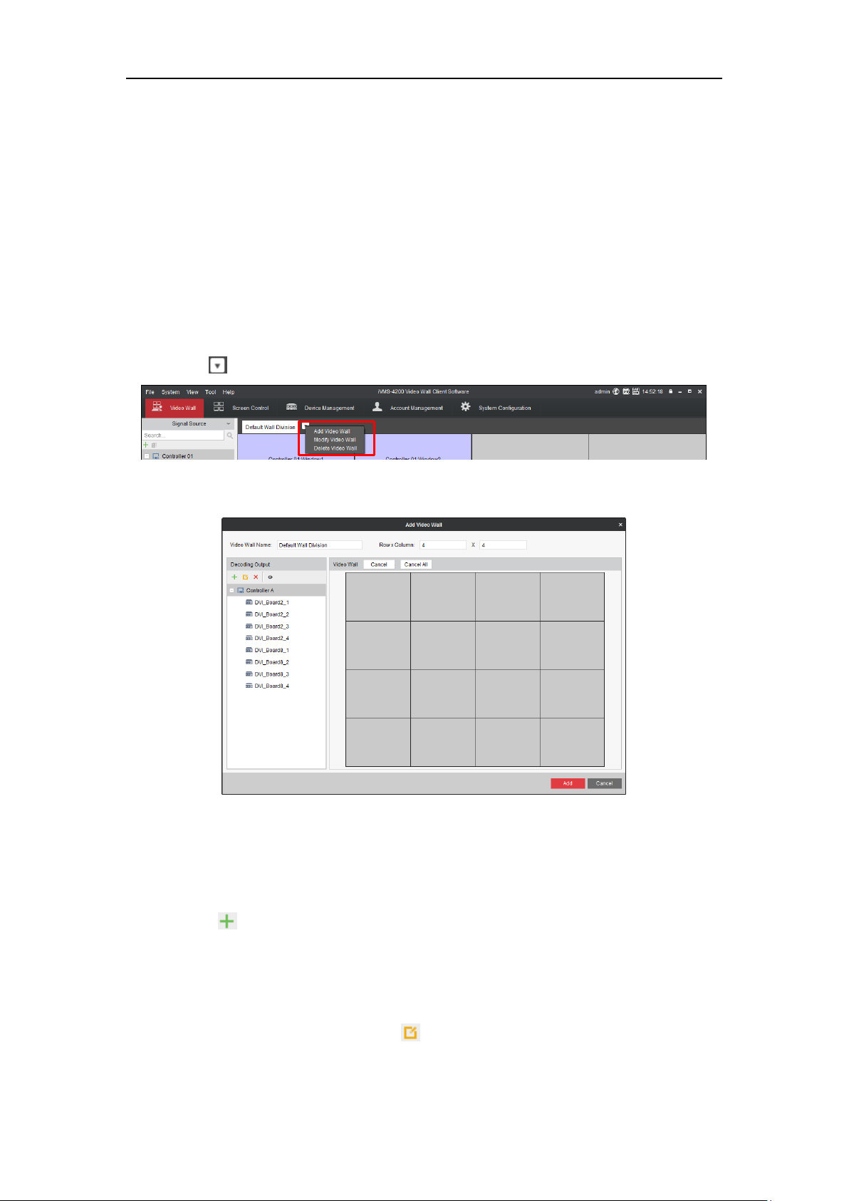
5.1 Adding Video Wall
Purpose:
The software supports adding video wall. You can specify the row, column and decoding outputs of the video
wall.
Steps:
1. Click the icon.
Figure 5. 1 Video Wall Interface
2. Select Add Video Wall to enter configuration interface.
Figure 5. 2 Adding Video Wall Interface
3. Input Video Wall Name in the text field.
4. Input Row and Column value in the respective text fields. Or click a grid and hold to drag a video wall.
5. Optionally, you can add, edit and delete devices.
Add Devices
1) Click to pop up adding interface.
2) Selecting Adding Mode as IP/Domain, IP Segment or HiDDNS.
3) Input the other information in corresponding text fields.
4) Click Add to add the device(s).
Edit Devices
1) Click to select an added device and click .
2) Edit the information.
3) Click Modify to save the changes.
41
Page 43

DS-C10S Series Video Wall Controller User Manual
Delete Devices
Click to select a device and click to delete it.
Show Output No.
1) Click the .
2) Select the device(s) you need to display the output No..
3) Click Show to enable the function. Thus the output No. of the selected device(s) will be shown in the
video wall.
The function is only supported by video wall controller.
6. Select a decoding output and drag it to a window.
7. Repeat Step 6 to link more decoding outputs to the video wall.
8. Click Add to add the video wall.
5.2 Displaying Signals on the Video Wall
The output screen of the controller supports being divided in to 1, 4, 9 or 16 windows. And the input signal can
be displayed in the divided window.
5.2.1 Preview Image
Steps:
1. Positioning the pointer on a signal for 2 to 3 seconds. Then the image will be displayed in a popup window.
2. Move the pointer out of the signal. Then the popup window will disappear.
5.2.2 Putting on Video Wall
Purpose:
A signal source can be put on multiple windows. Ultra HD and 500W signal only support to be displayed in a
single window.
Steps:
1. Put signal sources on the video wall.
Option 1
1) Click to select a window.
2) Double-click a signal source. So the signal will be displayed in the selected screen.
Double-click another signal source will lead to the previous signal be replaced by this one.
3) Repeat the step 1) to 2) to display more signals.
Option 2
1) Click to select a signal source in the signal source list.
2) Click in Window Management Bar and drag to draw a screen in the video wall.
3) Repeat the step 1) to 2) to display more signals.
Repeat step 2) only will display the same signal in multiple windows.
42
Page 44

DS-C10S Series Video Wall Controller User Manual
4) After finishing settings, click again to release the function.
2. Drag a screen to overlap several screens. The screen can be dragged to any position of the video wall.
Figure 5. 3 Video Wall
3. Double-click a screen to fill up the window(s) it overlaps.
4. Positioning the pointer on the screen and click to close the signal source. Or click on Screen
Control Bar to close all the screens.
5.3 Configuring Signal Sources
Purpose:
The added video wall controllers and decoding devices will be listed in the signal source list of Video Wall
interface. You can manage added controllers and add new controllers here.
Besides in the Device Management interface, controller adding function is also provided in Video Wall interface.
Before you start:
Activate the devices need to add. For detailed steps, please refer to 4.3.1 Setting Admin Password for.
Steps:
1. Click button in Signal Source list.
2. Input needed information. For detailed steps, please refer to the step 4 of 3.4 Using the Wizard for Basic
Configuration.
3. Click Add to add the controller.
43
Page 45

DS-C10S Series Video Wall Controller User Manual
Figure 5. 4 Add Device
5.4 Configuring Cameras
5.4.1 Adding a Camera
Purpose:
Besides in the Device Management interface, cameras adding function is also provided in Video Wall interface.
Before you start:
Activate the camera need to add. For detailed steps, please refer to 4.3.1 Setting Admin Password for.
Steps:
1. Click button in Camera list.
2. Input needed information. For detailed steps, please refer to the step 4 of 3.4 Using the Wizard for Basic
Configuration.
3. Click Add to add the controller.
Figure 5. 5 Add a Camera
44
Page 46

DS-C10S Series Video Wall Controller User Manual
5.4.2 Adding a Group
Purpose:
A camera can belong to multiple groups. You can manage its group(s) here.
Steps:
1. Click to pop up group adding interface.
Figure 5. 6 Add Group
2. Input Group Name and select which Parent Area it belongs.
3. Click and select signal sources, and click OK to add them.
4. Optionally, select a signal source, click to rename it or click to delete it.
5. Click OK to add the group.
5.4.3 Modifying the Group
Purpose:
The name and signal resource of a group can be added.
Steps:
1. Click to select a group and click button in Camera list.
2. Click the Signal Source Settings button to enter dialog box.
Figure 5. 7 Signal Source Settings Interface
3. Input a new Name for signal source.
4. Click Configure to save the new name.
45
Page 47

DS-C10S Series Video Wall Controller User Manual
5.5 Creating and Displaying Scene
For one controller, if you expect to get a more convenient way to manage the screen layouts as there are different
video wall layouts need to be set repeatedly, the Scene function may help to ease the burden. With this function,
you are able to save the video wall layout configuration and show it by just clicking on the scene name.
The scene information is saved in the video wall controller. That is to say, you can obtain the scenes of a controller
created by others via adding it.
5.5.1 Creating a Scene
Before you start:
Set the video wall layout first.
Steps:
1. Click the button after Scene in Menu list to show the Scene tab.
Figure 5. 8 Apart of Menu List
2. Click button and input the Name to create a scene.
3. Add a scene.
Adding new scene: select the created scene and click button to save the current video wall
layout to it.
Replace existing scene: click and select the Name you want to save the scene, and click OK to
save it.
Figure 5. 9 Saving Scene As Interface
4. Optionally, you can click to edit a scene name. Or click to delete a selected scene.
5.5.2 Calling a Scene
Purpose:
46
Page 48

DS-C10S Series Video Wall Controller User Manual
You can call a scene which you have created to display it on the video wall.
Steps:
1. Positioning the pointer on a created scene.
Figure 5. 10 Video Wall Interface
2. Click to display the scene on video wall.
The calling scene will be marked as , instead other scenes are marked as .
5.6 Creating and Scheduling Plan
Sometimes, the video wall may be required to do auto-switch for displayed channels, or the screen need to be
turn on/off automatically. Plan is a function to configure the schedule to switch the display of scenes on the video
wall, and it can also automatically switch the screens.
5.6.1 Creating a Plan
Steps:
1. Click the button after Plan in Menu list to show the Plan tab.
2. Click button.
Figure 5. 11 Adding Plan Interface
3. Input Nickname in the text field.
4. Select the Mode as Manual, Auto and Auto-Switch in the dropdown list.
Manual: If you set the Mode of the plan as Manual, you need to start and stop the plan manually. And
plan will only be activated once if you start it. To call the manual plan, you need to right-click on the
plan and click Call on the right-click menu.
47
Page 49

DS-C10S Series Video Wall Controller User Manual
Auto: When setting the Mode of the plan as Auto, you can set the start time and executing times for
the plan. The plan will be activated on the start time and stopped when finish the executing times.
Auto-Switch: The Auto-Switch mode means that not only the times of executing can be set, the days
on which the plan gets activated are also scheduled. The plan will be activated at the time of the day
you configured and stopped after finishing the executing times.
5. Click Plan Task tab to add or edit plan task.
6. Click Add to enter adding task interface.
Figure 5. 12 Operation Interface
7. Select Task Type, Scene, and Screen Type in respective dropdown list. And set the Dwell Time.
8. Click OK to add the task.
9. Repeat the above steps 6 ~ 8 to add more tasks.
10. If the Mode is set as Auto or Auto-Switch, you need to click Parameters tab to configure schedule.
For Auto: set the Start Time and input Execution Times.
For Auto-Switch: set the execution time for each weekday and input Execution Times.
Figure 5. 13 Adding Plan Interface
11. Click OK to save the settings. And the added plan will be displayed in the plan list.
5.6.2 Calling a Plan
Steps:
1. Positioning the pointer on the added plan.
2. Click to call the plan. The calling plan will be marked as , instead other plans are marked as .
3. Click to stop calling.
48
Page 50

DS-C10S Series Video Wall Controller User Manual
5.7 Advanced Settings
If the video wall is required to display a certain background image, such as the picture of the company, you can
configure the background picture on the Display Configuration page, and the virtual LED is also supported.
5.7.1 Configuring Screen Layout
Purpose:
Each output screen can be divided into 1, 4, 9 or 16 screens.
Steps:
1. Click to select a screen.
2. Click on the Advanced Setting Area to pop up screen layout interface.
Figure 5. 14 Advanced Setting Area
3. Click to select a layout. So the window will be divided into the selected layout.
4. Click again and select to restore to single screen.
5.7.2 Adjusting Screens Position
Purpose:
While multiple screens overlay in the same window, you can stick one of them on top or at bottom, without
having to changing their coordinates.
Step for sticking on top:
Click the screen you want to stick on top.
Step for sticking at bottom:
Click the screen you want to stick at bottom and click in Advanced Settings Area.
Figure 5. 15 Advanced Setting Area
5.7.3 Locking Screens
Purpose:
You can lock a screen, thus to fix it and prevent it from being closed.
Step:
49
Page 51

DS-C10S Series Video Wall Controller User Manual
Select a screen and click in Advanced Setting Area. Click the again to unlock.
Figure 5. 16 Advanced Setting Area
5.7.4 Configuring Virtual LED
Purpose:
Virtual LED is the on-screen display of the text you want to show on the video wall. Only one text string is
supported. The font color and background color are configurable.
Steps:
1. Click to select the Virtual LED tab in the bottom of video wall interface.
Figure 5. 17 Virtual LED
2. Click an online video wall controller and input the content you want to show on the video wall in the
Current Virtual LED text field.
The length of content cannot be longer than 256 characters.
3. Click Configuration to configure Font and Background Colour and Moving Mode.
50
Page 52

DS-C10S Series Video Wall Controller User Manual
Figure 5. 18 Virtual LED Settings Interface
4. Configure Font and Background Color.
Select the Show Mode, Font Size, Font Color, and Background Color in respective dropdown lists.
5. Configure Moving Mode.
Select Moving Direction and Moving Speed in respective dropdown lists.
6. Click OK to save the settings and back to video wall interface.
7. Click Show to display the virtual LED.
5.7.5 Editing Background Picture
Purpose:
Upload local picture as the background of output screen.
Steps:
1. Click Background Picture to enter background picture interface.
Figure 5. 19 Background Picture
2. Click to pop up selecting background picture interface.
3. Input the file path and click Open to upload the file. The uploaded picture will replaced the current picture.
4. Click and drag the background picture to the video wall.
5. Select the checkbox of Show to enable the background picture. Clear the checkbox to disable it.
51
Page 53

DS-C10S Series Video Wall Controller User Manual
The supported resolution of background picture ranges from 1280 ×720 to 16384 × 8192.
The supported formats of background picture are *jpg and *jpeg.
The picture name cannot contain more than 32 characters.
52
Page 54

DS-C10S Series Video Wall Controller User Manual
Chapter 6 Log Searching
The client log files of the controller can be searched for checking. The client logs refer to the log files of the client
and are stored on the local PC.
6.1 Searching Log
Steps:
1. Click the Log Search item in the dropdown list of Tool.
Figure 6. 1 Dropdown List of Tool
2. Specify the start time and end time。
Figure 6. 2 Log Search Interface
3. Click Search. The log files meet the conditions be displayed on the list.
You can check the Operation Time, Description and other information of the logs.
6.2 Filtering Log Files
Purpose:
The search results (log files) can be filtered by the keyword or condition, and thus you can find the logs that you
want.
Steps:
1. Click Filter or the icon on the Log Search interface to expand the Log Filter panel.
53
Page 55

DS-C10S Series Video Wall Controller User Manual
Figure 6. 3 Log Filter
2. Check the checkbox of Filter by Keyword, and then input keyword for filtering in the text field;
Or check the checkbox of Filter by Condition, and then specify log information in the drop-down list.
3. Click Filter to start filtering. You can click Clear Filter the clear the filtering.
6.3 Exporting Log Files
Purpose:
The log files, including the client logs and server logs, can be exported for backup.
Before you start:
Search out the log files first.
Steps:
1. Click Export Log to open the Log Backup dialog box.
2. Click the icon and select a local saving path.
3. Click Backup to export the log file.
54
Page 56

DS-C10S Series Video Wall Controller User Manual
55
 Loading...