


Operator Manual
BMS-1 System
HETRONIC AUSTRALIA PTY LTD CRANE CONTROL AND MONITORING
Trading as HETRONIC AUSTRALIA remote controls
4/11 DURIE RD / PO BOX 619 hoist limits
CARDIFF NSW 2285. antisway
PHONE: 02 4953 7931 load display
FAX : 02 4953 7932 ABN : 71 100 928 050 www.hetronic.com.au
……………………………….……..…………………..………control your bottom line

TABLE OF CONTENTS
Introduction . . . . . . . . . . . . . . . . . . . . . . . . . . . . . 3
The Manual . . . . . . . . . . . . . . . . . . . . . . . . . . . 3
Production and System Numbers . . . . . . . . . . 3
Unauthorized Replacement Parts . . . . . . . . . . 3
Before Attempting to Operate This System . . . 3
Theory of Operation. . . . . . . . . . . . . . . . . . . . . 3
Safety. . . . . . . . . . . . . . . . . . . . . . . . . . . . . . . . . . . 4
Safety Alerts. . . . . . . . . . . . . . . . . . . . . . . . . . . 4
Notations . . . . . . . . . . . . . . . . . . . . . . . . . . . . . 4
Practices and Laws . . . . . . . . . . . . . . . . . . . . . 4
Required Operator Training . . . . . . . . . . . . . . . 4
Safety Rules . . . . . . . . . . . . . . . . . . . . . . . . . . 4
Possible Sources of Danger . . . . . . . . . . . . . . 4
Operation and Work Area Safety . . . . . . . . . . . 4
Protective Features . . . . . . . . . . . . . . . . . . . . . 4
To Stop In An Emergency . . . . . . . . . . . . . . . . 4
Maintenance . . . . . . . . . . . . . . . . . . . . . . . . . . 5
Installation . . . . . . . . . . . . . . . . . . . . . . . . . . . . . . 5
Mount the Receiver . . . . . . . . . . . . . . . . . . . . . 5
Install Receiver and Output Wiring . . . . . . 5
Mount the Actuators . . . . . . . . . . . . . . . . . 6
Attach Wiring Harness. . . . . . . . . . . . . . . . 6
Connect Electrical Wiring . . . . . . . . . . . . . 6
ME-3 Module Calibration (Optional) . . . . . 6
Install Battery Charger . . . . . . . . . . . . . . . . . . . 6
Battery Handling . . . . . . . . . . . . . . . . . . . . . . . 6
Insert the Battery - GL and Nova . . . . . . . . . . . 6
Adjustments . . . . . . . . . . . . . . . . . . . . . . . . . . . . . 7
Quick-Set System . . . . . . . . . . . . . . . . . . . . . . 7
Function Speed Adjustment. . . . . . . . . . . . . . . 7
Address Settings . . . . . . . . . . . . . . . . . . . . . . . 8
Operation . . . . . . . . . . . . . . . . . . . . . . . . . . . . . . . 8
Holding the Transmitter . . . . . . . . . . . . . . . . . . 8
Visual Check . . . . . . . . . . . . . . . . . . . . . . . . . . 8
Start-Up Procedure . . . . . . . . . . . . . . . . . . . . . 8
Speed Control . . . . . . . . . . . . . . . . . . . . . . . . . 9
Emergency Stop . . . . . . . . . . . . . . . . . . . . . . . 9
Safe Mode . . . . . . . . . . . . . . . . . . . . . . . . . . . . 9
Proportional Functions. . . . . . . . . . . . . . . . . . . 9
Joysticks or Paddle Levers . . . . . . . . . . . . . . 10
Option Controls . . . . . . . . . . . . . . . . . . . . . . . 10
Transmitter Shutdown . . . . . . . . . . . . . . . . . . 10
Optical Displays and Acoustic Signals. . . . . . 10
Transmitter . . . . . . . . . . . . . . . . . . . . . . . 10
Receiver . . . . . . . . . . . . . . . . . . . . . . . . . 10
Frequencies and Addresses . . . . . . . . . . . . . 10
Transmitter Options . . . . . . . . . . . . . . . . . . . . 10
Back-up Transmitter . . . . . . . . . . . . . . . . 10
ADMO Address Plugs . . . . . . . . . . . . . . . 11
Optical Low Battery Indicator. . . . . . . . . . 11
Advanced Low Battery Indication . . . . . . 11
Feedback. . . . . . . . . . . . . . . . . . . . . . . . . 11
RF Booster . . . . . . . . . . . . . . . . . . . . . . . 11
Priority Transmitters . . . . . . . . . . . . . . . . 11
RF Units. . . . . . . . . . . . . . . . . . . . . . . . . . 11
Crane/Machine Control Multiple Transmitters 11
Pitch and Catch . . . . . . . . . . . . . . . . . . . . 11
Independent/Combined Control. . . . . . . . 11
Universal Transmitter . . . . . . . . . . . . . . . 11
Optional Safety Features . . . . . . . . . . . . . . . . 12
"Press to Operate" (PTO) Safety Switch . 12
"Lift to Operate" (LTO) Joystick . . . . . . . . 12
"Lift to Operate" (LTO) Toggle Switch . . . 12
Tilt Sensor Switch . . . . . . . . . . . . . . . . . . 12
Range Limitation . . . . . . . . . . . . . . . . . . . 12
Interlocking Functions . . . . . . . . . . . . . . . 12
Magnet Switch . . . . . . . . . . . . . . . . . . . . . 12
Corrosion Protection . . . . . . . . . . . . . . . . 12
Solid State DC Outputs . . . . . . . . . . . . . . 12
Maintenance . . . . . . . . . . . . . . . . . . . . . . . . . . . . 13
Battery Charging System . . . . . . . . . . . . . . . . 13
Features . . . . . . . . . . . . . . . . . . . . . . . . . 13
The Battery Charger . . . . . . . . . . . . . . . . 13
Battery Charger Technical Specs . . . . . . 13
LED Description. . . . . . . . . . . . . . . . . . . . 13
Charging the Battery . . . . . . . . . . . . . . . . 14
Fast Charge. . . . . . . . . . . . . . . . . . . . . . . 14
Hetronic Battery Information . . . . . . . . . . 14
Battery Technical Specs . . . . . . . . . . . . . 14
Changing the Battery. . . . . . . . . . . . . . . . 14
Battery Disposal. . . . . . . . . . . . . . . . . . . . . . . 14
Troubleshooting . . . . . . . . . . . . . . . . . . . . . . . . . 15
Specifications . . . . . . . . . . . . . . . . . . . . . . . . . . . 16
Installation / Safety Data Sheet . . . . . . . . . . . . . 17
Definitions & Metric Conversions . . . . . . . . . . . 18
Abbreviations . . . . . . . . . . . . . . . . . . . . . . . . . . . 19
Frequency Chart CS 458 . . . . . . . . . . . . . . . . . . 20
Frequency Chart CS 447 . . . . . . . . . . . . . . . . . . 21
Frequency Chart CS 434 . . . . . . . . . . . . . . . . . . 22
Warranty . . . . . . . . . . . . . . . . . . . . . . . . . . . . . . . 23
2

INTRODUCTION
INTRODUCTION
Thank you for purchasing the Hetronic radio remote
control system. Hetronic radio remote controls are the
highest caliber in remote control value, performance
and safety.
Hetronic radio remote controls use the latest frequency
synthesizer technology to eliminate the problems
typically associated with radio remote control systems.
The Hetronic radio remote control system includes a
transmitter and a receiver. These systems operate over
the 400-470 MHz radio band range (70 cm band) and
are FCC approved.
The transmitter generates the electronic signal that
communicates with the receiver. The transmitter and
receiver are set with identical address codes and
frequency channels. This allows operation of multiple
systems within the same area without signal
interference.
THE MANUAL
Before operation of unit, carefully and completely read
your manuals. The contents will provide you with an
understanding of safety instructions and controls
during normal operation and maintenance.
PRODUCTION AND SYSTEM NUMBERS
When contacting your dealer or Hetronic about service,
repair or replacement parts, know the Production and
System numbers of the transmitter and receiver.
The numbers are located on the label that is affixed to
the unit itself.
1
2
1. Specific approvals such as BTZ, FCC, CE, etc.
2. The type of transmitter or receiver.
3. Frequency and RF unit.
4. Production Number - The first digit indicates the
manufacturing facility (1=H-Germany, 2=H-Malta,
3=H-US, 4=H-International). The next four digits
are the production month and year. The last 6
digits are the manufacturing number.
5. System Number - Eleven digit system
identification number. Transmitter and receiver
must match.
3
4
5
Record the Production and System numbers here:
Transmitter Production Number
Receiver Production Number
System Number
UNAUTHORIZED REPLACEMENT PARTS
Use only Hetronic replacement parts. The replacement
of any part with anything other than a Hetronic
authorized replacement part may adversely affect the
performance, durability, and safety of this system and
may void the warranty. Hetronic disclaims liability for
any claims or damages, whether warranty, property
damage, personal injury or death arising out of the use
of unauthorized replacement parts.
BEFORE ATTEMPTING TO OPERATE THIS
SYSTEM:
1. Make sure all installation has been properly
completed.
2. Understand all Safety Precautions provided in the
manuals.
3. Review control functions and operation of the
machine and this radio remote control system.
THEORY OF OPERATION
The BMS System includes a transmitter and a receiver.
The transmitter generates the electronic signal that
communicates with the receiver. Hetronic radio remote
control systems operate in the 400-470 MHZ range (70
cm band). The transmitter and receiver are set with
identical address codes and frequency channels. This
allows operation of multiple systems within the same
area without signal interference
.
3

SAFETY
SAFETY ALERTS
Look for this symbol to point out
important safety precautions. They
mean:
Attention!
Personal Safety Is Involved!
Become Alert!
Obey The Message!
The safety alert symbol is used in decals on the unit
and with proper operation procedures in this manual.
Understand the safety message. It contains important
information about personal safety on or near the unit.
DANGER: IMMINENTLY HAZARDOUS
SITUATION! If not avoided, WILL RESULT in
death or serious injury.
WARNING: POTENTIALLY HAZARDOUS
SITUATION! If not avoided, COULD RESULT
in death or serious injury.
CAUTION: POTENTIALLY HAZARDOUS
SITUATION! If not avoided, MAY RESULT in
minor or moderate injury. It may also be used
to alert against unsafe practices.
NOTATIONS
NOTE: General reference information for proper operation and maintenance practices.
IMPORTANT: Specific procedures or information
required to prevent damage to unit or attachment.
PRACTICES AND LAWS
Practice usual and customary safe working
precautions, for the benefit of yourself and others.
Understand and follow all safety messages. Be alert to
unsafe conditions and the possibility of minor,
moderate, or serious injury or death. Learn applicable
rules and laws in your area.
REQUIRED OPERATOR TRAINING
Original purchaser of this unit was instructed by the
seller on safe and proper operation. If unit is to be used
by someone other than original purchaser; loaned,
rented or sold, ALWAYS provide this manual and any
needed safety training before operation.
ALWAYS review the operators manual of any machine
to be controlled by radio remote control.
SAFETY RULES
This radio remote control system is equipped with
electronic and mechanical safety features. Processing
of control signals transmitted from other transmitters is
not possible, since transmission coding is unique to
each system.
POSSIBLE SOURCES OF DANGER
This system makes remote control via radio signals
possible. However, the transmission of control
commands can take place around obstacles and out of
the operator’s direct sight. To prevent accidental
start-up and possible injury or damage:
1. Always engage the E-stop button and switch
"OFF" the transmitter when it is not in use.
Remove the key if the unit is placed any distance
away from the operator.
2. Disconnect the power supply before any
assembly, maintenance or repair work is done.
3. Never remove or alter any of the safety features
of this system.
OPERATION AND WORK AREA SAFETY
The work area must be free from obstacles, debris or
other tripping hazards. Avoid uneven work areas and
any rough terrain. Always be sure of your footing.
Be aware of overhead obstacles that may interfere with
machine operation.
Always operate the transmitter with its carrying belt.
PROTECTIVE FEATURES
These safety features help protect the operator, as well
as others within the work area. The machine functions
can be stopped by pushing the emergency stop button
on the transmitter control panel (EMERGENCY STOP).
NOTE: The e-stop command is transmitted within
approximately 0.5 seconds (450 ms) after the switch is
turned to the "OFF" position.
The protective guard around the upper section of the
transmitter housing helps protect against accidental
activation of controls and unintentional operation.
WARNING: Accidental start-up can cause
serious injury or death. NEVER remove or
modify any safety feature.
TO STOP IN AN EMERGENCY
1. Press the red "EMERGENCY STOP" pushbutton.
2. Turn the key to "OFF".
3. Wait for all moving machine parts to stop.
4
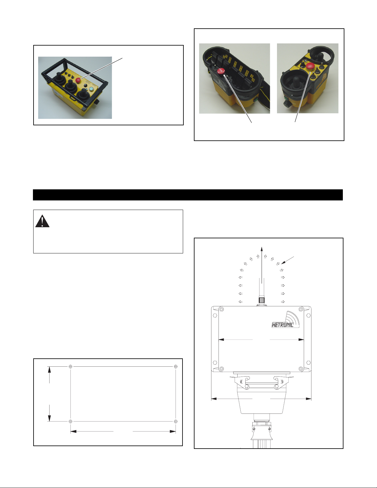
4. Refer to machine’s operator manual for further
instructions.
GL-2
Emergency
Stop
Pushbutton
Nova-L
GL2_0020
INSTALLATION
WARNING: FAILURE TO FOLLOW
INSTRUCTIONS could result in personal
injury and/or damage to equipment. Read and
understand the safety instructions in all
manuals provided.
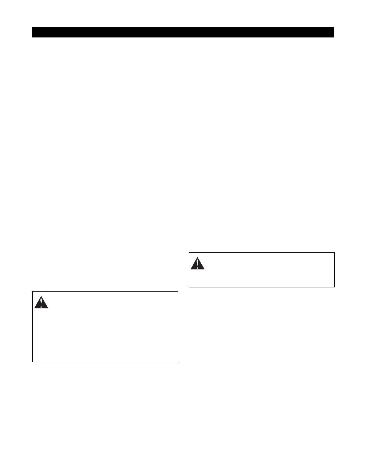
MOUNT THE RECEIVER
Install Receiver and Output Wiring
Select a position for the receiver that provides
protection from violent impact from debris or thrown
materials and is easily accessible. The receiver
housing is rated IP65 and can withstand direct water jet
spray and is protected against penetration of dust.
Therefore, weather and elements should not be the
primary concern when installing the receiver.
Four mounting holes are required when installing the
receiver unit. The drill pattern and recommended
hardware are shown in the following illustration.
NVL_0010
Emergency
Stop
NVL_0020
Pushbuttons
MAINTENANCE
Always shut off power to the machine and the radio
remote control before any assembly, maintenance or
repair.
If the receiver includes an attached antenna, mount the
receiver so that the antenna points straight up. The
area around the antenna should be free of
obstructions, especially metal.
Antenna must be
vertical (pointing up).
8.29"
(210.5 mm)
Area must be
free of
obstructions
4.57"
(116 mm)
DRILL PATTERN
Drill 4 holes 9/32" (7mm).
Use 1/4" or 6mm bolts.
9.13"
(232 mm)
BMS_0030
9.72"
(246.8 mm)
BMS_0040
5

Be sure that the diagnostic LED panel is clearly visible.
Area must be free
of obstructions
ME-3 Module Calibration (Optional)
Determine the maximum stroke of the actuator and set
the ME-3 module accordingly. See the ME-3 Module
Instruction Sheet in the Technical Data Sheet section
for detailed instructions.
2.80"
(71.1 mm)
Operation
Signal
Error
Normal
6.38"
(162 mm)
4.47"
(113.5 mm)
Do not block
visibility of
diagnostic
panel.
6.61"
(167.9 mm)
BMS_0040
The receiver wiring is critical for proper system
operation. Make all connections with good quality
contacts or solder joints to ensure proper electrical
contact.
Supply voltage and ground wiring are crucial and must
be connected to reliable connecting circuitry. Do not
use a chassis ground for this equipment. The ground
wire must be connected directly to the vehicle battery
negative post.
The output control signals to the proportional control
valves should be routed separately from any wiring that
could produce transient voltage interference.
Interference or "induced voltage spikes" could cause
erratic performance of the proportional controls.
INSTALL BATTERY CHARGER
The battery charger unit should be installed in the
vehicle and connected to the vehicle battery with a
fuse. The charger must be operational even when the
vehicle ignition is turned off. The battery charger’s
energy consumption impact is minimal. The charging
system is protected against polarity reversal. Install
and operate the charger in a dry, protected location
inside the vehicle. Optional battery chargers may be
powered by an AC wall plug or a DC cigarette lighter
adapter.
BATTERY HANDLING
Each Hetronic radio remote control system is delivered
with two fully charged batteries. One is inserted in the
battery compartment located on the bottom of the
transmitter. The operating time of the 3.6 V charged
battery is approximately 25-30 hours.
INSERT THE BATTERY
Be sure the battery compartment is clean. Dirt or debris
can cause contact problems.
GL
1. Insert the battery with both guide pins in the
corresponding guide bars of the battery
compartment.
2. Press the battery on the marked spot until it
latches into place.
GL-2
Battery
Mount the Actuators (Optional)
Mount and attach the actuators to the hydraulic valves
or to the mechanical linkage with the brackets supplied.
Attach Wiring Harness (Optional)
Plug the wiring harness into the receiver and into the
corresponding actuators.
Connect Electrical Wiring
Connect all remaining wires (power supply, engine
start-stop, etc.) according to the wiring diagram of the
crane and the radio remote control.
GL2_0010
Nova
1. Insert the battery with both guide bars on the
lower side of the battery in the corresponding
guide slots of the battery compartment.
2. Press the battery until it latches into place.
Nova-L
Battery
NVL_0040
6
ADJUSTMENTS
QUICK-SET SYSTEM
The Quick-Set System provides easier installation,
adjustment and service of the radio remote control
system. Quick-Set allows adjustment of all proportional
function speeds (valve travel) from the transmitter. A
red Program Key is provided to control the
programming mode. When adjustments are complete,
remove the Program Key and store it in a secure
location. Function speeds can be readjusted at any
time.
The system includes a base board, or mother board,
which includes all of the common function circuitry
found in most Hetronic receivers. These functions
include power regulation, decoding the received signal,
12 digital output functions, and the Quick-Set function.
The base board also contains diagnostic LEDs that are
visible on the outside of the transmitter housing to help
quickly diagnose problems.
FUNCTION SPEED ADJUSTMENT
This procedure requires that the receiver is connected
to the machine, all necessary wiring is complete and a
fully charged battery is in the transmitter.
IMPORTANT: The crane must be located in an open
area so that sudden or unexpected crane movements
will not damage buildings or property. All power lines
must be out of reach of the boom. Set the outriggers in
the "out and down" position as recommended by the
crane manufacturer and be sure the crane is stable.
For specific instructions, refer to the crane
manufacturer’s operator manual. Allow the truck
engine to run at "Idle".
5. Insert the red programming key into the
keyswitch.
6. Turn the transmitter "ON".
7. Wait approximately 3 seconds until the second
buzzing sound has finished.
8. Twist the key one quarter turn further to the
program position. (This is only possible with the
red programming key.) Press the "Start/horn"
button for at least one second.
9. To set minimum speed - Deflect the requested
joystick slowly until you hear the vehicle’s horn. If
the horn is connected to the receiver, it will sound
for a brief moment when the joystick reaches the
minimum movement position. Keep the joystick in
this position.
10. Adjust the speed of this function by using the
program "T-O-T" toggle switch (momentary - zero
- momentary). Push the toggle switch toward "+"
to increase speed, toward "-" to decrease speed.
Adjust the function speed to move as slowly as
possible. This helps to achieve a smooth start
when this function is activated.
11. To set maximum speed - Deflect the joystick to its
maximum position. Push the program toggle
switch toward "+" to increase speed, toward "-" to
decrease speed.
WARNING: AVOID INJURY - The crane is
moving during the adjustment of the
functions. Be sure the work area is clear of
obstacles and bystanders.
CAUTION: AVOID INJURY AND PROPERTY
DAMAGE - The crane may respond differently
with radio remote controls than with manual
controls. During the adjustment procedure,
use extreme caution with joystick/lever
movements. Avoid sudden movements and
observe crane motions carefully. The operator
must be standing on dry, level, stable ground
that is free of oil and debris.
1. Use the crane’s manual controls to raise the
boom from its rest. Extend the boom to a safe
starting point.
2. The transmitter must be attached to the operator
with the belt adjusted to a firm fit.
3. Turn the receiver power "ON".
4. Remove the black key from the transmitter
keyswitch.
The receiver can program only one function at a time.
Make sure that only one axis is deflected at a time.
When function adjustment is complete in one direction,
repeat the procedure above for the other directions and
functions. Remember to set values for both high and
low ranges.
After all adjustments are complete, wait at least 10
seconds before turning the transmitter off. The new
values will be automatically stored into the system’s
memory.
If problems occur during the adjustment procedure,
you can revert to the default values of the system.
Remove the receiver lid and press the reset button on
the board. Reinstall the receiver lid.
7

Reset
Button
BMS_0010
OPERATION
WARNING: FAILURE TO FOLLOW
INSTRUCTIONS could result in personal
injury and/or damage to equipment. Read and
understand the safety instructions in all
manuals provided.
HOLDING THE TRANSMITTER
Hold the transmitter with the control panel facing you.
Be sure that you are able to easily read any text and
understand operation symbols. If your transmitter
contains a Tilt Sensor Switch, be sure it is not activated
or the transmitter will not start.
If a belt or strap is provided with your transmitter, use it
at all times. The belt or strap is designed to reduce
stress and increase safety.
WARNING: FAILURE TO FOLLOW
INSTRUCTIONS could result in personal
injury and/or damage to equipment. Always
hold the transmitter in the proper orientation.
Holding the transmitter improperly while
operating the crane/machine could result in
unexpected crane/machine response.
The safety checks described in the following
paragraphs must be completed before the radio remote
control system is activated. These checks must be
performed at least once a day, before the start of any
operation and at all shift changes.
IMPORTANT: A transmitter drawing is included with
each system. Transmitter layout and inscriptions may
vary according to customer requests.
WARNING: FAILURE TO FOLLOW
INSTRUCTIONS could result in personal
injury and/or damage to equipment. Test the
"E-STOP" function as described in the
crane/machine manufacturer’s operator
manual before beginning any operation.
ADDRESS SETTINGS
The address settings are pre-set at the factory in the
ADMO module. However, if the transmitter coder
board, the BMS-1 Base Board, or if the entire
transmitter or receiver are replaced, the ADMO
address must match the system.
IMPORTANT: If the ADMO settings of the transmitter
and receiver do not match, the system will not function.
VISUAL CHECK
Always check the transmitter for any physical damage
before any operation.
• Always keep safety features, guards and controls
in good repair, in place and securely fastened.
• Check equipment for wear or damage.
• Check rubber cuffs and pushbutton caps for wear
or damage.
IMPORTANT: Never operate a transmitter with worn or
damaged parts. Replace immediately with only
Hetronic parts. Contact Hetronic or your Dealer.
START-UP PROCEDURE
This procedure must be carefully followed before
beginning any operation.
1. Be sure that all safety measures required by the
equipment manufacturer have been followed. (i.e.
crane level, stabilizers down, etc.)
2. Be sure the transmitter battery is fully charged.
3. Push in the transmitter E-stop pushbutton.
4. Be sure that all controls, joysticks or paddle
levers are in the Off (neutral) position.
NOTE: If any control, joystick or paddle lever is NOT in
the Off (neutral) position when the Start/Horn button is
pushed, the transmitter will not turn on.
5. Switch the transmitter "ON". A short buzzer signal
will sound.
6. Wait for the second buzzer signal (approx. 3
seconds).
7. The green LED on the transmitter control panel
will flash.This indicates that the transmitter is
working and is ready to use.
8. Disengage the E-stop pushbutton.
9. Push the green pushbutton "Start/horn" on the
transmitter.
10. Check that the machine functions correspond
with the transmitter functions.
IMPORTANT: The machine functions will operate
during this check. Be certain that there are no
obstacles near the machine.
8

11. Push the "EMERGENCY STOP" pushbutton on
the transmitter. Be sure that no functions can be
activated with the "EMERGENCY STOP"
pushbutton depressed.
IMPORTANT: If any function of the radio remote
control activates with the "EMERGENCY STOP"
engaged, the radio remote control must not be used
until it is repaired.
12. Pull out the "EMERGENCY STOP" pushbutton.
13. Push the green pushbutton "Start/horn" on the
transmitter.
14. Both the radio remote control and the machine
are now ready for operation.
IMPORTANT: To avoid accidental start-up, always
engage the E-stop pushbutton and switch the
transmitter "OFF" when not in use. When the
transmitter is not attached to the operator, the key
switch should be removed and stored in a secure
place.
WARNING: TO AVOID SERIOUS INJURY
OR DEATH. Switch the machine "OFF" if
there is a fault or any problems with the safety
check. Contact Hetronic or your dealer
immediately to repair the system. NEVER
operate the machine when the
"EMERGENCY STOP" function does not
operate properly.
Improper operation, maintenance or
adjustment may cause serious injury or
damage to equipment and may void the
warranty.
SPEED CONTROL
This radio remote control system is equipped with a
dual range speed control. The switch allows selection
between high range (rabbit) and low range (snail). The
low range provides <70% of full speed.
NVL_0010
GL-2
GL2_0020
Nova-L
Start
Pushbutton
Start
Pushbuttons
NVL_0020
EMERGENCY STOP
For all emergency situations, push the E-Stop
pushbutton in. To restart the system, disengage the
E-Stop pushbutton and press the Start/Horn
pushbutton. Be sure any dangerous conditions are
corrected and follow the Start Up Procedure above.
SAFE MODE
When the transmitter battery voltage drops below
approximately 3.4 volts, the system automatically goes
into Safe Mode. A buzzer will sound to indicate a low
battery. At the end of the 30 seconds, the transmitter
sends the E-Stop signal and all crane/machine motion
commands are stopped.
To restart the system, a fully charged battery must be
inserted into the transmitter. Proceed with startup
instructions. Always place the discharged battery
directly into the charger.
PROPORTIONAL FUNCTIONS
The proportional functions and speed ranges are
pre-set by Hetronic according to the valve types. Your
dealer can refer to the basic adjustments at any time.
Only the crane manufacturer, dealer or authorized
service representative is allowed to adjust individual
functions, direction and speed range.
CAUTION: DO NOT OPEN THE RECEIVER.
All relay and proportional outputs are
accessible on the connection plug.
Unauthorized entry into the receiver could
result in damage to equipment and may void
the warranty.
9

JOYSTICKS OR PADDLE LEVERS
Joysticks and paddle levers are equipped with a spring
return to the center (OFF) position. If the
crane/machine motion is multi-speed, the farther the
lever is pushed, the faster the crane/machine motion
will move. Return the lever to the center position to
stop the crane/machine motion.
OPTION CONTROLS
Each transmitter can be equipped with a variety of
rotary switches, toggle switches or pushbuttons. Each
function is labeled. For specific operational
instructions, refer to the technical documentation
supplied with your transmitter, or contact Hetronic.
TRANSMITTER SHUTDOWN
To shut down the transmitter, turn the key switch to
OFF. Remove the key and place it in a secure location
to prevent unauthorized or unintentional use.
OPTICAL DISPLAYS AND ACOUSTIC
SIGNALS
The radio remote control system uses optical displays
and acoustic signals to show current working status.
Off: Indicates E-Stop condition.
On: Normal operating condition.
• The yellow "Operation" LED
Off: Indicates no power to the base board.
Flashing: Indicates power to the base board.
• The red "Error" LED
Off: Normal operating condition.
Flashing: Failure in the system circuitry. The
transmitter will initialize a self-test routine which
may re-initialize the system. If not, the failure
must be diagnosed.
CAUTION: After pressing the start
pushbutton for approximately 1 second, the
red "Error" LED should stop flashing or go off.
If the LED stays lit, there is a malfunction in
the system. Contact your Dealer or Hetronic
for repairs. Unauthorized entry into the
receiver could result in damage to equipment
and may void the warranty.
Transmitter
1. Turn keyswitch to "ON".
2. One long acoustic signal (buzzer) sounds.
3. After the self-test routine, another buzzer sounds
to indicate that the system is ready to operate.
4. Then press the Start/Horn button to begin system
operation.
NOTE: If the Start/Horn button is pressed before the
second buzzer, the system will not start up.
During transmitter operation, a buzzer signal indicates
when the battery is nearly discharged. The transmitter
will operate for another 30 seconds before going into
E-Stop. Use this time to place the crane/machine in a
safe position.
Receiver
There are four LEDs on the right side of the receiver.
They indicate proper system operation and
malfunctions.
• The green "Signal" LED
Off: No data reception (no communication with
transmitter.
Flashing in a continuous rhythm: The transmitter
is turned "ON" and valid data are received.
Flashing at increased rate: E-Stop signal is being
received.
Flashing, out of rhythm: Indicates RF
interference, transmitter out of range or bad
receiver reception.
• The yellow "Normal" LED
BMS_0020
FREQUENCIES AND ADDRESSES
Each Hetronic radio remote control system contains a
registration-free radio frequency unit, CS 434 or CS
458. Each system consists of a transmitter RF unit and
a receiver RF unit.
CAUTION: AVOID INJURY OR DAMAGE Operating the transmitter without its antenna
could destroy the final stage of the RF
module. DO NOT attempt to change the
Hetronic pre-set frequency or the 16-bit
address. Personal injury and property
damage could result from transmission
interference and may void the warranty.
TRANSMITTER OPTIONS
Each Hetronic radio remote control system is built to
customer specifications. You may have features that
are not described in this manual. Some possible
options are described below. If you have questions,
please contact your dealer or Hetronic.
Back-up Transmitter
Spare transmitters are frequently used in the event that
the primary transmitter is damaged or misplaced. Only
one transmitter is allowed to be active at any given
time.
10

NOTE: If the primary and back-up transmitter are
turned on at the same time, the receiver enters the
Safe Mode.
ADMO Address Plugs
If several radio remote control systems are used,
address plugs can configure a spare transmitter to be
used on any of the cranes/machines. Each address
plug corresponds to a specific crane/machine. When a
specific crane/machine address plug is inserted into
the plug receptacle of the spare transmitter, the
transmitter is automatically configured to operate that
crane/machine.
Optical Low Battery Indicator
This feature is a LED indicator of the low battery
condition. It can be used as an alternative to or in
addition to the buzzer signal.
Advanced Low Battery Indication
This feature is basically a timer that indicates a low
battery condition 10 minutes before the Safe Mode is
entered. This feature is beneficial where placing the
crane or machine in a safe position takes more time
after the low battery is indicated.
Feedback
This feature allows the transmitter to receive and
display information such as crane/machine status,
warnings, etc. The feedback can be displayed as visual
graphics or buzzers.
RF Booster
This feature boosts the RF transmission power for
extended range operation of up to 1 mile. It is to be
used only in applications that are safe to operate
outside of the operator’s visual range.
Priority Transmitters
This feature is the capability to have several
independent cranes/machines controlled by one
transmitter. Priority levels can be set to allow the main
transmitter to override the control of individual
crane/machine transmitters.
RF Units
AUTX - Auto Synthesizer - The function of a transmitter
to automatically search a range to find a frequency
without interference.
SCRX - Scan Synthesizer - The function of a receiver
to respond only to a designated transmitter and finding
the frequency that the transmitter is transmitting on.
CRANE/MACHINE CONTROL WITH
MULTIPLE TRANSMITTERS
Multiple crane/machine applications may require the
use of more than one transmitter. Or a single
transmitter may be required to control several
cranes/machines simultaneously. The common
methods of control for these situations are "Pitch and
Catch" and "Independent/Combined Control."
Pitch and Catch
Multiple (usually two) transmitters control one receiver,
but not at the same time. All transmitters must be
configured with the same address code as the receiver,
but set at a different frequency channel.
The first transmitter turned on controls the
crane/machine. The operator moves the load to a
hand-off location and turns the transmitter off. The
second operator turns his transmitter on and takes
control of the crane/machine. The receiver only
accepts commands from one transmitter at a time.
Independent/Combined Multiple
Crane/Machine Control
This configuration is for applications that require
multiple (usually two) cranes/machines on a single
runway. Each crane/machine can be controlled
independently. The cranes/machines may also be
operated in tandem by one operator.
The transmitters built for these applications contain
Selector switches. These switches select each
crane/machine individually or any combination of
designated cranes/machines.
With transmitter interlocks, each transmitter contains a
different address code and frequency channel. The
receivers have a RF module and decoder set for each
transmitter. A special module inside the receiver
determines which transmitter is requesting control of
each crane/machine. The module locks the transmitter
signal to the receiver and all other transmitter signals
are ignored.
When that transmitter is turned OFF, the
cranes/machines are available to be controlled by a
different transmitter.
Universal Transmitter
One transmitter is engineered to communicate with
several different systems. The transmitter can be
quickly modified to control any crane or machine in a
designated facility or fleet.
11

OPTIONAL SAFETY FEATURES
"Press to Operate" (PTO) Safety Switch
To release a crane/machine load, it may be necessary
to incorporate a two-handed activation with a "Press to
Operate" (PTO) safety switch. The PTO switch must be
activated at the same time the load release switch is
activated. This feature ensures that the load is not
released by incidental activation of the release switch.
Typical applications for a PTO switch are magnetic and
vacuum lifting devices or grabs of any type.
A PTO safety switch can also be incorporated into a
joystick as a button on top of a joystick lever.
"Lift to Operate" (LTO) Joystick
"Lift to Operate" (LTO) joysticks have a mechanical
device located near the top of the joystick handle. It
must be held and lifted upward to activate the joystick.
LTO ensures that the joystick is not accidentally
activated. This feature is available on GR transmitters.
"Lift to Operate" (LTO) Toggle Switch
LTO toggle switches must be lifted from their static
positions in order for the switch to be activated. LTO
toggle switches can be "maintained" or "momentary".
This feature is mechanically activated and is available
on Nova, GL, and GR transmitters.
Magnet Switch
The magnet switch is used mainly in transmitter
docking station situations. Its function is to enable
certain functions only when the transmitter is secured
in a predetermined location.
Corrosion Protection
To resist damage in corrosive environments, all metal
components are fabricated of stainless steel. This can
include receiver housings, hardware, screws, etc.
Solid State DC Outputs
This feature enables Hetronic to eliminate costly
intermediate relay panels for DC crane/machine
operations. There are no moving parts in the
contactors, thereby lowering maintenance costs.
Tilt Sensor Switch
The tilt sensor switch activates if the transmitter is tilted
more than 30 or 45 degrees from level. The switch has
a delay time of 0-5 seconds.The delay time is set at the
factory to customer specifications. If this switch senses
an unacceptable tilt for as long as the time delay is set,
the transmitter either sends the E-stop signal to the
receiver or enables/disables certain functions
according to customer specifications. This safety
device is useful if the operator is in danger of losing his
footing or control of the transmitter. It is available on GL
and GR transmitters.
Range Limitation
This feature uses a RF signal to restrict operator
movement to a predetermined range limit. It can be
preset at the factory, or adjusted in the field.
Interlocking Functions
This feature prevents contradictory operator
commands from the transmitter. Certain functions can
be enabled or disabled when another function is
activated or inactive. An example is hoist up and hoist
down. Activating both functions would most likely
damage the equipment. Therefore, hoist up is
interlocked with hoist down so that when one is
activated the other can not be. The systems are
capable of interlocking any functions.
12

MAINTENANCE
BATTERY CHARGING SYSTEM
The Hetronic UCH-2 is a new and improved battery
charging system. It includes upgraded features to
better charge and troubleshoot the battery.
Battery and charger contacts are gold-plated and
self-cleaning to ensure positive connection. The battery
and charger contacts are mechanically cleaned each
time the battery is removed from or inserted into the
battery compartment.
CHARGE LED
FAST
CHARGE LED
READY LED
Features
• Normal charge or Fast charge of Hetronic
standard batteries
• Trickle charge - After charging process is
complete, battery can remain in charger without
being damaged by over-charge.
• Battery diagnostics - Charger determines if
battery is damaged.
• Gold plated contacts ensure clean, positive
contact between battery and charger.
• LED status lights indicate charging process as
well as battery diagnostics
The Battery Charger
One battery charger is designed for 115/230 VAC and
plugs into a typical wall outlet. Another charger is
designed for 12/24 VDC and is wired into the constant
crane/machine power source.
When the battery is inserted into the charger, a flashing
“CHARGE” LED lights. The charge process is
terminated by detecting peak battery voltage or after 5
hours and the “READY” light goes on. When the
“READY” light is lit, the charger continues to "trickle"
charge the battery.
NOTE: If the battery is bad and has an open cell, no
LEDs will light up. If the battery has a shorted cell, the
“CHARGE” LED will blink continuously. In either case,
the battery must not be used. Properly dispose of the
bad battery.
FAST
CHARGE
Button
Battery
Battery Charger Technical Specifications
Charging current Normal: 200 mAh
Fast charge: 680 mAh
Charge time
(Standard Hetronic
1200 mAh battery)
Temperature range -20C to +75C
Power supply DC - 12-24 VDC, polarity
NOTE: Will also charge 9.6 V batteries. Internal
modification (jumper 2) and mechanical limiters must be
removed.
Normal: approx. 6 hours
Fast charge: less than 2 hours
(no damage to battery, or
negative effect to duty cycles)
protected
AC - 110-220 VAC, US/Japan or
EU plug
LED Description
Yellow LED
Red LED
Green LED
Yellow CHARGE
LED
Lights constantly - Charging
Continuous flashing -
Damaged battery cell (short)
Red FAST
On - Fast charge in process
CHARGE LED
Green READY
LED
No LED on after
battery inserted
On - Battery fully charged,
trickle mode in process
Damaged battery cell (open
cell)
Charging the Battery
1. Insert the battery with both guide pins in the
corresponding guide bars into the battery
compartment of the battery charger.
2. Press the battery on the marked spot until it
latches into its compartment. The LED labeled
“CHARGE” flashes for two seconds, then stays lit
during the charging process.
13

3. When the battery is fully charged, the “READY”
LED lights up and the “CHARGE” LED goes off.
Charging time could take up to 5 hours,
depending on the condition of the battery.
4. Leave the battery in the charger until it is needed.
The charger supplies a “trickle” charge but will not
over-charge the battery.
CHARGE LED
FAST
CHARGE
Button
FAST
CHARGE LED
Battery
READY LED
DC Only
Battery Technical Specifications
Battery type NiMh (nickel metal hydride)
Capacity (typical) 1200 mAh
Typical operation
time
Memory effect None
Duty cycle Can be recharged at least 500 times
10 - 20 hours with one charge
(depending on TX configuration)
(after 500 charges, over 80% of
capacity remains and will diminish
gradually)
Changing the Battery
The battery voltage is monitored continuously by the
transmitter.
A buzzer in the transmitter sounds when the battery is
nearly discharged. When the transmitter signals, the
battery must be changed immediately.
1. Position the crane/machine into a safe place or
safe condition within 30 seconds after hearing the
signal.
Optional
DC
US/Japan AC
European AC
Cigarette
Lighter
Adapter
Battery Charger Power Options
Fast Charge
1. Insert the battery into the charger as described
above. The LED labeled “CHARGE” flashes for
two seconds, then stays lit.
2. Press the “FAST CHARGE” button. The FAST
CHARGE LED lights also and stays lit during the
charge process.
3. When the battery is fully charged, the “READY”
LED lights up and the “CHARGE” and “FAST
CHARGE” LEDs turn off.
If you have questions or problems operating your
battery charger, please contact your dealer or Hetronic.
Hetronic Battery Information
Standard Hetronic rechargeable batteries are the nickel
metal hydride type. These batteries have no “memory
effect” when charging a battery that is not fully
discharged.
WARNING: The transmitter will switch to the
EMERGENCY STOP condition after 30
seconds.
NOTE: If your transmitter is equipped with Advanced
Low Battery Indication, you have up to 10 minutes to
place the crane/machine in a safe position. The exact
amount of time is determined by customer
specifications. Refer to the technical drawings for each
radio remote control system.
2. Press the E-stop pushbutton.
3. Switch the transmitter "OFF".
4. Push the discharged battery slightly forward and
lift it out of the battery compartment.
5. Insert a fully charged battery.
6. Follow "Start-up Procedure" to begin operation.
BATTERY DISPOSAL
IMPORTANT: AVOID ENVIRONMENTAL
POLLUTION. Electronic equipment and components
are considered to be hazardous waste. Discarded
rechargeable batteries are hazardous waste and must
not be disposed of with typical refuse. Contact a
professional hazardous waste disposal service.
14
WARNING: EXPLOSIVE GASES AND
FLYING DEBRIS can cause death or serious
injury. Use only Hetronic replacement
batteries. Use of unauthorized replacement
batteries could cause a battery explosion,
resulting in injury or death of the operator or
other people in the work area.

TROUBLESHOOTING
If the system does not operate after normal start-up as
described in Operation Section of this manual, follow
the recommended troubleshooting sequence to help
isolate the cause and determine corrective action.
PROBLEM PROBABLE CAUSE CORRECTION
If the system will not respond to the steps below or the
LEDs indicate a failure, contact the Hetronic Service
Department or your authorized dealer.
System will not initialize
after normal start-up
procedure
E-Stop reset Push the Start button again. If the system is
being initialized from an E-Stop condition,
the Start button must be pressed twice - first
to clear the E-Stop, then to start the system.
Joystick or paddle lever not in
center position
E-Stop switch engaged Pull out E-Stop switch. Restart system by
Battery fully discharged Check battery to ensure a full charge.
No power to the receiver Check the diagnostic LEDs on the side of
Ensure that all joysticks and paddle levers
are in center position when the Start button
is activated.
pressing Start twice.
Replace with fully charged battery if
necessary.
the receiver to be sure power is applied.
Ensure that the system is grounded to the
negative battery terminal. The LEDs also
indicate normal transmitter communication,
interference, and E-Stop conditions.
15

SPECIFICATIONS
Model BMS
(Baseboard Module System)
System GA 610
General Data
Frequency 70 cm Band (Selectable
458.800 Mhz to 459.175
Mhz) or CS434
Range approx. 100 m ( 328 ft.)
Address 20-bit - 1,000,000 possible
Operating temperature -30° to +70° C
(-22° F to 158° F)
Data Format 2400/4800 Baud, even
parity, 8 data bits, 2 stop bits,
hamming distance 4
Receiver
Protective System IP 65
System Synthesizer Technology
Voltage Supply 12 to 24 VDC (-50% - +20%)
Current rating,
Transmission
GL - Dimensions - with
protection frame
GL - Weight - including
battery and belt
Nova - Dimensions - with
protection frame
Nova - Weight - including
battery and belt
approx. 83 mA
300 mm x 180 mm x 180 mm
(11.8 in x 7.0 in x 7.0 in)
2.4 Kg (5.28 lbs)
230 mm x 170 mm x 106 mm
(9.0 in x 6.7 in x 4.2 in)
1.8 Kg (3.96 lbs)
Decoding Multiple bit scanning,
self-monitoring
Fuses 7.5 amp. / 80 V car fuse
Output Intrinsically safe emergency
stop with two MOS - FET transistors, 12 digital
outputs, potential free 250 V
/ 8 A, 6 analog outputs, 2
speed ranges
Static current 260 mA, Stand-by
Antenna connection TNC - socket
Dimensions - approx. with
rubber buffer
L x B x H
Weight - 2,5 kg ( 5.5 lbs)
265 mm x 161 mm x 111 mm
(10.4 in x 6.3 in x 4.4 in)
Transmitter
Protective System IP 65
Battery Pack 3.6 V / 1200 mAh (NiMh)
Operating time approx 20 h
Transmitting power < 10 mW
Current rating, Self test approx. 75 mA
16

INSTALLATION AND SAFETY TEST DATA
This for must be completed and signed by the person
responsible for installation of this radio remote control
system.
Crane Data
Manufacturer
Model Number
Serial Number
Year of Production
Radio Remote Control Data
Manufacturer Hetronic
Hetronic assumes no responsibility for the correct
installation of the radio remote control system. The
equipment operator must ensure that the radio remote
control system and the crane/machine operate
correctly together. The operator must also ensure that
all safety devices and features are in place and
operating correctly. The operator is responsible for
understanding and following all safety precautions in
this and other applicable operator manuals.
Model BMS
System Type GA 610
System Number
I/We installed the radio remote control system, performed the safety test and inspected the crane/machine. The
appropriate instructions and rules of this machine type are followed.
Place
Date
Company
Name of Installation Technician
Signature
17

DEFINITIONS
Acoustic signal A buzzer or other sound intended to be heard as an alert.
Analog signal Proportional - stepless or infinite control
Belly box A transmitter that is secured to the front of the operator’s body by a belt,
strap or breastplate/harness.
Coder Converts parallel signals into a serial data message
Decoder Coverts a serial data message into parallel signals
Digital signal On/off control
Latching control The function activates when the control is pushed and released. The function
stays on until the control is pushed and released again.
Mainline contactor The primary power supply contactor to the crane/machine controls.
Maintained control The function activates when the control is placed in the ON position. The
function stops when the control is placed in the OFF position.
Momentary control The function activates when the control is placed in the ON position. The
control must be held in place to stay ON. When the control is released, it
returns to the OFF position and the function is stopped.
Proportional control A multi-speed function control that goes faster as the control is pressed
further.
AWG - METRIC CONVERSIONS
AWG Metric Equivalent mm sq. Metric Cable Size mm sq.
20 0.52 0.75
18 0.82 1.0
16 1.32 1.5
14 2.1 2.5
12 3.3 4
10 5.32 6
8 8.5 10
6 13.5 15
4 21.3 25
2 33.7 35
1/0 (0) 53 70.0 (50.0 if current capacity not
exceeded)
2/0 (00) 67.6 70
3/0 (000) 84.4 95
4/0 (0000) 107 120
18

ABBREVIATIONS
A/D Analog to digital conversion
AK Analog channel (German: Analog Kanal)
AMP Ampere
AWG American Wire Gauge
BPS Bits per second
CPU Central Processing Unit
DK Digital channel (German: Digital Kanal)
EMC Electromagnetic compatibility
EMI Electromagnetic immunity
EPROM Electrical programmable read-only memory
FM Frequency modulation
GND Ground
HF High frequency
KHz Kilohertz
LED Light emitting diode
LTO Lift to operate
mAH Milliampere hours
mA Millampere
msec Millisecond
MHz Megahertz
MOV Metal Oxide Varistor type of surge suppressor
mW Milliwatt
NiCd Nickel Cadmium
NiMH Nickel Metal Hydrite
PLC Programmable logic controller
PLL Phased locked loop
PTO Press to operate
PWM Pulse width modulation
R/C Resistor/Capacitor type of surge suppressor
RF Radio frequency
RMS Root mean squared
Rx Receiver
RxD Receiving data
SMD Surface mount device
SMT Surface mount technology
TTL Transistor transistor logic
Tx Transmitter
TxD Transmitting data
Ub Operating power
Uv Microvolts
VAC Volts alternating current
VDC Volts direct current
19

FREQUENCY CHART CS 458
CS 458 Frequency
Hetronic
& Jumper Settings
The Hetronic Radio Remote Control System address code and frequency channel are set at the
factory. The address code and frequency channel may need to be set if you have purchased a
replacement or spare transmitter.
• Never change the address code or frequency channel of the original transmitter
purchased with your system.
• Never change the address code settings in the receiver.
• Never operate two transmitters at the same time that are set with the same
frequency channel and address code.
Group USA - Jumper "J3" Open Group GB - Jumper "J3" Closed
Channel
A0
A1
A2
A3
A4
A5
A6
A7
A8
A9
A10
A11
A12
A13
A14
A15
Frequency (MHz)
458.800
458.825
458.850
458.875
458.900
458.925
458.950
458.975
459.000
459.025
459.050
459.075
459.100
459.152
459.150
459.175
D0
ON
OFF
ON
OFF
ON
OFF
ON
OFF
ON
OFF
ON
OFF
ON
OFF
ON
OFF
D1
ON
ON
OFF
OFF
ON
ON
OFF
OFF
ON
ON
OFF
OFF
ON
ON
OFF
OFF
D2
ON
ON
ON
ON
OFF
OFF
OFF
OFF
ON
ON
ON
ON
OFF
OFF
OFF
OFF
D3
ON
ON
ON
ON
ON
ON
ON
ON
OFF
OFF
OFF
OFF
OFF
OFF
OFF
OFF
Frequency (MHz)
458.525
458.550
458.575
458.600
458.625
458.650
458.675
458.700
458.725
458.750
458.775
458.825
458.8375
458.900
458.825
458.900
SALS_008.0_CS 458
May 2003
Channel
B0
B1
B2
B3
B4
B5
B6
B7
B8
B9
B10
B11
B12
B13
B14
B15
TX
X1
J3
RX
AD0D1D2D3
20
X7
D0D1D2D3
J3
www.hetronic.com

FREQUENCY CHART CS 447
CS 447 Frequency
Hetronic
& Jumper Settings
The Hetronic Radio Remote Control System address code and frequency channel are set at the
factory. The address code and frequency channel may need to be set if you have purchased a
replacement or spare transmitter.
• Never change the address code or frequency channel of the original transmitter
purchased with your system.
• Never change the address code settings in the receiver.
• Never operate two transmitters at the same time that are set with the same
frequency channel and address code.
Group A - Jumper "J3" Closed Group B - Jumper "J3" Open
Channel
A1
A2
A3
A4
A5
A6
A7
A8
A9
A10
A11
A12
A13
A14
A15
A16
Frequency (MHz)
447.8625
447.8750
447.8875
447.9000
447.9125
447.9250
447.9375
447.9500
447.9625
447.9750
447.9875
447.8750
447.9000
447.9250
447.9500
447.9750
D0
ON
OFF
ON
OFF
ON
OFF
ON
OFF
ON
OFF
ON
OFF
ON
OFF
ON
OFF
D1
ON
ON
OFF
OFF
ON
ON
OFF
OFF
ON
ON
OFF
OFF
ON
ON
OFF
OFF
D2
ON
ON
ON
ON
OFF
OFF
OFF
OFF
ON
ON
ON
ON
OFF
OFF
OFF
OFF
D3
Frequency (MHz)
ON
ON
ON
ON
ON
ON
ON
ON
OFF
OFF
OFF
OFF
OFF
OFF
OFF
OFF
447.275
447.300
447.325
447.350
447.400
447.450
447.500
447.550
447.600
447.650
447.700
447.750
447.775
447.800
447.825
447.850
SALS_011.0_CS 447
May 2003
Channel
B1
B2
B3
B4
B5
B6
B7
B8
B9
B10
B11
B12
B13
B14
B15
B16
TX
X1
J3
RX
AD0D1D2D3
21
X7
D0D1D2D3
J3
www.hetronic.com

FREQUENCY CHART CS 434
CS 434 Frequency
Hetronic
& Jumper Settings
The Hetronic Radio Remote Control System address code and frequency channel are set at the
factory. The address code and frequency channel may need to be set if you have purchased a
replacement or spare transmitter.
• Never change the address code or frequency channel of the original transmitter
purchased with your system.
• Never change the address code settings in the receiver.
• Never operate two transmitters at the same time that are set with the same
frequency channel and address code.
Group A - Jumper "J3" Closed Group B - Jumper "J3" Open
Channel
A1
A2
A3
A4
A5
A6
A7
A8
A9
A10
A11
A12
A13
A14
A15
A16
Frequency (MHz)
433.875
433.925
433.975
434.025
434.075
434.125
434.175
434.225
434.275
434.325
434.375
434.425
434.475
434.525
434.575
434.625
D0
ON
OFF
ON
OFF
ON
OFF
ON
OFF
ON
OFF
ON
OFF
ON
OFF
ON
OFF
D1
ON
ON
OFF
OFF
ON
ON
OFF
OFF
ON
ON
OFF
OFF
ON
ON
OFF
OFF
D2
ON
ON
ON
ON
OFF
OFF
OFF
OFF
ON
ON
ON
ON
OFF
OFF
OFF
OFF
Frequency (MHz)
D3
ON
ON
ON
ON
ON
ON
ON
ON
OFF
OFF
OFF
OFF
OFF
OFF
OFF
OFF
433.900
433.950
434.000
434.050
434.100
434.150
434.200
434.250
434.300
434.350
434.400
434.450
434.500
434.550
434.600
434.650
SALS_009.0_CS 434
May 2003
Channel
B1
B2
B3
B4
B5
B6
B7
B8
B9
B10
B11
B12
B13
B14
B15
B16
TX
X1
J3
RX
AD0D1D2D3
22
X7
D0D1D2D3
J3
www.hetronic.com

WARRANTY
Limited Warranty and
Hetronic USA
Terms of Sale
Price: Subject to Change Without Notice
Terms: Net 30 Days
F.O.B: Hetronic USA, Inc.
Oklahoma City, Oklahoma
Hetronic, Inc., hereafter referred to as Company, guarantees all items manufactured by it against any defects
of material and/or workmanship for a period of one year from the date of shipment. Company makes NO
OTHER WARRANTY, EXPRESSED OR IMPLIED, AS TO THE MERCHANTABILITY OR FITNESS OF THE
ITEMS FOR THEIR INTENDED USE OR AS TO THEIR PERFORMANCE. Any statement, description or
specification in Company's literature is for the sole purpose of identification of items sold by the Company
and imparts no guarantee, warranty or undertaking by Company of any kind. Components and accessories
not manufactured by Hetronic are not included in this warranty and are warranted separately by their
respective manufacturers.
Company's sole liability shall to be to repair at its factory, or replace, any item returned to it within one year
from date of shipment, which Company finds to contain defective material or workmanship. All items to be
repaired or replaced shall be shipped to Company (Note: return authorization by Company is required) within
said one year period, freight prepaid, as a condition to repair or replace defective material or workmanship.
Company's herein assumed responsibility does not cover defects resulting from improper installation,
maintenance, or improper use. Any corrective maintenance performed by anyone other than the Company
during the warranty period shall void the warranty. Company shall not be liable for damages of any kind from
any cause whatsoever beyond the price of the defective Company supplied items involved. Company shall
not be liable for economic loss, property damage, or other consequential damages or physical injury
sustained by the purchaser or by any third party as a result of the use of any Company supplied items or
materials.
List prices or discounts are subject to change without notice. Quoted prices will be honored for a period of 90
days from the date of the written quotation unless otherwise stated.
Orders are not subject to alteration or cancellation except upon written consent of Company and payment of
proper cancellation charges, when deemed applicable by Company.
Materials or items may not be returned for credit, without the prior written consent of the Company. Any
authorized return of materials or items shall be subject to a restocking charge equal to 20% of the net
invoiced amount after Company determines that the material or item is in good condition and may be resold
without alteration or service.
Terms of payment are NET 30 days. All materials and items are sold F.O.B. Company's shipping point.
Company retains a security interest in all items sold by it so long as they remain in Company's possession to
secure all obligations of purchaser to Company. A processing fee will be applied to all invoices for requested
prepaid freight charges other than UPS. A service charge will be incurred on past due accounts extending
beyond the terms of sale described above, at a rate of 1.5% per month of the net balance extending beyond
30 days.
The buyer should inspect the goods immediately on their arrival and shall within five days of their arrival give
written notice to the Company of the claim that the goods do not conform with the terms of the contract. If the
buyer shall fail to give such notice, the goods shall be deemed to conform with the terms of the contract. Any
claim for material or item shortages must be accompanied by copies of the bill of lading and packing slip.
Delivery schedules or commitments are based upon current production
capacities, material or component availability and inventory and may be
changed as conditions require. Company shall not be liable for loss or
damage of any kind resulting from delay or inability to deliver on account of
fire, labor troubles, accident, acts of civil or military authorities, or from any
other cause beyond Company's control.
WRTY_002 Warranty & Terms
April 2003
23
www.hetronic.com
 Loading...