

Page 1

ERGO-S
USER OPERATION MANUAL
10/2018
www.hetronic.com
USER’S MANUAL
te
Page 2

USER’S MANUAL | ERGO-S
Table of Contents
1. Safety ........................................................................................................................................ 4
1.1 Intended Use ........................................................................................................................ 4
1.2 Symbol Notation ................................................................................................................... 4
1.3 Practices and Laws .............................................................................................................. 4
1.4 Required Operator Training .................................................................................................. 4
1.5 Possible Sources of Danger ................................................................................................. 4
1.6 Protective Features .............................................................................................................. 5
1.7 STOP in case of EMERGENCY ............................................................................................ 5
1.8 Caring for your ERGO-S ....................................................................................................... 5
2. Introduction and Functional Description ..................................................................................... 6
2.1 Production and System Numbers ......................................................................................... 6
2.2 Before Operating Your Wireless Control Unit ........................................................................ 6
2.3 Unit Label Areas and Meanings ............................................................................................ 6
3. Your ERGO-S Transmitter ......................................................................................................... 7
3.1 General Description .............................................................................................................. 7
3.2 ERGO-S Basic Features ....................................................................................................... 7
3.3 Standard ERGO-S 2.4GHz Configuration ............................................................................. 8
4. Operating Your Transmitter ....................................................................................................... 9
4.1 Holding Your Transmitter ............................................................................................... 9
4.2 Visually Checking Your Transmitter ............................................................................... 9
4.3 Powering Up and Starting Your Transmitter ................................................................... 9
4.4 Transmitter Initialization with Standard Status LED Indicator ......................................... 9
4.5 Transmitter Initialization with Graphic User Interface (TFT) and Standard Status LED
Indicator ..................................................................................................................................... 9
4.6 Turning OFF the Transmitter and Stopping the Radio Remote Control ........................ 10
4.7 LED Behaviour and Meanings ............................................................................................ 11
4.8 Battery Level Indication ...................................................................................................... 11
4.9 Multi Address Mode ............................................................................................................ 11
4.10 Magnetic Belt Clip (if equipped) ........................................................................................ 11
5. Configuring Your ERGO-S ....................................................................................................... 12
5.1 Entering Service Mode ....................................................................................................... 12
5.2 Adjusting Settings in Service Mode ..................................................................................... 12
6. Theory of Operation ................................................................................................................. 17
6.1 Stop Function ..................................................................................................................... 17
7. Changing the battery ............................................................................................................... 18
7.1 Recharging your Batteries .................................................................................................. 18
7.2 Battery Disposal ................................................................................................................. 19
7.3 Prolonged Battery Life ........................................................................................................ 19
8. Troubleshooting ....................................................................................................................... 20
9. Specifications .......................................................................................................................... 21
10. Warranty, Service, Repairs and Maintenance ........................................................................ 22
11. Regulatory Information .......................................................................................................... 23
11.1 Europe .............................................................................................................................. 23
11.2 North America................................................................................................................... 23
11.3 Industry Canada (IC/ISED) Statement .............................................................................. 24
Appendix A .................................................................................................................................. 26
Definition of terms .................................................................................................................... 26
Appendix B .................................................................................................................................. 27
B.1 Operator Safety Basics ...................................................................................................... 27
B.2 Safety Checklist ................................................................................................................. 27
Appendix C .................................................................................................................................. 29
C.1 Spare Parts List ................................................................................................................. 29
2
Page 3

USER’S MANUAL | ERGO-S
List of Figures
Figure 1. Blank Rating Plate ................................................................................................... 6
Figure 2. ERGO-S Transmitter (Right, Front, Left) .................................................................. 8
Figure 3. Stop Screen .......................................................................................................... 10
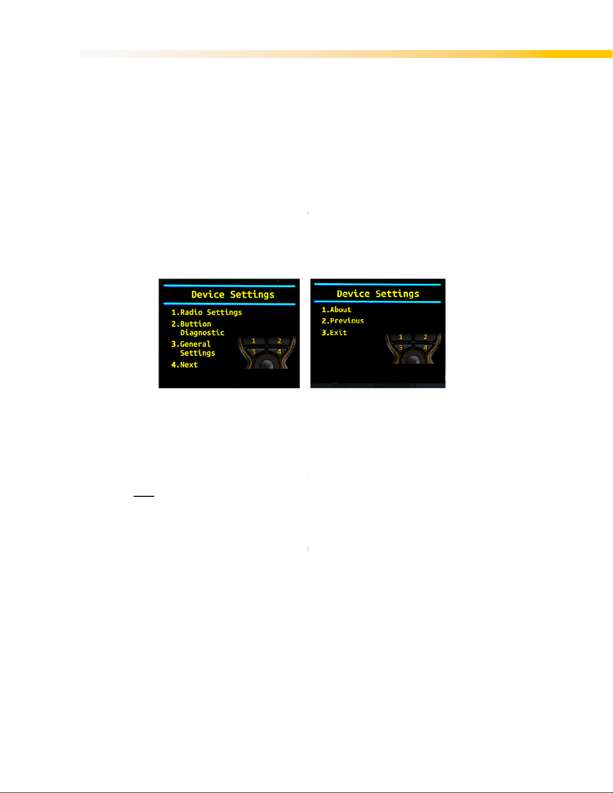
Figure 4. Pages 1 and 2 of the Device Settings menu .......................................................... 12
Figure 5. Radio Settings menu ............................................................................................. 13
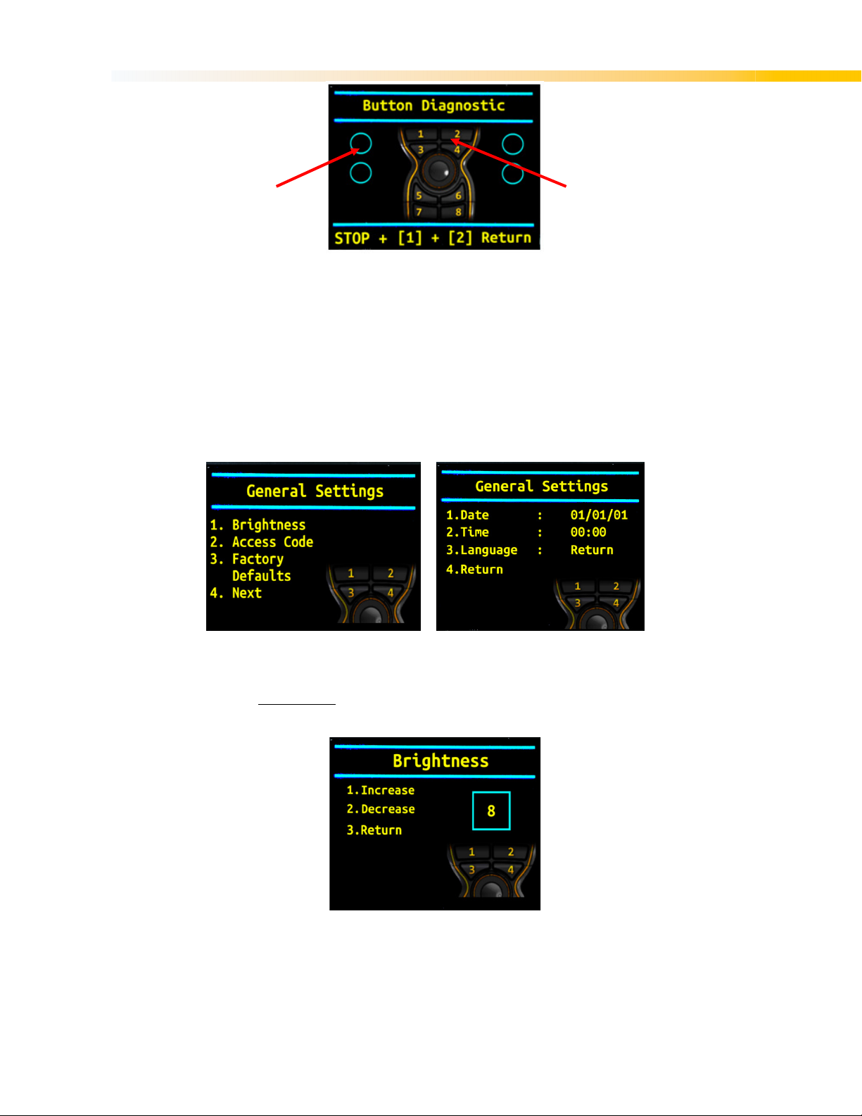
Figure 6. Button Diagnostic page on Transmitter .................................................................. 14
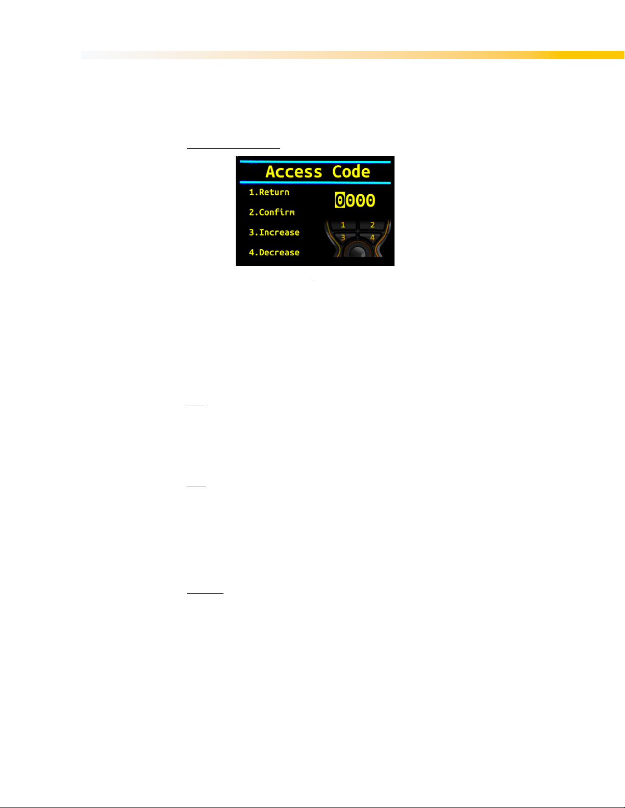
Figure 7. Options found under General Settings menu ......................................................... 14
Figure 8. Adjusting TFT Brightness ...................................................................................... 14
Figure 9. Making Changes to the Access Code .................................................................... 15
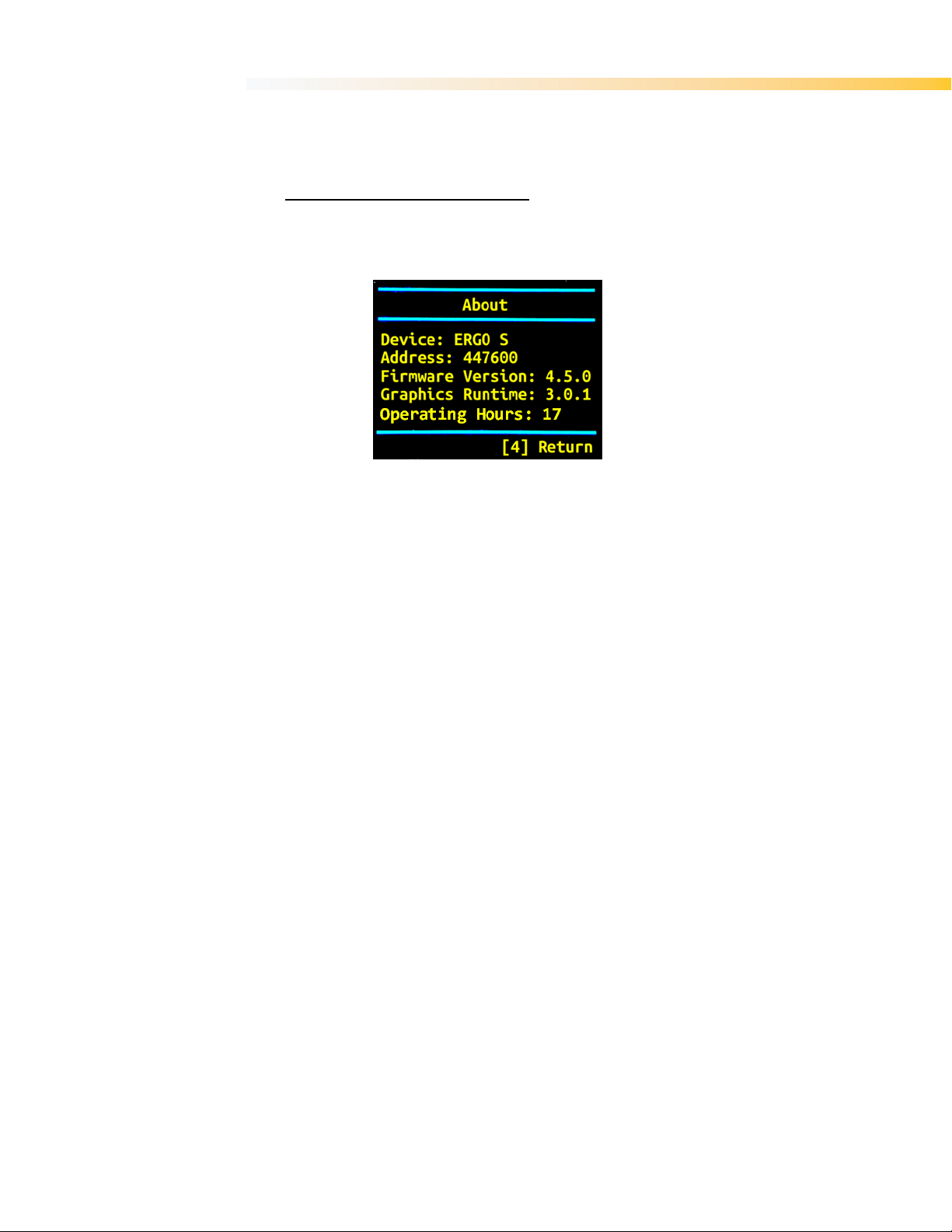
Figure 10. Information provided in the 'About' screen ............................................................. 16
Figure 11. Inserting Battery .................................................................................................... 18
Figure 12. Charging ERGO-S Battery ..................................................................................... 18
Figure 13. Bench-top or wall-mount variations ........................................................................ 19
List of Tables
Table 1. ERGO-S Transmitter features .................................................................................... 8
Table 2. LED Behaviour and Meanings .................................................................................. 11
Table 3. Troubleshooting tips ................................................................................................. 20
Table 4. Technical Specification ............................................................................................. 21
Table 5. Battery Technical Specification................................................................................. 21
Table 6. List of Spare Parts .................................................................................................... 29
3
Page 4
USER’S MANUAL | ERGO-S
1. S
afety
1.1 Intended Use
Your radio remote control is designed for remote operation of machines and systems using safe
wireless communications technology. Any modification, reconstruction or extension of the systems
without a written agreement of Hetronic may lead to the loss of your warranty and guarantee
claims.
Hetronic assumes no liability for damages resulting out of the non-observance of this operating
manual. All persons, working with this radio remote control must
Be suitably trained and qualified as required by the safety regulations.
Strictly comply with the contents of this operating manual.
Before starting the radio remote control you must have read and fully understood this operating
manual. The Safety Checklist in Appendix B is intended to be followed before each time the
transmitter is powered up for operation.
1.2 Symbol Notation
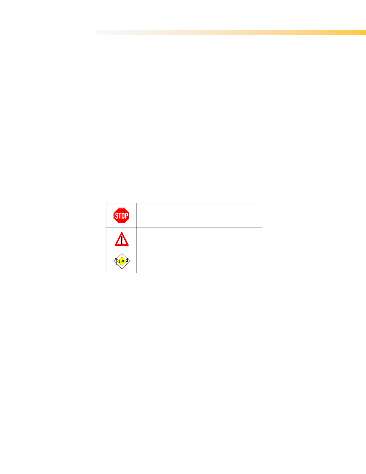
The following symbols are used in this operating manual. The safety alert symbol is used in decals
on the unit and with proper operation procedures in this manual.
Understand the safety message. It contains important information about personal safety on or near
the unit.
STOP! This symbol gives you warning of imminent danger of life, risk of
accident and risk of injury, as well as damage to property i n case of nonobservance of the working instructions.
ATTENTION! This symbol advises against a possible damage to the
system in case of non-observance of the working instructions.
TIP! This symbol points to features and information which allow for an
easier handling or operation.
1.3 Practices and Laws
Practice safe working precautions for the benefit of yourself and others.
Be alert to unsafe conditions and the possibility of minor, moderate, or serious injury or death.
Learn applicable rules and laws in your area.
1.4 Required Operator Training
The original purchaser of this unit was instructed by the seller on safe and proper operation. If unit
is to be used by someone other than original purchaser; loaned, rented or sold, ALWAYS provide
this manual and any needed safety training before operation. ALWAYS read and understand the
documentation for any machine to be controlled by radio remote control.
1.5 Possible Sources of Danger
This device is part of a system that makes remote control via wireless radio signals possible. The
transmission of control commands can take place around obstacles and out of the operator’s direct
line of sight. Take the following precautions to prevent accidental start-up and possible injury or
damage:
4
Page 5
USER’S MANUAL | ERGO-S
Switch “OFF” the transmitter when it is not in use. Unless the transmitter has user
access control password configured, remove the battery if unit is placed away from the
operator.
Disconnect the power supply from the receiver before any assembly, maintenance or
repair work is done.
AVOID SYSTEM DAMAGE - ALWAYS disconnect receiver power supply and control
wiring before welding on any part of the machine.
Never remove or alter any of the safety features.
ALWAYS confirm that the machine and radio remote control Stop functions work
properly BEFORE beginning any machine operation.
1.6 Protective Features
This transmitter is equipped with electronic and mechanical safety features. Control signals from
other transmitters cannot be processed because transmission coding is unique to each system.
1.7 STOP in case of EMERGENCY
Push the emergency stop on the machine.
1.8 Caring for your ERGO-S
The enclosure materials employed on the ERGO-S transmitter have been carefully selected to
minimise maintenance requirements.
Buy a Hetronic ERGO-S holster and screen protector. These will take care of your
transmitter by preventing it from being subject to knocks and scratches. This helps to
keep the unit’s appearance longer and may also protect it from some internal damage
should you accidentally knock or drop it.
Always use genuine chargers and accessories. Cheaper ones that are not
compatible or made for going with your ERGO-S can harm the unit or lessen its
lifespan.
Do not keep your ERGO-S stored in a closed container for extended periods of time unless it is
powered off and the battery is removed from the unit. Charging the ERGO-S in a closed container
is a potential fire hazard and may shorten its lifespan. Lithium-Ion batteries give off heat when
charging and when discharging. Keep your battery percentage between 40%-80% for longer
battery life.
Clean your ERGO-S regularly. Use damp cloth or alcohol wipes to clean the unit’s
exterior surfaces. Do not use aggressive cleaning agents that may inadvertently
damage the unit.
5
Page 6

USER’S MANUAL | ERGO-S
2. I
We congratulate you on the purchase of your new Hetronic ERGO-S push button transmitter. You
have chosen a high quality product. Familiarise yourself with the unit before using it for the first
time. In addition please carefully refer to the operating instructions and the safety advise given in
this manual. Only use the product as instructed and only for the intended field of application. Keep
these instructions in a safe place. If you pass the product on to anyone else, please ensure that
you also pass on all the documentation with it.
ntroduction and Functional Description
2.1 Production and System Numbers
Before contacting your dealer or Hetronic about service, repair or replacement parts, note the
equipment Production and System numbers. These numbers are located on the silver label affixed
to the unit.
2.2 Before Operating Your Wireless Control Unit
Confirm that installation of all your system components has been properly completed. Before start
up, ALWAYS confirm that the machine and radio remote control Stop functions work properly.
Understand all Safety Precautions provided in the manuals and review control functions and
operation of the machine and this radio remote control system. When not in use, turn the
transmitter off and store in a safe place to prevent unauthorized use. Ensure that the USB Dongle
(which acts as a security key to program the transmitter) is kept in a separate but safe and secure
place. If the machine does not respond properly, immediately stop operation. Turn off the
transmitter and report the condition to your supervisor.
Turn off the transmitter before any maintenance work is done. Always have fresh batteries on hand
or an optional rechargeable battery pack in the battery charger to ensure the availability of a fully
charged battery. Installation, setup and service must be performed by authorized and qualified
personnel only.
2.3 Unit Label Areas and Meanings
1. Specific approvals, such as CE, FCC, IC, etc.
2. Type of ERGO-S transmitter
3. Eleven-digit Production Number
4. Eleven-digit System Number
5. Frequency information
6. Current rating
7. Supply voltage
Figure 1. Blank Rating Plate
6
Page 7

USER’S MANUAL | ERGO-S
3. Y
our ERGO-S Transmitter
3.1 General Description
The ERGO-S is an ergonomically designed, programmable wireless transmitter capable of
transmitting up to 32 on/off functions to remotely control a machine.
Your transmitter is encased in a rugged IP65 rated housing, is battery-powered, and comes
equipped with built-in low battery detection. Standard equipment includes two 3.4Ah Lithium-Ion
batteries and battery charger.
3.2 ERGO-S Basic Features
• Fully programmable via H-Link
• 8 push buttons with up to two detents
• 4 push buttons with single detent, one of which is the power button
• 1 proportional Joystick or Selector Switch
• Minimum 100 m (300 ft.) range using CS4XX and CS8xx modules
• Minimum 60 m (196 ft.) range using CS2400 RF module
• Typically 100 m (300 ft.) range using on board MFS radio
• Internal Antenna
• Auto power off feature (configurable)
• Infrared (configurable)
• USB Interface
• Tilt Sensor
• Low Battery detection
• Status bi-colour LED Red/Green
• Feedback LEDs bi-colour Red/Green
• Cable Control
• Multi-Address Mode
• Magnetic Belt Clip
• Data Logging (configurable)
• Rechargeable battery pack
7
Page 8
USER’S MANUAL | ERGO-S
9-11
12
13
14
15
16
17
18
19
20
21
22
3.3 Standard ERGO-S 2.4GHz Configuration
Your ERGO-S 2.4GHz transmitter is factory programmed to one of the following switch
configurations:
A. ERGO-S 2.4GHz-V1
11 Single detent pushbutton
1 Single detent POWER pushbutton
1 Joystick or Selector Switch
B. ERGO-S 2.4 GHz-V2
3 Single detent pushbuttons
8 Double detent pushbuttons
1 Single detent POWER pushbutton
1 Joystick or Selector Switch
An optional 2.4” 240x320 TFT screen provides real-time visual information during operation of the
ERGO-S transmitter. It is used to change configuration settings, provide two-way feedback and
display transmitter diagnostic information such as battery life, signal strength and button status.
The status and feedback LEDs have the same positioning when the TFT is also present on the
transmitter.
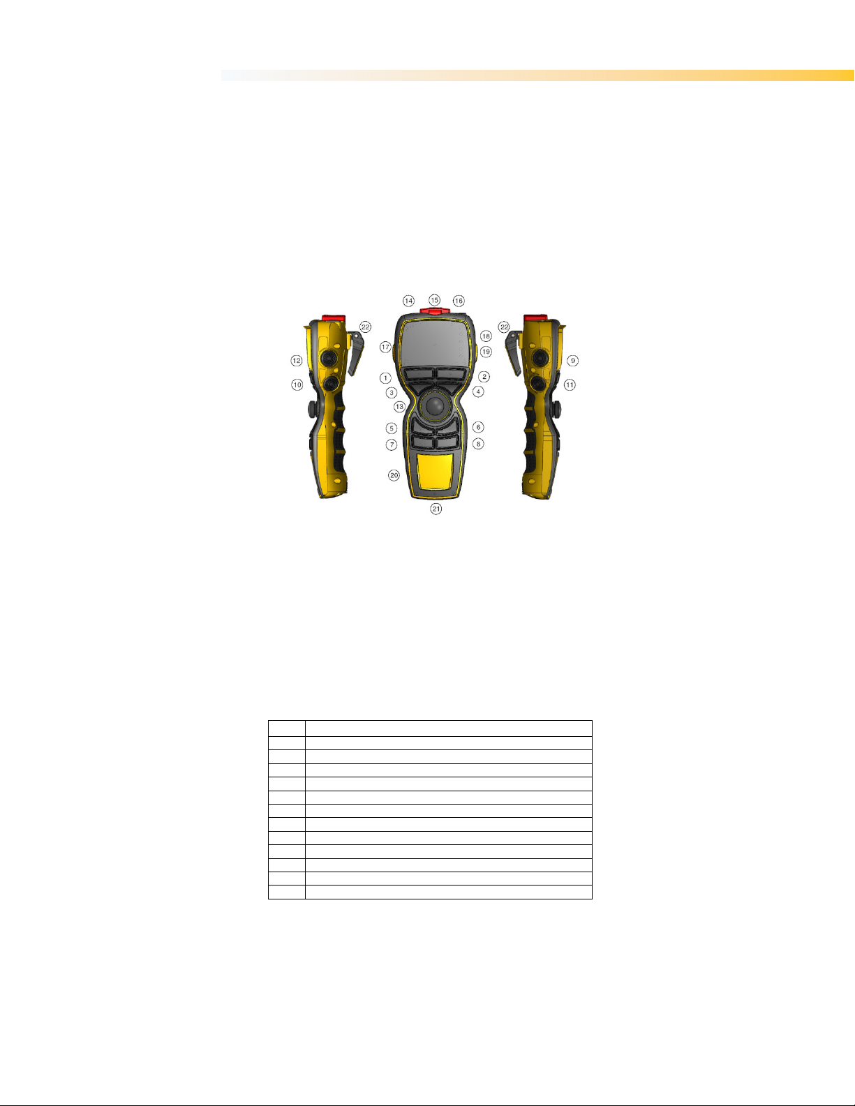
Figure 2. ERGO-S Transmitter (Right, Front, Left)
1-8
Up to 2 Detent Momentary Pushbutton (S2-S9)
Single Detent Momentary Pushbutton (S10-S12)
Single Detent Power/Start Pushbutton (S1)
Joystick or Selector Switch (S13)
Infra Red
STOP Pushbutton (S0)
USB Port Type A
TFT Display
Status LED
LED Feedback bi-colour Red/Green (L1-L3)
Customised Logo Area
Battery Compartment (located in the bottom)
Magnetic Belt Clip
Table 1. ERGO-S Transmitter features
8
Page 9

USER’S MANUAL | ERGO-S
4. O
perating Your Transmitter
4.1 Holding Your Transmitter
Hold the transmitter upright with the front facing you. Confirm that you are able to easily read and
understand any operation text or symbols. Complete the following procedures once a day, before
the start of an operation and at all shift changes.
4.2 Visually Checking Your Transmitter
Always check the transmitter for any physical damage before any operation. Check equipment for
wear or damage and confirm that you can read and understand all of the safety labels. Never
operate a transmitter with worn out or damaged parts.
4.3 Powering Up and Starting Your Transmitter
NOTE: When the transmitter is not being used by the operator, it must be stored in a safe place.
1. Confirm that all safety measures required by the equipment manufacturer have been followed.
2. Insert a battery adapter with fresh batteries into the battery compartment of the transmitter.
3. Insert the USB key supplied with the transmitter in the ERGO-S port (16).
4. Turn ON the receiver.
5. Press START (S1). The transmitter will perform a routine initialization upon start up.
4.4 Transmitter Initialization with Standard Status LED Indicator
Upon turning the transmitter ON, all the front LEDs light up as solid colours and then switch off
before the unit performs the routine initialization.
During initialization, if the coder finds an error in the radio module, address, configuration or
feedback, the transmitter will boot up and the failure will be displayed as a blinking RED status
LED at the baud rate. The transmitter may then be connected to Hetronic PC-Link (refer to
Programming and Servicing Manual for instructions) for the Error to be corrected.
After a successful initialization, the ERGO-S transmitter will enter Normal Operation Mode. The
Green LED will blink at the baud rate i.e. the LED toggles on with every transmitted telegram
frame. All other LEDs switch off. Test all machine functions. Refer to your machine, transmitter and
receiver documentation as needed.
4.5 Transmitter Initialization with Graphic User Interface (TFT) and
Standard Status LED Indicator
Upon turning the transmitter ON, the TFT screen turns ON and all the front LEDs light up as solid
colours and then switch off before the unit performs the routine initialization.
During initialization, if the coder finds an error in the radio module, address, configuration or
feedback, the transmitter will boot up and the failure will be displayed as a blinking RED status
LED at the baud rate. The error will also be displayed on the screen. The transmitter may then be
connected to Hetronic PC-Link (instructions can be found in Programming and Service Manual) for
the Error to be corrected.
After a successful initialization, the ERGO-S transmitter will enter Normal Operation Mode and
display the Splash screen. The correct Operation Access Code must be inputted for the ERGO-S
to start operating.
NOTE: This can be changed/enabled/disabled when the transmitter is in Service mode during
operation or through Hetronic PC-Link. Refer to Section 5.1 for instructions on how to change
when in Service Mode and in Programming and Service Manual for Hetronic PC-Link instructions.
9
Page 10
USER’S MANUAL | ERGO-S
The basic home screen will then be displayed and the Green LED will also blink at the baud rate
i.e. the LED toggles on with every transmitted telegram frame. All other LEDs switch off. Test all
machine functions. Refer to your machine, transmitter and receiver documentation as needed.
4.6 Turning OFF the Transmitter and Stopping the Radio Remote Control
Below are the steps to follow to turn off the transmitter:
1. Press the STOP button (S0).
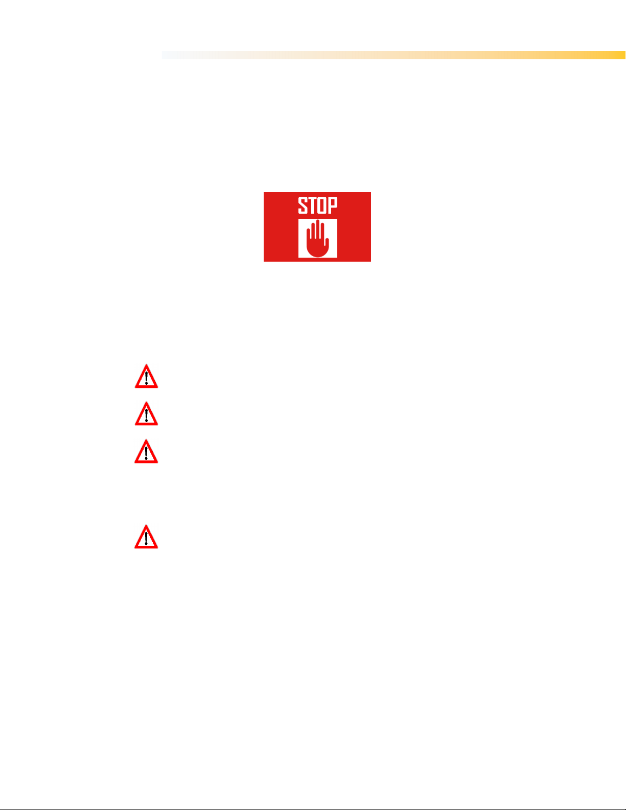
The STOP screen appears, the RED status LED blinks at a fast rate and the transmitter sends a
Stop telegram to the receiver. Upon receiving the Stop telegram, the receiver goes into Safe Mode
and turns OFF all receiver outputs.
Figure 3. Stop Screen
2. Press the Start button (S1) and the Shut Down Delay timer starts. The transmitter shuts off once
the delay timer is over. This is normally set to 2 seconds by default but can be programmed
differently (refer to Programming and Service Manual). The OFF state of the LED indicates that the
transmitter has switched off. If the Start/Power button is not pressed the Transmitter does not
switch OFF.
Note: If the user wishes to resume operation, this is possible by deactivating the STOP switch.
WARNING: Holding the transmitter improperly while operating your machine could result
in unexpected machine response.
WARNING: Test the stop function as described in the machine manufacturer’s operator
manual before beginning any operation.
WARNING: To avoid accidental start-up, always press STOP when not in use.
Turn OFF your machine if there is a fault or problem with the safety check.
NEVER operate the machine if the STOP function does not work properly.
WARNING: Improper operation, maintenance or adjustment may cause serious injury or
damage to equipment and may void the warranty.
10
Page 11

USER’S MANUAL | ERGO-S
4.7 LED Behaviour and Meanings
Result Meaning
Red & Green LEDs turn ON always. Service Mode.
Green LED Blinks.
Red LED Blinks at fast rate.
Red & Green LED Blinks. H-link data transmitted to PC application.
Red & Green LED Blinks at fast rate. Boot loader mode to update the firmware.
Red LED Blinks. FB / RF / Address / Configuration Error on Startup.
Table 2. LED Behaviour and Meanings
Data is being transmitted.
Stop switch active. Stop Data is being transmitted.
4.8 Battery Level Indication
Unless the transmitter is equipped with a TFT screen, in which case the Battery Level is also
displayed on the status bar, the transmitter uses two different warning signs to show the user that
the battery needs replacement.
When the Low Battery level warning has been triggered, the RED status LED will blink at a slow
rate. The GREEN status LED will still blink at the same rate as the baud rate.
In addition to low battery warning, a fixed critical battery level is also monitored. When critical
battery level is reached, the RED Status LED will blink faster. The coder will automatically trigger
the Stop telegram for about 5 seconds until it shuts off.
4.9 Multi Address Mode
This function provides the possibility to have the transmitter control a number of receivers, one at a
time, depending on the address selected. The user can select the required receiver using the
selector switch (S13).
4.10 Magnetic Belt Clip (if equipped)
The practical magnetic belt clip allows the user to hang the ERGO-S transmitter to any steel
surface and continue operation hands free or store the transmitter hung vertically when not in use
and have easy access to it.
11
Page 12
12
Your ERGO
, certain
module and Channel Selection, Screen Brightness, Date and Time, TX Baud Rate, and others
is only accessible on transmitters equipped with the optional graphic user
interface. The units equipped with the standard status LEDs can only have their settings updated
Refer to Programming and Service Manual for instructions.
1. Make sure STOP switch (S0) on transmitter is released.
S by pressing the Start button (
12) pressed until the Splash screen disappears and the ‘
3. Input the ‘Service Access’ code and perform the appropriate selections.
Access Code which the transmitter is configured with is “
Pages 1 and 2 of the
5.2 Adjusting Settings in Service Mod
The four topmost buttons on the front panel are used to n
change setting parameters within the menus. The menu selection changes with every screen and
the description of what each of the four buttons will do is exp
Once the user exits ‘Service Mode’ the changes are
Key, only if it already contains a settings file
configuration settings is inserted in the transmit
whether the settings on the USB Key are to be saved to the coder (“Copy to Coder”) or
whether the settings on the coder are to replace the existing ones (“Copy to USB Key”).
anging
The user has the possibility of checking or changing the Radio Settings directly from the
ce Mode.
USER’S MANUAL | ERGO-S
5. C
When the Transmitter is in Service Mode
may be checked and edited.
NOTE: Service Mode
via Hetronic PC-Link tool.
onfiguring
5.1 Entering Service Mode
2. Switch on ERGO-
-S
configuration settings such as: Access code, RF
,
S1) and then keeping the side switches (9 and
Device Settings’ screen appears.
The default Service
1234”.
Figure 4.
Note:
The user has the possibility of checking or ch
the transmitter from the below menus.
5.2.1. Radio Settings Menu
transmitter from the respective menu in Servi
Device Settings menu
e
avigate through Service Mode and also to
lained next to the button number.
automatically saved to the USB
. Whenever a USB Key with different
ter, the user is prompted to choose
the following features or settings directly from
Page 13

13
Radio Settings menu
Press button 1 to enter Radio Settings menu
through the list of
ection and return to main ‘
of the control telegram
8xx MHz radio modules. The standard baud rate of
Hetronic standard 2.4GHz
Rate when the transmitter is in Service Mode one has to:
Settings menu
2. Keep pressing button 3 to scroll through the available baud r
3. Press button 4 to save selection and return to main ‘
The baud rate for the transmitter must be identical to that of the receiver.
the baud rate of a unit is changed, the bau
supports all other baud rates in cases when non
The button diagnostic checks can be carried out
Press button 2 for Button Diagnostic page
step) or side (1
Step button, the respective diagnostic identifier for that button
switches on blue. When the second step is pressed, the identifier will change to green. 1
switches will only use the blue identifier. If a button is n
Figure 5.
Frequency Channel or Group
1.
2. Keep pressing button 2 to scroll
one is visible.
3. Press button 4 to save sel
Transmitter Baud Rate
The allowable baud rates
9600bits/second for the Hetronic standard 4xx115200bits/second is used for
1. Press button 1 to enter Radio
desired one is visible.
accordingly.
Note: The coder still
used.
USER’S MANUAL | ERGO-S
.
channels or groups until the desired
Device Settings’ page.
that may be configured are 4800 or
radio modules. To change the TX Baud
.
ates and stop when the
Device Settings’ page.
Whenever
d rate of the paired unit must be changed
-standard radio modules are
5.2.2. Button Diagnostic Checks
Step and 2-Step switches are working properly.
1.
2. Press any front (1-step or 2-
When pressing the first step of a 2-
remains on.
directly from the transmitter to ensure that all 1-
from main ‘Device Settings’ menu.
-Step) buttons to test proper functionality.
-Step
ot functioning well, the diagnostic identifier
Page 14
14
Button Diagnostic page on Transmitter
Once all checks are made, the user can return to the main screen by making
whilst holding buttons 1 and 2 pres
following settings may be accessed and adjusted from their respective menus as outlined
under
setting 1
Adjusting TFT Brightness
Side switch
diagnostic
identifier
Figure 6.
button is pressed
5.2.3. General Settings
The
below:
USER’S MANUAL | ERGO-S
Front panel
switch
diagnostic
identifier
sure the STOP
sed simultaneously.
Figure 7. Options found
TFT Brightness
TFT brightness can be adjusted between
Figure 8.
General Settings menu
and setting 8, with 8 being the brightest.
Page 15
15
1. Press button 3 to enter General Settings
3. Press button 1 to increase brightness or button 2 to decrease
ess button 3 to save the new setting and return to the General Settings menu.
aking Changes to the Access Code
Settings menu
2. Press button 2 to go to Access Code page.
increment (or button 4 to decrement) the highlighted digit and button 2 to
4. When all the required changes have been made, press button 2 to confirm the new
tings menu
2. Press button 4 to go to next page of General Settings menu
Time displayed on the status bar of your ERGO
Settings menu
2. Press button 4 to go to next page of General Settings menu.
The language of the menus in Service Mode can be changed to
to enter General Settings menu.
2. Press button 4 to go to next page of General Settings menu.
3. Press button 3 to scroll through the list of available languages.
2, Press button 1 to go to Brightness page.
4. Pr
Operational Access Code
Figure 9. M
USER’S MANUAL | ERGO-S
menu.
brightness.
1. Press button 3 to enter General
3. Press button 3 to
confirm and move on to the next digit.
access code.
Date
1. Press button 3 to enter General Set
3. Press button 1 to change Date.
Time
update the time from the transmitter:
1. Press button 3 to enter General
3. Press button 2 to change Time.
Language
or German.
1. Press button 3
.
.
.
-S transmitter can only be in 24hrs format. To
.
English, Spanish, French, Italian
Page 16
USER’S MANUAL | ERGO-S
4. Press button 4 to confirm the selection and return to previous page.
5.2.4. About the Transmitter
Transmitter, Radio and Software information
Basic transmitter and software information, including address, can be viewed from the ‘About’
option found in the second page of the ‘Device Settings’ menu. The number of hours of operation
is also shown here.
Figure 10. Information provided in the 'About' screen
1. Press button 4 to go to second page of Device Settings menu
2. Press button 1 to go to ‘About’ page.
3. Press button 4 to return to previous page.
16
Page 17

USER’S MANUAL | ERGO-S
6. T
Your ERGO-S transmitter works with a receiving device to transfer machine control commands via
radio frequency to your machine. The transmitter electronically generates a carrier frequency that
allows it to communicate with the receiver without the use of cables or wires. The receiver then
converts the carrier frequency information into discrete machine control outputs that interface with
your machine’s controls. Each transmitter and receiver that comprises a system is programmed
with a unique address code. This code ensures that machine operations are safe, and that other
remote control equipment cannot unintentionally control your machine. The receiver only accepts
commands from the transmitter with the same address code. The receiver and transmitter have the
address code set at the factory.
heory of Operation
6.1 Stop Function
The most important feature of the radio remote control system is the STOP function. When the
transmitter is turned on, it performs a self-test to confirm that communications are within
designated parameters. If an error is detected, the transmitter will not transmit any signals. The
transmitter sends the STOP pushbutton status along with the specified machine functions. This
method confirms that ongoing operations are safe. If the STOP pushbutton is pressed, the data
telegram changes so that only the stop command is transmitted. No other motion command data is
sent.
This special data telegram places the receiver in Safe Mode, and the stop relays in the receiver
open. All other machine functions are completely disabled in the receiver.
The STOP button on the transmitter is only a remote stop and will operate only when the
transmitter is powered up.
Pressing the STOP pushbutton does not ensure the machine will come to a complete
stop. STOP button functionality is subject to the wiring of receiver STOP relays to
machine emergency stop circuit and controlled machine logic where applicable.
ALWAYS test the STOP function at the beginning of every operation session or when there is
change of operator.
17
Page 18
USER’S MANUAL | ERGO-S
7. C
You may power your transmitter with a Hetronic rechargeable battery inserted into the bottom of
the transmitter. Follow the instructions below to ensure best performance of your ERGO-S
transmitter and prolonged battery lifetime.
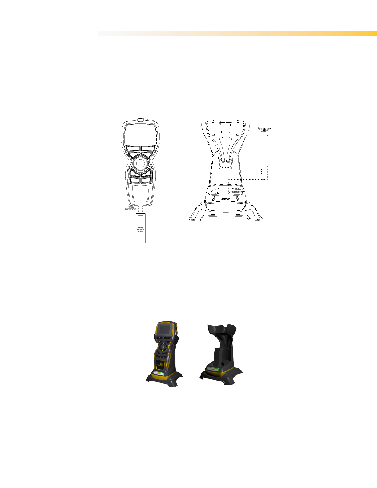
1. Confirm that your batteries are fully-charged. See “Recharging Your Batteries” section below.
2. Slide the recharged battery into the battery compartment at the bottom of the transmitter as
shown, and snap it into place.
hanging the battery
Figure 11. Inserting Battery
7.1 Recharging your Batteries
The two methods which can be used to charge the batteries using the ERGO-S charging unit are:
The user can choose to remove the battery from the transmitter and place it directly in the
charging unit.
Else, the user can opt to charge the battery by placing the whole transmitter unit in the
charger docking station.
Figure 12. Charging ERGO-S Battery
18
Page 19
USER’S MANUAL | ERGO-S
When the transmitter (or the battery) is placed in the docking station, the LED labelled “CHARGE”
flashes for two seconds, and then stays lit during the charging process. When the battery is fully
charged, the “READY” LED lights up and the “CHARGE” LED go off.
NOTE: Charging time could take up to 3.5 hours, depending on the condition of the battery.
Leave the battery in the charger until it is needed. The charger supplies a “trickle” charge but it will
not over-charge the battery.
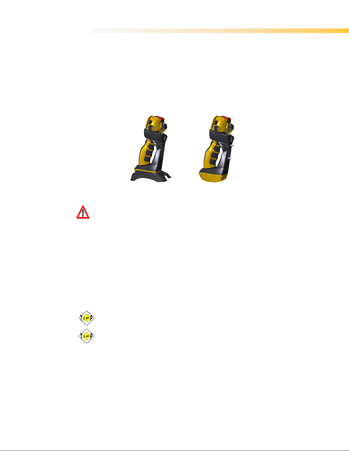
The charger docking station base can be dismantled from the bench-top state to obtain a wallmount charger instead.
Figure 13. Bench-top or wall-mount variations
EXPLOSIVE GASES AND FLYING DEBRIS can cause death or serious injury. Use only
Hetronic replacement rechargeable batteries. Use of unauthorized replacement batteries
could cause a battery explosion resulting in injury or death of the operator or other people
in the work area.
7.2 Battery Disposal
AVOID ENVIRONMENTAL POLLUTION. Recycle your rechargeable batteries according to local
recycling rules and regulations. If you have questions or problems operating your battery charger,
please contact your nearest Hetronic dealer or service center.
Standard Hetronic rechargeable batteries are the Lithium –Ion type. These batteries have no
“memory effect” when charging a battery that is not fully discharged.
7.3 Prolonged Battery Life
Avoid battery misuse, over charging, overheating or regular dropping. This can cause permanent
damage to the cells. Refer to Section 9 (Table 4) for battery specifications.
Never keep a fully charged battery at elevated temperatures. Battery pack does not die
suddenly but the runtime gradually shortens as the capacity fades.
Keeping the charge in the 40% to 80% range will prolong battery life.
Unfortunately there is no avoiding fact that battery has a finite life, after which they will certainly
degrade. Following these basic tips can help delay the inevitable.
19
Page 20
USER’S MANUAL | ERGO-S
cy
Follow instructions under “Setting Frequency
has
8. T
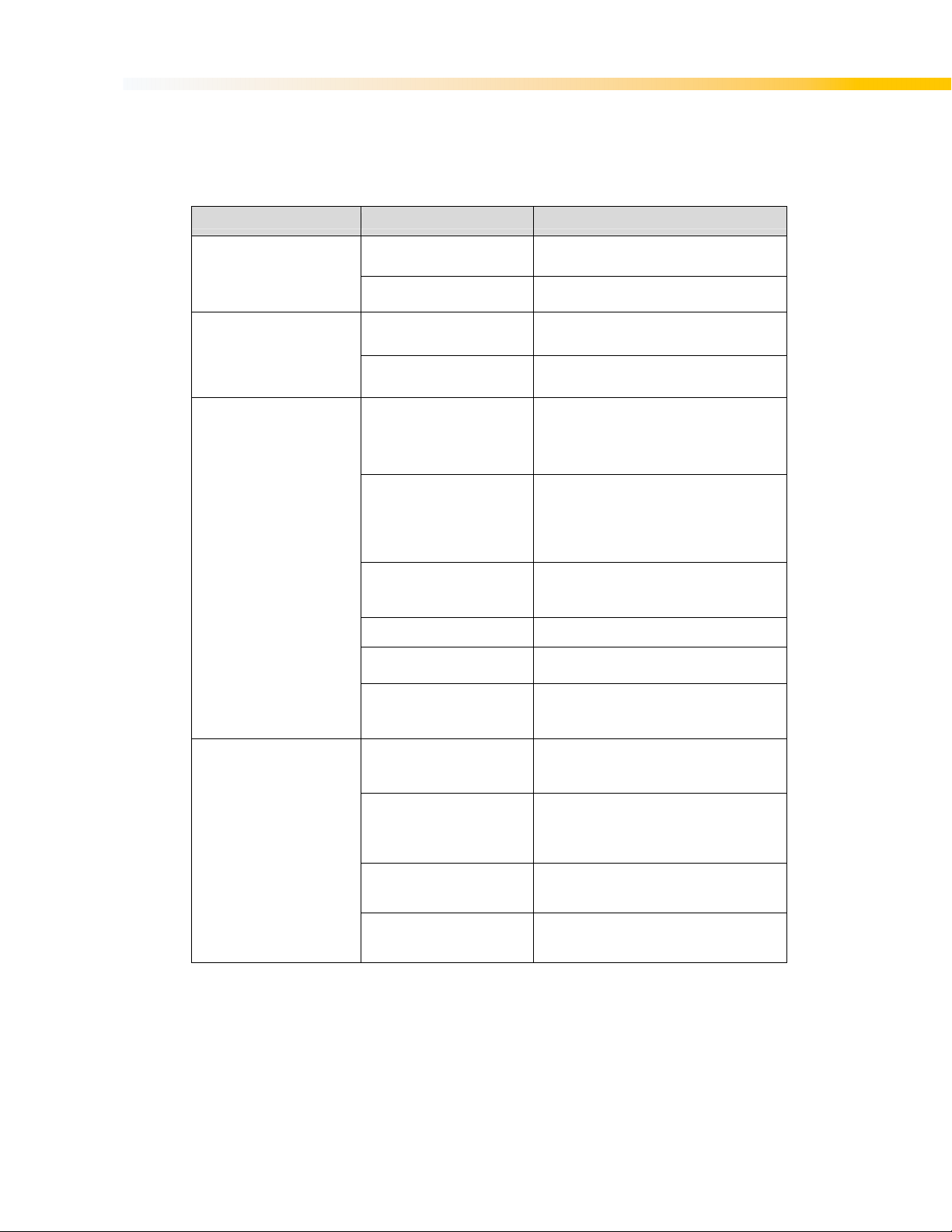
If your ERGO-S does not operate after normal start-up, follow the recommended troubleshooting
sequence to help isolate the cause and determine corrective action. If you need more information,
contact your nearest Hetronic dealer.
roubleshooting
PROBLEM PROBABLE CAUSE CORRECTION
Transmitter won’t start
The transmitter is turned
Incorrect Access code(if
enabled)
Battery fully discharged Replace with fully charged battery if needed
Battery is discharged Replace battery with a fully charged battery
Enter correct access code
on, but does not transmit
(Power LED not flashing)
Component failure
No power to the receiver
Transmitter/receiver frequen
channels do not match
Contact your supervisor or nearest Hetronic
Service Centre
Check the diagnostic LEDs in the receiver to
be sure power is applied. Ensure that the
system is properly grounded
and channels” or contact your supervisor
Transmitter is transmitting
(Power LED flashing), but
machine will not respond
Transmitter out of range
Take the transmitter back into the range of
the receiver, press START
All machine motions
operate intermittently
Receiver power off Turn on power to receiver
Blown fuse in receiver Check all fuses and replace if needed
STOP failure in receiver. Red
STOP LED on PC board is
illuminated
Receiver antenna connection
is loose or missing
External antenna (if used)
loose connection, poor
grounding or interference
Connector inside receiver is
loose
Another frequency may be
interfering with the system
Table 3. Troubleshooting tips
20
Contact your supervisor
Tighten or replace antenna
Tighten antenna and ground connection.
Contact Hetronic or your Dealer for more
information
Check all connectors, reseat if needed
Contact your supervisor
Page 21

USER’S MANUAL | ERGO-S
8 two detent push buttons, 3 single detent push buttons, start
9. S
Operating Temperature Range -20°C . . . 70°C (-4°F . . . 158°F)
Storage Temperature Range -40°C . . . 85°C (-40°F . . . 185°F)
*assuming brand new, fully charged battery and Transmitter set to work in MFS mode
** for full Channel Lists refer to Frequency Bands Radio Modules Charts
pecifications
Transmitter
Housing Ergonomically designed Impact Resistant Polymer Composite
Environmental Protection IP 65 (Exceeds Nema 12/13)
Weight
Dimensions
Antenna Internal
Power Supply 3.7V 3.4Ah Li-Ion rechargeable long life battery
Diagnostics
Operation Time Up to 11 hrs continuous transmission*
Control Configuration
Frequency Range
Power (RF Output) Typically ≤ 10 mW E.I.R.P; depends on country legislation
Typical Operating Range Typically 100 m. (320 ft.) for ≤ 1GHz, 50-60m (170 ft) for ≥ 1Ghz
Safety
Humidity Range 0 - 97% maximum non-condensing
Response Time Less than 100 msec.
Standard Features
Central control options
TFT Pixel: 320*240
Table 4. Technical Specification
Status LED for operation and standard/advanced low battery
V2 –
4xxMHz or 8xxMhz or 9xxMHz or 2.4GHz (subject to purchased
20-bit programmable address concept with up to 1,000,000
USB Memory key that stores configuration settings
~450g (1.21lbs) including battery
And full duplex configuration
Height: 240 mm (9.4 in.)
Width: 110 mm (4.2 in.)
Depth: 80 mm (3.1 in.)
detection
V1 – 11 single detent push buttons, start + stop
+ stop
configuration) **
combinations
Hamming Distance 4
Fully programmable via PC H-Link
Prop Joystick 2-axis
Selector switch 3 position
Blank
Rated Capacity 3400mAh, 0.2C discharging
Storage Environment Conditions
Charging Temperature Range 0°C . . . 45°C (32°F . . . 113°F), max 90%RH
Discharging Temperature Range -20°C . . . 70°C (-4°F . . . 158°F) , max 90%RH
Charging Time (hrs) 5-6
* for long time storage, the cell’s storage voltage should be 3.6-3.9V and it is recommended to charge the cell every six months.
Battery Pack
-20°C . . . 45°C, 90%RH max (for short periods less than 1month)
-10°C . . . 45°C, 90%RH max (for long periods more than 3 months)
15°C . . . 35°C, 85%RH max (recommended storage)*
Table 5. Battery Technical Specification
21
Page 22

USER’S MANUAL | ERGO-S
10. W
Before any service or maintenance intervention on remote controlled equipment always:
Remove all electrical power from the equipment
Follow lock out procedures
Hetronic products are covered by a guarantee/warranty against material, construction and
manufacturing faults. During the guarantee/warranty period, Hetronic may replace the product or
faulty parts. Work under guarantee/warranty must be carried out by Hetronic, or by an authorized
service centre specified by Hetronic. Any modification, reconstruction or extension of the systems
without a written agreement of Hetronic may lead to the loss of your warranty and guarantee
claims.
The following are not covered by the guarantee/warranty:
Faults resulting from normal wear and tear
Consumables e.g. batteries
Products that have been subject to unauthorized modifications
Faults resulting from incorrect installation and use
Maintenance and Preventive Care
Repairs and maintenance must be carried out by qualified personnel
Only use original Hetronic spare parts
Contact your representative for service or any other assistance
Keep the product in a clean, dry place
Keep battery contacts clean
Wipe off dust using a slightly damp, clean cloth
Keep rubber over-mould clean
Remove dust from inside gaps, docking recesses and battery contacts using a vacuum.
NEVER USE:
Abrasive cleaning solutions or high-pressure water jets.
Sharp, pointed objects or any hard items as these may tear the over-mould or rubber
Compressed air as this may lead to ingress protection issues.
Petroleum based solvents including Diesel and Gasoline to clean the unit as these may
Note: Refer to Appendix C for Spare Parts List.
arranty, Service, Repairs and Maintenance
Special care must be taken when cleaning the battery compartment of the transmitter as
detachment of the pressure balance element may lead to ingress protection problems
parts.
react with the silicone rubber of the joystick gaiter.
22
Page 23

23
egulatory Information
declares that the radio equipment types listed
The latest version of the complete EU Declaration of Conformity is available on the Hetronic
This symbol means that inoperative electrical and electron
mixed with household waste. The European Union has implemented collection and
recycling system for which producers are responsible. For proper treatment,
recovery and recycling, please dispose of the product in a designated collecti
Hetronic confirms that, to the best of its knowledge and continual communication with its
ubstances of Very High Concern (SVHC)
of our suppliers no materials from the ECHA are
For the latest version of the complete Declaration of Conformity
please visit the Hetronic website www.hetronic.com.
l and electronic products covered by RoHS and
RoHS2, Hetronic confirms that to the best of its knowledge at the date of this statement, none of
the products supplied by it contain any of the hazardous substances in excess of permitted levels
the Directive 2002/95/EC. The latest version of the complete Declaration of
Conformity is available on the Hetronic website www.hetronic.com
This device complies with Part 15 of the FCC Rules
This device may not cause harmful interference, and
This device must accept any interference received, including interference that may
approved by the manufacturer could void the user's
To comply with FCC RF exposure compliance requirements, this device and its antenna must not
located with, or operating in conjunction with, any other antenna o
USER’S MANUAL | ERGO-S
11. R
11.1 Europe
CE Marking
Hetronic hereby
with Directive 2014/53/EU.
website www.hetronic.com.
WEEE Directive
point.
REACH Compliance
respective suppliers, chemical S
products. Based on the response statements
included on Hetronic products.
RoHS Compliance
As a designer and manufacturer of electrica
in this manual are in compliance
ic products must not be
on
are not included in our
referred to in
11.2 North America
FCC ID: LW9-ERGOS2G4
FCC Recommendations:
conditions:
1.
2.
cause undesired operation.
Changes or modifications not expressly
authority to operate the equipment.
be co-
. Operation is subject to the following two
r transmitter.
Page 24

USER’S MANUAL | ERGO-S
This equipment has been tested and found to comply with the limits for a Class B digital device,
pursuant to Part 15 of the FCC Rules. These limits are designed to provide reasonable protection
against harmful interference when the equipment is operated in a residential environment.
This equipment generates, uses, and can radiate radio frequency energy and, if not installed and
used in accordance with the instructions, may cause harmful interference to radio communications.
However, there is no guarantee that interference will not occur in a particular installation. If this
equipment does cause harmful interference to radio or television reception, which can be
determined by turning the equipment off and on, the user is encouraged to try to correct the
interference by one or more of the following measures:
• Reorient or relocate the receiving antenna
• Increase the separation between the equipment and receiver
• Connect the equipment into an outlet on a circuit different from that to which the receiver is
connected.
• Consult the dealer or an experienced radio/TV technician for help.
11.3 Industry Canada (IC/ISED) Statement
IC ID: 2119B-ERGOS2G4
IC RF Exposure Statement
This device meets the IC requirements for RF exposure in public or uncontrolled environments.
IC Warning
This product complies with Industry Canada’s licence-exempt RSS standards. Operation is subject
to the following two conditions:
1. This device may not cause interference, and
2. This device must accept any interference, including interference that may cause
undesired operation of the device.
24
Page 25
25
may
ge
no
make
g
n
www.hetronic.com
© 2018 Hetronic
All rights reserved. No part of this publication
a retrieval system, or translated into any langua
permission of Hetronic.
Technical information subject to change without
Hetronic reserves the right to discontinue,
products at any time without public notice or obli
damages, whether regarding property, perso
unauthorized replacement parts or service.
USER’S MANUAL | ERGO-S
be reproduced, transmitted, transcribed, stored in
in any form by any means without the written
tice.
changes to, and add improvements upon its
ation. Hetronic disclaims liability for any claims or
al injury or death arising out of the use of
Page 26

USER’S MANUAL | ERGO-S
Appendix A
Definition of terms
The following terms are used throughout the ERGO-S User Manual and may be unfamiliar to some
operators.
Term Definition
baud rate The transmitting speed measured in bits per second.
hamming distance A measurement of data transmission safety. The amount of failures in the
data stream which has to occur during the transmission in order to create a
wrong signal. A low hamming distance means that the test is not very
sensitive to data transmission errors and could potentially be unsafe. A
high hamming distance means that the system is very sensitive and could
potentially be unreliable due to potential noise interference.
26
Page 27

USER’S MANUAL | ERGO-S
Appendix B
B.1 Operator Safety Basics
Before starting your shift, you should make sure that the equipment has a current inspection
certificate and that the necessary inspections and risk assessment checks have been carried out
and are up to date. Also, the equipment must be operated in accordance with the manufacturer’s
instructions.
Furthermore, it is of utmost importance that you know that YOU are primarily responsible for
YOUR OWN health and safety. Wear appropriate Personal Protective Equipment and make sure
that you have had all the necessary training to operate the equipment. The following basic safety
precautions must be adhered to at all times:
1. Transmitter switches must never be mechanically blocked ON or OFF for any motion.
When not in use the transmitter must be turned off. A safe and secure storage space should
be provided for the transmitter unit and the unit should always be placed there when not in
use. This precaution will prevent unauthorized people from operating the crane. Receivers
must be removed from the equipment when it is unlikely that it will be used for a period of
time, and properly stored.
2. All defective or missing safety equipment, mechanical or electrical defects must be
reported to the supervisor without delay. Operation must not continue until all required
repairs are completed. Any changes to the condition of the remote or equipment must be
recorded and communicated to or made accessible by the following operators on shift.
3. Ensure that there is nobody in the path of the travel of the equipment. If there is, stop and
sound the alarm before proceeding.
4. When leaving the equipment area for any reason, switch off the transmitter, remove the
USB Key and store it in a safe and secure place to prevent unauthorized operation.
5. Do not allow any unauthorized person to operate the transmitter at any point.
6. Do not operate the transmitter at a distance where the equipment and all surrounding
objects are not visible. Make sure that your view is not obstructed.
7. Do not attempt to override any of the safety features built into the Radio Remote Control.
8. Put rechargeable batteries on charge at the end of each shift. Chargers are not intended
for outdoor use. Use only indoors.
B.2 Safety Checklist
The following checklist provides general safety guidelines for radio control operation of equipment
by fully qualified and trained operators. These recommendations do not take precedence over any
of the following requirements relating to cranes, hoists, lifting devices or other equipment which
use or include Hetronic products:
Instructions, manuals, and safety warnings of the manufacturers of the equipment
where Hetronic products are used,
Plant safety rules and procedures of the employers and the owners of the facilities
where the Hetronic products are being used,
Occupational Health and Safety Administration (OSHA) regulations,
Safety standards and practices for the industries in which Hetronic products are
used.
27
Page 28

USER’S MANUAL | ERGO-S
Transmitter Start-up and Safety Checklist
1 Are batteries fully charged?
2 Are all switch labels clear and legible?
3 Is the transmitter free from cracks and damages?
4 Are the battery enclosures free from cracks and damages?
5 Is the STOP function working as it should be?
6 Is the correct USB Key being used?
7 Has each function of the transmitter been tested independently to
ensure the equipment is responding correctly?
8 Is the TFT free from cracks, deep scratches and damages?
9 Is there any debris inside the USB port which will prevent the USB Key
from being inserted /functioning properly?
10 Are the Status LEDs on the transmitter clearly visible?
11 Are the charger and plug in good working condition?
12 Is the cable control cable (where applicable) free from kinks and
damages?
13
28
Page 29
USER’S MANUAL | ERGO-S
Appendix C
C.1 Spare Parts List
Keep the safety instructions for future reference. Always download the User Manual instructions
from our website for the latest version available.
Always contact your nearest Hetronic dealer or service center for service and maintenance work
on the product.
Below is a list of spare parts, together with their part number, which by time may need to be
replaced due to wear and tear:
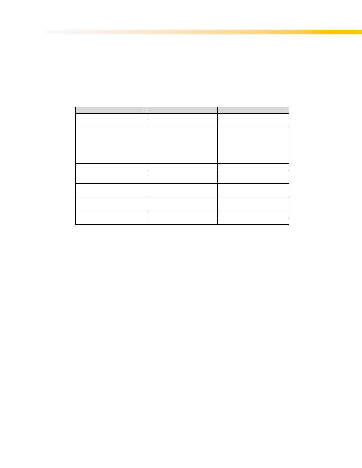
Item Part number Notes
Joystick 67109050
Joystick Gaiter 67240320
The screen gasket
(#11123916) must also be
Display protector 11570011
USB Key cap 11625100
Magnetic Clip
STOP Button kit 1117851502
Grippers in Charging Station 11231245
Base of Charging Station 11231240
Table 6. List of Spare Parts
NOTE: Replacement of parts must be carried out by an authorized service centre specified by
Hetronic.
replaced when changing the
protector. No adhesives must
be used when assembling the
parts in place
These hold the transmitter in
place in the Charging Station
Used in Bench top
configuration
29
 Loading...